WO2024005176A1 - マイクロニードル構造体 - Google Patents
マイクロニードル構造体 Download PDFInfo
- Publication number
- WO2024005176A1 WO2024005176A1 PCT/JP2023/024316 JP2023024316W WO2024005176A1 WO 2024005176 A1 WO2024005176 A1 WO 2024005176A1 JP 2023024316 W JP2023024316 W JP 2023024316W WO 2024005176 A1 WO2024005176 A1 WO 2024005176A1
- Authority
- WO
- WIPO (PCT)
- Prior art keywords
- needle
- water
- resin
- base material
- melting point
- Prior art date
- Legal status (The legal status is an assumption and is not a legal conclusion. Google has not performed a legal analysis and makes no representation as to the accuracy of the status listed.)
- Ceased
Links
Images


Classifications
-
- A—HUMAN NECESSITIES
- A61—MEDICAL OR VETERINARY SCIENCE; HYGIENE
- A61B—DIAGNOSIS; SURGERY; IDENTIFICATION
- A61B5/00—Measuring for diagnostic purposes; Identification of persons
- A61B5/15—Devices for taking samples of blood
- A61B5/150007—Details
- A61B5/150015—Source of blood
- A61B5/150022—Source of blood for capillary blood or interstitial fluid
-
- A—HUMAN NECESSITIES
- A61—MEDICAL OR VETERINARY SCIENCE; HYGIENE
- A61B—DIAGNOSIS; SURGERY; IDENTIFICATION
- A61B5/00—Measuring for diagnostic purposes; Identification of persons
- A61B5/15—Devices for taking samples of blood
- A61B5/150977—Arrays of piercing elements for simultaneous piercing
- A61B5/150984—Microneedles or microblades
-
- A—HUMAN NECESSITIES
- A61—MEDICAL OR VETERINARY SCIENCE; HYGIENE
- A61K—PREPARATIONS FOR MEDICAL, DENTAL OR TOILETRY PURPOSES
- A61K9/00—Medicinal preparations characterised by special physical form
- A61K9/0012—Galenical forms characterised by the site of application
- A61K9/0019—Injectable compositions; Intramuscular, intravenous, arterial, subcutaneous administration; Compositions to be administered through the skin in an invasive manner
- A61K9/0021—Intradermal administration, e.g. through microneedle arrays or needleless injectors
-
- A—HUMAN NECESSITIES
- A61—MEDICAL OR VETERINARY SCIENCE; HYGIENE
- A61L—METHODS OR APPARATUS FOR STERILISING MATERIALS OR OBJECTS IN GENERAL; DISINFECTION, STERILISATION OR DEODORISATION OF AIR; CHEMICAL ASPECTS OF BANDAGES, DRESSINGS, ABSORBENT PADS OR SURGICAL ARTICLES; MATERIALS FOR BANDAGES, DRESSINGS, ABSORBENT PADS OR SURGICAL ARTICLES
- A61L31/00—Materials for other surgical articles, e.g. stents, stent-grafts, shunts, surgical drapes, guide wires, materials for adhesion prevention, occluding devices, surgical gloves, tissue fixation devices
- A61L31/04—Macromolecular materials
- A61L31/042—Polysaccharides
-
- A—HUMAN NECESSITIES
- A61—MEDICAL OR VETERINARY SCIENCE; HYGIENE
- A61M—DEVICES FOR INTRODUCING MEDIA INTO, OR ONTO, THE BODY; DEVICES FOR TRANSDUCING BODY MEDIA OR FOR TAKING MEDIA FROM THE BODY; DEVICES FOR PRODUCING OR ENDING SLEEP OR STUPOR
- A61M37/00—Other apparatus for introducing media into the body; Percutany, i.e. introducing medicines into the body by diffusion through the skin
- A61M37/0015—Other apparatus for introducing media into the body; Percutany, i.e. introducing medicines into the body by diffusion through the skin by using microneedles
-
- G—PHYSICS
- G01—MEASURING; TESTING
- G01N—INVESTIGATING OR ANALYSING MATERIALS BY DETERMINING THEIR CHEMICAL OR PHYSICAL PROPERTIES
- G01N5/00—Analysing materials by weighing, e.g. weighing small particles separated from a gas or liquid
- G01N5/02—Analysing materials by weighing, e.g. weighing small particles separated from a gas or liquid by absorbing or adsorbing components of a material and determining change of weight of the adsorbent, e.g. determining moisture content
-
- A—HUMAN NECESSITIES
- A61—MEDICAL OR VETERINARY SCIENCE; HYGIENE
- A61M—DEVICES FOR INTRODUCING MEDIA INTO, OR ONTO, THE BODY; DEVICES FOR TRANSDUCING BODY MEDIA OR FOR TAKING MEDIA FROM THE BODY; DEVICES FOR PRODUCING OR ENDING SLEEP OR STUPOR
- A61M37/00—Other apparatus for introducing media into the body; Percutany, i.e. introducing medicines into the body by diffusion through the skin
- A61M37/0015—Other apparatus for introducing media into the body; Percutany, i.e. introducing medicines into the body by diffusion through the skin by using microneedles
- A61M2037/0023—Drug applicators using microneedles
-
- A—HUMAN NECESSITIES
- A61—MEDICAL OR VETERINARY SCIENCE; HYGIENE
- A61M—DEVICES FOR INTRODUCING MEDIA INTO, OR ONTO, THE BODY; DEVICES FOR TRANSDUCING BODY MEDIA OR FOR TAKING MEDIA FROM THE BODY; DEVICES FOR PRODUCING OR ENDING SLEEP OR STUPOR
- A61M37/00—Other apparatus for introducing media into the body; Percutany, i.e. introducing medicines into the body by diffusion through the skin
- A61M37/0015—Other apparatus for introducing media into the body; Percutany, i.e. introducing medicines into the body by diffusion through the skin by using microneedles
- A61M2037/003—Other apparatus for introducing media into the body; Percutany, i.e. introducing medicines into the body by diffusion through the skin by using microneedles having a lumen
-
- A—HUMAN NECESSITIES
- A61—MEDICAL OR VETERINARY SCIENCE; HYGIENE
- A61M—DEVICES FOR INTRODUCING MEDIA INTO, OR ONTO, THE BODY; DEVICES FOR TRANSDUCING BODY MEDIA OR FOR TAKING MEDIA FROM THE BODY; DEVICES FOR PRODUCING OR ENDING SLEEP OR STUPOR
- A61M37/00—Other apparatus for introducing media into the body; Percutany, i.e. introducing medicines into the body by diffusion through the skin
- A61M37/0015—Other apparatus for introducing media into the body; Percutany, i.e. introducing medicines into the body by diffusion through the skin by using microneedles
- A61M2037/0046—Solid microneedles
-
- A—HUMAN NECESSITIES
- A61—MEDICAL OR VETERINARY SCIENCE; HYGIENE
- A61M—DEVICES FOR INTRODUCING MEDIA INTO, OR ONTO, THE BODY; DEVICES FOR TRANSDUCING BODY MEDIA OR FOR TAKING MEDIA FROM THE BODY; DEVICES FOR PRODUCING OR ENDING SLEEP OR STUPOR
- A61M37/00—Other apparatus for introducing media into the body; Percutany, i.e. introducing medicines into the body by diffusion through the skin
- A61M37/0015—Other apparatus for introducing media into the body; Percutany, i.e. introducing medicines into the body by diffusion through the skin by using microneedles
- A61M2037/0053—Methods for producing microneedles
-
- A—HUMAN NECESSITIES
- A61—MEDICAL OR VETERINARY SCIENCE; HYGIENE
- A61M—DEVICES FOR INTRODUCING MEDIA INTO, OR ONTO, THE BODY; DEVICES FOR TRANSDUCING BODY MEDIA OR FOR TAKING MEDIA FROM THE BODY; DEVICES FOR PRODUCING OR ENDING SLEEP OR STUPOR
- A61M2205/00—General characteristics of the apparatus
- A61M2205/70—General characteristics of the apparatus with testing or calibration facilities
Definitions
- the present invention relates to a microneedle structure.
- microneedles have been proposed that supply drugs into the body and collect body fluids from the body through through holes formed in the microneedles.
- microneedles are known that include a microneedle-shaped biocompatible matrix and porous particles provided on the surface or at least partially inside the biocompatible matrix (Patent Document 1). .
- Patent Document 1 the biocompatible material that makes up the microneedles is swollen within a few seconds to a few hours when inserted into the skin, and is absorbed into living tissue, so the microneedles do not swell in the body. It is assumed that it will be absorbed. However, from the viewpoint of safety, it is desirable to remove the inserted microneedles so that they remain in the skin as little as possible.
- a microneedle containing porous particles as shown in Patent Document 1 is inserted and then removed from the skin, there is a problem that the microneedle is damaged due to insufficient strength. Furthermore, if the strength of the needle-like portion of the microneedle is low, it may break when puncturing the skin, reducing the efficiency of drug supply, etc.
- the present invention was made in view of the above circumstances, and an object of the present invention is to provide a microneedle structure having a needle-like portion with high strength.
- the present invention first provides a microneedle structure comprising a needle-like part in which a hole is formed, the needle-like part having a weight average molecular weight of 25,000.
- a microneedle structure characterized by containing a low melting point resin having a melting point of 130° C. or lower (invention 1).
- the needle-shaped portion contains a low melting point resin having a weight average molecular weight of 25,000 or more and a melting point of 130° C. or less, so that sufficient strength can be maintained.
- the speed at which fluid is absorbed or released from the needle may be lower than in a structure in which holes are opened only at the top of the needle.
- the needle-shaped portion may become brittle and have insufficient strength.
- the present invention contains a low melting point resin with a weight average molecular weight of 25,000 or more and a melting point of 130°C or less, the strength can be increased, and for example, when the needle part is pierced into the skin, the needle part is damaged. It is possible to prevent this from happening.
- the needle portion preferably contains a water-insoluble hydrophilic resin (invention 2).
- the water-insoluble hydrophilic resin is preferably a water-insoluble polysaccharide (invention 3).
- the needle-like portion has a porous structure (Invention 4).
- the needle-like part has a base, and the water absorption rate of the needle-like part is measured by the following test method in a state where the needle-like part is composed only of the porous structure. , is preferably 8.5% or more (Invention 5).
- Test method The needle part is immersed in 10 ml of purified water in an environment of 25°C. The acicular portion in the immersed state is placed in a reduced pressure environment of 0.09 MPa for 1 hour to allow water to enter the inside of the porous structure. Next, the needle-like part is taken out from the product and water droplets attached to the surface are removed.
- the needle portion contains a filler (invention 6).
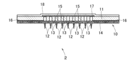
- FIG. 1 shows (1) a schematic cross-sectional view and (2) a partially enlarged view of a needle-like part of the microneedle structure of the present invention.
- FIG. 1 is a schematic partial cross-sectional view of a test patch using the microneedle structure of the present invention.
- (a) to (c) are explanatory diagrams showing the steps of a method for manufacturing a microneedle structure according to an embodiment.
- (a) to (c) are explanatory diagrams showing the steps of a method for manufacturing a microneedle structure according to an embodiment.
- FIG. 1 shows a microneedle structure 10 according to one embodiment of the present invention.
- the microneedle structure 10 includes a plurality of needle-shaped parts 12 spaced apart from each other at predetermined intervals on one side of a base material 11. Further, a plurality of holes 13 are formed in each of the needle portions 12 . A through hole 15 is formed in the base material 11 .
- the microneedle structure 10 is a test patch that absorbs body fluid from within the skin through the hole 13 of the needle-shaped part 12 and performs a test using the body fluid obtained through the base material 11, and the base material 11 and It can be used as a drug administration patch for administering a drug into the body through the skin through the hole 13 of the needle-shaped portion 12.
- body fluids include blood, lymph fluid, interstitial fluid, and the like.
- Needle-shaped portion The shape, size, formation pitch, and number of needle-like portions 12 can be appropriately selected depending on the intended use of the microneedle.
- the shape of the needle portion 12 include a cylindrical shape, a prismatic shape, a conical shape, a pyramid shape, and the like, and in this embodiment, it is a pyramid shape.
- the maximum diameter or maximum cross-sectional dimension of the needle-like portion 12 is, for example, 25 to 1000 ⁇ m, and the tip diameter or cross-sectional dimension of the tip is 1 to 100 ⁇ m.
- the height is, for example, 50 to 2000 ⁇ m.
- the needle-shaped parts 12 are provided in a plurality of rows in one direction of the base material 11, and a plurality of needle-like parts 12 are formed in each row and arranged in a matrix.
- the needle-shaped portion 12 is made of resin.
- the resin constituting the needle-shaped portion 12 is a low-melting resin having a weight average molecular weight of 25,000 or more, that is, a high-molecular-weight, low-melting resin.
- the low melting point resin is a thermoplastic resin that is solid at room temperature and has a melting point of 130° C. or lower.
- materials with a melting point of 40 to 120°C are particularly preferred, and materials with a melting point of 45 to 100°C are most preferred. Since it is solid at room temperature, the shape of the needle-like part 12 can be maintained at room temperature, and when the melting point is 130° C.
- the weight average molecular weight of the low melting point resin is 25,000 or more, preferably 40,000 to 200,000, more preferably 60,000 to 150,000. Within this range, the needle-shaped portion 12 can maintain the necessary strength. Further, when the weight average molecular weight of the low melting point resin is 25,000 or more, the water absorbency of the needle portion 12 is improved. Although the reason for this is not necessarily clear, it is presumed that by using a high molecular weight, low melting point resin, the structure of the pores 13 of the needle portion 12 is different from that when a low molecular weight, low melting point resin is used. Further, when the weight average molecular weight of the low melting point resin is 60,000 or more, the water absorbency of the needle part 12 can be further improved when the needle part 12 contains a water-insoluble hydrophilic resin described below. .
- the strength of the tip of the needle portion 12 obtained by including the high molecular weight, low melting point resin in this way is usually 100 mN or more, preferably 150 mN or more, and more preferably 200 mN or more.
- the tip strength of the needle-shaped portion 12 is a value measured by the procedure described in Examples described later.
- the needle part 12 is constructed using a low melting point resin having a weight average molecular weight of 25,000 or more, so that the strength of the needle part 12, particularly the tip strength of the needle part 12, is increased. For example, when the needle-like part 12 is pierced into the skin, damage to the needle-like part 12 can be suppressed.
- the high molecular weight, low melting point resin constituting the needle portion 12 may further be a water-insoluble resin. Being water-insoluble, when applied to a living body, it is not dissolved by water-containing fluids such as body fluids, and it is possible to maintain the shape of the microneedle structure 10 for a desired application time. Furthermore, as will be described later, minute holes 13 can be easily formed.
- water-insoluble resins include polyolefin resins such as polyethylene and ⁇ -olefin copolymers, olefin copolymer resins such as ethylene-vinyl acetate copolymer resins, polyurethane elastomers, and ethylene-ethyl acrylate copolymers.
- Water-insoluble low-melting point resins have hydrophilic functional groups such as hydroxyl groups, carboxyl groups, sulfonic acid groups, amine groups, and acetamide groups in portions other than the terminals in order to reduce solubility in water. Preferably not.
- the high molecular weight, low melting point resin constituting the needle portion 12 may further be a biodegradable resin.
- biodegradable resin is a plastic that is completely decomposed into CO2 and water by the action of microorganisms that exist in nature after use. can reduce the impact of
- aliphatic polyesters and derivatives thereof are preferably used, and further, homocopolymers of at least one monomer selected from the group consisting of glycolic acid, lactic acid, and caprolactone, or Examples include copolymers made of two or more types of monomers.
- polybutylene succinate (melting point: 84-115°C), aliphatic aromatic copolyester (melting point: 110-120°C), etc. can also be used as low-melting point biodegradable resins.
- the butylene succinate BioPBS provided by Mitsubishi Chemical Corporation, etc. can be used, and as the aliphatic aromatic copolyester, Ecoflex manufactured by BASF, etc. can be used.
- the biodegradable resin may be a resin whose monomer has an acid dissociation constant of 4 or more.
- the acid dissociation constant of the monomer is 4 or more, the influence on the living body when the microneedle structure 10 is applied to the living body can be reduced.
- the acid dissociation constant of the monomer is preferably 4.0 or more, more preferably 4.5 or more.
- the acid dissociation constant of the monomer is preferably 25 or less, more preferably 15 or less.
- an example of such a monomer constituting the biodegradable resin and having an acid dissociation constant of 4 or more is caprolactone.
- the constituent units of the monomers from which the acid dissociation constant is 4 or more preferably account for 70% by mass or more, and preferably 80% by mass or more of the total constituent units. The content is more preferably 90% by mass or more.
- the ratio of the low melting point resin to the total mass of the resin components contained in the needle part 12 should be 50% by mass or more from the viewpoint of efficiently obtaining the effect that the resin can be processed at low temperatures. is preferable, more preferably 65% by mass or more, and still more preferably 80% by mass or more.
- the needle-shaped part 12 may further contain a high melting point resin having a melting point higher than 130° C. within a range that does not impede the effect that the resin can be processed at low temperatures, and the high melting point resin includes polyglycolic acid. (melting point: 218°C), polylactic acid (melting point: 170°C), polyhydroxybutyric acid (melting point: 175°C), and other biodegradable resins.
- the resin constituting the needle portion 12 is a water-insoluble, high molecular weight, low melting point resin, a biodegradable resin, and a polyester having a monomer acid dissociation constant of 4 or more. Mention may be made of caprolactone or copolymers of caprolactone and other polymers.
- the needle-like part 12 contains a water-insoluble hydrophilic resin from the viewpoint of improving the water absorbency of the needle-like part 12.
- the water-insoluble hydrophilic resin is a polymeric substance that is insoluble in water and has a hydrophilic functional group. Since the water-insoluble hydrophilic resin is insoluble in water, it does not dissolve in water-containing fluids such as body fluids when applied to a living body, and maintains the shape of the microneedle structure 10 for a desired application time. It is possible to keep it. Moreover, by containing a water-insoluble hydrophilic resin, minute holes 13 can be easily formed in the needle-shaped portion 12 as described later.
- hydrophilic functional group examples include a hydroxyl group, a carboxyl group, a sulfonic acid group, an amine group, an acetamido group, and the like, with a hydroxyl group and a carboxyl group being preferred.
- the water-insoluble hydrophilic resin preferably has a hydrophilic functional group in its main chain or side chain.
- the carboxyl group may be in a carboxylate state in the presence of a counter ion such as a metal ion.
- the water-insoluble hydrophilic resin a resin having both a repeating unit having a hydrophilic functional group and a repeating unit not having a hydrophilic functional group may be used. However, in this case, it is preferable that the mass of the repeating unit having a hydrophilic functional group accounts for half or more of the mass of the resin. More preferably, the water-insoluble hydrophilic resin includes a resin in which all repeating units have hydrophilic functional groups.
- the equivalent weight of the hydrophilic functional group in the water-insoluble hydrophilic resin is, for example, 1,500 or less, preferably 1,100 or less, more preferably 900 or less, and even more preferably 500 or less.
- water-insoluble hydrophilic resins include fully saponified polyvinyl alcohol; water-insoluble polysaccharides such as cellulose, calcium alginate, chitin, and crosslinked hyaluronic acid.
- water-insoluble polysaccharides which are biologically derived substances are preferred from the viewpoint of affinity for living organisms, and cellulose is preferred from the viewpoint of keeping raw material costs low.
- the amount of water-insoluble hydrophilic resin contained in the needle part 12 is determined from the viewpoint of further improving the water absorbency of the needle part 12 and facilitating the preparation of a composition for forming the needle part 12. , preferably 4 parts by mass or more and 50 parts by mass or less, more preferably 5 parts by mass or more and 45 parts by mass or less, and 15 parts by mass or more and 40 parts by mass, based on 100 parts by mass of high molecular weight low melting point resin. It is more preferable that it is the following.
- the water-insoluble hydrophilic resin is usually not compatible with the low melting point resin and is present in the needle portion 12 in a state separated from the low melting point resin.
- the needle-shaped portion 12 may contain filler. By containing the filler in the needle-like portion 12, it is possible to further improve the mechanical strength of the needle-like portion 12.
- the filler is preferably contained in a dispersed state in the resin of the needle-shaped portion 12.
- the filler is preferably made of resin, and is preferably made of one selected from the group consisting of natural organic polymers or modified products thereof, and biodegradable resins.
- Fillers made of resin can also contain inorganic components, such as organic/inorganic hybrid fillers in which inorganic substances are attached to the surface of resin particles, but in consideration of the effect on living organisms, resin and It is preferable that it consists only of organic components, and more preferably that it consists only of resin.
- natural organic polymers include polysaccharides such as cellulose, and fillers made of natural organic polymers or modified products thereof include cellulose fibers, cellulose acetate true spherical particles, and the like.
- the polysaccharide the water-insoluble polysaccharide mentioned above may be contained in the form of particles in the needle-shaped body 12 to function as a filler.
- biodegradable resin those mentioned above can be used, but when using a biodegradable resin as a high molecular weight, low melting point resin, a biodegradable resin different from this biodegradable resin may be used.
- a biodegradable resin having a melting point exceeding 130° C. or having no melting point is preferable.
- Such biodegradable resins include polylactic acid (melting point: 170°C), polyglycolic acid (melting point: 218°C), polyhydroxybutyric acid (melting point: 175°C), and cellulose acetate diacetate (melting point: 230-300°C). ) etc.
- biodegradable resins such as cellulose butyrate diacetate also fall under the category of modified natural organic polymers.
- the filler is preferably made of a resin with a melting point exceeding 130°C or having no melting point. If the resin has a melting point exceeding 130° C., it will be difficult to soften at a temperature near the room temperature at which the microneedle structure 10 is used. Therefore, when the filler is made of a resin having a melting point of over 130° C., it is easy to obtain sufficient strength of the microneedle structure 10.
- the filler 12 is made of a resin with a melting point exceeding 130°C, by adding such a hard-to-melt resin in the form of a filler, the hard-to-melt resin can be added when mixed with a low-melting point resin.
- thermodegradable resins examples include polypropylene (melting point: 155°C), polybutylene terephthalate (223°C), polyethylene terephthalate (melting point: 260°C), Examples include polytetrafluoroethylene (melting point: 327°C), melamine resin (melting point: none), unmodified cellulose (melting point: none).
- the filler is preferably made of a resin having a glass transition temperature of 80°C or less. Since the filler is made of a resin with a glass transition temperature of 80° C. or lower, even when melting the resin constituting the needle portion 12 at a low temperature, the filler tends to soften during melting and form the needle shape. It becomes easily compatible with the resin constituting the portion 12. This makes it easier to improve the strength of the needle-shaped portion 12 to be manufactured. Note that when the resin contained in the filler is crosslinked, the polymer before crosslinking has a glass transition temperature of 80° C. or lower.
- Examples of resins having a glass transition temperature of 80°C or lower include polypropylene (Tg: 0°C), polybutylene terephthalate (Tg: 50°C), polyethylene terephthalate (Tg: 69°C), polymethyl methacrylate (Tg: 60°C), Examples include polylactic acid (Tg: 60°C), polyglycolic acid (Tg: 40°C), polyhydroxybutyric acid (Tg: 15°C), etc.
- it is polylactic acid, polyglycolic acid, polyhydroxybutyric acid, or a copolymer of these polymeric monomers.
- the filler is also preferably made of a resin having a glass transition temperature of ⁇ 10° C. or higher.
- the filler is more preferably made of a resin having a glass transition temperature of 10 to 80°C, and even more preferably made of a resin having a glass transition temperature of 30 to 75°C.
- the filler is preferably contained in an amount of 3 to 50% by mass, more preferably 5 to 43% by mass, and still more preferably 10 to 35% by mass, based on the mass of the entire needle portion 12. be.
- the content is 50% by mass or less, it becomes easy to maintain the shape of the needle-shaped portion 12, and workability during manufacturing also improves.
- the content is 3% by mass or more, it becomes easier to increase the strength.
- By containing the filler in an amount within this range it is easy to form the needle-like portion 12 with a desired porosity and maintain liquid permeability, while also increasing the strength of the needle-like portion 12 due to the filler. Become. Further, two or more types of fillers described above may be contained.
- the filler in the resin constituting the needle portion 12 so that the total amount of filler falls within the above content range.
- the content of the filler is 4 parts by mass or more and 50 parts by mass or less with respect to 100 parts by mass of the high molecular weight low melting point resin. It is preferably 5 parts by mass or more and 45 parts by mass or less, and even more preferably 15 parts by mass or more and 40 parts by mass or less.
- the shape of the filler includes plate-like (flake-like), fibrous, spherical, amorphous, etc., but fibrous is preferable. It is preferable that the shape of the filler is fibrous because it easily adapts to the molten resin constituting the needle-like part 12 and easily improves the strength of the obtained needle-like part 12.
- Examples of fillers having a fibrous shape include metal fiber fillers, carbon fibers, carbon nanofibers, and cellulose fibers.
- the filler has a shape other than fibrous, for example, when it is spherical or amorphous, the filler is made of a resin with a glass transition temperature of 80°C or less, so that the filler has a low melting point. Easily blends into the resin.
- the particle size of the filler is 0.3 to 150 ⁇ m, preferably 0.5 to 125 ⁇ m, and more preferably 1 to 100 ⁇ m.
- the particle diameter of the filler is the average of 7 values obtained by observing the filler in the microneedle structure 10 using a scanning electron microscope (SEM) and measuring the length of the longest part of the particle.
- SEM scanning electron microscope
- the needle-shaped portion 12 has a hole 13 formed therein as a flow path through which liquid flows.
- One or more holes 13 are formed in one needle-like section 12 and open at least one on the surface of the needle-like section 12 .
- the hole 13 may be formed in any way, for example, a single communicating hole may be provided mechanically, but it is preferable that the needle-shaped portion 12 has a porous structure as in this embodiment. . If the needle-shaped part 12 is formed so that at least a part thereof has a porous structure, body fluids or medical fluids can pass through the pores 13 of the porous structure, so it is not necessary to mechanically form a nano-order flow path. It is preferable that there is no such thing.
- the amount of flow can be reduced compared to when a single communicating hole is formed. It is possible to increase it.
- the surface area of the hole 13 with which a fluid containing water such as a body fluid or a medical solution comes into contact inside the needle-shaped body 12 is large. Therefore, by including the water-insoluble hydrophilic resin in the needle-like portion 12, the hydrophilicity of the surface of the hole portion 13 is increased, thereby making it easier to obtain the effect of improving the water absorbency of the needle-like portion 12.
- the needle-like part 12 is formed so that at least a part thereof has a porous structure, if the porous structure is not covered on a part or all of the side surface of the needle-like part, the needle-like part 12 A hole 13 is also opened on the side surface. In this case, the amount of liquid flowing can be increased compared to the case where only the tip of the needle portion 12 is opened.
- the needle portion 12 may become brittle, but in this embodiment, the needle portion 12 is made of a low melting point resin with a weight average molecular weight of 25,000 or more and a melting point of 130° C. or less. Since the shaped portion 12 is formed, it is possible to form the needle shaped portion 12 with high strength without becoming brittle.
- the porous structure may be formed simultaneously with the formation of the needle-shaped portion 12, or the protrusion 32 (not shown in FIG. 1, which will be described later) in which no porous structure is formed.
- a method of forming a porous structure in the protrusion 32 after the formation of the pores 13 is preferable from the viewpoint of making the pores 13 have a continuous structure.
- the protrusion 32 is formed by mixing two or more different materials, and then at least one material is removed to form the hole 13, thereby obtaining the porous needle-shaped part 12. That's fine.
- the filler is contained in a dispersed state in the resin of the needle-like part 12 according to such a method of forming a porous structure.
- the needle-like part 12 is made of high molecular weight polycaprolactone, and as described later, the protrusion part 32 is made of polycaprolactone, which is a water-insoluble resin, and a water-soluble material, and is immersed in water in the removal process.
- the pores 13 are formed by removing the soluble water-soluble material, and the water-insoluble resin that is insoluble in water remains, thereby forming the needle-shaped portion 12 having a porous structure.
- the hole 13 is a void formed by removing a water-soluble material from the protrusion 32 made of a water-insoluble high-molecular-weight low-melting resin and a water-soluble material, and body fluids and medical fluids pass through the hole 13. Passes through as a flow path. As shown in the cross section of the needle-shaped portion 12, a plurality of voids are formed by removing the water-soluble material and are communicated with each other. Depending on the hole 13 , a flow path is formed that communicates from the surface of the needle-shaped portion 12 to one side of the base material 11 .
- the size of the opening of the hole 13 is determined depending on the intended use of the microneedle structure 10, such as a test patch, but from the viewpoint of making it easier for liquid to pass through, the size of the opening is 0.1 to 50 mm. It is preferably 0.0 ⁇ m, more preferably 0.5 to 25.0 ⁇ m, and even more preferably 1.0 to 10.0 ⁇ m.
- the water-soluble material and its content are appropriately selected in the manufacturing process so as to have such an opening diameter.
- the needle-shaped part 12 is formed by removing the water-soluble material from the protrusion part 32 made of a water-insoluble high-molecular weight low-melting resin and a water-soluble material, but the present invention is not limited to this. It is also possible to form the needle portion 12 using a high molecular weight, low melting point resin. Alternatively, a porous structure may be formed using a foamed material or the like at the same time as the needle-like portion 12 is formed, or a porous structure may be formed by sintering a particulate composition containing a low melting point resin. .
- the needle-like portion 12 may have a base portion 14 provided over at least a region in which the needle-like portion 12 is formed between the needle-like portion 12 and one side of the base material 11 .
- the base 14 is provided in a layered manner over the entire one side of the base material 11 .
- the base portion 14 serves as a base for each needle-like portion 12 and has a hole 13 similarly to each needle-like portion 12 .
- the base portion 14 is formed to have a thickness of, for example, 0.1 to 500 ⁇ m. By having such a thickness, the strength of the base material 11 is increased, and preferable adhesiveness is obtained between the needle-shaped portion 12, the base portion 14, and the base material 11.
- the base part 14 also has a porous structure like the needle part 12, and it is more preferable to use the same resin so that it has the same porous structure as the needle part 12.
- a porous structure is used for the base 14, there is a channel formed therein through which the liquid flows, so there is no need to mechanically form the holes 13, and the liquid from the needle-like part 12 flows through the base 14. It is preferable that it can pass through the hole 13 and fill the through hole 15.
- the base 14 is made of the same high-molecular-weight, low-melting point resin as the needle-shaped part 12 and is formed by the same process. This is preferable because better adhesion can be obtained between the base material 11 and the base material 11 via the base portion 14.
- the base 14 is provided over the entire one side of the base 11, so that the base 14 is provided even in the part of the base 11 where the needle-shaped part 12 is not formed. 11, the strength of the microneedle structure 10 as a whole is further improved.
- the needle-like part 12 When the needle-like part 12 has a porous structure and the needle-like part 12 has the base 14, the needle-like part 12 is measured by the following test method in a state where the needle-like part 12 is composed only of the porous structure. It is preferable that the water absorption rate is 8.5% or more.
- Test method The needle portion is immersed in 10 ml of purified water in an environment of 25°C. The acicular part in the immersed state is placed in a reduced pressure environment of 0.09 MPa for 1 hour to allow water to enter the inside of the porous structure. Next, the needle-like part is taken out from the product and water droplets adhering to the surface are removed.
- the water absorption rate can be measured by the method described in the Examples below.
- the water absorption rate can be measured in the same manner after removing the base material 11 and making it into a needle-shaped part consisting only of a porous structure. Can be done.
- the water absorption rate is more preferably 13% or more, even more preferably 20% or more, even more preferably 28% or more.
- the upper limit of the water absorption rate is not particularly limited, but is usually about 50% or less.
- the needle-like part 12 has a hole 13 formed therein as a flow path through which liquid flows.
- the strength of the shaped portion 12 will be reduced.
- the strength of the needle-shaped portion 12 tends to further decrease. Therefore, in this embodiment, in order to support the needle-like part 12 from the root side of the needle-like part 12 and improve the strength of the microneedle structure 10, the microneedle structure 10 supports the needle-like part 12 from one side.
- a base material 11 is provided.
- the base material 11 is configured so that liquid can pass through it in the thickness direction. Being able to pass a liquid in the thickness direction of the base material 11 means that the base material 11 itself may be made of a liquid-permeable material, or the base material 11 may be made of a liquid-impermeable material. The liquid may be allowed to pass through the through hole 15 formed in the base material 11 in the thickness direction of the base material 11.
- the base material 11 made of a liquid-permeable material has a plurality of voids that communicate with each other, so that the back surface (the surface where the needle-shaped portion 12 is provided) is moved from one side (the surface where the needle-shaped portion 12 is provided) to the back surface (the surface where the needle-like portion 12 is provided).
- porous substrates include microscopic substrate pores formed therethrough on the opposite side of the substrate.
- the base material 11 made of such a liquid-permeable material may be in the form of a plate, but is preferably in the form of a sheet, which has a high ability to follow the skin.
- a base material made of a fibrous material that is easy to handle is used.
- the fibrous material in the present invention means fibers such as natural fibers and chemical fibers. Examples of the base material made of fibrous substances include nonwoven fabrics, woven fabrics, knitted fabrics, and paper made of these fibers.
- the base material 11 is made of a liquid-impermeable material and allows liquid to pass through the through-holes 15 in the thickness direction, liquid absorption of the base material 11 can be suppressed. Therefore, liquid can pass only through the through holes 15 in the base material 11. Therefore, the body fluid obtained from the needle-like part 12 or the drug solution transported to the needle-like part 12 does not seep into the base material 11, and the entire amount can be allowed to flow through the through-hole 15.
- the microneedle structure 10 is used as a test patch, body fluid can immediately pass through the base material 11, allowing for rapid analysis. Even when used as a drug administration patch, the drug solution does not seep out and the entire amount of the drug solution can be quickly supplied to the skin.
- the microneedle structure 10 is prepared by filling the through-holes with an absorbent material capable of absorbing liquid, as described in the international publication pamphlet WO2023/042525.
- the absorbent material may be a porous material.
- liquid-impermeable materials include resin films, metal-containing sheets, glass films, and the like.
- the metal-containing sheet include metal foil.
- a metal layer may be formed on a resin film having low water resistance by vapor deposition or the like to improve water resistance and may be used as the metal-containing sheet.
- it may be a material that is not liquid-impermeable, such as a nonwoven fabric or paper, or a laminated resin film made by laminating a water-insoluble resin on these materials so that the entire film is impermeable to liquid.
- the base material 11 is made of a liquid-impermeable resin film.
- the resin used for such a resin film is one selected from the group consisting of polybutylene terephthalate, polyethylene terephthalate, polyethylene, polypropylene, ethylene-vinyl acetate copolymer, vinyl chloride, acrylic resin, polyurethane, and polylactic acid. It is also possible to use resins with relatively low heat resistance and heat-resistant resins such as polyimide, polyamideimide, and polyethersulfone.
- a low melting point resin is used as the resin forming the needle portion 12, and the composition containing the low melting point resin can be processed at low temperatures, thereby avoiding exposing the base material 11 to high temperatures. Can be done. Therefore, even with a resin film using a resin with low heat resistance, problems such as deformation of the base material are unlikely to occur.
- the base material 11 may be a single layer or may have a structure in which multiple layers are laminated.
- the base material 11 may be formed by laminating a porous base material 11 such as a nonwoven fabric and a liquid-impermeable base material 11 in which through-holes are formed.
- the resin film may be a composite film obtained by impregnating a nonwoven fabric or a cloth with a resin.
- the thickness of the base material 11 is preferably 3 to 200 ⁇ m, more preferably 10 to 140 ⁇ m, and even more preferably 30 to 115 ⁇ m. When the thickness is 3 ⁇ m or more, it is easy to maintain the strength as the base material 11, and when the thickness is 200 ⁇ m or less, the followability to the skin is improved and the liquid transport time can be shortened. It is possible.
- An adhesive layer 16 is provided on one side of the base material 11 on which the needle-shaped portion 12 is formed. Thereby, the adhesiveness between the needle-shaped portion 12 and the base material 14 and the base material 11 can be improved.
- a pressure sensitive adhesive is preferable, and examples thereof include an acrylic adhesive, a silicone adhesive, a rubber adhesive, and more preferably an acrylic adhesive.
- the adhesive layer 16 is provided on the base material 11, in the method for manufacturing a microneedle structure described below, the solid composition 31 is bonded to the base material 11 in advance, and the solid composition 31 is bonded to the base material 11 in advance.
- the microneedle structure 10 can be easily obtained by putting the object 31 into a mold and heating and pressing it in a heating and pressing step.
- the adhesive layer 16 When the adhesive layer 16 is provided on the base material 11, a gap may be created between the base material 11 and the needle-like part 12, and liquid may leak out, or the adhesive layer may cause the base material 11 and the needle-like part 12 to There is a concern that the passage of liquid between the two may be obstructed. Therefore, it is preferable to provide the adhesive layer 16 so as to surround the region through which the liquid should pass in the base material 11, while providing a region in which the adhesive layer 16 is not formed in the central portion. Although such an effect cannot be obtained, a first primer layer (not shown) may be used instead of the adhesive layer 16 for the purpose of improving the adhesiveness between the needle-shaped portion 12 and the base material 11. It may be provided. Further, even when the base material 11 has the adhesive layer 16, a first primer layer as an intermediate layer may be provided between the base material 11 and the adhesive layer 16. Examples of the primer layer include an acrylic primer layer, a polyester primer layer, and the like.
- acrylic pressure-sensitive adhesive one containing an acrylic polymer obtained by polymerizing a monomer whose main component is an acrylic acid alkyl ester can be used.
- the acrylic polymer may be a copolymer of an acrylic acid alkyl ester and other monomers.
- Other monomers include acrylic esters other than alkyl acrylates, such as acrylic esters having a hydroxyl group, acrylic esters having a carboxyl group, and acrylic esters having an ether group, as well as vinyl acetate, styrene, etc. Examples include monomers other than acrylic esters.
- the acrylic polymer may be crosslinked by a reaction between a functional group derived from the above-mentioned acrylic ester having a hydroxyl group, acrylic ester having a carboxyl group, etc., and a crosslinking agent.
- the acrylic pressure-sensitive adhesive may contain a tackifier, a plasticizer, an antistatic agent, a filler, a curable component, and the like.
- a coating liquid for obtaining an acrylic pressure-sensitive adhesive either a solvent type or an emulsion type can be used.
- the shape of the through-holes 15 formed in the base material 11 is not particularly limited, but a structure in which a plurality of through-holes with small diameters are provided is preferable from the viewpoint of ensuring sufficient flow rate while generating capillary action. .
- the diameter of the through hole 15 is, for example, 2 mm or less, preferably 0.05 to 1 mm, and more preferably 0.1 to 0.8 mm.
- the method of forming the through hole 15 is not particularly limited, and may be formed by punching or laser drilling, for example.
- the liquid when transporting the liquid from the needle-like part 12 , since the base material 11 has liquid impermeability, the liquid does not seep into the base material 11 and can be transported through the through hole 15 . Since the liquid is distributed in the thickness direction of the base material 11, the transportation distance is short, and when configured as a detection patch, detection can be performed at a high analysis speed, and when configured as a drug administration patch, , it is possible to administer the drug solution early.
- the total area of each through hole 15 is preferably 0.05 to 15% in total, more preferably 0.05 to 15% of the area of the area on the base material 11 in which the through hole 15 is provided. is 0.75 to 10%, more preferably 1 to 5%.
- the total area of the through holes 15 is 15% or less of the area of the above region of the base material 11, the rigidity of the base material 11 can be easily ensured.
- the total area of the through holes 15 is 0.05% or more of the area of the above region of the base material 11, body fluid can be more efficiently acquired via the base material 11.
- the base 14 When the base 14 is formed in the microneedle structure 10, the base 14 is directly adhered to one side of the base material 11, and the base 14 is formed integrally with the needle-like part 12, so that the needle-like part 12 is provided on the base material 11 without using an adhesive or the like, the holes 13 have good communication, and liquid can easily pass through.
- the solid composition 31 can be heated in the formation step of the microneedle structure manufacturing method described below. It can be obtained by adhering to the base material 11 or by a similar adhesion method using heat. Note that in this embodiment, the base portion 14 is provided over the entire surface of the base material 11, but the present invention is not limited thereto.
- the base portion 12 is formed at least in the region where the needle-shaped portion 12 is formed. Even if the base 14 is directly adhered to one side of the base material 11, the first primer layer is provided on the base material 11 instead of the adhesive layer 16 as described above, and the base material 14 may be adhered to the base material 11 through the first primer layer, or through another layer other than the adhesive layer 16 and the first primer layer.
- the microneedle structure 10 formed in this manner can be used as a test patch or a drug administration patch.
- an analysis sheet 17 is arranged so as to face the needle-shaped part 12 in the area where the through-hole 15 is formed in the base material 11 of the obtained microneedle structure 10.
- a tape 18 is laminated to cover the analysis sheet 17.
- a drug administration member is placed in place of the analysis sheet 17 so as to face the needle portion 12 at a position covering the area where the through holes 15 of the base material 11 of the obtained microneedle structure 10 are formed.
- the tape 18 may be laminated to cover the drug administration member.
- the strength of the needle part 12 is high, so it is possible to penetrate the skin without damaging the needle part 12, and the structure of the needle part 12 can be inserted into the body. This is preferable because it can prevent material from remaining.
- the tape 18 for fixing the analysis sheet 17 or the drug administration member onto the base material 11 may be an adhesive tape provided with an adhesive layer.
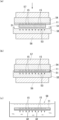
- 3 and 4 show a method for manufacturing a microneedle structure and a test patch 2 according to an embodiment of the present invention.
- a water-insoluble high molecular weight, low melting point resin and a water-soluble material for forming the holes 13 are melted and filled into a mold (filling step), and the filled mixture is solidified.
- the solid composition 31 is adhered to the base material 11 (adhesion step), then the solid composition 31 is heated and pressurized to form the protrusion 32 (formation step), and then the water-soluble material is removed from the protrusion 32. (removal process), and the protrusion 32 is made into the needle-like part 12. This will be explained in detail below.
- a mixture 33 is prepared by heating and melting a composition containing a water-insoluble polymeric low-melting resin, a water-soluble material, and any optional components (for example, a water-insoluble hydrophilic resin or filler). do.
- the shape of the high molecular weight, low melting point resin is not particularly limited, but a commonly used pellet shape can be used.
- the heating temperature can be set relatively low. Therefore, in the subsequent formation process, even if the base material 11 is heated together with the solid composition 31 to form the protrusions 32, it is heated at a low temperature. The base material 11 does not soften, deform, or burn, and there is a high degree of freedom in selecting the base material 11.
- the high molecular weight low melting point resin and the water-soluble material can be sufficiently kneaded by kneading using a kneader.
- the mixture 33 is preferably in a molten state. If heating at a lower temperature is important, the mixture 33 may be softened to the extent that it adheres to the base material 11, but in order to reduce the manufacturing time, it is preferable to melt the water-insoluble material as described above. It is preferable to heat at a temperature higher than the melting point of the low melting point resin to be started.
- the water-soluble material a water-soluble material having at least a melting point higher than room temperature is preferable.
- the water-soluble material may be organic or inorganic, and includes sodium chloride, potassium chloride, mirabilite, sodium carbonate, potassium nitrate, alum, sugar, and water-soluble resins.
- the water-soluble resin is preferably a water-soluble thermoplastic resin, and preferably has a melting point higher than room temperature. Examples of water-soluble thermoplastic resins include hydroxypropylcellulose, polyvinylpyrrolidone, and the like, in addition to the biodegradable resins described below.
- the water-soluble thermoplastic resin is more preferably a biodegradable resin in consideration of its effect on the human body.
- Such biodegradable resins include at least one selected from the group consisting of polyalkylene glycols such as polyethylene glycol and polypropylene glycol, polyvinyl alcohol, collagen, and mixtures thereof, with polyalkylene glycols being particularly preferred.
- the molecular weight of the polyalkylene glycol is, for example, preferably 200 to 4,000,000, more preferably 600 to 500,000, and particularly preferably 1,000 to 100,000.
- polyalkylene glycols it is preferable to use polyethylene glycol.
- the melting point of the high molecular weight low melting point resin and the water soluble material are determined so that both the high molecular weight low melting point resin and the water soluble material can be easily melted at the same heating temperature when preparing the mixture 33. It is preferable that the difference in melting point is 40°C or less, more preferably 30°C or less.
- the water-insoluble material and the water-soluble material are preferably mixed at a mass ratio of 9:1 to 1:9, more preferably 8.5:1.5 to 3:7, and 8:1 to 1:9. Particularly preferred is a mixing ratio of 2 to 5:5.
- the needle-shaped portion 12 can be formed with a desired porosity, and it becomes easier to achieve both liquid permeability and strength of the needle-shaped portion 12.
- the mixture 33 is injected into a solid composition recess 42 formed in a solid composition mold 41, as shown in FIG. 3(a). It is sufficient that the solid composition recess 42 has a shape and capacity that can store a desired amount of the mixture 33.
- the material of the solid composition mold 41 is not particularly limited, but it should be made of, for example, a silicone compound that is easy to make an accurate mold and easy to peel off the solidified composition 31. is preferable, and in this embodiment it is made of polydimethylsiloxane.
- the recess 42 for solid composition is A solid composition sheet 43 made of, for example, polydimethylsiloxane (PDMS) is placed on the top surface as a lid.
- PDMS polydimethylsiloxane
- the base material 11 has an adhesive layer 16 in this embodiment, and the adhesive layer 16 may be formed by coating or application, but in this embodiment, the base material 11 has an adhesive layer 16 in a predetermined area. Adhesive tape is used as the base material 11. Then, a through hole 15 is formed in the base material 11.
- the method of forming the through hole 15 is not particularly limited, and may be formed by punching or laser drilling, for example.
- the solid composition 31 is attached to the adhesive layer 16 of the base material 11 to integrate the base material 11 and the solid composition 31.
- the solid composition 31 is adhered to the base material 11 in advance, and the base material 11 and the solid composition 31 are placed in a mold and heated as described below.
- the microneedle structure 10 can be easily obtained. Further, since the base material 11 and the solid composition 31 are integrated, handling such as transportation becomes easier.
- the solid composition 31 including the base material 11 is placed in the recess 51 of the mold 52 having the recess 51.
- a protrusion forming recess 53 is also provided at the center of the bottom surface of the recess 51 .
- the solid composition 31 is placed on the bottom surface of the recess 51, that is, on the protrusion forming recess 53.
- the protrusion forming recess 53 is for forming the needle-like part 12 and is formed in a shape and size corresponding to the needle-like part 12.
- the lid 54 of the mold 52 is installed on the other side (back side) of the base material 11. This lid 54 is also made of polydimethylsiloxane, for example.
- the heating step is for forming the protrusions 32 and the like in a desired shape, and heating and pressing may be performed all at once, but as in the present embodiment, the solid composition is heated in the recess 51 of the mold 52. 31, a preliminary process for starting melting of the solid composition 31 including the base material 11, and a book for sufficiently filling the recesses 51 etc. with the molten solid composition 31. It is preferable that it consists of a step.
- the mold 52 and the lid 54 are placed between the base material 11 and the solid composition. An object 31 is held between the two. Then, in this state, the mold 52 and the lid 54 are placed on the lower stage 56, and the upper stage 57 is installed on the mold 52 and the lid 54.
- the heating conditions in the preliminary step and the main step it is sufficient to heat at 40° C. or higher and 180° C. or lower, which has little effect on the base material 11, preferably at 55 to 180° C., and 70 to 170° C. It is more preferable to heat at °C.
- the solid composition 31 is heated at a temperature at which it can be melted. Note that in order to heat the solid composition 31, at least one of the lower stage 56 and the upper stage 57 may be heated, or both may be heated, but it is preferable to heat both.
- the lower stage 56 In order to quickly fill the solid composition 31 containing a high molecular weight, low melting point resin into the recesses 51 etc., it is preferable to set the lower stage 56 to a high temperature, for example, set the lower stage to a temperature in the range of 120 to 180°C Good too.
- the temperature of the upper stage 57 is determined from the viewpoint of suppressing deformation of the base material due to heat while obtaining the effect of improving the adhesiveness between the needle-shaped portion 12 or the base portion 14 and the base material 11, as will be described later. , preferably in the range of 70 to 110°C. In this step, heating may be maintained after the preliminary step, and the temperature may be changed as appropriate.
- the mold 52 is pressed (pressurized) between the upper stage 57 and the lower stage 56.
- the pressure in this preliminary step is preferably 0.1 to 5.0 MP. With the pressure in this range, the solid composition 31 can be melted in a short time, and the molten solid composition 31 can be quickly filled into the recesses 51 and the like. Then, by holding it for 10 seconds to 10 minutes, the solid composition 31 becomes in a molten state.
- the pressurizing conditions may be changed between the preliminary step and the main step. For example, in this step, pressurization can be performed at a higher pressure or for a longer time than in the preliminary step.
- the solid composition 31 is sufficiently melted and filled into the recesses 51 and the protrusion forming recesses 53. Furthermore, if the obtained needle-like part 12 or base part 14 has a porous structure, the adhesion area of the needle-like part 12 or base part 14 to the base material 11 becomes small, which is disadvantageous for the adhesion between them. By heating in the forming step in a state where the base material 11 and the solid composition 31 are adhered to each other, the adhesion between the needle-shaped portion 12 or the base portion 14 and the base material 11 can be improved.
- the mold 52 is removed from the lower stage 37, and the molten solid composition 31 is held at -10 to 3°C for 1 to 60 minutes (refrigeration solidification step) to solidify it by refrigeration.
- the protrusions 32 and the like having a shape corresponding to the protrusion forming recess 53 and having high transferability are formed.
- the cleaning liquid in this removal process contains water, and in the removal process, as shown in FIG. This is done by letting it stand still.
- the cleaning liquid 58 only needs to contain water, and may be a mixed solvent of water and alcohol, for example.
- holes 13 are formed in the protrusions 32 and the like, and needle-like parts 12 made of the remaining high molecular weight, low melting point resin are formed.
- water-soluble material is also removed from the molten solid composition 31 that had adhered to one side of the base material 11 by filling the recess 51, so that the base portion 14 is also removed. formed as the same porous structure. Thereby, the microneedle structure 10 of this embodiment is obtained.
- test patch 2 is arranged at a predetermined position on the back side of the base material 11 of the obtained microneedle structure 10 and laminating the tape 18 so as to cover the analysis sheet 17 (installation process).
- the lamination method can be a conventionally known method. For example, after placing the analysis sheet 17 on the back side of the base material 11, a commonly used rubber adhesive, acrylic adhesive, silicone
- the test patch 2 can be manufactured by laminating an adhesive tape 18 in which an adhesive layer such as a type adhesive is formed on a tape base material. Drug delivery patches can also be manufactured by similar methods.
- the solid composition 31 contains a water-soluble material and a water-insoluble high molecular weight low melting point resin, but the solid composition 31 contains at least a resin.
- the composition does not contain a solvent, so discoloration and deformation of the base material 11 can be suppressed, which is preferable.
- the order of the adhesion process and the formation process may be changed, and the adhesion process may be performed in parallel with the formation process. That is, the solid composition 31 with a base material may be obtained by filling the concave portion 42 with the mixture 33 and placing the base material 11 on the mixture 33 and performing an adhesion process before solidifying it.
- the needle-like part 12 is formed using a water-insoluble high-molecular-weight, low-melting-point resin.
- a water-insoluble high-molecular-weight, low-melting-point resin there are no particular limitations on the method for producing the holes 13 as long as a melting point resin is used.
- the mold 2 is filled with particulate high-molecular-weight, low-melting point resin, etc., and sintered at a temperature higher than the melting point of the low-melting point resin, resulting in a porous structure composed of many voids between the particles.
- a microneedle structure having the following may be obtained.
- the forming step and the bonding step are performed simultaneously, it is possible to suppress deformation and deterioration of the base material 11 by providing the base material 11 with a layer made of a heat-resistant resin.
- a high-molecular-weight, low-melting-point resin to form the needle-like portions 12, there is no need to heat at high temperatures, resulting in low cost and good workability.
- the base material 11 is not deformed or softened, and the degree of freedom in selecting the base material 11 can be increased.
- the needle-like part 12 is formed using a water-insoluble material in order to easily form the hole 13 by removing the water-soluble material, but the method for producing the needle-like part 12 is not particularly limited.
- a liquid composition containing a water-soluble material, a water-insoluble material, and a solvent is formed, the solvent is evaporated, a composition other than the solvent is filled into the protrusion-forming recess, and the composition is dried.
- a method of forming a protrusion may be used.
- a liquid composition containing a water-soluble material and a water-insoluble material is prepared to have a viscosity of 0.1 to 1000 mP ⁇ s on the base material 11 using a dispenser or the like.
- a method may also be used in which the needle-like portion 12 is formed by dropping the liquid dropwise.
- the weight average molecular weight is the weight average molecular weight in terms of a standard substance: polystyrene, measured using gel permeation chromatography (GPC) under the following conditions (GPC measurement).
- GPC measurement gel permeation chromatography
- a sample for GPC measurement was prepared according to the following procedure. First, 1 g of polycaprolactone (PCL) used in Examples and Comparative Examples and 9 g of tetrahydrofuran (THF, manufactured by Fuji Film Wako Pure Chemical Industries, Ltd.) were added to a screw tube, shaken to completely dissolve, and a 10% PCL solution was added. Create.
- PCL polycaprolactone
- THF tetrahydrofuran
- Example 1 As water-soluble materials, 3 g of polyethylene glycol (PEG) (weight average molecular weight 4,000, melting point 40°C) and 7 g of pelleted polycaprolactone (weight average molecular weight 80,000) were added to Labo Plastomill 4C150 (Toyo Seiki Co., Ltd.) The mixture was heated and kneaded at 170°C. In this way, mixture 33 was prepared. A solid composition mold 42 made of polydimethylsiloxane is prepared, and a recess 42 with a square opening of 15 mm x 15 mm on each side and a depth of 1.5 mm is formed in the solid composition mold 41. It had been. The mixture 33 was injected so as to fill the concave portions 42 of the mold 41 for solid composition.
- PEG polyethylene glycol
- pelleted polycaprolactone weight average molecular weight 80,000
- a solid composition mold lid (sheet made of polydimethylsiloxane) 43 was placed on the solid composition mold 41, and the surface of the solid composition 31 was flattened. This state was maintained at 3° C. for 5 minutes, and the molten mixture 33 solidified into a solid, and was separated from the solid composition mold 41 to obtain a solid composition 31.
- a mold 52 having a concave portion 53 for forming a protrusion was prepared.
- the mold 52 was made of polydimethylsiloxane, and had a protrusion-forming recess 53 formed on its surface having a recess 51 as described in detail below.
- ⁇ Shape of the recess for forming a protrusion Square pyramid shape with a square cross section ⁇ Length of one side of the maximum cross section of the recess for forming a protrusion: 500 ⁇ m ⁇ Height of recess for forming protrusion: 900 ⁇ m ⁇ Pitch of recesses for forming protrusions: 1000 ⁇ m ⁇ Number of recesses for forming protrusions: 13 columns and 13 rows, total 169 ⁇ Size of area where recesses for forming protrusions are formed: 15 mm square ⁇ Arrangement of recesses for forming protrusions: Square grid pattern
- the mold 52 is placed on the lower stage 56 of a heating press machine (AH-1T, manufactured by As One Corporation), and the solid composition 31 with the base material 11 is placed on the mold 52 so as to face the recess 51. Then, a 30 mm square polydimethylsiloxane sheet (lid 54) was placed on top of it, and while heating at the lower stage setting heating temperature of the heating press machine: 140°C and the upper stage setting heating temperature: 140°C. A preliminary step was performed by pressing at 2 MPa for 3 minutes. Thereafter, this step was carried out by pressing at 4 MPa for 30 seconds while maintaining the temperature of the hot press machine and heating it. Further, the base material 11 and the molten composition contained in the lid 54 and the mold 52 were stored in a refrigerator at 3° C.
- a heating press machine As One Corporation
- the base material 11 was peeled off from the mold 52, and the base material 11 and the formed projections 32 and the like were immersed in purified water at 23° C. for 24 hours to dissolve and remove the water-soluble material. Thereafter, the base material 11 and the molded solid composition 31 were left in a drying oven (30° C.) for 5 hours to evaporate water and dry, thereby obtaining the microneedle structure 10.
- Example 2 As the resin constituting the needle portion 12, 7 g of pellet-shaped polycaprolactone (weight average molecular weight 40,000) having a different molecular weight from that in Example 1 was used, and the temperature of the heating step in the forming step was 110° C. A microneedle structure 10 was obtained in the same manner as in Example 1 except for this.
- Example 1 As the resin constituting the needle-shaped portion, 7 g of pelleted polycaprolactone (weight average molecular weight 10,000) having a different molecular weight from that in Example 1 was used, and the temperature of the heating step in the forming step was 110°C. A microneedle structure was obtained in the same manner as in Example 1, except that the pressurization time in the preliminary step was 1 minute and 30 seconds.
- microneedle structures obtained in Examples 1 and 2 and Comparative Example 1 were evaluated for microneedle array transferability and microneedle tip strength as described below.
- Measurement of the force applied to the attachment was started. At this time, the measurement temperature was 23° C. and the relative humidity was 50%.
- the measurement temperature was 23° C. and the relative humidity was 50%.
- the measured force is output, at the point when a drop in force is first observed, read the maximum value of the force indicated at the position before the drop in force, or when the drop distance of the attachment reaches 100 ⁇ m. If no decrease in force was observed before reaching the point, the force value was read when the attachment reached a descending distance of 100 ⁇ m, and that value was taken as the tip strength of the needle-shaped portion.
- Table 1 shows the evaluation results of Examples 1 and 2 and Comparative Example 1. (Table 1)
- the microneedle array transferability evaluation was A.
- the microneedle tip strength was less than 100 mN, and the evaluation was C.
- the strength of the needle portion 12 is increased by using a low melting point resin with a high molecular weight (weight average molecular weight of 25,000 or more).
- Example 3 A microneedle structure 10 was obtained in the same manner as in Example 1 except that the following points were changed.
- the microneedle structure 10 obtained in this example does not have the base material 11.
- the lid 54 was placed directly on the solid composition 31 without adhering the base material 11 to the solid composition 31.
- the heating temperature setting for the lower stage of the heating press machine was 115°C
- the heating temperature setting for the upper stage was 105°C
- the preliminary process time was changed to 1 minute 30 seconds (main process time remains unchanged).
- the conditions for immersing the molded solid composition 31 in purified water were changed to 40°C purified water for 24 hours
- the conditions for drying the molded solid composition 31 were changed to 40°C for 24 hours.
- Example 4 A microneedle structure 10 was prepared in the same manner as in Example 3, except that 7 g of pelleted polycaprolactone (weight average molecular weight 40,000) having a different molecular weight from Example 3 was used as the resin constituting the needle portion 12. I got it.
- Example 2 A microneedle structure was obtained in the same manner as in Example 3, except that 7 g of pelleted polycaprolactone (weight average molecular weight 10,000), which had a different molecular weight from Example 3, was used as the resin constituting the needle part. Ta.
- Example 5 When preparing Mixture 33, 0.5 g of ARBOCEL Ultrafine Cellulose (average particle size: 6-12 ⁇ m, manufactured by Rettenmeyer Japan) was added as a filler made of cellulose (water-insoluble hydrophilic resin). A microneedle structure 10 was obtained in the same manner as in Example 3.
- Example 6 A microneedle structure 10 was obtained in the same manner as in Example 5 except that the amount of filler added was changed to 2.0 g.
- Example 7 When preparing Mixture 33, micro-cellulose was prepared in the same manner as in Example 4, except that 0.5 g of ARBOCEL Ultrafine Cellulose (average particle size: 6-12 ⁇ m, manufactured by Rettenmeyer Japan) was added as a filler made of cellulose. A needle structure 10 was obtained.
- ARBOCEL Ultrafine Cellulose average particle size: 6-12 ⁇ m, manufactured by Rettenmeyer Japan
- Example 8 A microneedle structure 10 was obtained in the same manner as in Example 7 except that the amount of filler added was changed to 2.0 g.
- microneedle structures (acicular portions without a base material) obtained in Examples 3 to 8, Comparative Example 2, and Reference Examples 1 and 2 were evaluated for water absorption as follows.
- the weight of the needle-shaped sample before water absorption was measured.
- the sample was placed in a tray (balance dish, non-electrified, manufactured by As One Corporation) in an environment of 25° C., and 10 ml of purified water was poured to immerse the sample.
- the tray was then placed in a reduced pressure environment of 0.09 MPa for 1 hour to allow water to penetrate into the porous structure of the sample.
- the sample was then removed from the tray and water droplets adhering to the surface were removed. Specifically, water droplets on the surface of the needle-like portion on the side where the needles were formed were removed by blowing them off with an air blow gun.
- Water absorption rate (%) (Weight of sample after water absorption - Weight of sample before water absorption) ⁇ Weight of sample before water absorption x 100
- Example 2 The evaluation results are shown in Table 2.
- the "addition amount" of the water-insoluble hydrophilic resin is a value expressed as a percentage of the mass ratio of the water-insoluble hydrophilic resin to the total mass of the low-melting point resin and the water-soluble resin.
- Table 2 The water absorption rates of Example 3 and Example 2 were higher than those of Comparative Example 2, and it was confirmed that the higher the molecular weight of the low melting point resin, the higher the water absorption rate.
- Examples 5 and 6 and Examples 7 and 8 compared to Examples 3 and 4 in which the molecular weight of the low melting point resin is the same, by containing cellulose, which is a water-insoluble hydrophilic resin, Water absorption rate increased significantly. Even in these cases, Examples 5 and 6, in which the weight average molecular weight of the low melting point resin is 80,000, have a higher water absorption than Examples 7 and 8, and Reference Examples 1 and 2, which contain the same amount of cellulose. tended to be higher.
- microneedle structure of the present invention can be used as a test patch, for example, by placing an analysis sheet on the back side and laminating it with tape.
Landscapes
- Health & Medical Sciences (AREA)
- Life Sciences & Earth Sciences (AREA)
- General Health & Medical Sciences (AREA)
- Engineering & Computer Science (AREA)
- Veterinary Medicine (AREA)
- Public Health (AREA)
- Animal Behavior & Ethology (AREA)
- Dermatology (AREA)
- Heart & Thoracic Surgery (AREA)
- Biomedical Technology (AREA)
- Hematology (AREA)
- Medical Informatics (AREA)
- Anesthesiology (AREA)
- Surgery (AREA)
- Pathology (AREA)
- Physics & Mathematics (AREA)
- Chemical & Material Sciences (AREA)
- Epidemiology (AREA)
- Biophysics (AREA)
- Molecular Biology (AREA)
- Medicinal Chemistry (AREA)
- Pharmacology & Pharmacy (AREA)
- Analytical Chemistry (AREA)
- Biochemistry (AREA)
- General Physics & Mathematics (AREA)
- Immunology (AREA)
- Vascular Medicine (AREA)
- Media Introduction/Drainage Providing Device (AREA)
- Medicinal Preparation (AREA)
- Materials For Medical Uses (AREA)
Priority Applications (5)
| Application Number | Priority Date | Filing Date | Title |
|---|---|---|---|
| US18/880,051 US20260014359A1 (en) | 2022-06-30 | 2023-06-30 | Microneedle structure |
| JP2024530989A JPWO2024005176A1 (https=) | 2022-06-30 | 2023-06-30 | |
| DE112023002850.8T DE112023002850T5 (de) | 2022-06-30 | 2023-06-30 | Mikronadelstruktur |
| KR1020247040425A KR20250029788A (ko) | 2022-06-30 | 2023-06-30 | 마이크로 니들 구조체 |
| CN202380050311.6A CN119451722A (zh) | 2022-06-30 | 2023-06-30 | 微针结构体 |
Applications Claiming Priority (4)
| Application Number | Priority Date | Filing Date | Title |
|---|---|---|---|
| JP2022-106672 | 2022-06-30 | ||
| JP2022106672 | 2022-06-30 | ||
| JPPCT/JP2023/013269 | 2023-03-30 | ||
| PCT/JP2023/013269 WO2023190911A1 (ja) | 2022-03-31 | 2023-03-30 | マイクロニードル構造体及びマイクロニードル構造体の製造方法 |
Publications (1)
| Publication Number | Publication Date |
|---|---|
| WO2024005176A1 true WO2024005176A1 (ja) | 2024-01-04 |
Family
ID=89382533
Family Applications (1)
| Application Number | Title | Priority Date | Filing Date |
|---|---|---|---|
| PCT/JP2023/024316 Ceased WO2024005176A1 (ja) | 2022-06-30 | 2023-06-30 | マイクロニードル構造体 |
Country Status (7)
| Country | Link |
|---|---|
| US (1) | US20260014359A1 (https=) |
| JP (1) | JPWO2024005176A1 (https=) |
| KR (1) | KR20250029788A (https=) |
| CN (1) | CN119451722A (https=) |
| DE (1) | DE112023002850T5 (https=) |
| TW (1) | TW202408614A (https=) |
| WO (1) | WO2024005176A1 (https=) |
Cited By (2)
| Publication number | Priority date | Publication date | Assignee | Title |
|---|---|---|---|---|
| WO2026071015A1 (ja) * | 2024-09-30 | 2026-04-02 | リンテック株式会社 | マイクロニードル構造体の製造方法及びマイクロニードル構造体 |
| WO2026071014A1 (ja) * | 2024-09-30 | 2026-04-02 | リンテック株式会社 | マイクロニードル構造体及びその製造方法 |
Families Citing this family (1)
| Publication number | Priority date | Publication date | Assignee | Title |
|---|---|---|---|---|
| TWI898477B (zh) * | 2024-03-12 | 2025-09-21 | 怡定興生醫股份有限公司 | 透水微針貼片 |
Citations (7)
| Publication number | Priority date | Publication date | Assignee | Title |
|---|---|---|---|---|
| WO2006080508A1 (ja) * | 2005-01-31 | 2006-08-03 | Bioserentach Co., Ltd. | 経皮吸収製剤、経皮吸収製剤保持シート、及び経皮吸収製剤保持用具 |
| JP2007037885A (ja) * | 2005-08-05 | 2007-02-15 | Naoya Miyano | 経皮性薬剤配送装置及び経皮性薬剤配送方法並びに経皮性薬剤配送装置用針装置の製造方法 |
| WO2011010605A1 (ja) * | 2009-07-23 | 2011-01-27 | 久光製薬株式会社 | マイクロニードルアレイ |
| JP2017000724A (ja) * | 2015-06-05 | 2017-01-05 | 国立大学法人東北大学 | マイクロニードル及びマイクロアレイ並びにその製造方法 |
| JP2019058712A (ja) * | 2013-10-30 | 2019-04-18 | 株式会社 メドレックス | 薬剤でコーティングされたマイクロニードルアレイの製造方法 |
| KR102042572B1 (ko) * | 2017-09-29 | 2019-12-02 | 아이큐어 주식회사 | 비패치형 마이크로 니들 디바이스용 마이크로 구조체 및 비패치형 마이크로 니들 디바이스 |
| JP2020032211A (ja) * | 2013-07-16 | 2020-03-05 | スリーエム イノベイティブ プロパティズ カンパニー | 斜角開口部を有する中空マイクロニードル |
Family Cites Families (1)
| Publication number | Priority date | Publication date | Assignee | Title |
|---|---|---|---|---|
| JP2014094171A (ja) | 2012-11-09 | 2014-05-22 | Canon Inc | マイクロニードルおよびマイクロニードルアレイ |
-
2023
- 2023-06-30 JP JP2024530989A patent/JPWO2024005176A1/ja active Pending
- 2023-06-30 TW TW112124522A patent/TW202408614A/zh unknown
- 2023-06-30 KR KR1020247040425A patent/KR20250029788A/ko active Pending
- 2023-06-30 DE DE112023002850.8T patent/DE112023002850T5/de active Pending
- 2023-06-30 US US18/880,051 patent/US20260014359A1/en active Pending
- 2023-06-30 CN CN202380050311.6A patent/CN119451722A/zh active Pending
- 2023-06-30 WO PCT/JP2023/024316 patent/WO2024005176A1/ja not_active Ceased
Patent Citations (7)
| Publication number | Priority date | Publication date | Assignee | Title |
|---|---|---|---|---|
| WO2006080508A1 (ja) * | 2005-01-31 | 2006-08-03 | Bioserentach Co., Ltd. | 経皮吸収製剤、経皮吸収製剤保持シート、及び経皮吸収製剤保持用具 |
| JP2007037885A (ja) * | 2005-08-05 | 2007-02-15 | Naoya Miyano | 経皮性薬剤配送装置及び経皮性薬剤配送方法並びに経皮性薬剤配送装置用針装置の製造方法 |
| WO2011010605A1 (ja) * | 2009-07-23 | 2011-01-27 | 久光製薬株式会社 | マイクロニードルアレイ |
| JP2020032211A (ja) * | 2013-07-16 | 2020-03-05 | スリーエム イノベイティブ プロパティズ カンパニー | 斜角開口部を有する中空マイクロニードル |
| JP2019058712A (ja) * | 2013-10-30 | 2019-04-18 | 株式会社 メドレックス | 薬剤でコーティングされたマイクロニードルアレイの製造方法 |
| JP2017000724A (ja) * | 2015-06-05 | 2017-01-05 | 国立大学法人東北大学 | マイクロニードル及びマイクロアレイ並びにその製造方法 |
| KR102042572B1 (ko) * | 2017-09-29 | 2019-12-02 | 아이큐어 주식회사 | 비패치형 마이크로 니들 디바이스용 마이크로 구조체 및 비패치형 마이크로 니들 디바이스 |
Cited By (2)
| Publication number | Priority date | Publication date | Assignee | Title |
|---|---|---|---|---|
| WO2026071015A1 (ja) * | 2024-09-30 | 2026-04-02 | リンテック株式会社 | マイクロニードル構造体の製造方法及びマイクロニードル構造体 |
| WO2026071014A1 (ja) * | 2024-09-30 | 2026-04-02 | リンテック株式会社 | マイクロニードル構造体及びその製造方法 |
Also Published As
| Publication number | Publication date |
|---|---|
| JPWO2024005176A1 (https=) | 2024-01-04 |
| CN119451722A (zh) | 2025-02-14 |
| DE112023002850T5 (de) | 2025-04-10 |
| KR20250029788A (ko) | 2025-03-05 |
| US20260014359A1 (en) | 2026-01-15 |
| TW202408614A (zh) | 2024-03-01 |
Similar Documents
| Publication | Publication Date | Title |
|---|---|---|
| WO2024005176A1 (ja) | マイクロニードル構造体 | |
| US20240424271A1 (en) | Microneedle patch | |
| Khorshidi et al. | A review of key challenges of electrospun scaffolds for tissue‐engineering applications | |
| JP2010520377A (ja) | 不織繊維布帛 | |
| KR102091840B1 (ko) | 3차원 하이드로젤 적층 구조물, 및 이의 제조방법 | |
| JP2024049852A (ja) | マイクロニードル構造体の製造方法 | |
| JP5646820B2 (ja) | 創傷治療材料 | |
| JP2015178692A (ja) | ナノファイバーの製造方法、及びナノファイバー | |
| CN116867537A (zh) | 微针结构体的制造方法及微针结构体 | |
| US20240180465A1 (en) | Microneedle structure and method for producing same | |
| WO2023190911A1 (ja) | マイクロニードル構造体及びマイクロニードル構造体の製造方法 | |
| WO2023190910A1 (ja) | マイクロニードル構造体 | |
| JP5544206B2 (ja) | 繊維複合体 | |
| WO2025005050A1 (ja) | マイクロニードル構造体及びマイクロニードルパッチ | |
| WO2025105444A1 (ja) | マイクロニードル構造体、マイクロニードルパッチ及びマイクロニードル構造体の製造方法 | |
| KR101830192B1 (ko) | 섬유간 공간이 확장된 생체적합성 섬유집합체 및 이의 제조방법 | |
| WO2025105446A1 (ja) | マイクロニードルパッチ及び分析方法 | |
| JP2016145434A (ja) | ナノファイバーウェブ状物およびその製造方法 | |
| WO2026071014A1 (ja) | マイクロニードル構造体及びその製造方法 | |
| WO2026071015A1 (ja) | マイクロニードル構造体の製造方法及びマイクロニードル構造体 | |
| JP6641800B2 (ja) | ウェブ状ナノファイバー、及びその製造方法 | |
| CN118976164A (zh) | 一种可粘合防粘连膜及其制备方法 | |
| Liu | Preparation and characterization of multi-layer biodegradable nanofibers by coaxial electrospinning and their potential for tissue engineering |
Legal Events
| Date | Code | Title | Description |
|---|---|---|---|
| 121 | Ep: the epo has been informed by wipo that ep was designated in this application |
Ref document number: 23831615 Country of ref document: EP Kind code of ref document: A1 |
|
| WWE | Wipo information: entry into national phase |
Ref document number: 2024530989 Country of ref document: JP |
|
| WWE | Wipo information: entry into national phase |
Ref document number: 202380050311.6 Country of ref document: CN |
|
| WWE | Wipo information: entry into national phase |
Ref document number: 18880051 Country of ref document: US |
|
| WWE | Wipo information: entry into national phase |
Ref document number: 112023002850 Country of ref document: DE |
|
| WWP | Wipo information: published in national office |
Ref document number: 202380050311.6 Country of ref document: CN |
|
| WWP | Wipo information: published in national office |
Ref document number: 1020247040425 Country of ref document: KR |
|
| WWP | Wipo information: published in national office |
Ref document number: 112023002850 Country of ref document: DE |
|
| 122 | Ep: pct application non-entry in european phase |
Ref document number: 23831615 Country of ref document: EP Kind code of ref document: A1 |
|
| WWP | Wipo information: published in national office |
Ref document number: 18880051 Country of ref document: US |