WO2024005066A1 - 血液浄化装置及び送液ポンプの制御方法 - Google Patents
血液浄化装置及び送液ポンプの制御方法 Download PDFInfo
- Publication number
- WO2024005066A1 WO2024005066A1 PCT/JP2023/023962 JP2023023962W WO2024005066A1 WO 2024005066 A1 WO2024005066 A1 WO 2024005066A1 JP 2023023962 W JP2023023962 W JP 2023023962W WO 2024005066 A1 WO2024005066 A1 WO 2024005066A1
- Authority
- WO
- WIPO (PCT)
- Prior art keywords
- dialysate
- liquid feeding
- feeding mode
- blood
- pump
- Prior art date
- Legal status (The legal status is an assumption and is not a legal conclusion. Google has not performed a legal analysis and makes no representation as to the accuracy of the status listed.)
- Ceased
Links
Images



Classifications
-
- A—HUMAN NECESSITIES
- A61—MEDICAL OR VETERINARY SCIENCE; HYGIENE
- A61M—DEVICES FOR INTRODUCING MEDIA INTO, OR ONTO, THE BODY; DEVICES FOR TRANSDUCING BODY MEDIA OR FOR TAKING MEDIA FROM THE BODY; DEVICES FOR PRODUCING OR ENDING SLEEP OR STUPOR
- A61M1/00—Suction or pumping devices for medical purposes; Devices for carrying-off, for treatment of, or for carrying-over, body-liquids; Drainage systems
- A61M1/36—Other treatment of blood in a by-pass of the natural circulatory system, e.g. temperature adaptation, irradiation ; Extra-corporeal blood circuits
- A61M1/3621—Extra-corporeal blood circuits
- A61M1/3639—Blood pressure control, pressure transducers specially adapted therefor
-
- A—HUMAN NECESSITIES
- A61—MEDICAL OR VETERINARY SCIENCE; HYGIENE
- A61M—DEVICES FOR INTRODUCING MEDIA INTO, OR ONTO, THE BODY; DEVICES FOR TRANSDUCING BODY MEDIA OR FOR TAKING MEDIA FROM THE BODY; DEVICES FOR PRODUCING OR ENDING SLEEP OR STUPOR
- A61M1/00—Suction or pumping devices for medical purposes; Devices for carrying-off, for treatment of, or for carrying-over, body-liquids; Drainage systems
- A61M1/14—Dialysis systems; Artificial kidneys; Blood oxygenators ; Reciprocating systems for treatment of body fluids, e.g. single needle systems for hemofiltration or pheresis
- A61M1/16—Dialysis systems; Artificial kidneys; Blood oxygenators ; Reciprocating systems for treatment of body fluids, e.g. single needle systems for hemofiltration or pheresis with membranes
- A61M1/1601—Control or regulation
-
- A—HUMAN NECESSITIES
- A61—MEDICAL OR VETERINARY SCIENCE; HYGIENE
- A61M—DEVICES FOR INTRODUCING MEDIA INTO, OR ONTO, THE BODY; DEVICES FOR TRANSDUCING BODY MEDIA OR FOR TAKING MEDIA FROM THE BODY; DEVICES FOR PRODUCING OR ENDING SLEEP OR STUPOR
- A61M1/00—Suction or pumping devices for medical purposes; Devices for carrying-off, for treatment of, or for carrying-over, body-liquids; Drainage systems
- A61M1/14—Dialysis systems; Artificial kidneys; Blood oxygenators ; Reciprocating systems for treatment of body fluids, e.g. single needle systems for hemofiltration or pheresis
- A61M1/16—Dialysis systems; Artificial kidneys; Blood oxygenators ; Reciprocating systems for treatment of body fluids, e.g. single needle systems for hemofiltration or pheresis with membranes
- A61M1/1621—Constructional aspects thereof
- A61M1/165—Constructional aspects thereof with a dialyser bypass on the dialysis fluid line
-
- A—HUMAN NECESSITIES
- A61—MEDICAL OR VETERINARY SCIENCE; HYGIENE
- A61M—DEVICES FOR INTRODUCING MEDIA INTO, OR ONTO, THE BODY; DEVICES FOR TRANSDUCING BODY MEDIA OR FOR TAKING MEDIA FROM THE BODY; DEVICES FOR PRODUCING OR ENDING SLEEP OR STUPOR
- A61M2205/00—General characteristics of the apparatus
- A61M2205/33—Controlling, regulating or measuring
- A61M2205/3331—Pressure; Flow
- A61M2205/3341—Pressure; Flow stabilising pressure or flow to avoid excessive variation
Definitions
- the present invention relates to a blood purification device and a method of controlling a liquid pump.
- Some blood purification devices include a bypass flow path (bypass line) that bypasses a blood purifier and communicates a supply line and a discharge line (see Patent Document 1).
- This blood purification device (dialysis device) consists of a blood purifier, a supply line through which dialysate is supplied to the blood purifier, a discharge line through which the supplied dialysate flows, and a discharge line from the supply line.
- a pump means for flowing the dialysate toward the side line a bypass flow path that bypasses the dialyzer and communicates the supply line and the discharge line; and a pump means for flowing the dialysate from the supply line to the discharge line via the dialyzer.
- a first liquid feeding mode (hereinafter referred to as main liquid feeding mode) in which the dialysate is transferred from the supply side line to the discharge side line via the bypass flow path (hereinafter referred to as the main liquid feeding mode). and a flow path switching means for switching the liquid feeding mode between the bypass liquid feeding mode and the bypass liquid feeding mode.
- This blood purification device switches to the bypass liquid feeding mode to flow the dialysate without going through the dialyzer at any time other than during dialysis treatment, and during dialysis treatment, switches to the main liquid feeding mode to perform dialysis treatment. I do. With this configuration, it is possible to avoid stagnation of dialysate in the supply line and the discharge line during times other than dialysis treatment, and it is also possible to immediately restart dialysis treatment. .
- the present invention provides a blood purification device and a method for controlling the drive of a liquid pump, which can reduce the adverse effects of pressure fluctuations when switching the liquid feeding mode from the bypass liquid feeding mode to the main liquid feeding mode. With the goal.
- a blood purification device includes a blood circuit that circulates blood through a blood purifier that purifies the blood of a patient, and a dialysate supply channel that supplies dialysate to the blood purifier. and a dialysate discharge channel for discharging the dialysate from the blood purifier, and a bypass channel in which the dialysate supply channel and the dialysate discharge channel communicate, a first liquid feeding mode in which the dialysate is sent from the dialysate supply flow path to the dialysate discharge flow path, and from the dialysate supply flow path not through the blood purifier and via the bypass flow path; a dialysate circuit in which a liquid is fed in either of the two liquid feeding modes including a second liquid feeding mode in which the liquid is fed to the dialysate discharge flow path; a liquid sending pump that sends liquid in the circuit; and a flow path switch that is disposed in the dialysate circuit and switches the liquid feeding mode between the first liquid feeding mode and the second liquid
- the drive control section is configured to change the flow path switching mode from the second liquid feeding mode to the first liquid feeding mode.
- a blood purification device includes a blood circuit that circulates blood through a blood purifier that purifies the blood of a patient, and a dialysate supply supply that supplies dialysate to the blood purifier.
- a dialysate circuit in which a liquid is delivered in any one of the following liquid sending modes, including a second liquid feeding mode in which the liquid is sent from the dialysate discharge channel to the dialysate discharge channel; a liquid sending pump that sends a liquid in a dialysate circuit; and a flow that is disposed in the dialysate circuit and that switches a liquid feeding
- the drive control unit includes a reception unit that receives the pressure of the blood circuit and the pressure of the dialysate circuit, and the pressure of the blood circuit and the pressure of the dialysate circuit in the past switching operation of the liquid feeding mode.
- the amount of drive adjustment of the fluid pump that suppresses the error in the amount of water removed is determined from the pressure of the blood circuit and the pressure of the dialysate circuit.
- a method for controlling a liquid pump includes a blood circuit that circulates the blood through a blood purifier that purifies the blood of a patient, and a blood circuit that supplies dialysate to the blood purifier.
- the blood purifier includes a dialysate supply flow path, a dialysate discharge flow path for discharging the dialysate from the blood purifier, and a bypass flow path that communicates the dialysate supply flow path and the dialysate discharge flow path.
- a first liquid feeding mode in which the dialysate is sent from the dialysate supply flow path to the dialysate discharge flow path via the dialysate flow path, and the dialysate is supplied not through the blood purifier and via the bypass flow path.
- a dialysate circuit in which a liquid is fed in either of the liquid feeding modes including a second liquid feeding mode in which the liquid is fed from the flow channel to the dialysate discharge channel; a liquid sending pump that sends a liquid in the dialysate circuit; and a liquid sending pump that is disposed in the dialysate circuit and switches a liquid feeding mode between the first liquid feeding mode and the second liquid feeding mode.
- a drive control step of controlling the drive of the liquid feeding pump of the blood purification apparatus comprising a flow path switching means, and in the drive control step, the flow path switching means changes from the second liquid feeding mode to the liquid feeding mode.
- a method for controlling a liquid pump includes a blood circuit that circulates the blood through a blood purifier that purifies the blood of a patient, and a blood circuit that supplies dialysate to the blood purifier.
- the blood purifier includes a dialysate supply flow path, a dialysate discharge flow path for discharging the dialysate from the blood purifier, and a bypass flow path that communicates the dialysate supply flow path and the dialysate discharge flow path.
- a first liquid feeding mode in which the dialysate is sent from the dialysate supply flow path to the dialysate discharge flow path via the dialysate flow path, and the dialysate is supplied not through the blood purifier and via the bypass flow path.
- a liquid feeding mode switching step of performing a liquid feeding mode switching operation to switch the liquid feeding mode from the second liquid feeding mode to the first liquid feeding mode in a blood purification apparatus comprising a flow path switching means.
- a receiving step of receiving the pressure of the blood circuit and the pressure of the dialysate circuit Using a prediction model machine-learned using the water amount error as training data, predict the drive adjustment amount of the liquid pump that will suppress the error in the amount of water removed from the pressure of the blood circuit and the pressure of the dialysate circuit. and when switching the liquid feeding mode from the second liquid feeding mode to the first liquid feeding mode, a command value of the liquid feeding pump is determined based on the drive adjustment amount predicted by the adjustment amount predicting step. and a drive adjustment step for adjusting.
- FIG. 1 is a schematic structural diagram showing the structure of a blood purification device according to an embodiment of the present invention. It is a graph showing the pressure of the blood circuit and the dialysate circuit and the error in the amount of water removed when the water removal error reduction operation is not performed when the liquid feeding mode is switched from the bypass liquid feeding mode to the main liquid feeding mode. This is a graph showing the pressure in the blood circuit and dialysate circuit and the pump speed of the pressure pump when the water removal error reduction operation is performed when switching the liquid feeding mode from the bypass liquid feeding mode to the main liquid feeding mode. be.
- FIG. 2 is a schematic structural diagram showing the structure of a blood purification device according to a second embodiment. It is a graph showing the pressure of the blood circuit and the dialysate circuit and the error in the amount of water removed when water removal error reduction control is not performed when switching the liquid feeding mode from the bypass liquid feeding mode to the main liquid feeding mode.
- This blood purification device is a medical device that performs dialysis treatment to purify a patient's blood using a dialyzer, and is a so-called hemodialysis device.
- this blood purification device employs pump control that can reduce water removal errors when switching from the bypass liquid feeding mode to the main liquid feeding mode.
- the blood purification device 1 includes a dialyzer 10 that purifies the blood of a patient C, an extracorporeal circulation unit 11 that circulates the blood of the patient C via the dialyzer 10, and a dialyzer 10 connected to the dialyzer 10.
- the dialyzer 10 includes a dialysate supply and discharge unit 12 that supplies dialysate to the dialyzer 10 and discharges the dialysate from the dialyzer 10.
- the extracorporeal circulation unit 11 and the dialysate supply/drainage unit 12 are configured separately, and the dialyzer 10 is detachably attached to the extracorporeal circulation unit 11 via a fixing jig 13.
- the dialyzer 10 includes a blood purification membrane (a hollow fiber type hemodialysis membrane, a hemodiafiltration membrane, a flat membrane type hemodialysis membrane, or a hemofiltration membrane).
- the dialyzer 10 also has a blood inlet 10a for introducing blood and a blood outlet 10b for discharging the introduced blood, as well as a dialysate inlet 10c for introducing dialysate and a dialysate drain for discharging the introduced dialysate. It has an outlet 10d.
- blood is purified by bringing the blood into contact with a dialysate via a blood purification membrane. Further, in the dialyzer 10, water removal from patient C's blood is made possible by controlling the flow rate of fluid supplied to the dialyzer 10 and the flow rate of fluid drained from the dialyzer 10.
- Dialyzer 10 is an example of a blood purifier.
- the extracorporeal circulation unit 11 includes a blood circuit 21 that circulates the blood of the patient C via the dialyzer 10, and a main control section 22.
- the main control unit 22 will be described later.
- the blood circuit 21 is connected to the blood inlet 10 a of the dialyzer 10 , is connected to an arterial blood flow path 31 that guides blood collected from the blood vessel of the patient C to the dialyzer 10 , and is connected to the blood outlet 10 b of the dialyzer 10 .
- the venous blood flow path 32 returns blood discharged from the blood vessel to the blood vessel of the patient C.
- a blood pump 34 for circulating blood is disposed in the arterial blood flow path 31.
- the venous blood flow path 32 is provided with a blood side pressure detection section 35 that detects the pressure of the venous blood flow path 32 .
- the blood side pressure detection section 35 is an example of a pressure detection means that detects the pressure of the blood circuit 21, and detects the pressure of the blood circuit 21 by detecting the pressure of the venous blood flow path 32.
- blood from the patient C is guided to the dialyzer 10 via the arterial blood flow path 31, and after the blood is purified by the dialyzer 10, it is transferred to the venous blood flow path. 32 to patient C. This purifies patient C's blood.
- the dialysate supply and discharge unit 12 includes a dialysate circuit 41 that supplies dialysate to the dialyzer 10 and discharges the dialysate from the dialyzer 10, and a sub-control unit 42.
- the dialysate circuit 41 is connected to a dialysate preparation section 51 that purifies the dialysate and to the dialysate inlet 10c of the dialyzer 10, and supplies the dialysate purified by the dialysate preparation section 51 to the dialyzer 10.
- a bypass flow path 54 is connected to the dialysate discharge flow path 53 and communicates the dialysate supply flow path 52 and the dialysate discharge flow path 53 by bypassing the dialyzer 10.
- the dialysate circuit 41 has a main liquid feeding mode in which the dialysate is fed from the dialysate supply channel 52 to the dialysate discharge channel 53 via the dialyzer 10, and a bypass channel in which the dialysate does not go through the dialyzer 10.
- the dialysate is sent in either a bypass liquid feeding mode or a bypass liquid feeding mode in which the dialysate is sent from the dialysate supply channel 52 to the dialysate discharge channel 53 via 54.
- the main liquid feeding mode is an example of the first liquid feeding mode
- the bypass liquid feeding mode is an example of the second liquid feeding mode.
- the dialysate preparation unit 51 prepares a dialysate from the supplied pure water and a dialysate made of a concentrated liquid or powder.
- the pure water supplied to the dialysate preparation unit 51 may be supplied from a pure water production unit installed in the dialysate supply and discharge unit 12, or may be provided outside the dialysate supply and discharge unit 12. Alternatively, the water may be supplied from a pure water production apparatus.
- the dialysate preparation section 51 can also be omitted, and, for example, the dialysate may be configured to be supplied to the dialysate supply and discharge unit 12 from an external dialysate supply device or the like.
- a fluid supply pump 63, a fluid supply side flowmeter 64, and a first electromagnetic valve 66 are arranged in the dialysate supply channel 52 from the upstream side.
- the liquid feed pump 63 is a liquid feed pump (a positive displacement diaphragm pump) that feeds the dialysate in the dialysate supply channel 52 .
- dialysate is supplied to the dialyzer 10.
- the liquid supply side flow meter 64 is a flow meter that is disposed downstream of the liquid supply pump 63 and detects the flow rate of the dialysate supply channel 52 (that is, the flow rate of the liquid supplied to the dialyzer 10).
- the first solenoid valve 66 is disposed downstream of the connection position to which the bypass channel 54 is connected, and switches the liquid feeding mode (flow path) between the main liquid feeding mode and the bypass liquid feeding mode. This is one of the solenoid valves for
- a second electromagnetic valve 71 In the dialysate discharge channel 53, from the upstream side, a second electromagnetic valve 71, a dialysate side pressure detection section 72, a pressurizing pump 73, a drain pump 74, and a drain flow meter 75 are arranged.
- the pressurizing pump 73 is an example of a liquid feeding pump and an auxiliary pump.
- the second solenoid valve 71 is disposed upstream of the connection position to which the bypass channel 54 is connected, and switches the liquid feeding mode (flow path) between the main liquid feeding mode and the bypass liquid feeding mode. This is one of the solenoid valves for
- the dialysate side pressure detection unit 72 detects the pressure of the dialysate discharge channel 53.
- the dialysate side pressure detector 72 is an example of a pressure detector that detects the pressure of the dialysate circuit 41, and detects the pressure of the dialysate circuit 41 by detecting the pressure of the dialysate discharge channel 53.
- the drain pump 74 is a liquid pump (a positive displacement diaphragm pump) that feeds the dialysate from the dialysate discharge channel 53.
- the pressurizing pump 73 is a cascade pump (non-displacement pump) that pumps the dialysate in the dialysate discharge flow path 53 to assist the drainage pump 74 in feeding the dialysate.
- the amount of water removed from the patient C's blood is controlled by controlling the fluid supply pump 63 and the drainage pump 74 to adjust the flow rate of the fluid supplied to the dialyzer 10 and the flow rate of the drainage fluid.
- the amount of water removed can be controlled to perform dialysis treatment without water removal and dialysis treatment with water removal.
- the drain side flow meter 75 is a flow meter that is disposed downstream of the drain pump 74 and detects the flow rate of the dialysate discharge channel 53 (that is, the flow rate of the dialysate from the dialyzer 10).
- bypass flow path 54 One end of the bypass flow path 54 is connected between the fluid supply side flow meter 64 and the first electromagnetic valve 66 in the dialysate supply flow path 52, and the other end is connected between the dialysate side pressure detection section 72 and the pressurizing pump 73. is connected between.
- the bypass flow path 54 bypasses the dialyzer 10 without going through the dialyzer 10, and connects the dialysate supply flow path 52 and the dialysate discharge flow path 53.
- a third electromagnetic valve 55 is provided in the bypass passage 54 .
- the third electromagnetic valve 55 is an electromagnetic valve for switching the liquid feeding mode between the main liquid feeding mode and the bypass liquid feeding mode, together with the first electromagnetic valve 66 and the second electromagnetic valve 71.
- the first electromagnetic valve 66, the second electromagnetic valve 71, and the third electromagnetic valve 55 are examples of flow path switching means that switches the liquid feeding mode between the main liquid feeding mode and the bypass liquid feeding mode.
- the liquid feeding mode is switched from the main liquid feeding mode to the bypass liquid feeding mode.
- the third solenoid valve 55 and opening the first solenoid valve 66 and the second solenoid valve 71 the liquid feeding mode is switched from the bypass liquid feeding mode to the main liquid feeding mode.
- the sub-control unit 42 communicates with the main control unit 22 of the extracorporeal circulation unit 11, and according to instructions from the main control unit 22, the liquid supply pump 63, the drainage pump 74, the pressure pump 73, and the electromagnetic valves 55, 66, 71.
- the sub-control unit 42 is realized by appropriately combining an arithmetic element such as a CPU, a memory, software, an interface, a communication unit, and the like.
- the main control unit 22 is realized by appropriately combining an arithmetic element such as a CPU, memory, software, an interface, a communication unit, etc., and receives the detected value of the blood side pressure detection unit 35 and drives the blood pump 34. control.
- the main control unit 22 also communicates with the sub-control unit 42 and receives the detected values of the flowmeters 64 and 75 and the dialysate-side pressure detection unit 72 via the sub-control unit 42 . , the pressurizing pump 73, and the drain pump 74 are controlled.
- the main control section 22 communicates with the sub-control section 42 and controls the opening and closing of each electromagnetic valve 55 , 66 , 71 via the sub-control section 42 .
- the main control section 22 is an example of a drive control section.
- the main controller 22 installed in the extracorporeal circulation unit 11 is the main controller, and the dialysate is
- the sub-control unit 42 mounted on the supply/discharge unit 12 is configured to follow commands from the main control unit 22, but as a master-slave relationship between the control units 22 and 42, the sub-control unit 42 mounted on the dialysate supply/discharge unit 12 is configured to follow instructions from the main control unit 22.
- the main control section 22 mounted on the extracorporeal circulation unit 11 may be configured to follow commands from the sub-control section 42, or the control sections 22 and 42 may have no master-slave relationship.
- the main control unit 22 controls the blood pump 34, liquid supply pump 63, pressure pump Dialysis treatment is performed by driving 73 and drainage pump 74. That is, during dialysis treatment, the blood pump 34 is driven to circulate blood through the dialyzer 10, and the fluid supply pump 63 is driven to supply dialysate to the dialyzer 10, while the pressure pump 73 and the exhaust pump are driven. The fluid pump 74 is activated to discharge the dialysate from the dialyzer 10.
- the fluid supply pump 63, pressurizing pump 73, and drainage pump 74 are controlled to control the flow rate of the fluid supplied to the dialyzer 10 (supply of dialysate) and the flow rate of fluid discharged from the dialyzer 10 (dialysate
- the amount of water removed from patient C's blood is controlled by adjusting the flow rate of water (discharge).
- the pressurizing pump 73 is driven at a set pump speed (rotational speed), and the liquid supply pump 63 is driven to achieve the target flow rate by feedback control based on the detected value of the liquid supply side flow meter 64.
- the drain pump 74 is driven to the target flow rate by feedback control based on the detected value of the drain side flow meter 75.
- the pump speed is an example of a command value for the liquid pump.
- the main control unit 22 switches the liquid feeding mode from the main liquid feeding mode to the bypass liquid feeding mode by controlling the opening and closing of each electromagnetic valve 55, 66, and 71 during preparation before dialysis treatment and when temporarily stopping dialysis treatment.
- the fluid supply pump 63, the pressure pump 73, and the drainage pump 74 are driven to flow the dialysate within the dialysate circuit 41.
- This operation is called dialysate flow operation.
- the pressurizing pump 73 is driven at the set pump speed, and the fluid supply pump 63 is controlled to the target flow rate by feedback control based on the detected value of the fluid supply side flowmeter 64.
- the drain pump 74 is driven to reach the target flow rate by feedback control based on the detected value of the drain side flow meter 75.
- the main control unit 22 prevents errors in the amount of water removed due to pressure fluctuations when switching from the bypass liquid feeding mode to the main liquid feeding mode when transitioning from the dialysate flow operation to the dialysis treatment operation.
- Execute water removal error reduction operation to reduce water removal error. Note that the water removal error reduction operation is an example of a drive control process and a method of controlling the liquid feeding pump.
- the main control unit 22 adjusts the pump speed of the pressure pump 73 based on the pressure difference between the blood circuit 21 and the dialysate circuit 41 so as to reduce the pressure difference.
- TMP Trans Membrane Pressure, ie, transmembrane pressure difference
- TMP is the pressure difference between the pressure on the dialysate side and the pressure on the blood side in the dialyzer 10.
- the main control unit 22 detects the pressures of the blood circuit 21 and the dialysate circuit 41 using the blood side pressure detection unit 35 and the dialysate side pressure detection unit 72, and the detected blood circuit 21 and the dialysate circuit 41.
- the TMP in the dialyzer 10 is calculated based on the pressure.
- the pump speed of the pressurizing pump 73 is adjusted so as to reduce the calculated TMP.
- a correction value is calculated by multiplying the calculated TMP by a predetermined coefficient, and the pump speed of the pressurizing pump 73 is increased or decreased by the correction value.
- the pressure in the blood circuit 21 is basically higher than the pressure in the dialysate circuit 41 before switching to the main liquid feeding mode and immediately after switching the flow path. Therefore, as shown in FIG. 2B, the pump speed of the pressurizing pump 73 is decreased from the original setting value by the calculated correction value. This increases the pressure in the dialysate circuit 41 and reduces the TMP. Thereby, as shown in FIG. 2C, the error in the amount of water removed from patient C's blood can be reduced.
- the dialysate-side pressure detection unit 72 monitors the pressure in the dialysate circuit 41, which has a correlation with the pressure difference, and detects when the pressure exceeds a predetermined threshold (200 mmHg or 26.66 kPa in this embodiment). At this time, the pump speed of the pressure pump 73 is adjusted. That is, the pump speed of the pressurizing pump 73 is adjusted using the pressure increase in the dialysate circuit 41 as a trigger.
- the pump speed of the pressurizing pump 73 is adjusted using an increase in TMP or a rise in the difference between the pressure in the blood circuit 21 and the pressure in the dialysing fluid circuit 41 as a trigger. It can also be a configuration.
- the water removal error reduction operation is executed when the liquid feeding mode is switched from the bypass liquid feeding mode to the main liquid feeding mode.
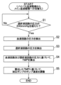
- the main control unit 22 monitors the pressure of the dialysate circuit 41 using the dialysate side pressure detection unit 72 (S1 ). Then, when the pressure in the dialysate circuit 41 exceeds 200 mmHg (S1: Yes), the pressure in the blood circuit 21 is detected by the blood side pressure detection section 35 (S2), and the pressure in the dialysate circuit 41 is detected by the dialysate side pressure detection section 72. Detect pressure (S3). After detecting the pressures in the blood circuit 21 and the dialysate circuit 41, the TMP in the dialyzer 10 is calculated based on both detected pressures (S4). Thereafter, based on the calculated TMP, the pump speed of the pressurizing pump 73 is adjusted so as to reduce the TMP (S5). This completes the water removal error reduction operation.
- S1 dialysate side pressure detection unit 72
- the pump speed of the pressure pump 73 among the plurality of pumps 63, 73, 74 arranged in the dialysate circuit 41 is adjusted, so The water removal error can be reduced without changing the control of the liquid supply pump 63 and the liquid drainage pump 74, which are driven in conjunction to control the amount of water removed.
- the pressure difference (TMP) between the blood circuit 21 and the dialysate circuit 41 is acquired, and the pump speed of the pressurizing pump 73 is adjusted using a correction value based on the pressure difference.
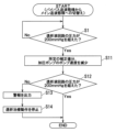
- the pump speed of the pressurizing pump 73 may be adjusted using a predetermined correction value. It's okay. For example, as shown in FIG.
- a step (S11) of reducing the pump speed of the pressurizing pump 73 by 10 minutes is performed.
- S12 it is determined whether the pressure in the dialysate circuit 41 exceeds 200 mmHg (S12), and if it is determined that the pressure in the dialysate circuit 41 does not exceed 200 mmHg ( If S12: No), an alarm is output (S13) and the dialysis treatment operation is stopped (S14).
- the pump speed of the pressurizing pump 73 is adjusted in the water removal error reduction operation, but the configuration may be such that the command value of the fluid pump disposed in the dialysate circuit 41 is adjusted.
- the command value of either the liquid supply pump 63 or the liquid drainage pump 74 may be adjusted.
- a configuration may be adopted in which the command values of a plurality of liquid feeding pumps are adjusted.
- the TMP in the dialyzer 10 is used as the pressure difference between the blood circuit 21 and the dialysate circuit 41 in the water removal error reduction operation, but the present invention is not limited to this.
- a configuration using the difference between the pressure of the blood circuit 21 and the pressure of the dialysate circuit 41 may be used.
- the pressure in the blood circuit 21 may be detected by the blood-side pressure detection section 35
- the pressure in the dialysate circuit 41 may be detected by the dialysate-side pressure detection section 72.
- the pressure detection of the blood circuit 21 and the dialysate circuit 41 and the adjustment of the command value of the pressurizing pump 73 based on the pressure detection are performed by switching the liquid feeding mode from the bypass liquid feeding mode to the main liquid feeding mode.
- the pressure detection of the blood circuit 21 and the dialysate circuit 41 and the adjustment of the command value of the pressurizing pump 73 based on this are changed from the bypass liquid feeding mode to the main feeding mode.
- the configuration may be such that it is performed before switching the liquid feeding mode when switching the liquid feeding mode to the liquid mode.
- the present invention is applied to the blood purification device 1 that controls the flow rate of the fluid supply and drainage in the dialyzer 10 using the separate fluid supply pump 63 and drainage pump 74.
- the present invention may be applied to a blood purification device that controls the flow rate of fluid supply and drainage in the dialyzer 10 by using a dual pump that integrates the fluid pump 63 and the drainage pump 74.
- a fluid pump is arranged separately from the duplex pump, and when a pressure difference occurs between the blood circuit 21 and the dialysing fluid circuit 41 in the water removal error reduction operation, the pressure difference is The command value of the liquid feeding pump is adjusted so as to reduce the size.
- the pressure of the dialysate circuit 41 is adjusted by adjusting the drive of the pressurizing pump 73 disposed in the dialysate circuit 41.
- a configuration may be adopted in which the pressure of the blood circuit 21 is adjusted.
- This blood purification device 101 is a medical device that performs dialysis treatment to purify the blood of patient C using a dialyzer 110, and is a so-called hemodialysis device.
- the present blood purification device 101 employs pump control that can reduce water removal errors when switching from the bypass liquid feeding mode to the main liquid feeding mode.
- the blood purification device 101 includes a dialyzer 110 that purifies the blood of a patient C, an extracorporeal circulation unit 111 that circulates the blood of the patient C via the dialyzer 110, and a dialyzer 110 that is connected to the dialyzer 110.
- the dialyzer 110 includes a dialysate supply and discharge unit 112 that supplies dialysate to the dialyzer 110 and discharges the dialysate from the dialyzer 110.
- the extracorporeal circulation unit 111 and the dialysate supply/drainage unit 112 are configured separately, and the dialyzer 110 is detachably attached to the extracorporeal circulation unit 111 via a fixing jig 113.
- the dialyzer 110 includes a blood purification membrane (a hollow fiber type hemodialysis membrane, a hemodiafiltration membrane, a flat membrane type hemodialysis membrane, or a hemofiltration membrane). Further, the dialyzer 110 has a blood inlet 110a for introducing blood, a blood outlet 110b for drawing out the introduced blood, a dialysate inlet 110c for introducing dialysate, and a dialysate drain for discharging the introduced dialysate. It has an outlet 110d. In dialyzer 110, blood is purified by bringing blood into contact with dialysate through a blood purification membrane.
- a blood purification membrane a hollow fiber type hemodialysis membrane, a hemodiafiltration membrane, a flat membrane type hemodialysis membrane, or a hemofiltration membrane.
- Dialyzer 110 water removal from patient C's blood is made possible by controlling the flow rate of fluid supplied to the dialyzer 110 and the flow rate of fluid drained from the dialyzer 110.
- Dialyzer 110 is an example of a blood purifier.
- the extracorporeal circulation unit 111 includes a blood circuit 121 that circulates the blood of the patient C via the dialyzer 110, a storage section 122, and a main control section 123.
- the storage unit 122 and main control unit 123 will be described later.
- the blood circuit 121 is connected to the blood inlet 110 a of the dialyzer 110 , is connected to an artery side blood flow path 131 that guides blood collected from the blood vessel of the patient C to the dialyzer 110 , and is connected to the blood outlet 110 b of the dialyzer 110 , and is connected to the blood outlet 110 b of the dialyzer 110 .
- the venous blood flow path 132 returns blood discharged from the blood vessel to the blood vessel of the patient C.
- a blood pump 134 for circulating blood is disposed in the arterial blood flow path 131.
- the venous blood flow path 132 is provided with a blood side pressure detection section 135 that detects the pressure of the venous blood flow path 132 .
- the blood side pressure detection section 135 is an example of a pressure detection means that detects the pressure of the blood circuit 121, and detects the pressure of the blood circuit 121 by detecting the pressure of the venous blood flow path 132.
- blood from the patient C is guided to the dialyzer 110 via the arterial blood flow path 131, and after the blood is purified by the dialyzer 110, it is transferred to the venous blood flow path. 132 to patient C. This purifies patient C's blood.
- the dialysate supply and discharge unit 112 includes a dialysate circuit 141 that supplies dialysate to the dialyzer 110 and discharges the dialysate from the dialyzer 110, and a sub-control unit 142.
- the dialysate circuit 141 is connected to a dialysate preparation section 151 that purifies the dialysate and to the dialysate inlet 110c of the dialyzer 110, and is a dialyzer that supplies the dialysate purified by the dialysate preparation section 151 to the dialyzer 110.
- the dialysate is sent in either a bypass liquid feeding mode or a bypass liquid feeding mode in which the dialysate is sent from the dialysate supply channel 152 to the dialysate discharge channel 153 via the dialysate supply channel 154.
- the main liquid feeding mode is an example of the first liquid feeding mode
- the bypass liquid feeding mode is an example of the second liquid feeding mode.
- the dialysate preparation unit 151 prepares a dialysate from the supplied pure water and a dialysate made of concentrated liquid or powder.
- the pure water supplied to the dialysate preparation unit 151 may be supplied from a pure water production unit installed in the dialysate supply and discharge unit 112, or may be provided outside the dialysate supply and discharge unit 112. Alternatively, the water may be supplied from a pure water production apparatus.
- the dialysate preparation section 151 can also be omitted, and, for example, the dialysate may be configured to be supplied to the dialysate supply/discharge unit 112 from an external dialysate supply device or the like.
- a fluid supply pump 163, a fluid supply side flowmeter 164, and a first electromagnetic valve 166 are arranged in the dialysate supply channel 152 from the upstream side.
- the liquid feed pump 163 is a liquid feed pump (a positive displacement diaphragm pump) that feeds the dialysate in the dialysate supply channel 152 . By driving the fluid supply pump 163, dialysate is supplied to the dialyzer 110.
- the liquid supply side flow meter 164 is a flow meter that is disposed downstream of the liquid supply pump 163 and detects the flow rate of the dialysate supply channel 152 (that is, the flow rate of the liquid supplied to the dialyzer 110).
- the first solenoid valve 166 is disposed downstream of the connection position to which the bypass channel 154 is connected, and switches the liquid feeding mode (flow path) between the main liquid feeding mode and the bypass liquid feeding mode. This is one of the solenoid valves for
- a second electromagnetic valve 171, a dialysate side pressure detection unit 172, a pressurizing pump 173, a drain pump 174, and a drain flow meter 175 are arranged in the dialysate discharge flow path 153 from the upstream side.
- the pressurizing pump 173 is an example of a liquid feeding pump and an auxiliary pump.
- the second solenoid valve 171 is disposed upstream of the connection position to which the bypass channel 154 is connected, and switches the liquid feeding mode (flow path) between the main liquid feeding mode and the bypass liquid feeding mode. This is one of the solenoid valves for
- the dialysate side pressure detection unit 172 detects the pressure of the dialysate discharge channel 153.
- the dialysate-side pressure detection unit 172 is an example of a pressure detection unit that detects the pressure of the dialysate circuit 141, and detects the pressure of the dialysate circuit 141 by detecting the pressure of the dialysate discharge channel 153.
- the drain pump 174 is a liquid pump (a positive displacement diaphragm pump) that feeds the dialysate from the dialysate discharge channel 153.
- the pressurizing pump 173 is a cascade pump (non-displacement pump) that pumps the dialysate in the dialysate discharge channel 153 to assist the drainage pump 174 in feeding the dialysate.
- the amount of water removed from patient C's blood is controlled by controlling the fluid supply pump 163 and the drainage pump 174 to adjust the flow rate of fluid supply and drainage fluid to the dialyzer 110.
- This blood purification apparatus 101 is capable of controlling the amount of water removed to perform dialysis treatment without water removal and dialysis treatment with water removal.
- the drain side flow meter 175 is a flow meter that is disposed downstream of the drain pump 174 and detects the flow rate of the dialysate discharge channel 153 (that is, the flow rate of the dialysate from the dialyzer 110).
- bypass flow path 154 One end of the bypass flow path 154 is connected between the fluid supply side flow meter 164 and the first electromagnetic valve 166 in the dialysate supply flow path 152, and the other end is connected between the dialysate side pressure detection unit 172 and the pressurizing pump 173. is connected between. Thereby, the bypass flow path 154 bypasses the dialyzer 110 without going through the dialyzer 110, and connects the dialysate supply flow path 152 and the dialysate discharge flow path 153. Further, a third electromagnetic valve 155 is arranged in the bypass passage 154 .
- the third solenoid valve 155 is a solenoid valve for switching the liquid feeding mode between the main liquid feeding mode and the bypass liquid feeding mode. That is, the first electromagnetic valve 166, the second electromagnetic valve 171, and the third electromagnetic valve 155 are examples of flow path switching means that switches the liquid feeding mode between the main liquid feeding mode and the bypass liquid feeding mode.
- the first solenoid valve 166 and the second solenoid valve 171 By closing the first solenoid valve 166 and the second solenoid valve 171 while opening the third solenoid valve 155, the liquid feeding mode is switched from the main liquid feeding mode to the bypass liquid feeding mode.
- the third solenoid valve 155 and opening the first solenoid valve 166 and the second solenoid valve 171 the liquid feeding mode is switched from the bypass liquid feeding mode to the main liquid feeding mode.
- the sub-control unit 142 communicates with the main control unit 123 of the extracorporeal circulation unit 111, and according to instructions from the main control unit 123, the liquid supply pump 163, drainage pump 174, pressure pump 173, and each electromagnetic valve 155, 166, 171.
- the sub-control unit 142 is realized by appropriately combining an arithmetic element such as a CPU, memory, software, an interface, a communication unit, and the like.
- the storage unit 122 is composed of a memory such as a flash ROM, and stores various data. In particular, as shown in FIG. 5, the storage unit 122 stores a switching operation database 181.
- the switching operation database 181 stores the pressure of the blood circuit 121, the pressure of the dialysate circuit 141, and the pump in the past liquid feeding mode switching operation, regarding the liquid feeding mode switching operation that switches the liquid feeding mode from the bypass liquid feeding mode to the main liquid feeding mode.
- This is a database that stores speed adjustment coefficients and water removal amount errors (hereinafter referred to as water removal errors). That is, regarding past liquid feeding mode switching operations, the pressure of the blood circuit 121, the pressure of the dialysate circuit 141, the pump speed adjustment coefficient, and the water removal error for each liquid feeding mode switching operation are stored.
- the pump speed adjustment coefficient is an example of a drive adjustment amount that adjusts the pump speed of the pressurizing pump 173 during the liquid feeding mode switching operation, and is a numerical value that represents the drive adjustment amount as a multiplier with respect to the original pump speed.
- this blood purification device 101 has a configuration that reduces water removal errors by adjusting the pump speed of the pressure pump 173 when switching the liquid feeding mode from the bypass liquid feeding mode to the main liquid feeding mode. have.
- the pump speed adjustment coefficient is a coefficient that indicates an increase or decrease in pump speed adjustment for reducing water removal errors. Further, this information stored in the switching operation database 181 is used to calculate (predict) an optimal pump speed adjustment coefficient in the liquid feeding mode switching operation.
- the main control unit 123 is realized by appropriately combining arithmetic elements such as a CPU, memory, software, interface, communication unit, etc., and receives the detected value of the blood side pressure detection unit 135 and drives the blood pump 134. control.
- the main control unit 123 also communicates with the sub-control unit 142 and receives the detected values of the flowmeters 164 and 175 and the dialysate-side pressure detection unit 172 via the sub-control unit 142. , the pressurizing pump 173, and the drain pump 174 are controlled.
- the main control section 123 communicates with the sub-control section 142 and controls the opening and closing of each electromagnetic valve 155 , 166 , 171 via the sub-control section 142 .
- the main control section 123 is an example of a drive control section.
- the main control section 123 mounted on the extracorporeal circulation unit 111 is the main controller, and the control sections 123 and 142 mounted on the extracorporeal circulation unit 111 and the dialysate supply/drainage unit 112 are in a master-slave relationship.
- the sub-control unit 142 mounted on the supply/discharge unit 112 is configured to follow commands from the main control unit 123, but as a master-slave relationship between the control units 123 and 142, the sub-control unit 142 mounted on the dialysate supply/discharge unit 112 is configured to follow instructions from the main control unit 123.
- the main control section 123 mounted on the extracorporeal circulation unit 111 may be configured to follow commands from the sub-control section 142, or the control sections 123 and 142 may have no master-slave relationship.
- the main control unit 123 controls the blood pump 134, the liquid supply pump 163, the pressure pump 173, and the Dialysis treatment is performed by driving the drainage pump 174. That is, during dialysis treatment, the blood pump 134 is driven to circulate blood through the dialyzer 110, the fluid supply pump 163 is driven to supply dialysate to the dialyzer 110, and the pressurizing pump 173 and drainage are The fluid pump 174 is activated to drain dialysate from the dialyzer 110.
- the fluid supply pump 163, pressurizing pump 173, and drainage pump 174 are controlled to control the flow rate of the fluid supplied to the dialyzer 110 (supply of dialysate) and the flow rate of fluid discharged from the dialyzer 110 (dialysate
- the amount of water removed from patient C's blood is controlled by adjusting the flow rate of water (discharge).
- the pressurizing pump 173 is driven at a set pump speed (rotational speed), and the liquid supply pump 163 is driven to achieve the target flow rate by feedback control based on the detected value of the liquid supply side flow meter 164.
- the drain pump 174 is driven to the target flow rate by feedback control based on the detected value of the drain side flow meter 175.
- the pump speed is an example of a command value for the liquid pump.
- the main control unit 123 switches the liquid feeding mode from the main liquid feeding mode to the bypass liquid feeding mode by controlling the opening and closing of each electromagnetic valve 155, 166, and 171 during preparation before dialysis treatment and when temporarily stopping dialysis treatment.
- the fluid supply pump 163, pressurizing pump 173, and drainage pump 174 are driven to cause the dialysate to flow within the dialysate circuit 141.
- This operation is called dialysate flow operation.
- the pressurizing pump 173 is driven at the set pump speed, and the fluid supply pump 163 is controlled to the target flow rate by feedback control based on the detected value of the fluid supply side flow meter 164.
- the drain pump 174 is driven to a target flow rate by feedback control based on the detected value of the drain side flowmeter 175.
- the liquid feeding mode is switched from the bypass liquid feeding mode to the main liquid feeding mode with each pump 163, 173, 174 of the dialysate circuit 141 being driven.
- a sudden pressure fluctuation occurs in the dialysate circuit 141 due to the difference between the pressure in the blood circuit 121 and the pressure in the dialysate circuit 141.
- This rapid pressure fluctuation affects the flow rate adjustment of the dialysate supply flow path 152 and the dialysate discharge flow path 153, resulting in an error in the amount of water removed from patient C's blood, as shown in FIG. 6A.
- the main control unit 123 performs control to reduce water removal errors due to pressure fluctuations when switching the liquid feeding mode from the bypass liquid feeding mode to the main liquid feeding mode in the liquid feeding mode switching operation.
- the main control unit 123 includes a reception unit 191, a model generation unit 192, an adjustment amount prediction unit 193, a drive adjustment unit 194, a liquid transfer mode switching operation, and a reception unit 191, a model generation unit 192, an adjustment amount prediction unit 193, a drive adjustment unit 194, It functions as a mode switching section 195 and a data recording section 196.
- the reception unit 191 receives the detection value of the blood side pressure detection unit 135 and the pressure of the blood circuit 121, and also receives the detection value of the dialysate side pressure detection unit 172 and receives the pressure of the dialysate circuit 141.
- the pressure of the blood circuit 121 and the pressure of the dialysate circuit 141 are received before switching the liquid feeding mode from the bypass liquid feeding mode to the main liquid feeding mode. For example, the pressure in the blood circuit 121 and the dialysate circuit 141 when an instruction to start dialysis treatment is given is accepted.
- the model generation unit 192 performs machine learning using the pressure of the blood circuit 121, the pressure of the dialysate circuit 141, the pump speed adjustment coefficient, and the water removal error of the past liquid feeding mode switching operation stored in the switching operation database 181 as training data. , generates a prediction model M (see FIG. 7) that takes the pressure of the blood circuit 121 and the pressure of the dialysate circuit 141 as input and outputs a pump speed adjustment coefficient that suppresses water removal errors.
- the water removal error in the fluid feeding mode switching operation is caused by the flow rate fluctuation due to the pressure difference between the pressure in the blood circuit 121 and the dialysate circuit 141.
- the prediction model M is based on, for example, data on past liquid feeding mode switching operations (pressure in the blood circuit 121, pressure in the dialysate circuit 141, pump speed adjustment coefficient, and water removal error) extracted from the switching operation database 181. Then, the relational expression between the pump speed adjustment coefficient and the water removal error in the input blood circuit 121 pressure and dialysate circuit 141 pressure is predicted, and the water removal error is suppressed based on the relational expression.
- the pump speed adjustment coefficient calculates the pump speed adjustment coefficient and output it. For example, when the pressure in the blood circuit 121 is higher than the pressure in the dialysate circuit 141, excessive water removal occurs. If the pressure of the dialysate circuit 141 is higher than the pressure of the blood circuit 121, the speed adjustment coefficient is predicted, and water is being replenished, so the pump speed is increased (more than 1) as a pump speed adjustment that suppresses the water removal error. Predict the coefficient. Note that it is preferable that the prediction model M predicts a pump speed adjustment coefficient at which the water removal error is 50 ml/h or less (preferably 0).
- the pressure in the blood circuit 121 and the dialysate circuit 141 at the time when an instruction to start dialysis treatment is given is used as the pressure in the blood circuit 121 and the pressure in the dialysate circuit 141, which are input data and teacher data.
- a configuration that uses the pressure of the blood circuit 121 and the dialysate circuit 141 several seconds after the instruction to start dialysis treatment is given may be used.
- the detected value of the blood side pressure detection section 135 and the detected value of the dialysate side pressure detection section 172 are used as the pressure of the blood circuit 121 and the pressure of the dialysate circuit 141, which are input data and teacher data.
- the present invention may be configured to use detected values or predicted values of other detection means.
- the data of the past liquid feeding mode switching operation be subjected to machine learning using only data from a certain period of time (for example, one year) as training data.
- Machine learning is a technology in which a computer learns large amounts of data and automatically constructs algorithms and models that perform tasks such as classification and prediction. Can be used.
- the prediction model M is generated assuming that the pump speed before adjustment of the pressurizing pump 173 in the liquid feeding mode switching operation is constant. That is, the prediction model M is generated by taking into account the certain numerical value of the pump speed before adjustment.
- the adjustment amount prediction unit 193 uses the prediction model M generated by the model generation unit 192 to predict a pump speed adjustment coefficient that suppresses water removal errors from the pressure of the blood circuit 121 and the pressure of the dialysate circuit 141. That is, the adjustment amount prediction unit 193 inputs the pressure of the blood circuit 121 and the pressure of the dialysate circuit 141 received by the reception unit 191 into the prediction model M, and acquires the pump speed adjustment coefficient output from the prediction model M.
- the drive adjustment unit 194 causes the adjustment amount prediction unit 193 to predict The drive of the pressurizing pump 173 is adjusted based on the pump speed adjustment coefficient. That is, the pump speed of the pressure pump 173 is multiplied by the predicted pump speed adjustment coefficient, and the set value of the pump speed of the pressure pump 173 is changed to the multiplied value, thereby increasing or decreasing the pump speed of the pressure pump 173.
- the pump speed of the pressure pump 173 is multiplied by the predicted pump speed adjustment coefficient, and the set value of the pump speed of the pressure pump 173 is changed to the multiplied value, thereby increasing or decreasing the pump speed of the pressure pump 173.
- the prediction model M sets a value (a value less than 1) to reduce the pump speed.
- the pump speed adjustment coefficient is predicted to suppress the water removal error, and the set value of the pump speed of the pressurizing pump 173 is lowered (the pressure of the dialysate circuit 141 is increased) based on the predicted pump speed adjustment coefficient.
- the prediction model M will set a value (over 1) for increasing the pump speed to a pump that suppresses water removal errors. Based on the predicted speed adjustment coefficient, the set value of the pump speed of the pressurizing pump 173 is increased (the pressure of the dialysate circuit 141 is lowered).
- the liquid feeding mode switching unit 195 switches the liquid feeding mode from the bypass liquid feeding mode to the main liquid feeding mode by controlling the opening and closing of each electromagnetic valve 155, 166, and 171. That is, the liquid feeding mode switching section 195 controls each of the solenoid valves 155, 166, and 171, and closes the third solenoid valve 155 while opening the first solenoid valve 166 and the second solenoid valve 171, thereby allowing bypass.
- the liquid feeding mode is switched from the liquid feeding mode to the main liquid feeding mode.
- the data recording unit 196 records data on the fluid feeding mode switching operation (pressure of the blood circuit 121, pressure of the dialysate circuit 141, pump speed adjustment coefficient, water removal error) in the switching operation database 181. That is, the detection value of each flow meter 164, 175 is received, the flow rate of the liquid supplied to the dialyzer 110 and the flow rate of the drained liquid from the dialyzer 110 are obtained, and the water removal error is calculated based on these. Then, the pressure of the blood circuit 121 and the pressure of the dialysate circuit 141 received by the reception unit 191, the pump speed adjustment coefficient predicted by the adjustment amount prediction unit 193, the calculated water removal error, and the execution of the liquid feeding mode switching operation.
- the date and time are recorded in the switching operation database 181 in association with each other.
- the water removal error is calculated based on the cumulative flow rate up to a predetermined second (for example, 45 seconds) after switching the liquid feeding mode to the main liquid feeding mode, and Record the water removal error value.
- the pressure of the blood circuit 121 and the pressure of the dialysate circuit 141 are accepted (S101) (acceptance step). That is, it receives the detection value of the blood side pressure detection section 135 and receives the pressure of the blood circuit 121, and also receives the detection value of the dialysate side pressure detection section 172 and receives the pressure of the dialysate circuit 141.
- the model generation unit 192 After receiving the pressures of the blood circuit 121 and the dialysate circuit 141, the model generation unit 192 generates a prediction model M (S102) (model generation step). That is, data on past liquid feeding mode switching operations (pressure in the blood circuit 121, pressure in the dialysate circuit 141, pump speed adjustment coefficient, and water removal error) is extracted from the switching operation database 181, and the extracted past liquid feeding mode is extracted. A predictive model M is generated by performing machine learning using the data of the switching operation as training data.
- the adjustment amount prediction unit 193 uses the prediction model M to predict a pump speed adjustment coefficient that suppresses the water removal error from the pressure of the blood circuit 121 and the dialysate circuit 141 (S103). adjustment amount prediction process). That is, the pressures of the blood circuit 121 and the dialysate circuit 141 received in S101 are input into the prediction model M generated by the model generation unit 192, and the pump speed adjustment coefficient output from the prediction model M is predicted. Get it as a value.
- the drive adjustment unit 194 adjusts the drive of the pressure pump 173 according to the predicted pump speed adjustment coefficient (S104) (drive adjustment step). That is, the pump speed of the pressure pump 173 is multiplied by the predicted pump speed adjustment coefficient, and the set value of the pump speed of the pressure pump 173 is changed to the multiplied value, thereby increasing or decreasing the pump speed of the pressure pump 173.
- the liquid feeding mode switching unit 195 controls each electromagnetic valve 155, 166, and 171 to switch the liquid feeding mode from the bypass liquid feeding mode to the main liquid feeding mode (S105).
- the adjustment amount prediction step (S103) and the drive adjustment step (S104) are performed only when there is a certain pressure difference between the blood circuit 121 and the dialysate circuit 141. That is, if there is no constant pressure difference between the blood circuit 121 and the dialysate circuit 141, it is preferable to omit the adjustment amount prediction step (S103) and the drive adjustment step (S104).
- the water removal error is calculated from the detected values of each flowmeter 164 and 175, and the pressure of the blood circuit 121 and the dialysate circuit 141 received in S101, the pump speed adjustment coefficient predicted in S103, and the calculated division are calculated.
- the water error and the implementation date of the liquid feeding mode switching operation are associated and recorded in the switching operation database 181. Note that if S103 is omitted, the pump speed adjustment coefficient is set to 1. This completes the main liquid feeding mode switching operation.
- the prediction model M is generated after starting the liquid feeding mode switching operation, but a configuration in which the prediction model M is generated in advance before starting the liquid feeding mode switching operation is also possible. It may be.
- the configuration may be such that, at the end of the liquid feeding mode switching operation, a prediction model M to be used for the next liquid feeding mode switching operation is generated. Further, a configuration may be adopted in which a common prediction model M is used in multiple liquid feeding mode switching operations.
- the pump speed adjustment coefficient that suppresses the water removal error is predicted based on the prediction model M generated from the data of past liquid feeding mode switching operations, and the bypass liquid feeding mode is
- the drive of the pressurizing pump 173 is adjusted using the pump speed adjustment coefficient, thereby switching the liquid feeding mode from the bypass liquid feeding mode to the main liquid feeding mode. It is possible to reduce water removal errors due to pressure fluctuations during the process.
- the optimal A pump speed adjustment factor can be used.
- the predictive model M is configured to machine learn only data on past liquid feeding mode switching operations over a certain period of time (for example, the past year), pipes, pumps, sensors, etc. It is possible to predict the pump speed adjustment coefficient taking into account the deterioration over time. Thereby, it is possible to accurately predict the pump speed adjustment coefficient that suppresses water removal errors.
- the pump speed of the pressurizing pump 173 among the plurality of pumps 163, 173, and 174 arranged in the dialysing fluid circuit 141 is adjusted, so the difference between the fluid supply and drainage is The water removal error can be reduced without changing the control of the liquid supply pump 163 and the liquid drainage pump 174, which are driven in conjunction to control the amount of water removed.
- the water removal amount control of the liquid supply pump 163 and the liquid drainage pump 174 and the control related to reducing the water removal error of the pressurizing pump 173 can be easily performed in parallel. 163 and the drainage pump 174, which would adversely affect water removal amount control.
- the prediction model M outputs the pump speed adjustment coefficient
- the adjustment amount prediction unit 193 uses the prediction model M to predict the pump speed adjustment coefficient. It is not limited to. For example, it may be configured to output and predict an adjusted pump speed obtained by multiplying the original pump speed by a pump speed adjustment coefficient, or it may be configured to output and predict an adjustment value to be subtracted or added to the original pump speed. It may be.
- the pressure in the blood circuit 121 and the pressure in the dialysate circuit 141 are used as the input data and the teacher data, but instead of this, the pressure in the blood circuit 121 and the pressure in the dialysate circuit are used as the input data and the teacher data.
- 141 (for example, a subtraction value or a division value between the pressure of the blood circuit 121 and the pressure of the dialysate circuit 141) may be used as input data and teacher data.
- the data of the liquid feeding mode switching operation of the blood purification device 101 itself is used as the training data of the prediction model M, but the liquid feeding mode switching operation of the blood purification device 101 itself is When the number of times that the switching operation is performed is small, sample data that complements this may be stored in the switching operation database 181.
- the data of the liquid feeding mode switching operation of the blood purification device 101 itself is used as the training data of the prediction model M, but the liquid feeding mode performed by another blood purification device 101 is
- the configuration may be such that the data of the mode switching operation is used as the training data of the prediction model M.
- the pump speed of the pressurizing pump 173 is adjusted based on the pump speed adjustment coefficient before switching the liquid feeding mode to the main liquid feeding mode.
- the pump speed of the pressure pump 173 may be adjusted based on the pump speed adjustment coefficient after the liquid feeding mode is switched to the main liquid feeding mode.
- the pump speed of the pressurizing pump 173 is adjusted in the liquid feeding mode switching operation, but the command value of the liquid feeding pump disposed in the dialysing fluid circuit 141 is adjusted.
- the configuration is not limited to this, as long as it is configured to do so.
- the command value of either the liquid supply pump 163 or the drainage pump 174 may be adjusted.
- a configuration may be adopted in which the command values of a plurality of liquid feeding pumps are adjusted.
- the pressure of the dialysate circuit 141 is adjusted by adjusting the driving of the liquid pump disposed in the dialysate circuit 141 in order to reduce the water removal error.
- a configuration may be adopted in which the pressure of the blood circuit 121 is adjusted by adjusting the drive of a liquid pump (for example, the blood pump 134) disposed in the blood circuit 121.
- a liquid pump for example, the blood pump 134
- the present invention is applied to the blood purification device 101 that controls the flow rates of fluid supply and drainage in the dialyzer 110 using separate fluid supply pumps 163 and drainage pumps 174.
- the present invention may be applied to a blood purification device that controls the flow rate of fluid supply and drainage in the dialyzer 110 using a dual pump that is integrally formed with the fluid supply pump 163 and the drainage pump 174.
- a blood circuit (21) that circulates the blood through a blood purifier (10) that purifies the blood of the patient (C), and a dialysate that supplies dialysate to the blood purifier (10).
- the control unit (22) controls the blood circuit (21) when the flow path switching means (55, 66, 76) switches the liquid feeding mode from the second liquid feeding mode to the first liquid feeding mode. and the dialysate circuit (41), the blood purification device (1) adjusts the driving of the liquid pump (73) so as to reduce the pressure difference. This makes it possible to reduce water removal errors due to pressure fluctuations when switching the liquid feeding mode from the bypass liquid feeding mode to the main liquid feeding mode.
- an auxiliary pump (73) as a liquid feeding pump; When switching the liquid feeding mode to the liquid mode, when the pressure difference occurs between the blood circuit (21) and the dialysate circuit (41), the auxiliary pump (73) is configured to reduce the pressure difference.
- the blood purification device (1) according to ⁇ 1>> which adjusts the drive of the blood purification device (1). Thereby, water removal errors can be reduced without changing the control of the liquid supply pump and the liquid drainage pump that are driven in conjunction with each other. Thereby, by changing the control, it is possible to prevent defects in the cooperation between the liquid supply pump and the liquid drainage pump.
- the drive control unit (22) acquires the pressure difference and causes the flow path switching means (55, 66, 76) to transfer the liquid from the second liquid feeding mode to the first liquid feeding mode.
- the drive control section (22) obtains the transmembrane pressure difference in the blood purifier (10) as the pressure difference
- the flow path switching means (55, 66, 76) obtains the transmembrane pressure difference in the blood purifier (10) as the pressure difference.
- ⁇ 1>> or ⁇ 3>> wherein when switching the liquid feeding mode from the liquid mode to the first liquid feeding mode, the driving of the liquid feeding pump (73) is adjusted based on the transmembrane pressure difference.
- the blood purification device (1) according to any one of the above. Thereby, the water removal error can be reduced with higher accuracy.
- the drive control unit (22) controls the flow path switching means (55, 66, 76) to switch the liquid feeding mode from the second liquid feeding mode to the first liquid feeding mode.
- Blood purification device (1) according to.
- the pressure in the dialysate circuit which has a correlation with the pressure difference, is used as a trigger to adjust the drive of the fluid pump, making it possible to omit the acquisition of blood circuit pressure.
- the water error reduction operation can be performed more easily.
- the drive control unit (22) controls the flow path switching means (55, 66, 76) to switch the liquid feeding mode from the second liquid feeding mode to the first liquid feeding mode.
- the blood purification device (1) according to any one of ⁇ 1>> to ⁇ 5>>, wherein the drive of the liquid feeding pump (73) is adjusted so as to reduce the pressure difference. Thereby, pressure fluctuation itself can be reduced when the liquid feeding mode is switched from the bypass liquid feeding mode to the main liquid feeding mode.
- a blood circuit (121) that circulates the blood through a blood purifier (110) that purifies the blood of the patient (C), and a dialysate that supplies dialysate to the blood purifier (110).
- the flow path switching means (155, 166, 176) for switching the liquid mode, the liquid feeding pump (173) and the flow path switching means (155, 166, 176) are controlled, and the liquid feeding mode is changed from the second liquid feeding mode to the liquid feeding mode.
- a drive control unit (122) that performs a liquid feeding mode switching operation to switch the liquid feeding mode to a first liquid feeding mode, and the drive control unit (122) controls the pressure of the blood circuit (121) and the dialysis mode.
- a reception unit (191) that receives the pressure of the liquid circuit (141) and an error in the pressure of the blood circuit (121), the pressure of the dialysate circuit (141), and the amount of water removed in the past switching operation of the liquid feeding mode are used.
- the liquid sending pump (173) uses a prediction model (M) subjected to machine learning as data to suppress an error in the amount of water removed from the pressure of the blood circuit (121) and the pressure of the dialysate circuit (141).
- an adjustment amount prediction unit (193) that predicts the drive adjustment amount of the adjustment amount predicted by the adjustment amount prediction unit (193) when switching the liquid feeding mode from the second liquid feeding mode to the first liquid feeding mode.
- a blood purification device (101) comprising: a drive adjustment section (194) that adjusts the drive of the liquid feeding pump (173) according to the drive adjustment amount. This makes it possible to reduce errors in the amount of water removed due to pressure fluctuations when switching the liquid feeding mode from the bypass liquid feeding mode to the main liquid feeding mode.
- the prediction model (M) includes errors in the pressure of the blood circuit (121), the pressure of the dialysate circuit (141), and the amount of water removed in the past switching operation of the liquid feeding mode, as well as errors in the past
- an auxiliary pump (173) as a liquid feeding pump, and the drive adjustment section (194) adjusts the adjustment amount when switching the liquid feeding mode from the second liquid feeding mode to the first liquid feeding mode.
- the blood purification device (101) according to ⁇ 7>> or ⁇ 8>>, wherein the drive of the auxiliary pump (173) is adjusted according to the drive adjustment amount predicted by the prediction unit (193).
- water removal errors can be reduced without changing the control of the liquid supply pump and the liquid drainage pump that are driven in conjunction with each other.
- a blood circuit (21) that circulates the blood through a blood purifier (10) that purifies the blood of the patient (C), and a dialysate that supplies dialysate to the blood purifier (10).
- a first feeding channel that includes a bypass channel (54) communicating with the blood purifier (10) and sends fluid from the dialysate supply channel (52) to the dialysate discharge channel (53). The liquid is sent from the dialysate supply flow path (52) to the dialysate discharge flow path (53) without passing through the blood purifier (10) and via the bypass flow path (54).
- the blood purification device (1) includes a flow path switching means (55, 66, 76) for switching the flow path switching means (55, 66, 76).
- the blood circuit (21) and the dialysate circuit ( 41) A control method for a liquid feeding pump (73), which adjusts a command value for the liquid feeding pump (73) so as to reduce the pressure difference when a pressure difference occurs between the liquid feeding pump (73) and the liquid feeding pump (73). This makes it possible to reduce water removal errors due to pressure fluctuations when switching the liquid feeding mode from the bypass liquid feeding mode to the main liquid feeding mode.
- a blood circuit (121) that circulates the blood through a blood purifier (110) that purifies the blood of the patient (C), and a dialysate that supplies dialysate to the blood purifier (110).
- a first liquid feeding mode including a bypass flow path (154) and sending the liquid from the dialysate supply flow path (152) to the dialysate discharge flow path (153) via the blood purifier (110); , a second liquid is sent from the dialysate supply flow path (152) to the dialysate discharge flow path (153) without passing through the blood purifier (110) and via the bypass flow path (154).
- a dialysate circuit (141) to which a liquid is fed in either of the two liquid feeding modes;
- a liquid feeding mode switching operation for switching a liquid feeding mode from the second liquid feeding mode to the first liquid feeding mode in a blood purification apparatus (101) comprising a path switching means (155, 166, 176).
- the liquid feeding mode switching step includes a receiving step (S101) of accepting the pressure of the blood circuit (121) and the pressure of the dialysate circuit (141), and a step of accepting the pressure of the blood circuit (121) and the dialysate circuit (141), and
- the blood circuit (121) is machine-learned using a prediction model (M) in which errors in the pressure of the blood circuit (121), the pressure of the dialysate circuit (141), and the amount of water removed in the mode switching operation are used as teacher data.
- a drive adjustment step (S104) of adjusting the command value of the liquid feeding pump according to the drive adjustment amount predicted in the adjustment amount prediction step (S103). and a method for controlling the liquid pump. This makes it possible to reduce water removal errors due to pressure fluctuations when switching the liquid feeding mode from the bypass liquid feeding mode to the main liquid feeding mode.
Landscapes
- Health & Medical Sciences (AREA)
- Heart & Thoracic Surgery (AREA)
- Vascular Medicine (AREA)
- Urology & Nephrology (AREA)
- Hematology (AREA)
- Engineering & Computer Science (AREA)
- Anesthesiology (AREA)
- Biomedical Technology (AREA)
- Life Sciences & Earth Sciences (AREA)
- Animal Behavior & Ethology (AREA)
- General Health & Medical Sciences (AREA)
- Public Health (AREA)
- Veterinary Medicine (AREA)
- Emergency Medicine (AREA)
- Cardiology (AREA)
- External Artificial Organs (AREA)
Priority Applications (3)
| Application Number | Priority Date | Filing Date | Title |
|---|---|---|---|
| CN202380050237.8A CN119677552A (zh) | 2022-06-28 | 2023-06-28 | 血液净化装置及送液泵的控制方法 |
| JP2024506224A JP7531073B2 (ja) | 2022-06-28 | 2023-06-28 | 血液浄化装置及び送液ポンプの制御方法 |
| EP23831506.3A EP4516332A4 (en) | 2022-06-28 | 2023-06-28 | BLOOD PURIFICATION DEVICE AND METHOD FOR CONTROLLING A LIQUID SUPPLY PUMP |
Applications Claiming Priority (2)
| Application Number | Priority Date | Filing Date | Title |
|---|---|---|---|
| JP2022-103782 | 2022-06-28 | ||
| JP2022103782 | 2022-06-28 |
Publications (1)
| Publication Number | Publication Date |
|---|---|
| WO2024005066A1 true WO2024005066A1 (ja) | 2024-01-04 |
Family
ID=89382388
Family Applications (1)
| Application Number | Title | Priority Date | Filing Date |
|---|---|---|---|
| PCT/JP2023/023962 Ceased WO2024005066A1 (ja) | 2022-06-28 | 2023-06-28 | 血液浄化装置及び送液ポンプの制御方法 |
Country Status (4)
| Country | Link |
|---|---|
| EP (1) | EP4516332A4 (https=) |
| JP (1) | JP7531073B2 (https=) |
| CN (1) | CN119677552A (https=) |
| WO (1) | WO2024005066A1 (https=) |
Citations (5)
| Publication number | Priority date | Publication date | Assignee | Title |
|---|---|---|---|---|
| JPS63255069A (ja) * | 1987-04-10 | 1988-10-21 | 株式会社 ニツシヨ− | 人工腎臓透析装置 |
| JPH01238870A (ja) * | 1988-03-18 | 1989-09-25 | Meteku:Kk | 血液透析における除水量制御装置 |
| JPH03133459A (ja) * | 1989-10-19 | 1991-06-06 | Nikkiso Co Ltd | 透析装置の除水制御監視システム |
| JPH08504116A (ja) * | 1992-11-12 | 1996-05-07 | アルシン・メディカル・インコーポレーテッド | 腎臓透析法及び装置 |
| JP2010029376A (ja) | 2008-07-28 | 2010-02-12 | Nikkiso Co Ltd | 透析装置 |
Family Cites Families (2)
| Publication number | Priority date | Publication date | Assignee | Title |
|---|---|---|---|---|
| JP6305848B2 (ja) * | 2014-06-27 | 2018-04-04 | 日機装株式会社 | 血液浄化装置 |
| EP3560577A1 (en) * | 2018-04-25 | 2019-10-30 | Gambro Lundia AB | Apparatus and method for testing integrity of an ultrafilter membrane |
-
2023
- 2023-06-28 JP JP2024506224A patent/JP7531073B2/ja active Active
- 2023-06-28 WO PCT/JP2023/023962 patent/WO2024005066A1/ja not_active Ceased
- 2023-06-28 CN CN202380050237.8A patent/CN119677552A/zh active Pending
- 2023-06-28 EP EP23831506.3A patent/EP4516332A4/en active Pending
Patent Citations (5)
| Publication number | Priority date | Publication date | Assignee | Title |
|---|---|---|---|---|
| JPS63255069A (ja) * | 1987-04-10 | 1988-10-21 | 株式会社 ニツシヨ− | 人工腎臓透析装置 |
| JPH01238870A (ja) * | 1988-03-18 | 1989-09-25 | Meteku:Kk | 血液透析における除水量制御装置 |
| JPH03133459A (ja) * | 1989-10-19 | 1991-06-06 | Nikkiso Co Ltd | 透析装置の除水制御監視システム |
| JPH08504116A (ja) * | 1992-11-12 | 1996-05-07 | アルシン・メディカル・インコーポレーテッド | 腎臓透析法及び装置 |
| JP2010029376A (ja) | 2008-07-28 | 2010-02-12 | Nikkiso Co Ltd | 透析装置 |
Non-Patent Citations (1)
| Title |
|---|
| See also references of EP4516332A4 |
Also Published As
| Publication number | Publication date |
|---|---|
| CN119677552A (zh) | 2025-03-21 |
| JPWO2024005066A1 (https=) | 2024-01-04 |
| EP4516332A4 (en) | 2025-12-24 |
| JP7531073B2 (ja) | 2024-08-08 |
| EP4516332A1 (en) | 2025-03-05 |
Similar Documents
| Publication | Publication Date | Title |
|---|---|---|
| WO2015152236A1 (ja) | 血液浄化装置及び血液浄化装置の補液・プライミング方法 | |
| JP2004049493A (ja) | 血液透析装置および血液透析装置の制御プログラム | |
| JP7531073B2 (ja) | 血液浄化装置及び送液ポンプの制御方法 | |
| WO2024004481A1 (ja) | 血液浄化装置及び送液ポンプの制御方法 | |
| JP6566687B2 (ja) | 血液浄化装置、血液浄化装置のプライミング方法及び作動方法 | |
| JP7445827B1 (ja) | 血液浄化装置 | |
| US20250381330A1 (en) | Blood purification device, and method for determining detection defect in flow meter | |
| JP7363904B2 (ja) | 血液浄化装置 | |
| JP7484933B2 (ja) | 血液浄化装置 | |
| CN110831639A (zh) | 用于连续性肾脏替代疗法的过滤系统 | |
| WO2023090428A1 (ja) | 体腔液処理システム | |
| JP7789028B2 (ja) | 血液浄化装置及び血液浄化システム | |
| US12478717B2 (en) | Extracorporeal device and method for removal of secondary membrane | |
| JP4097811B2 (ja) | 血液透析用装置 | |
| JP7790230B2 (ja) | 血液浄化装置 | |
| JP2024075976A (ja) | 血液浄化装置 | |
| US20240350713A1 (en) | Systems for supplying medical fluid for renal replacement therapy and methods of operating such systems | |
| US20250269099A1 (en) | Method for Operating Blood Treatment System and Corresponding Blood Treatment System | |
| JPH05146506A (ja) | 血液透析装置 | |
| HK40101032A (zh) | 用於去除次级膜的体外装置和方法 | |
| WO2024150754A1 (ja) | 血液浄化装置 | |
| JP2024024651A (ja) | 血液浄化装置 | |
| CN114144211A (zh) | 具有三个平衡室的透析设备 |
Legal Events
| Date | Code | Title | Description |
|---|---|---|---|
| ENP | Entry into the national phase |
Ref document number: 2024506224 Country of ref document: JP Kind code of ref document: A |
|
| 121 | Ep: the epo has been informed by wipo that ep was designated in this application |
Ref document number: 23831506 Country of ref document: EP Kind code of ref document: A1 |
|
| WWE | Wipo information: entry into national phase |
Ref document number: 2023831506 Country of ref document: EP |
|
| ENP | Entry into the national phase |
Ref document number: 2023831506 Country of ref document: EP Effective date: 20241128 |
|
| WWE | Wipo information: entry into national phase |
Ref document number: 202380050237.8 Country of ref document: CN |
|
| NENP | Non-entry into the national phase |
Ref country code: DE |
|
| WWP | Wipo information: published in national office |
Ref document number: 202380050237.8 Country of ref document: CN |