WO2024004166A1 - 距離測定装置 - Google Patents
距離測定装置 Download PDFInfo
- Publication number
- WO2024004166A1 WO2024004166A1 PCT/JP2022/026365 JP2022026365W WO2024004166A1 WO 2024004166 A1 WO2024004166 A1 WO 2024004166A1 JP 2022026365 W JP2022026365 W JP 2022026365W WO 2024004166 A1 WO2024004166 A1 WO 2024004166A1
- Authority
- WO
- WIPO (PCT)
- Prior art keywords
- light
- scanning
- change
- distance
- light receiving
- Prior art date
- Legal status (The legal status is an assumption and is not a legal conclusion. Google has not performed a legal analysis and makes no representation as to the accuracy of the status listed.)
- Ceased
Links
Images




Classifications
-
- G—PHYSICS
- G01—MEASURING; TESTING
- G01B—MEASURING LENGTH, THICKNESS OR SIMILAR LINEAR DIMENSIONS; MEASURING ANGLES; MEASURING AREAS; MEASURING IRREGULARITIES OF SURFACES OR CONTOURS
- G01B11/00—Measuring arrangements characterised by the use of optical techniques
- G01B11/24—Measuring arrangements characterised by the use of optical techniques for measuring contours or curvatures
-
- G—PHYSICS
- G01—MEASURING; TESTING
- G01S—RADIO DIRECTION-FINDING; RADIO NAVIGATION; DETERMINING DISTANCE OR VELOCITY BY USE OF RADIO WAVES; LOCATING OR PRESENCE-DETECTING BY USE OF THE REFLECTION OR RERADIATION OF RADIO WAVES; ANALOGOUS ARRANGEMENTS USING OTHER WAVES
- G01S17/00—Systems using the reflection or reradiation of electromagnetic waves other than radio waves, e.g. lidar systems
- G01S17/02—Systems using the reflection of electromagnetic waves other than radio waves
- G01S17/06—Systems determining position data of a target
- G01S17/08—Systems determining position data of a target for measuring distance only
- G01S17/10—Systems determining position data of a target for measuring distance only using transmission of interrupted, pulse-modulated waves
-
- G—PHYSICS
- G01—MEASURING; TESTING
- G01S—RADIO DIRECTION-FINDING; RADIO NAVIGATION; DETERMINING DISTANCE OR VELOCITY BY USE OF RADIO WAVES; LOCATING OR PRESENCE-DETECTING BY USE OF THE REFLECTION OR RERADIATION OF RADIO WAVES; ANALOGOUS ARRANGEMENTS USING OTHER WAVES
- G01S17/00—Systems using the reflection or reradiation of electromagnetic waves other than radio waves, e.g. lidar systems
- G01S17/02—Systems using the reflection of electromagnetic waves other than radio waves
- G01S17/06—Systems determining position data of a target
- G01S17/42—Simultaneous measurement of distance and other co-ordinates
-
- G—PHYSICS
- G01—MEASURING; TESTING
- G01S—RADIO DIRECTION-FINDING; RADIO NAVIGATION; DETERMINING DISTANCE OR VELOCITY BY USE OF RADIO WAVES; LOCATING OR PRESENCE-DETECTING BY USE OF THE REFLECTION OR RERADIATION OF RADIO WAVES; ANALOGOUS ARRANGEMENTS USING OTHER WAVES
- G01S17/00—Systems using the reflection or reradiation of electromagnetic waves other than radio waves, e.g. lidar systems
- G01S17/88—Lidar systems specially adapted for specific applications
- G01S17/93—Lidar systems specially adapted for specific applications for anti-collision purposes
- G01S17/931—Lidar systems specially adapted for specific applications for anti-collision purposes of land vehicles
-
- G—PHYSICS
- G01—MEASURING; TESTING
- G01S—RADIO DIRECTION-FINDING; RADIO NAVIGATION; DETERMINING DISTANCE OR VELOCITY BY USE OF RADIO WAVES; LOCATING OR PRESENCE-DETECTING BY USE OF THE REFLECTION OR RERADIATION OF RADIO WAVES; ANALOGOUS ARRANGEMENTS USING OTHER WAVES
- G01S7/00—Details of systems according to groups G01S13/00, G01S15/00, G01S17/00
- G01S7/48—Details of systems according to groups G01S13/00, G01S15/00, G01S17/00 of systems according to group G01S17/00
- G01S7/481—Constructional features, e.g. arrangements of optical elements
- G01S7/4817—Constructional features, e.g. arrangements of optical elements relating to scanning
Definitions
- Embodiments of the present invention relate to a distance measuring device.
- Light projection methods such as the light cutting method, phase shift method, and spatial code method have been proposed as ranging methods based on triangulation using structured illumination.
- the light cutting method projects a band-shaped scanning light onto the object while scanning the object, images the object from an imaging position different from the projection position, and calculates the projection angle of the scanning light and the projected target.
- the distance to the object is calculated by triangulation based on the angle of incidence of reflected light from the object onto the imaging surface and the baseline length between the light projection position and the imaging position (see, for example, Patent Document 1) .
- the projection angle of the scanning light can be determined, for example, from the command value to the scanner or the detection time of the bright line of the reflected light appearing on the imaging surface, and the incident angle of the reflected light can be determined, for example, from the incident position of the reflected light on the imaging surface.
- the optical cutting method is said to have good accuracy, but compared to the phase shift method or spatial code method, the problem is that it takes more time to measure because it requires a larger number of images for one measurement. .
- a frame-based image sensor outputs a frame image at a predetermined cycle by opening and closing a shutter for a predetermined period of time for exposure, whereas an event-based image sensor monitors each pixel independently and asynchronously from time to time.
- an event for example, a change in brightness exceeding a predetermined value
- the position, time, and polarity for example, whether it became brighter or darker
- Event-based image sensors have a wider dynamic range than frame-based image sensors, and are characterized by high speed because they only output event information. Therefore, it is believed that the use of event-based image sensors can speed up the photosection method.
- a photoelectric switch or other means may be used to detect a specific mirror angle, but the photoelectric switch has a certain measurement error based on its specifications. Measurement errors may become a factor that deteriorates distance measurement accuracy.
- One aspect of the present disclosure includes a light projecting unit that irradiates a rotating or swinging mirror with light from a light source and projects the obtained scanning light onto a target object; a distance information calculation section that calculates a distance to the object based on a scanning angle of the scanning light obtained from time information of a change in brightness of the object due to the scanning light; a direction changing section that changes the direction of the scanning light so that the light receiving section can detect the reference light;
- This distance measuring device uses time information of a luminance change as a reference time, and uses time information of a luminance change of the object as a relative value from the reference time.
- FIG. 2 is a plan view of a stereo camera showing the measurement principle of the stereo method.
- FIG. 2 is a plan view of a light cutting system showing the measurement principle of the light cutting method.
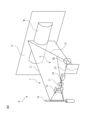
- 1 is a schematic perspective view of a three-dimensional measuring device using an optical cutting method.
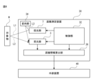
- FIG. 1 is a block diagram of a distance measuring device according to an embodiment.
- FIG. 1 is a schematic configuration diagram of a distance measuring device according to a first embodiment.
- FIG. 2 is a schematic configuration diagram of a distance measuring device according to a second embodiment.
- FIG. 2 is a schematic configuration diagram of a distance measuring device according to a third embodiment.
- FIG. 1 is a plan view of a stereo camera 1 showing the measurement principle of the stereo method.
- the stereo camera 1 includes, for example, a left light receiving section 2 and a right light receiving section 3, which correspond to two cameras.
- the left light-receiving section 2 and the right light-receiving section 3 are arranged, for example, in equidistant parallel arrangement.
- each light-receiving surface is, for example, an image sensor in which a plurality of pixels are arranged two-dimensionally, but may also be a line sensor or the like in which a plurality of pixels are arranged one-dimensionally (for example, arranged only in the x direction).
- the image of the point P on the right light receiving surface 5 corresponding to the image of the point P on the left light receiving surface 4 is detected by image processing such as pattern matching. If possible, it can be seen that the parallax D can be found from the pitch between pixels on both light-receiving surfaces, and the distance Z to the point P of the object can be found.
- the light cutting system is, for example, a stereo camera 1 in which the left light receiving section 2 is replaced with a light projecting section.
- FIG. 2 is a plan view of the optical cutting system 6 showing the measurement principle of the optical cutting method
- FIG. 3 is a schematic perspective view of the optical cutting system 6.
- the light cutting system 6 includes a light projecting unit 7 that corresponds to, for example, a projector.
- the light projector 7 projects, for example, a belt-shaped scanning light L1 onto an object W in the target space S while scanning it, and the light receiver 3 receives the reflected light L2 reflected from the object W.
- the light projection section 7 includes a light source 10 for the scanning light L1, projection optical systems 11 and 12 that shape the beam of the scanning light L1, and a scanning section 13 that scans the scanning light L1.
- the light source 10 is configured of, for example, a semiconductor laser, but is not limited to this.
- the light source 10 may include a solid laser (fiber laser, YAG laser, etc.), a gas laser (carbon dioxide laser, helium neon laser, argon laser, etc.), etc. It may also be composed of other light sources.
- the projection optical systems 11 and 12 are composed of beam shaping lenses such as collimating lenses and cylindrical lenses.
- the scanning unit 13 is configured with a scanner including, for example, a galvano scanner, an encoder, or a photoelectric sensor for detecting a specific scanning direction.
- the scanning light L1 is emitted from the light source 10, shaped into a slit light by the projection optical systems 11 and 12, scanned by the scanning section 13, and projected onto the object W.
- the light receiving unit 3 includes a light receiving optical system 20 that receives reflected light L2 from the object W, and an image sensor 21.
- the light receiving optical system 20 includes, for example, a condenser lens.
- the image sensor 21 has, for example, a plurality of pixels arranged in a two-dimensional array, but is not limited thereto.
- the image sensor 21 may be composed of a plurality of pixels arranged in a one-dimensional array.
- the reflected light L2 reflected by the object W is collected by the light receiving optical system 20, and is received by the image sensor 21, and a change in brightness is detected.
- the virtual left light receiving surface 4 of the light projection unit 7 The position of the pixel x l is obtained from the following equation 2.
- the light projecting unit 7 rotates and irradiates the scanning light from the light projection starting point around the Y axis perpendicular to the XZ plane at a constant angular velocity ⁇ , and the scanning light passes through the left optical axis at time t 0 and at time t.
- the projection angle ⁇ can be obtained from Equation 3 below.
- the above configuration and measurement principle are just examples, and the design can be changed as appropriate depending on the design of the system configuration, layout, etc.
- the light emitting section 7 and the right light receiving section 3 may be laid out without being equidistantly parallel, or instead of replacing the left light receiving section 2 with the light emitting section 7, the left light receiving section 2 and the right light receiving section
- a light projection section 7 may be prepared, and a system configuration combining the stereo method and the light cutting method may be adopted.
- a light projecting section 7 may be employed that projects a beam-like spot light or a block-check pattern light onto the object instead of the band-like slit light. It should be noted that the method for calculating three-dimensional information also changes in accordance with such design changes.
- FIG. 4 shows a block diagram of a three-dimensional distance measuring device 30 as an example.
- the distance measuring device 30 includes, for example, a computer device including a processor, a memory, an input/output unit, and the like.
- the processor includes, for example, a CPU (central processing unit), the memory includes, for example, RAM (random access memory), ROM (read only memory), etc., and the input/output unit inputs or outputs various data used or generated by the processor. .
- the memory stores, for example, programs executed by the processor and various data used or generated by the processor.
- the distance measuring device 30 includes a light projecting section 7 that projects scanning light L1 onto an object W while scanning it, a light receiving section 3 that receives reflected light L2 reflected by the object W at a plurality of pixels, and a light projecting section. 7 and a control section 32 that controls the operation of the light receiving section 3; a redirecting section 34 that deflects the light from the light projecting section 7 and makes it enter the light receiving section 3 without passing through the object W; and a light receiving section 3, and a distance information calculation unit 36 that calculates three-dimensional information of the target object W by triangulation based on the information output from 3 and the like.
- the light projecting section 7 corresponds to, for example, a projector
- the light receiving section 3 corresponds to, for example, a camera
- the control section 32 and distance information calculation section 36 correspond to, for example, a processor.
- the scanning light L1 various types of light such as slit light, spot light, pattern light, etc. can be used.
- the light projecting unit 7 may project a plurality of reference beams while maintaining a predetermined projection angle interval. Since the measurement time of the distance measuring device 30 is determined by the time required to scan the object W with the reference light, it is common to increase the scanning speed to shorten the measurement time. becomes a constraint. Therefore, by projecting a plurality of reference beams, it is possible to shorten the measurement time while maintaining an increased scanning speed under the restriction of the response speed of the light receiving section 3.
- the light receiving unit 3 includes, for example, an image sensor in which a plurality of pixels are arranged in a two-dimensional array, but it may also be a normal camera, a line sensor in which a plurality of pixels are arranged in a one-dimensional array, or a light sensor in which a plurality of pixels are arranged in a one-dimensional manner. It may be a single photodetector (such as a luminance meter) configured to detect.
- a preferred example of the light receiving section 3 is an event-based sensor.
- the light receiving section 3 is composed of a plurality of pixels, and when the change in brightness at each pixel is equal to or greater than a predetermined threshold, the light receiving section 3 detects the position of the pixel, The time at which the brightness change occurred and the polarity representing the direction of the brightness change are output as events.
- the light receiving unit 3 monitors each pixel independently and asynchronously from time to time, and when it detects an event exceeding a predetermined value (for example, a change in brightness exceeding a predetermined value), the light receiving unit 3 Event information such as location, time, polarity (for example, whether it became bright or dark) is output.
- the sensor of the light receiving section 3 may be a general frame-based sensor.
- the light receiving section 3 outputs a frame image at a predetermined period by opening and closing a shutter for a predetermined period of time to expose the sensor to light.
- the frame image includes, for example, a frame number, brightness information of each pixel, and the like.
- the pixel in which an event captures the reflected light from the target object, so the distance information calculation unit 36 receives information from the light receiving unit 3.
- Distance measurement is performed based on the output event information (for example, the position, time, and polarity of the pixel where the brightness has changed). Since the slit width of the scanning light and the spot diameter of the spot light may correspond to multiple pixel sizes, the intermediate time between the time when the pixel begins to brighten and the time when it finishes darkening is determined. Distance measurement may also be performed.
- the distance information calculation unit 36 calculates the position and frame number (corresponding to time) of the pixel that has the maximum brightness from the plurality of frame images output from the light receiving unit 3. is detected, and distance measurement is performed based on this detected information.
- the distance information calculated by the distance information calculation unit 36 may be output to an external device 40, such as a robot control device or a vehicle control device, provided outside the distance measuring device 30.
- the output distance information can be used by the external device 40, and for example, the external device 40 can perform position control, speed control, acceleration control, etc. based on the three-dimensional information that reduces the influence of the multiple reflected reference light. becomes possible.
- FIG. 5 is a schematic configuration diagram of the distance measuring device 30 according to the first embodiment.
- the distance measuring device 30 includes a housing 42 , and a light projecting section 7 and a light receiving section 3 arranged inside the case 42 , and the light projecting section 7 includes a light source 44 and a rotating mirror 46 .
- the rotating mirror may rotate in one direction at a predetermined angular velocity, or may swing at a predetermined angular velocity.
- the light from the light source 44 is reflected by the rotating mirror 46, and heads toward the measurement object W as scanning light L1 that passes within a predetermined scanning direction range (scan range) 52 for the object W, and is reflected by the object W to produce reflected light. It reaches the light receiving section 3 as L2.
- a photoelectric switch (not shown) is used to detect a specific angle of the rotating mirror 46.
- One possible method is to provide a By detecting a specific angle each time using a photoelectric switch and using the detection time as a reference, it is possible to suppress the effects of changes in rotational movement and swinging movement over time and fluctuations due to external disturbances such as vibration, and to adjust the projection angle ⁇ of scanning light L1. It becomes possible to find.
- the photoelectric switch has a certain detection error based on its specifications, etc., and this detection error can become a factor that deteriorates the distance measurement accuracy as the measurement time of the distance measurement device becomes faster.
- an interface circuit for transmitting and receiving the output of the photoelectric sensor is also required, which may increase the cost of the entire device.
- the distance measuring device 30 uses the scanning light in a specific scanning direction from the light source 44 as the reference light L3, and allows the light receiving unit 3 to detect the reference light 3 (part of it in many cases). It has a direction changing part 34 for this purpose.
- the angle of the rotating mirror 46 is such that the light from the light source 44 becomes the reference light L3 that forms an angle ⁇ P with the reference line 70 (corresponding to the left optical axis in FIG. 1 or 2).
- the direction changing section 34 changes the direction of the reference light L3 within the housing 42 so that the light receiving section 3 can detect (receive) the reference light L3.
- the deflection unit 34 includes a fixed mirror 48 and a reflector 50 arranged in a housing 42, and the reference light L3 reflected by the rotating mirror 46 is reflected by the fixed mirror 48 and reflected. The light heads toward the body 50 and is further reflected by the reflector 50 to reach the light receiving section 3.
- ⁇ P indicates an angle on the opposite side (negative side) of the scanning direction with respect to the reference line 70, but it should be noted that in such a case, ⁇ P is a negative number. .
- the scanning angle ⁇ can be calculated, and the distance to the object can be calculated.
- the reference time t P is required to be accurate.
- photoelectric switches have detection errors.
- the scanning unit 13 when configured using a motor equipped with a galvano scanner or an encoder, a signal indicating that a specific angle has been detected can be output from the motor control system, but generally these control systems are It operates with a dedicated control cycle, and a jitter error caused by this control cycle is superimposed on the output detection signal.
- the above-mentioned photoelectric switch and detection signals from the photoelectric switch and motor control system are not required. Furthermore, since the light receiving section that originally receives the reflected light L2 reflected by the object W is used as is, that is, times tP and t in Equation 3a are the times of brightness changes detected by the same light receiving section, so there is a large error. It becomes possible to identify the scan angle ⁇ with high precision with few factors. This also applies to the second and third embodiments described below.
- the reference light L3 is shown as light outside the scan range 52, but for more accurate distance measurement, the scanning direction of the reference light L3 should be in a direction adjacent to the scan range 52. It is preferable that there be. If they are adjacent, the reference time tP and the time t in the scanning direction ⁇ will be closer, and the influence of the above-mentioned changes in the rotational movement and swinging movement over time and fluctuations due to external disturbances such as vibrations will be reduced, resulting in further improvement. This is because high accuracy can be expected.
- the adjacent direction means a state that is close to the scan range 52 to the extent that there is no problem in measuring the distance as a distance measuring device and that the distance measuring device 30 and the direction changing unit 34 can be physically configured, for example.
- the minimum angle between the reference light L3 and the scan range 52 is within 15 degrees, preferably within 10 degrees, and more preferably within 5 degrees.
- the scanning direction of the reference light L3 can also be set within the scanning range 52.
- the scanning light moves from the right side to the left side of the field of view of the light receiving unit (camera) 3
- the pixels on the left side of the field of view are detected as a specific scanning direction at the timing when the scanning light starts to appear on the right side of the field of view. It is also possible.
- the reflector 50 is within the field of view (angle of view) 54 of the light receiving unit (for example, camera) 3, it is preferably placed outside the angle of view 56 of the distance measuring device. Further, the reflector 50 only needs to have an appropriate reflectance so that the light receiving section can be detected. For example, if the inner surface of the housing 42 has an appropriate reflectance, it can also serve as the reflector 50. Normally, a dark-colored nonwoven fabric with low reflectance is attached to the inner surface of the casing 42 to prevent diffused reflection, but by not attaching a nonwoven fabric or the like to the area corresponding to the reflector 50, it is possible to easily A reflector 50 can be formed.
- any mirror may be used as long as it can direct the reference light L3 toward the reflector 50.
- a mirror whose angle can be adjusted may be used, or a part of the inner surface of the casing 42 may be made mirror-like.
- the direction changing section 34 in the housing so that the light receiving section 3 can detect the reference light L3 in a specific scanning direction, the scanning when a change in the brightness of the object W is detected
- the angle ⁇ of light can now be determined with high precision, making it possible to perform high-precision distance measurement in an extremely short measurement time, for example by taking advantage of the high speed of event-based image sensors.
- FIG. 6 is a schematic configuration diagram of a distance measuring device 30 according to the second embodiment.
- parts that are different from the first embodiment will be mainly explained, and components that are the same or similar to those in the first embodiment will be given the same or similar reference numerals, and detailed explanations may be omitted. be.
- a half mirror 64 is provided in the housing 42 so that the light receiving unit 3 can receive (detect) both the reflected light L2 from the object W and the reference light L3 from the fixed mirror 46. .
- the angle of view 56 as a distance measuring device is limited, but a half mirror is used. Therefore, this limitation does not occur, and the angle of view 56 of the distance measuring device can be set to the same wide range as the field of view (angle of view) of the light receiving unit (for example, camera) 3.
- a plate-shaped object 68 having an opening (for example, a pinhole) 66 through which only the reference light L3 at the angle ⁇ P passes may be arranged between the fixed mirror 48 and the half mirror 64. This makes it possible to reduce the incidence of unnecessary light on the light receiving section 3, and further narrowing the angular range of the angle ⁇ P in which the light receiving section (for example, camera) 3 receives light, so that the light receiving section 3 receives the light at the angle ⁇ P. Accurate detection becomes possible (light close to the angle ⁇ P cannot be received).
- FIG. 7 is a schematic configuration diagram of a distance measuring device 30 according to a third embodiment.
- the third embodiment parts that are different from the first embodiment will be mainly explained, and components that are the same or similar to those in the first embodiment will be given the same or similar reference numerals, and detailed explanations may be omitted. be.
- the fixed mirror 48 is not used, and a light guide tube 60 having one end 61 through which the reference light L3 can enter is provided in the housing 42, and the light emitted from the other end 62 of the light guide tube 60 is is reflected by the same reflector 50 as in the first embodiment and detected by the light receiving section 3.
- the reflector 50 is not used, and the other end 62 of the light guide tube 60 is placed inside the camera field of view 54 and at the device field of view 56, so that the light emitted from the other end 62 is directly received by the light receiving section 3. You may also do so.
- slit light was used as the scanning light in the above embodiment, the present disclosure is not limited thereto.
- a method of scanning a point light source such as scanning the field of view of a camera using a galvanometer mirror, MEMS, etc. in a raster scan manner, is also applicable to this embodiment.
- a point light source can reduce the output of the light source compared to a slit light, while increasing the time to scan the field of view and requiring a scanning mechanism in two directions.
- first, second and third embodiments described above can also be combined as appropriate.
- the plate 68 with the opening 66 in the second embodiment may be applied to the first or third embodiment.
Landscapes
- Physics & Mathematics (AREA)
- Engineering & Computer Science (AREA)
- Electromagnetism (AREA)
- General Physics & Mathematics (AREA)
- Computer Networks & Wireless Communication (AREA)
- Radar, Positioning & Navigation (AREA)
- Remote Sensing (AREA)
- Measurement Of Optical Distance (AREA)
- Length Measuring Devices By Optical Means (AREA)
Abstract
Description




以下、特に変向部34の機能を中心に、距離測定装置30の実施例について説明する。図5は、第一実施例に係る距離測定装置30の概略構成図である。距離測定装置30は、筐体42と、筐体42内に配置された投光部7及び受光部3とを有し、投光部7は光源44及び回転ミラー46を含む。回転ミラーは、所定の角速度で一方向に回転するものでもよいし、所定の角速度で揺動するものでもよい。光源44からの光は回転ミラー46で反射され、対象物Wに対する所定の走査方向範囲(スキャン範囲)52内を通る走査光L1として測定対象物Wに向かい、対象物Wで反射されて反射光L2として受光部3に至る。ここで回転ミラーが所定の角速度で一方向に回転していること、又は所定の角速度で揺動していることを前提に、回転ミラー46の特定の角度を検出するための光電スイッチ(図示せず)を設ける手法が考えられる。光電スイッチにより特定の角度を毎回検出し、その検出時刻を基準にすることで、回転動作や揺動動作の経時変化や振動等の外乱による変動の影響を抑制し、走査光L1の投射角度θを求めることが可能になる。しかし光電スイッチにはその仕様等に基づく一定の検出誤差があり、この検出誤差が、距離測定装置の測定時間を高速化していくに従い、測距精度を悪化させる要因となり得る。また光電センサを使用する場合は、光電センサの出力を送受信等するためのインターフェース回路等も必要となり、装置全体としてコストアップの要因ともなり得る。
図6は、第二実施例に係る距離測定装置30の概略構成図である。第二実施例では、主に第一実施例と異なる部分について説明し、第一実施例と同一又は類似の構成要素には同一又は類似の参照符号を付与し、詳細な説明は省略する場合がある。
図7は、第三実施例に係る距離測定装置30の概略構成図である。第三実施例では、主に第一実施例と異なる部分について説明し、第一実施例と同一又は類似の構成要素には同一又は類似の参照符号を付与し、詳細な説明は省略する場合がある。
2 左受光部
3 右受光部
4 左受光面
5 右受光面
6 光切断システム
7 投光部
10 光源
11、12 投光光学系
13 走査部
20 受光光学系
21 イメージセンサ
30 距離測定装置
32 制御部
34 変向部
36 距離情報算出部
40 外部装置
42 筐体
44 光源
46 回転ミラー
48 固定ミラー
50 反射体
52 スキャン範囲
54 カメラ画角
56 装置画角
60 導光管
61、62 端部
64 ハーフミラー
66 開口
68 プレート
B 基線長
D 視差
f 焦点距離
P 対象物の点
W 対象物
Z 対象物の点Pまでの距離
θ 投射角度
Claims (4)
- 光源からの光を回転又は揺動するミラーに照射し、得られた走査光を対象物に投光する投光部と、
前記走査光による前記対象物の輝度変化を検出する受光部と、
前記走査光による前記対象物の輝度変化の時刻情報から求めた走査光の走査角に基づいて、前記対象物の距離を算出する距離情報算出部と、
特定の走査方向の基準光を前記受光部が検出できるように前記走査光を変向する変向部と、を備え、
前記距離情報算出部は、前記変向部が変向した基準光によって前記受光部に発生した輝度変化の時刻情報を基準時刻とし、前記対象物の輝度変化の時刻情報を前記基準時刻からの相対値とする、距離測定装置。 - 前記受光部は複数の画素で構成され、各画素における輝度変化が予め定めた閾値以上あった場合に、前記画素の位置、前記輝度変化があった時刻、及び輝度変化の方向を表す極性をイベントとして出力する、請求項1に記載の距離測定装置。
- 前記走査光はスリット光である、請求項1又は2に記載の距離測定装置。
- 前記特定の走査方向は、前記対象物への走査方向範囲に隣接する方向である、請求項1又は2に記載の距離測定装置。
Priority Applications (4)
| Application Number | Priority Date | Filing Date | Title |
|---|---|---|---|
| PCT/JP2022/026365 WO2024004166A1 (ja) | 2022-06-30 | 2022-06-30 | 距離測定装置 |
| JP2024530228A JP7817398B2 (ja) | 2022-06-30 | 2022-06-30 | 距離測定装置 |
| DE112022006794.2T DE112022006794T5 (de) | 2022-06-30 | 2022-06-30 | Gerät zur Abstandsmessung |
| CN202280097323.XA CN119487360A (zh) | 2022-06-30 | 2022-06-30 | 距离测定装置 |
Applications Claiming Priority (1)
| Application Number | Priority Date | Filing Date | Title |
|---|---|---|---|
| PCT/JP2022/026365 WO2024004166A1 (ja) | 2022-06-30 | 2022-06-30 | 距離測定装置 |
Publications (1)
| Publication Number | Publication Date |
|---|---|
| WO2024004166A1 true WO2024004166A1 (ja) | 2024-01-04 |
Family
ID=89382531
Family Applications (1)
| Application Number | Title | Priority Date | Filing Date |
|---|---|---|---|
| PCT/JP2022/026365 Ceased WO2024004166A1 (ja) | 2022-06-30 | 2022-06-30 | 距離測定装置 |
Country Status (4)
| Country | Link |
|---|---|
| JP (1) | JP7817398B2 (ja) |
| CN (1) | CN119487360A (ja) |
| DE (1) | DE112022006794T5 (ja) |
| WO (1) | WO2024004166A1 (ja) |
Cited By (1)
| Publication number | Priority date | Publication date | Assignee | Title |
|---|---|---|---|---|
| US20240146887A1 (en) * | 2022-10-31 | 2024-05-02 | Seiko Epson Corporation | Method of outputting pattern image, projector, and non-transitory computer-readable storage medium storing program |
Citations (3)
| Publication number | Priority date | Publication date | Assignee | Title |
|---|---|---|---|---|
| JPH10206132A (ja) * | 1996-11-19 | 1998-08-07 | Minolta Co Ltd | 3次元計測システム |
| JP2016033482A (ja) * | 2014-07-31 | 2016-03-10 | 船井電機株式会社 | レーザレンジファインダ |
| JP2021032763A (ja) * | 2019-08-27 | 2021-03-01 | ソニー株式会社 | 測距システム及び電子機器 |
Family Cites Families (4)
| Publication number | Priority date | Publication date | Assignee | Title |
|---|---|---|---|---|
| JP5932371B2 (ja) | 2012-02-02 | 2016-06-08 | 三菱電機株式会社 | 形状測定装置 |
| JP2014159988A (ja) | 2013-02-19 | 2014-09-04 | Yaskawa Electric Corp | 物体検出装置、ロボットシステム、及び物体検出方法 |
| DE102019128814B4 (de) | 2019-10-25 | 2021-05-20 | Sick Ag | Kamera zur Erfassung eines Objektstroms und Verfahren zur Bestimmung der Höhe von Objekten |
| JP7549025B2 (ja) | 2020-09-07 | 2024-09-10 | ファナック株式会社 | 三次元計測装置 |
-
2022
- 2022-06-30 DE DE112022006794.2T patent/DE112022006794T5/de active Pending
- 2022-06-30 JP JP2024530228A patent/JP7817398B2/ja active Active
- 2022-06-30 CN CN202280097323.XA patent/CN119487360A/zh active Pending
- 2022-06-30 WO PCT/JP2022/026365 patent/WO2024004166A1/ja not_active Ceased
Patent Citations (3)
| Publication number | Priority date | Publication date | Assignee | Title |
|---|---|---|---|---|
| JPH10206132A (ja) * | 1996-11-19 | 1998-08-07 | Minolta Co Ltd | 3次元計測システム |
| JP2016033482A (ja) * | 2014-07-31 | 2016-03-10 | 船井電機株式会社 | レーザレンジファインダ |
| JP2021032763A (ja) * | 2019-08-27 | 2021-03-01 | ソニー株式会社 | 測距システム及び電子機器 |
Cited By (1)
| Publication number | Priority date | Publication date | Assignee | Title |
|---|---|---|---|---|
| US20240146887A1 (en) * | 2022-10-31 | 2024-05-02 | Seiko Epson Corporation | Method of outputting pattern image, projector, and non-transitory computer-readable storage medium storing program |
Also Published As
| Publication number | Publication date |
|---|---|
| CN119487360A (zh) | 2025-02-18 |
| DE112022006794T5 (de) | 2025-02-13 |
| JPWO2024004166A1 (ja) | 2024-01-04 |
| JP7817398B2 (ja) | 2026-02-18 |
Similar Documents
| Publication | Publication Date | Title |
|---|---|---|
| JP5016245B2 (ja) | 物体の六つの自由度を求めるための測定システム | |
| US6862097B2 (en) | Three-dimensional shape measuring method, and three-dimensional shape measuring apparatus | |
| CN100464159C (zh) | 位置检测装置 | |
| EP3772633B1 (en) | Surveying instrument | |
| JPH0219708A (ja) | カメラの測距装置 | |
| JP2023126981A (ja) | 光学式変位計 | |
| JPH11257917A (ja) | 反射型光式センサ | |
| JPWO2014073262A1 (ja) | 撮像素子位置検出装置 | |
| US20150226543A1 (en) | Optical probe, attachable cover, and shape measuring apparatus | |
| WO2023089788A1 (ja) | 三次元計測装置 | |
| JP7817398B2 (ja) | 距離測定装置 | |
| JP2010085395A (ja) | 光学式位置角度検出装置 | |
| JPH10239036A (ja) | 3次元計測用光学装置 | |
| JPH05306915A (ja) | 形状測定方法およびその装置 | |
| JPH085344A (ja) | 3次元形状入力装置 | |
| JP3324367B2 (ja) | 3次元入力カメラ | |
| JPH06258042A (ja) | 距離測定方法および装置 | |
| JPH024843B2 (ja) | ||
| JP2002062220A (ja) | 走査光学系の検査方法及び検査装置 | |
| JP2000088539A (ja) | 3次元入力方法及び3次元入力装置 | |
| JPS62291512A (ja) | 距離測定装置 | |
| JP4611174B2 (ja) | 撮像素子位置測定装置及び撮像素子位置測定方法 | |
| JPS63138204A (ja) | 形状測定方法 | |
| JP2001227923A (ja) | 輪郭形状測定方法及び輪郭形状測定装置 | |
| JP2001317922A (ja) | 光学式形状測定装置 |
Legal Events
| Date | Code | Title | Description |
|---|---|---|---|
| 121 | Ep: the epo has been informed by wipo that ep was designated in this application |
Ref document number: 22949439 Country of ref document: EP Kind code of ref document: A1 |
|
| ENP | Entry into the national phase |
Ref document number: 2024530228 Country of ref document: JP Kind code of ref document: A |
|
| WWE | Wipo information: entry into national phase |
Ref document number: 112022006794 Country of ref document: DE |
|
| WWE | Wipo information: entry into national phase |
Ref document number: 18865337 Country of ref document: US |
|
| WWE | Wipo information: entry into national phase |
Ref document number: 202280097323.X Country of ref document: CN |
|
| WWP | Wipo information: published in national office |
Ref document number: 112022006794 Country of ref document: DE |
|
| WWP | Wipo information: published in national office |
Ref document number: 202280097323.X Country of ref document: CN |
|
| 122 | Ep: pct application non-entry in european phase |
Ref document number: 22949439 Country of ref document: EP Kind code of ref document: A1 |