WO2024004162A1 - 無人航空機 - Google Patents
無人航空機 Download PDFInfo
- Publication number
- WO2024004162A1 WO2024004162A1 PCT/JP2022/026352 JP2022026352W WO2024004162A1 WO 2024004162 A1 WO2024004162 A1 WO 2024004162A1 JP 2022026352 W JP2022026352 W JP 2022026352W WO 2024004162 A1 WO2024004162 A1 WO 2024004162A1
- Authority
- WO
- WIPO (PCT)
- Prior art keywords
- antenna
- aircraft
- unmanned aircraft
- flight
- pilot
- Prior art date
- Legal status (The legal status is an assumption and is not a legal conclusion. Google has not performed a legal analysis and makes no representation as to the accuracy of the status listed.)
- Ceased
Links
Images


Classifications
-
- B—PERFORMING OPERATIONS; TRANSPORTING
- B64—AIRCRAFT; AVIATION; COSMONAUTICS
- B64C—AEROPLANES; HELICOPTERS
- B64C39/00—Aircraft not otherwise provided for
- B64C39/02—Aircraft not otherwise provided for characterised by special use
Definitions
- the present invention relates to an unmanned aircraft, and more particularly, to an unmanned aircraft that directs the antenna of the unmanned aircraft toward a pilot aircraft.
- omnidirectional antennas such as monopoles and dipoles have been used as communication antennas mounted on unmanned aircraft such as drones and multicopters.
- An omnidirectional antenna has a null point in the direction of the tip of the antenna and in the opposite direction. Therefore, when at least one of the unmanned aircraft and the pilot aircraft is located in the direction of the null point of the other antenna, communication between the unmanned aircraft and the pilot aircraft may become unstable or communication may be interrupted. was there.
- the present invention was made to solve the above problems, and one of the objects is to provide an unmanned aircraft that can ensure stability of communication with a pilot aircraft.
- One aspect of the present invention is an unmanned aerial vehicle, comprising: an antenna for communicating with a pilot aircraft that controls the unmanned aerial vehicle; and an acquisition unit that acquires the position of the unmanned aerial vehicle; an acquisition unit that acquires the position and/or the position of the pilot aircraft, a storage unit that stores the flight start position, the current position of the unmanned aircraft acquired by the acquisition unit, and the flight start position or of the pilot aircraft. a direction determining unit that determines a direction from the current position to the flight start position or the position of the pilot aircraft based on the position; and an antenna control device that controls the direction of the antenna, the direction determining unit and an antenna control device that changes the direction of the antenna in the direction determined by.
- FIG. 1 is an external view of a multicopter that is an example of an unmanned aircraft (multicopter) according to an embodiment.
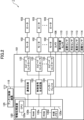
- 1 is a diagram showing the overall configuration of an unmanned aircraft according to an embodiment.
- FIG. 1 is a configuration diagram related to antenna control of an unmanned aircraft according to an embodiment. 1 is an example of an operation flowchart related to antenna control of an unmanned aircraft according to an embodiment.
- FIG. 3 is an external view of a multicopter that is an example of an unmanned aerial vehicle (multicopter) according to a modification of the embodiment.
- FIG. 2 is a configuration diagram of an adaptive array antenna.
- the unmanned aircraft of the present invention is not limited to the multicopter shown in FIG. 1, but may be any other unmanned aircraft such as a rotary wing aircraft or a fixed wing aircraft.
- the configuration of the unmanned aircraft 1 is not limited to that shown in the drawings, but can be any configuration as long as it can perform similar operations.
- an operation performed by multiple components may be performed by a single component, such as integrating the function of a communication circuit into the flight control unit, or the functions of a control device may be distributed among multiple control devices, etc.
- Operations performed by a single component may be performed by multiple components.
- the various data stored in the memory of the unmanned aircraft 1 may be stored in a different location, and the information recorded in the various memories may be distributed from one type of information to multiple types. Alternatively, multiple types of information may be stored together as one type.
- FIG. 1 is an external view of a multicopter that is an example of an unmanned aircraft (multicopter) 1 according to the present embodiment.
- FIG. 2 is a diagram showing the overall configuration of the unmanned aircraft 1.
- the unmanned aircraft 1 includes a control device 101, a motor 102, a rotor 103, an arm 104, a landing gear 105, a camera 106, a flight position sensor 110, an attitude sensor 111, a direction sensor 112, and an altitude sensor. 113, a distance sensor 114, and an antenna 115.
- the control device 101 is configured to perform information processing to control the flight of the unmanned aircraft 1 and control electrical signals for that purpose, and typically has various electronic components arranged and wired on a board. This is a device that has the circuits necessary to realize such functions. Details of the control device 101 will be described later.
- the motor 102 is driven by a control signal from the control device 101.
- the rotor (rotor blade) 103 is rotated by the drive of each motor 102 and generates lift.
- Arm 104 connects control device 101 and each motor 102 .
- the landing legs 105 support the unmanned aircraft 1 during landing.
- the number of motors 102, rotors 103, and arms 104 is six in the example shown in FIG. 1, but they can also be three or more, such as three or four, respectively.
- the camera 106 is a camera for capturing an image of a target object with high resolution.
- the camera 106 is rotatably provided in the control device 101, so that the imaging direction can be changed.
- the camera 106 acquires image data of the photographing range of the unmanned aircraft 1 while it is in flight, and the acquired images are stored in a storage unit to be described later.
- the image is typically a moving image consisting of a series of still images.
- the flight position sensor 110 is a sensor that senses the position of the unmanned aircraft 1, and is typically a GPS (Global Positioning System) sensor. Flight position sensor 110 preferably senses three-dimensional coordinates (latitude, longitude, altitude). In this embodiment, the flight position sensor 110 senses the horizontal position (latitude, longitude) of the unmanned aircraft 1.
- GPS Global Positioning System
- the attitude sensor 111 is a sensor for detecting the movement and inclination of the unmanned aircraft 1, and is, for example, a 6-axis gyro sensor (acceleration/angular velocity sensor).
- the attitude sensor 111 can be used to control the attitude of the unmanned aircraft 1 during flight.
- the direction sensor 112 is a sensor for controlling the flight direction, and is, for example, a magnetic sensor.
- the altitude sensor 113 is a sensor that detects the altitude of the unmanned aircraft 1, and is, for example, an atmospheric pressure sensor (barometer). The altitude sensor 113 can be used to control the flight altitude of the unmanned aircraft 1.
- the distance sensor 114 is a sensor that measures the distance between obstacles and the ground, avoids collisions with obstacles, and precisely measures altitude above the ground.
- Distance sensor 114 is, for example, an ultrasonic sensor.
- the antenna 115 is an antenna for receiving radio signals including information and various data for operating and controlling the unmanned aircraft 1, and for transmitting radio signals including image signals, video signals, and telemetry signals from the unmanned aircraft 1. It is. Antenna 115 can be used to communicate with a pilot aircraft that pilots unmanned aircraft 1 . Although the antenna 115 is provided at the upper part of the unmanned aircraft 1 in FIG. 1, it may be provided at the lower part of the unmanned aircraft 1, or may be provided at any arbitrary location.
- the unmanned aircraft 1 includes a power supply system including a battery device such as a lithium polymer battery or a lithium ion battery, and a power distribution system to each element.
- a battery device such as a lithium polymer battery or a lithium ion battery
- a power distribution system to each element.
- the control device 101 includes an information processing device 120, a communication circuit 121, a control signal generation circuit 122, a speed controller 123, an interface 124, and an antenna control device 125.
- the communication circuit 121 demodulates a control signal, a control signal, various data, etc. for the unmanned aircraft 1 from the radio signal received through the antenna 115 and inputs the demodulated data to the information processing device 120 or inputs the image output from the unmanned aircraft 1.
- a controller propo or pilot aircraft
- the information processing device 120 includes a CPU 120a, a RAM 120b, a ROM 120c, an external memory 120d, and a system bus 120e.
- RAM 120b, ROM 120c, external memory 120d, communication circuit 121, control signal generation circuit 122, and interface 124 are connected to CPU 120a via system bus 120e.
- the information processing device 120 appropriately controls the flight of the unmanned aircraft 1 based on control signals from the operator (during non-autonomous flight), flight plan route data (during autonomous flight), and the like. Specifically, the attitude, speed, etc. of the unmanned aircraft 1 are determined based on information obtained from various sensors 111 and 112 for flight control, and the unmanned aircraft 1 is determined based on information obtained from the flight position sensor 110, altitude sensor 113, and distance sensor 114.
- the information processing device 120 calculates the control command value for each rotor 103 by determining the current flight position of the rotor 103 and comparing it with target values such as the control signal, flight plan route, speed limit, altitude limit, etc. Data indicating the value is output to the control signal generation circuit 122.
- the control signal generation circuit 122 is configured to convert control command value data obtained by calculation by the information processing device 120 into a pulse signal (PWM signal, etc.) representing voltage, and typically includes an oscillation circuit and a switching circuit. It is an IC that includes.
- the control signal generation circuit 122 converts the control command value into a pulse signal representing voltage and transmits it to each speed controller 123.
- the speed controller 123 is configured to convert the pulse signal from the control signal generation circuit 122 into a drive voltage for driving the motor 102, and is typically a smoothing circuit and an analog amplifier. Each speed controller 123 converts the pulse signal into a drive voltage and applies it to each motor 102, thereby controlling the drive of each motor 102 and controlling the rotation speed of each rotor 103, thereby controlling the speed of the unmanned aircraft 1. Flight is controlled.
- the interface 124 converts the format of the signal so that it can be transmitted and received between functional elements such as the information processing device 120, flight position sensor 110, attitude sensor 111, direction sensor 112, altitude sensor 113, and distance sensor 114. This configuration electrically connects them. Note that for convenience of explanation, the interface is shown as one configuration in the drawings, but different interfaces are usually used depending on the type of functional element to be connected. Further, the interface 124 may not be necessary depending on the type of signal input/output by the functional element to be connected. Further, in FIG. 2, even if the information processing apparatus 120 is connected without an interface 124, an interface may be necessary depending on the type of signal input/output by the functional element to be connected.
- the antenna control device 125 changes the direction of the antenna 115.
- the antenna control device 125 is a turntable 125a provided with the antenna 115, and the turntable 125a is provided in the control device 101 as shown in FIG.
- the rotary table 125a is provided on the upper part of the unmanned aircraft 1 (control device 101), but the installation location is not particularly limited as long as it is provided on the unmanned aircraft 1.
- the rotating table 125a may be provided at the bottom of the unmanned aircraft 1.
- the antenna 115 is located at the bottom of the unmanned aircraft 1.
- the rotary table 125a is configured to be rotatable around an axis J in the vertical direction.
- the rotary table 125a includes, for example, a motor, a motor shaft that is provided on the motor and rotates around an axis J in the vertical direction when driven by the motor, and a table fixed to the motor shaft to which the antenna 115 is attached. and has.
- a drive voltage is applied to the motor based on a control command value for the amount of rotation of the motor calculated by the control device 101 (for example, the information processing device 120 or the direction determining unit 150 described below), so that the rotary table 125a is rotated. Rotate to change the orientation of the antenna 115.
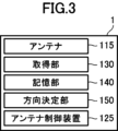
- FIG. 3 is a configuration diagram related to antenna control of the unmanned aircraft 1.
- the unmanned aircraft 1 includes an antenna 115, an acquisition section 130, a storage section 140, a direction determination section 150, and an antenna control device 125.
- the antenna 115 can be used to communicate with a pilot aircraft that controls the unmanned aircraft 1, and can be, for example, an omnidirectional antenna, a directional antenna, or a directional dual-polarization patch antenna (microstrip antenna). .
- the directional dual polarization patch antenna is, for example, a 180 degree directional dual polarization patch antenna.
- the antenna 115 is provided at the upper part of the unmanned aircraft 1 in FIG. 1, it may be provided at the lower part of the unmanned aircraft 1, or may be provided at any location on the unmanned aircraft 1.
- the acquisition unit 130 acquires the position of the unmanned aircraft 1.
- the acquisition unit 130 is, for example, the flight position sensor 110 and the altitude sensor 113.
- the position of the unmanned aircraft 1 can include the flight start position when the unmanned aircraft 1 starts its flight, and any position during the flight of the unmanned aircraft 1.
- the flight start position is the position of the unmanned aircraft 1 at or immediately before the flight start.
- the position of the unmanned aircraft 1 includes the horizontal position (latitude, longitude) of the unmanned aircraft 1 acquired by the flight position sensor 110 and the altitude of the unmanned aerial vehicle 1 acquired by the altitude sensor 113.
- Altitude is the height based on sea level or average sea level, and height is the length in the vertical direction.
- the acquisition unit 130 may acquire the position of the pilot aircraft that pilots the unmanned aircraft 1. Further, the position information of the unmanned aircraft 1 and/or the pilot aircraft acquired by the acquisition unit 130 may be information acquired from outside. For example, the acquisition unit 130 may acquire the flight start position of the unmanned aircraft 1 and/or the position of the pilot aircraft from the outside via an input device such as a keyboard, mouse, or touch panel.
- the storage unit 140 stores the flight start position acquired by the acquisition unit 130.
- the storage unit 140 can be, for example, a memory or storage included in the information processing device 120, such as a RAM 120b, a ROM 120c, or an external memory 120d.
- the direction determination unit 150 determines the direction from the current position of the unmanned aircraft 1 to the flight start position by calculation, based on the current position of the unmanned aircraft 1 and the flight start position acquired by the acquisition unit 130.
- the direction determining unit 150 can take into consideration the attitude of the unmanned aircraft 1 at the time when the current position is acquired by the acquiring unit 130 during this calculation.
- the direction determining unit 150 can obtain the attitude of the unmanned aircraft 1 using the attitude sensor 111.
- the direction determining unit 150 can be configured by the information processing device 120, for example.
- the calculation of the direction from the current position of the unmanned aircraft 1 to the flight start position by the direction determination unit 150 may be performed all the time, or may be performed at predetermined time intervals.
- the setting of this time interval can be set or changed as appropriate.
- This time interval is a time interval that allows the antenna 115 to track the position of the pilot aircraft (the flight start position of the unmanned aircraft 1), and may be, for example, several seconds, but is not limited thereto.
- the direction determination unit 150 of the present embodiment calculates a rotation amount command value to the motor of the rotating platform 125a in order to direct the antenna 115 from the determined current position of the unmanned aircraft 1 to the flight start position, It is output to the antenna control device 125.
- the calculation of the rotation amount command value may be performed by the information processing device 120 and output to the antenna control device 125.
- the antenna control device 125 changes the direction of the antenna 115 from the current position to the flight start position determined by the direction determining unit 150. That is, the antenna control device 125 (rotary table 125a) rotates the antenna 115 so that the antenna 115 is oriented toward the flight start position.
- the antenna control device 125 has a control circuit, and the control circuit includes an IC including an oscillation circuit and a switching circuit, a smoothing circuit, and an analog amplifier, similar to the control signal generation circuit 122 and the speed controller 123.
- the antenna control device 125 applies a drive voltage to the motor of the rotary table 125 a to rotate the motor based on the rotation amount command value for the motor of the rotary table 125 a obtained from the direction determining unit 150 , and changes the direction of the antenna 115 . Change the direction to face the flight start position. Note that "the direction of the antenna 115 is directed toward the flight start position" means that the direction in which the antenna 115 has the highest sensitivity is directed toward the flight start position or the pilot aircraft, and the direction in which the antenna 115 has the highest sensitivity is directed toward the flight start position or It is preferable to point it at the pilot aircraft.
- FIG. 4 is an example of an operation flowchart related to antenna control of the unmanned aircraft 1.
- the unmanned aircraft 1 and the pilot aircraft for controlling it are located within a relatively short distance (for example, several tens of centimeters to several meters), and communication between the two is stable. It shall be possible to carry out the
- the unmanned aircraft 1 acquires a flight start position using the flight position sensor 110 and the altitude sensor 113 (S01: acquisition of flight start position).
- the acquired flight start position is stored in the storage unit 140 (S02: storage of flight start position).
- the unmanned aircraft 1 receives a control signal from the pilot aircraft via the antenna 115 (S03: reception of the control signal), and rotates the rotor 103 by driving the motor 102 based on the control signal. , fly (S04: flight of unmanned aircraft).
- the unmanned aircraft 1 obtains the current position of the unmanned aircraft 1 using the flight position sensor 110 and the altitude sensor 113 (S05: Obtaining the current position of the unmanned aircraft).
- the direction determination unit 150 calculates the direction from the current position to the flight start position based on the acquired current position and the flight start position stored in the storage unit 140, and determines the direction (S06: (Determination of direction from current position to flight start position).
- the direction determining unit 150 calculates the amount of rotation of the rotary table 125a to the motor as a command value so that the antenna 115 is directed from the current position of the unmanned aircraft 1 to the flight start position, and The value is output to the antenna control device 125 (turntable 125a).
- the antenna control device 125 changes the direction of the antenna 115 from the current position of the unmanned aircraft 1 to the flight start position determined by the direction determining unit 150 (S07: from the current position of the unmanned aircraft 1 to the flight start position). change of antenna orientation).
- the antenna control device 125 applies a drive voltage to the motor of the rotary table 125a to rotate the motor based on the rotation amount command value to the motor of the rotary table 125a obtained from the direction determining unit 150, and the antenna Change the direction of 115 to face the flight start position.
- the unmanned aerial vehicle 1 of this embodiment includes an antenna 115 for communicating with a pilot aircraft that controls the unmanned aerial vehicle 1, and an acquisition unit 130 that acquires the position of the unmanned aerial vehicle 1.
- An acquisition unit 130 that acquires the position
- a storage unit 140 that stores the flight start position
- a flight start position of the unmanned aircraft 1 based on the current position of the unmanned aircraft 1 acquired by the acquisition unit 130 and the flight start position.
- a direction determining unit 150 that determines the direction of the starting position by calculation
- an antenna control device 125 that controls the direction of the antenna 115, which determines the direction of the flight starting position from the current position of the unmanned aircraft 1 determined by the direction determining unit 150.
- An antenna control device 125 that changes the direction of the antenna 115 in the direction shown in FIG.
- the unmanned aircraft 1 can ensure the stability of communication with the pilot aircraft. Since the antenna 115 can be oriented toward the flight start position, it is possible to prevent communication breakdown and video transmission interruption when the antennas of the unmanned aircraft 1 and the pilot aircraft are oriented toward their null points. In conventional unmanned aircraft, when the direction of the null point of the antenna of the unmanned aircraft matches the direction of the null point of the antenna of the pilot aircraft, communication between the two is possible, taking into account the communication breakdown that would occur over long distances. Whereas it was necessary to limit the distance, in this embodiment, the directivity of the antenna 115 can be directed toward the flight start position, so there is no need to limit the distance as described above.
- the antenna 115 is directed toward the flight start position because the position of the pilot aircraft that controls the unmanned aircraft 1 and the flight start position are relatively close and are equivalent positions for communication. This is because it can be considered.
- the antenna control device 125 is a rotary table 125a on which the antenna 115 is installed. Thereby, even if the position of the unmanned aircraft 1 changes due to flight, the antenna 115 can be directed toward the pilot aircraft.
- the antenna 115 was a directional dual-polarization patch antenna. Thereby, communication stability can be ensured compared to the case where an omnidirectional antenna or a directional antenna is used as the antenna 115.
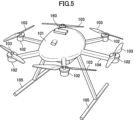
- the unmanned aircraft 1 may include an adaptive array antenna 160, as shown in FIG.
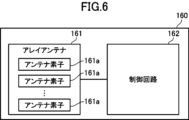
- the adaptive array antenna 160 includes an array antenna 161 formed by arranging a plurality of antenna elements 161a, and a control circuit 162 that controls the array antenna 161.
- the adaptive array antenna 160 is an antenna whose directivity is electrically controlled by adaptively controlling the weighting of each antenna element 161a according to the propagation environment by a control circuit 162.
- an adaptive array antenna 160 is provided in place of the rotary table 125a. That is, the array antenna 161 is the antenna 115, and the control circuit 162 is the antenna control device 125.
- the antenna control device 125 changes the directivity of the antenna 115 by rotational driving, whereas in the present modification example 1, the control circuit 162 electrically changes the directivity of the antenna array 161.
- the adaptive array antenna 160 is provided at the top of the unmanned aircraft 1 in FIG. 5, the adaptive array antenna 160 or the array antenna 161 may be provided at the bottom of the unmanned aircraft 1. It is sufficient if it is provided in the location.
- the control circuit 162 assigns weighting coefficients to each antenna element so that the directivity of the array antenna 161 is directed from the current position of the unmanned aircraft 1 to the flight start position determined by the direction determining unit 150. is determined, and each antenna element is controlled in terms of amplitude and/or phase based on the weighting coefficient.
- the information processing device 120 weights each antenna element 161a so that the directivity of the array antenna 161 is directed from the current position of the unmanned aircraft 1 to the flight start position determined by the direction determining unit 150. A coefficient is determined and the weighting coefficient is output to the control circuit 162.
- the control circuit 162 controls each antenna element 161a regarding amplitude and/or phase based on the weighting coefficient.
- the antenna of the unmanned aircraft 1 can be directed toward the pilot aircraft, so the stability of communication can be ensured.
- the acquisition unit 130 may acquire, as the flight start position, the position of the pilot aircraft received from the pilot aircraft at the time of starting the flight. That is, in the above embodiment, the flight start position is the position of the unmanned aircraft 1 acquired by the flight position sensor 110 and the altitude sensor 113, whereas in the second modification, the flight start position is the position of the pilot aircraft.
- the position of the pilot aircraft can be obtained by a position transmitter provided on the pilot aircraft, and in another example, the position of the pilot aircraft and the unmanned aircraft 1 can be obtained through an input device such as a keyboard, a mouse, a touch panel, etc. It can be obtained from outside.
- the direction determining unit 150 determines the direction of the pilot aircraft's position from the current position by calculation based on the position of the pilot aircraft and the current position of the unmanned aircraft 1.
- the unmanned aircraft 1 can ensure the stability of communication with the pilot aircraft. That is, at the start of flight, the unmanned aircraft 1 and the pilot aircraft are usually relatively close (for example, within a range of several meters), so the unmanned aircraft 1 and the pilot aircraft can communicate. Therefore, the unmanned aircraft 1 can obtain the position of the pilot aircraft, which is the base point for directing the antenna 115, and thus can ensure the stability of communication.
- the acquisition unit 130 acquires the flight start position, and after the unmanned aircraft 1 starts flying, further acquires the position of the pilot aircraft from the pilot aircraft.
- the storage unit 140 stores the position of the pilot aircraft.
- the direction determination unit 150 may determine the direction of the pilot aircraft position from the current position by calculation based on the pilot aircraft position and the current position of the unmanned aircraft 1.
- the antenna 115 can be directed to the pilot aircraft.
- the flight start position and the position of the pilot aircraft are stored in the storage unit 140, but if the position of the pilot aircraft is acquired after the unmanned aircraft 1 starts flying, the storage unit The flight start position stored in 140 may be stored so as to overwrite the position of the pilot aircraft.
- the direction determining unit 150 can determine the direction from the current position of the unmanned aircraft 1 to the flight start position (that is, the position of the pilot aircraft) by calculation.
- Unmanned aircraft 101
- Control device 102
- Motor 103
- Rotor 104 Arm
- Landing legs 106
- Camera Flight position sensor
- Attitude sensor 112
- Direction sensor 113
- Altitude sensor 114
- Distance sensor 115
- Antenna 120
- Information processing device 121
- Control signal generation circuit 123
- Speed controller 124
- Interface 125
- Antenna control device 125a
- Turntable 130
- Acquisition unit 140
- Antenna array 161a Antenna element 162 Control circuit
Landscapes
- Engineering & Computer Science (AREA)
- Aviation & Aerospace Engineering (AREA)
- Selective Calling Equipment (AREA)
Priority Applications (2)
| Application Number | Priority Date | Filing Date | Title |
|---|---|---|---|
| JP2024530225A JPWO2024004162A1 (enExample) | 2022-06-30 | 2022-06-30 | |
| PCT/JP2022/026352 WO2024004162A1 (ja) | 2022-06-30 | 2022-06-30 | 無人航空機 |
Applications Claiming Priority (1)
| Application Number | Priority Date | Filing Date | Title |
|---|---|---|---|
| PCT/JP2022/026352 WO2024004162A1 (ja) | 2022-06-30 | 2022-06-30 | 無人航空機 |
Publications (1)
| Publication Number | Publication Date |
|---|---|
| WO2024004162A1 true WO2024004162A1 (ja) | 2024-01-04 |
Family
ID=89382527
Family Applications (1)
| Application Number | Title | Priority Date | Filing Date |
|---|---|---|---|
| PCT/JP2022/026352 Ceased WO2024004162A1 (ja) | 2022-06-30 | 2022-06-30 | 無人航空機 |
Country Status (2)
| Country | Link |
|---|---|
| JP (1) | JPWO2024004162A1 (enExample) |
| WO (1) | WO2024004162A1 (enExample) |
Citations (9)
| Publication number | Priority date | Publication date | Assignee | Title |
|---|---|---|---|---|
| WO2017022178A1 (ja) * | 2015-08-06 | 2017-02-09 | パナソニック インテレクチュアル プロパティ コーポレーション オブ アメリカ | 無人飛行体、飛行制御方法及び飛行制御プログラム |
| JP2017185928A (ja) * | 2016-04-07 | 2017-10-12 | カシオ計算機株式会社 | 飛行型カメラ装置、飛行型カメラシステム、端末装置、飛行型カメラ装置の制御方法およびプログラム |
| US20180025651A1 (en) * | 2016-07-19 | 2018-01-25 | Taoglas Group Holdings Limited | Systems and devices to control antenna azimuth orientation in an omni-directional unmanned aerial vehicle |
| WO2018138942A1 (ja) * | 2017-01-25 | 2018-08-02 | 株式会社東芝 | 送電設備監視装置、送電設備監視ユニット及び送電設備監視システム |
| US20190260122A1 (en) * | 2016-11-04 | 2019-08-22 | SZ DJI Technology Co., Ltd. | Unmanned aerial vehicle and antenna assembly |
| JP2020172262A (ja) * | 2016-02-16 | 2020-10-22 | パナソニック インテレクチュアル プロパティ コーポレーション オブ アメリカPanasonic Intellectual Property Corporation of America | 発光制御装置、無人飛行体、及び発光制御方法 |
| JP2020184683A (ja) * | 2019-05-08 | 2020-11-12 | ソフトバンク株式会社 | 制御装置、プログラム、システム、及び制御方法 |
| WO2020251216A1 (ko) * | 2019-06-14 | 2020-12-17 | 삼성전자 주식회사 | 안테나 모듈을 포함하는 무인 비행체 |
| JP2021191674A (ja) * | 2019-12-19 | 2021-12-16 | みこらった株式会社 | 飛行体及び飛行体用プログラム |
-
2022
- 2022-06-30 WO PCT/JP2022/026352 patent/WO2024004162A1/ja not_active Ceased
- 2022-06-30 JP JP2024530225A patent/JPWO2024004162A1/ja active Pending
Patent Citations (9)
| Publication number | Priority date | Publication date | Assignee | Title |
|---|---|---|---|---|
| WO2017022178A1 (ja) * | 2015-08-06 | 2017-02-09 | パナソニック インテレクチュアル プロパティ コーポレーション オブ アメリカ | 無人飛行体、飛行制御方法及び飛行制御プログラム |
| JP2020172262A (ja) * | 2016-02-16 | 2020-10-22 | パナソニック インテレクチュアル プロパティ コーポレーション オブ アメリカPanasonic Intellectual Property Corporation of America | 発光制御装置、無人飛行体、及び発光制御方法 |
| JP2017185928A (ja) * | 2016-04-07 | 2017-10-12 | カシオ計算機株式会社 | 飛行型カメラ装置、飛行型カメラシステム、端末装置、飛行型カメラ装置の制御方法およびプログラム |
| US20180025651A1 (en) * | 2016-07-19 | 2018-01-25 | Taoglas Group Holdings Limited | Systems and devices to control antenna azimuth orientation in an omni-directional unmanned aerial vehicle |
| US20190260122A1 (en) * | 2016-11-04 | 2019-08-22 | SZ DJI Technology Co., Ltd. | Unmanned aerial vehicle and antenna assembly |
| WO2018138942A1 (ja) * | 2017-01-25 | 2018-08-02 | 株式会社東芝 | 送電設備監視装置、送電設備監視ユニット及び送電設備監視システム |
| JP2020184683A (ja) * | 2019-05-08 | 2020-11-12 | ソフトバンク株式会社 | 制御装置、プログラム、システム、及び制御方法 |
| WO2020251216A1 (ko) * | 2019-06-14 | 2020-12-17 | 삼성전자 주식회사 | 안테나 모듈을 포함하는 무인 비행체 |
| JP2021191674A (ja) * | 2019-12-19 | 2021-12-16 | みこらった株式会社 | 飛行体及び飛行体用プログラム |
Also Published As
| Publication number | Publication date |
|---|---|
| JPWO2024004162A1 (enExample) | 2024-01-04 |
Similar Documents
| Publication | Publication Date | Title |
|---|---|---|
| US11934207B2 (en) | Autonomous tracking based on radius | |
| US12025991B2 (en) | Unmanned aircraft | |
| CN105793792B (zh) | 无人机的飞行辅助方法和系统、无人机和移动终端 | |
| US20160088498A1 (en) | Unmanned aerial vehicle for antenna radiation characterization | |
| JP6051327B1 (ja) | 無人航空機 | |
| US20090069957A1 (en) | Unmanned helicopter | |
| EP3367123B1 (en) | Ultra-wideband radar altimeter | |
| CN107004961A (zh) | 二维天线系统、用于定位目标的方法和设备 | |
| JP2020118641A (ja) | マルチコプター | |
| US10747217B1 (en) | Distributed directional antenna | |
| KR101715637B1 (ko) | 드론에 탑재된 전파 수집 유닛의 모션 제어 기구 | |
| WO2020195336A1 (ja) | 電波環境測定装置 | |
| KR102182373B1 (ko) | 드론용 레이더장치 | |
| CN111316186A (zh) | 无人机的控制方法和无人机 | |
| WO2024004162A1 (ja) | 無人航空機 | |
| JP7040569B2 (ja) | 無線通信装置、無線通信システム、無線通信方法および無線通信プログラム | |
| AU2025200369A1 (en) | Fold-out propeller tip extensions | |
| CN210350099U (zh) | 天线控制系统及其地面控制终端 | |
| JP2018155710A (ja) | 電波測定装置、無人航空機、および電波測定装置の管理システム | |
| JP2020117185A (ja) | マルチコプター | |
| JP2020071802A (ja) | 無人航空機制御システム | |
| JP7016081B2 (ja) | 無人航空機の飛行計画経路を修正するためのシステム、方法、プログラム及びプログラムを記憶した記憶媒体 | |
| JP2007106269A (ja) | 無人ヘリコプタ | |
| JP2020153834A (ja) | 位置検出システム、飛行体及び位置検出方法 | |
| JP2024152222A (ja) | 無人航空機、飛行制御システム、飛行制御方法、プログラム、記録媒体、及び、飛行制御システムを生成する方法 |
Legal Events
| Date | Code | Title | Description |
|---|---|---|---|
| 121 | Ep: the epo has been informed by wipo that ep was designated in this application |
Ref document number: 22949435 Country of ref document: EP Kind code of ref document: A1 |
|
| WWE | Wipo information: entry into national phase |
Ref document number: 2024530225 Country of ref document: JP |
|
| NENP | Non-entry into the national phase |
Ref country code: DE |
|
| 122 | Ep: pct application non-entry in european phase |
Ref document number: 22949435 Country of ref document: EP Kind code of ref document: A1 |