WO2024004115A1 - 防音装置及び圧縮機 - Google Patents
防音装置及び圧縮機 Download PDFInfo
- Publication number
- WO2024004115A1 WO2024004115A1 PCT/JP2022/026135 JP2022026135W WO2024004115A1 WO 2024004115 A1 WO2024004115 A1 WO 2024004115A1 JP 2022026135 W JP2022026135 W JP 2022026135W WO 2024004115 A1 WO2024004115 A1 WO 2024004115A1
- Authority
- WO
- WIPO (PCT)
- Prior art keywords
- felt material
- low
- density
- density felt
- sound
- Prior art date
Links
- 239000000463 material Substances 0.000 claims abstract description 92
- 238000013016 damping Methods 0.000 claims abstract description 17
- 239000003507 refrigerant Substances 0.000 description 28
- 238000010521 absorption reaction Methods 0.000 description 16
- 230000000694 effects Effects 0.000 description 9
- 238000001816 cooling Methods 0.000 description 7
- 238000010438 heat treatment Methods 0.000 description 7
- 239000007788 liquid Substances 0.000 description 7
- 230000006835 compression Effects 0.000 description 5
- 238000007906 compression Methods 0.000 description 5
- 239000000835 fiber Substances 0.000 description 3
- 238000010586 diagram Methods 0.000 description 2
- 230000005764 inhibitory process Effects 0.000 description 1
- 238000009423 ventilation Methods 0.000 description 1
Images


Classifications
-
- G—PHYSICS
- G10—MUSICAL INSTRUMENTS; ACOUSTICS
- G10K—SOUND-PRODUCING DEVICES; METHODS OR DEVICES FOR PROTECTING AGAINST, OR FOR DAMPING, NOISE OR OTHER ACOUSTIC WAVES IN GENERAL; ACOUSTICS NOT OTHERWISE PROVIDED FOR
- G10K11/00—Methods or devices for transmitting, conducting or directing sound in general; Methods or devices for protecting against, or for damping, noise or other acoustic waves in general
- G10K11/16—Methods or devices for protecting against, or for damping, noise or other acoustic waves in general
- G10K11/162—Selection of materials
- G10K11/168—Plural layers of different materials, e.g. sandwiches
-
- G—PHYSICS
- G10—MUSICAL INSTRUMENTS; ACOUSTICS
- G10K—SOUND-PRODUCING DEVICES; METHODS OR DEVICES FOR PROTECTING AGAINST, OR FOR DAMPING, NOISE OR OTHER ACOUSTIC WAVES IN GENERAL; ACOUSTICS NOT OTHERWISE PROVIDED FOR
- G10K11/00—Methods or devices for transmitting, conducting or directing sound in general; Methods or devices for protecting against, or for damping, noise or other acoustic waves in general
- G10K11/16—Methods or devices for protecting against, or for damping, noise or other acoustic waves in general
- G10K11/172—Methods or devices for protecting against, or for damping, noise or other acoustic waves in general using resonance effects
Definitions
- the present disclosure relates to a soundproofing device and a compressor that suppress sound.
- a structure in which a sound-absorbing felt material that absorbs sound is attached to a damping rubber plate that suppresses vibration is generally known.
- Sound-absorbing felt materials generate friction between fibers when sound passes through them, converting the energy of the sound into frictional heat, thereby reducing the sound.
- the air vibrations generated when they pass through the felt material become smaller.
- the sound-absorbing felt material has high sound-absorbing performance in the mid-range and high-frequency ranges, but does not have high sound-absorbing performance in the low-frequency range.
- the operating sound of the compressor installed in the outdoor unit is one of the main causes of noise generated in air conditioners, and has a wide range of frequency components. Even if a conventional soundproofing device is attached to a compressor, it is difficult to suppress low-frequency noise because the sound-absorbing felt material does not have high sound-absorbing performance in the low-frequency range.
- Patent Document 1 discloses a soundproofing device with a triple structure in which a resonance rubber plate is attached to a sound-absorbing felt material and a vibration-damping rubber plate.
- the resonant rubber plate has openings formed at equal intervals, and when sound passes through the openings, the air present in the openings vibrates, creating friction and achieving sound absorption in the low frequency range.
- Ru This is a Helmholtz resonance mechanism in which air compression occurs when a sound with a specific frequency component passes through an opening in a resonant rubber plate, and repulsion occurs due to an increase in internal pressure due to air compression. It uses The air in the opening of the resonant rubber plate vibrates, and friction occurs between the vibration damping rubber in the opening and the sound-absorbing felt material in the opening, which reduces the sound.
- the thickness of the sound-absorbing felt material between the resonance rubber plate and the vibration-damping rubber plate affects the sound-absorbing performance.
- the felt material must be made thicker, which increases cost.
- an attempt is made to reduce the cost by making the sound-absorbing felt layer thinner the sound-absorbing effect in the low frequency range becomes insufficient.
- the present disclosure has been made in order to solve the above-mentioned problems, and provides a soundproofing device and a compressor that enhances the sound absorption effect in the low frequency range while maintaining the sound absorption effect in the midrange and high frequency ranges without increasing the cost. This is what we provide.
- the soundproofing device includes a damping rubber plate that limits vibration, a low-density felt material provided on the vibration-damping rubber plate, and a high density felt material provided on the low-density felt material and having a higher density than the low-density felt material.
- the device includes a high-density felt material and a resonant rubber plate provided in the high-density felt material and having a plurality of openings formed therein.
- a low-density felt material and a high-density felt material having a higher density than the low-density felt material are provided. Therefore, even if the high-density felt material is made thinner to reduce costs, it has higher sound absorption performance than a low-density felt material of the same thickness. Therefore, by using high-density felt material in areas with high sound-absorbing effects, the sound-absorbing effect in the low-frequency range can be enhanced while maintaining the sound-absorbing effect in the mid-range and high-frequency range without increasing costs.
- FIG. 1 is a circuit diagram showing an air conditioner according to Embodiment 1.
- FIG. FIG. 2 is a perspective view showing a machine room of the outdoor unit according to the first embodiment.
- FIG. 3 is a top view showing a machine room of the outdoor unit according to the first embodiment.
- 1 is a side sectional view showing a soundproofing device according to Embodiment 1.
- FIG. 1 is a perspective view of the soundproofing device according to Embodiment 1 seen from the front;
- FIG. FIG. 2 is a perspective view of the soundproofing device according to the first embodiment, seen from the back side.
- FIG. 1 is a circuit diagram showing an air conditioner 1 according to the first embodiment.
- the air conditioner 1 is a device that adjusts the air in a space to be air-conditioned, and includes an outdoor unit 2 and an indoor unit 3, as shown in FIG.
- the outdoor unit 2 is provided with, for example, a compressor 6, a flow path switching device 7, an outdoor heat exchanger 8, and an outdoor blower 9.
- the indoor unit 3 is provided with, for example, an expansion section 10, an indoor heat exchanger 11, and an indoor blower 12.
- a refrigerant circuit 4 is constructed by connecting a compressor 6, a flow path switching device 7, an outdoor heat exchanger 8, an expansion section 10, and an indoor heat exchanger 11 through a refrigerant pipe 5.
- the compressor 6 takes in refrigerant at low temperature and low pressure, compresses the sucked refrigerant, and discharges the refrigerant at high temperature and high pressure.
- the compressor 6 is, for example, an inverter compressor whose capacity can be controlled.
- the flow path switching device 7 switches the direction in which the refrigerant flows in the refrigerant circuit 4, and is, for example, a four-way valve.
- the outdoor heat exchanger 8 exchanges heat between, for example, outdoor air and a refrigerant.
- the outdoor heat exchanger 8 acts as a condenser during cooling operation, and acts as an evaporator during heating operation.
- the expansion section 10 is a pressure reducing valve or an expansion valve that reduces the pressure of the refrigerant and expands it.
- the expansion section 10 is, for example, an electronic expansion valve whose opening degree is adjusted.
- the indoor heat exchanger 11 exchanges heat between, for example, indoor air and a refrigerant.
- the indoor heat exchanger 11 acts as an evaporator during cooling operation, and acts as a condenser during heating operation.
- the indoor blower 12 is a device that sends indoor air to the indoor heat exchanger 11.
- the cooling operation will be explained.
- the refrigerant sucked into the compressor 6 is compressed by the compressor 6 and discharged in a high temperature and high pressure gas state.
- the high temperature and high pressure gaseous refrigerant discharged from the compressor 6 passes through the flow path switching device 7 and flows into the outdoor heat exchanger 8 which acts as a condenser. It exchanges heat with the outdoor air sent by 9, condenses and liquefies.
- the condensed liquid refrigerant flows into the expansion section 10, where it is expanded and depressurized to become a low-temperature, low-pressure gas-liquid two-phase refrigerant.
- the gas-liquid two-phase refrigerant then flows into the indoor heat exchanger 11 that acts as an evaporator, where it exchanges heat with the indoor air sent by the indoor blower 12, evaporates, and gasifies. do. At this time, indoor air is cooled and cooling is performed indoors.
- the evaporated low-temperature, low-pressure gaseous refrigerant passes through the flow path switching device 7 and is sucked into the compressor 6 .
- heating operation Next, heating operation will be explained.
- the refrigerant sucked into the compressor 6 is compressed by the compressor 6 and discharged in a high temperature and high pressure gas state.
- the high temperature and high pressure gaseous refrigerant discharged from the compressor 6 passes through the flow path switching device 7 and flows into the indoor heat exchanger 11 which acts as a condenser. It exchanges heat with indoor air sent by 12, condenses and liquefies. At this time, indoor air is warmed and heating is performed indoors.
- the condensed liquid refrigerant flows into the expansion section 10, where it is expanded and depressurized to become a low-temperature, low-pressure gas-liquid two-phase refrigerant.
- the gas-liquid two-phase refrigerant then flows into the outdoor heat exchanger 8 that acts as an evaporator, where it exchanges heat with the outdoor air sent by the outdoor blower 9 and evaporates into gas. do.
- the evaporated low-temperature, low-pressure gaseous refrigerant passes through the flow path switching device 7 and is sucked into the compressor 6 .
- the air conditioner 1 does not need to include the flow path switching device 7. In this case, the air conditioner 1 becomes a cooling-only machine or a heating-only machine.
- the expansion section 10 may be provided in the indoor unit 3.
- the expansion section 10 may be provided in both the indoor unit 3 and the outdoor unit 2.
- the expansion section 10 of the indoor unit 3 has the function of expanding and reducing the pressure of the refrigerant to bring it into a gas-liquid two-phase state
- the expansion section 10 of the outdoor unit 2 has the function of expanding and reducing the pressure of the refrigerant
- the expansion section 10 of the outdoor unit 2 has the function of expanding and reducing the pressure of the refrigerant. It sometimes has the function of suppressing the backflow of refrigerant.
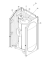
- FIG. 2 is a perspective view showing the machine room 2a of the outdoor unit 2 according to the first embodiment.
- the outdoor unit 2 is divided into a ventilation chamber (not shown) in which an outdoor blower 9 and the like are provided, and a machine room 2a in which a compressor 6 and the like are provided.
- the machine room 2a is surrounded by a wall 2b, and a compressor 6 extending in the vertical direction is placed therein.
- a soundproofing device 20 is provided on the compressor 6 and the wall 2b.
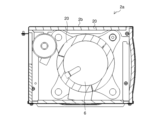
- FIG. 3 is a top view showing the machine room 2a of the outdoor unit 2 according to the first embodiment.
- three soundproof devices 20 are provided around the outer periphery of the compressor 6.
- the three soundproofing devices 20 are each bent into a circular arc shape with an angle of about 120°, and the respective ends face each other to form a pseudo circular shape. Thereby, the three soundproof devices 20 are wound so as to cover the entire outer circumference of the compressor 6.
- the soundproofing device 20 provided on the wall 2b is provided along the wall 2b.
- FIG. 4 is a side sectional view showing the soundproofing device 20 according to the first embodiment.
- the soundproofing device 20 includes a damping rubber plate 30, a low-density felt material 40, a high-density felt material 50, and a resonance rubber plate 60.
- vibration damping rubber plate 30 limits vibration and is a plate material made of elastic rubber.
- the low-density felt material 40 is a sound-absorbing felt material with a relatively low density.
- the low-density felt material 40 is provided on the other surface of the damping rubber plate 30.
- the low-density felt material 40 generates friction between its fibers when sound passes through it, converts the energy of the sound into frictional heat, and reduces the sound. Therefore, the low-density felt material 40 has high sound absorption performance in the middle and high frequency ranges.
- the low-density felt material 40 has a box shape 41. As a result, an air layer 42 in which air flows is formed inside the low-density felt material 40.
- the thickness of the bottom surface 40a of the low-density felt material 40 is greater than or equal to a predetermined thickness threshold. In this way, the thickness of the bottom surface 40a of the box-shaped low-density felt material 40 makes it possible to ensure sound absorption in the middle and high frequency ranges.
- the high-density felt material 50 is a sound-absorbing felt material having a higher density than the low-density felt material 40.
- the high-density felt material 50 is provided on the low-density felt material 40.
- the high-density felt material 50 generates friction between fibers when sound passes through it, converts the energy of the sound into frictional heat, and reduces the sound. It is. Therefore, like the low-density felt material 40, the high-density felt material 50 also has high sound absorption performance in the mid-range and high-frequency ranges.
- the thickness of the high-density felt material 50 is thinner than the thickness of the low-density felt material 40. Note that the low-density felt material 40, the air layer 42, and the high-density felt material 50 are collectively referred to as an air fluidized bed 70.
- FIG. 5 is a perspective view of the soundproofing device 20 according to the first embodiment seen from the front.
- the resonance rubber plate 60 is a plate material made of elastic rubber, which is provided on the high-density felt material 50 and has a plurality of openings 61 formed therein. As shown in FIG. 5, openings 61 are formed at equal intervals in the resonance rubber plate 60, and when sound passes through the openings 61, the air present in the openings 61 vibrates, causing friction. occurs, and sound absorption in the low frequency range is achieved.
- the soundproofing device 20 is attached to the compressor 6, the wall 2b, etc. by pasting one surface of the resonance rubber plate 60 to the compressor 6, the wall 2b, etc.
- a felt material or the like may be separately interposed between the resonance rubber plate 60 and the compressor 6. Thereby, compared to the case where the resonance rubber plate 60 is closely attached to the compressor 6, inhibition of air vibration can be suppressed.
- FIG. 6 is a perspective view of the soundproofing device 20 according to the first embodiment, seen from the back side.
- the damping rubber plate 30 is omitted.
- the soundproofing device 20 has a plurality of box shapes 41. The strength of the soundproofing device 20 is ensured by forming a plurality of small box shapes 41 in this way, instead of forming one large box shape 41.
- a low-density felt material 40 and a high-density felt material 50 having a higher density than the low-density felt material 40 are provided. Therefore, even if the high-density felt material 50 is made thinner to reduce costs, it has higher sound absorption performance than the low-density felt material 40 of the same thickness. Therefore, by using the high-density felt material 50 in areas with a high sound-absorbing effect, it is possible to increase the sound-absorbing effect in the low-frequency range while maintaining the sound-absorbing effect in the mid-range and high-frequency range without adding cost.
- the soundproofing device 20 when sound passes through the resonant rubber plate 60, the air in the opening 61 causes resonance vibration.
- the opening 61 allows the air to flow greatly due to the compression of the air that occurs when sound is transmitted. For this reason, by lining the resonant rubber plate 60 with the high-density felt material 50 having high sound absorption performance, the generated frictional heat increases more than when the same volume is made of ordinary felt material that is not high in density. Therefore, the sound absorption performance in the low frequency range is improved.
- the thickness of the high-density felt material 50 is thinner than the thickness of the low-density felt material 40.
- the price of high density felt material 50 is higher than the price of low density felt material 40.
- the low density felt material 40 has a box shape 41. Thereby, the volume of the air layer 42 formed in the low-density felt material 40 can be increased at low cost. When the air layer 42 expands, the frequency that causes resonance vibration becomes smaller, so that it is possible to adjust the resonance vibration to occur in the bass range. Since it is not necessary to increase the thickness of the low-density felt material 40 in order to improve sound absorption performance in the low frequency range, the amount of the low-density felt material 40 used can be reduced.
- the thickness of the bottom surface 40a of the low-density felt material 40 is greater than or equal to a predetermined thickness threshold. Thereby, it is possible to ensure the thickness of the low-density felt material 40 that absorbs sounds in the medium and high frequency ranges having short wavelengths.
- Air conditioner 1 Air conditioner, 2 Outdoor unit, 2a Machine room, 2b Wall, 3 Indoor unit, 4 Refrigerant circuit, 5 Refrigerant piping, 6 Compressor, 7 Flow path switching device, 8 Outdoor heat exchanger, 9 Outdoor blower, 10 Expansion Part, 11 indoor heat exchanger, 12 indoor blower, 20 soundproofing device, 30 damping rubber plate, 40 low density felt material, 40a bottom surface, 41 box shape, 42 air layer, 50 high density felt material, 60 resonance rubber plate, 61 Opening, 70 Air fluidized bed.
Abstract
防音装置は、振動を制限する制振ゴム板と、制振ゴム板に設けられた低密度フェルト材と、低密度フェルト材に設けられ、低密度フェルト材よりも密度が高い高密度フェルト材と、高密度フェルト材に設けられ、複数の開口部が形成された共鳴ゴム板と、を備える。
Description
本開示は、音を抑制する防音装置及び圧縮機に関する。
従来、防音装置として、振動を抑制する制振ゴム板に、音を吸収する吸音フェルト材が取り付けられた構造が一般的に知られている。吸音フェルト材は、音が自身を通過する際に、繊維間に摩擦を発生させ、音が有するエネルギーを摩擦熱に変換して、音を小さくするものである。しかし、低音域の音は波長が長いため、フェルト材を通過する際に発生する空気の振動が小さくなってしまう。このため、吸音フェルト材は、中音域及び高音域の吸音性能は高いが、低音域の吸音性能は高くない。
ここで、室外機に設けられた圧縮機の運転音は、空気調和機において発生する騒音の主な要因の一つであり、幅広い周波数成分を有する。従来の防音装置が圧縮機に取り付けられても、吸音フェルト材における低音域の吸音性能は高くないため、低音域の騒音を抑制することが困難である。
低音域の吸音性能を高めることを目的として、特許文献1には、吸音フェルト材及び制振ゴム板に共鳴ゴム板が取り付けられた三重構造の防音装置が開示されている。共鳴ゴム板には、等間隔に開口部が形成されており、音が開口部を通過する際に開口部に存在する空気が振動することによって、摩擦が発生し、低音域の吸音が実現される。これは、特定の周波数成分を持つ音が共鳴ゴム板の開口部を通過する際に発生する空気の圧縮と、空気の圧縮による内圧の上昇が要因で起こる反発とが交互に起こるヘルムホルツ共鳴の仕組みを利用するものである。共鳴ゴム板の開口部の空気が振動し、開口部の制振ゴムと開口部の吸音フェルト材との間で摩擦が発生するため、音が小さくなる。
しかしながら、特許文献1に開示された防音装置は、共鳴ゴム板と制振ゴム板との間の吸音フェルト材の厚みが吸音性能に影響を与えるため、低音域の吸音作用を高めようとすると吸音フェルト材を厚くしなければならず、コストがかかる。一方、吸音フェルト層を薄くしてコストを抑えようとすると、低音域の吸音作用が不十分になる。
本開示は、上記のような課題を解決するためになされたもので、コストをかけずに、中音域及び高音域の吸音作用を維持しつつ低音域の吸音作用を高める防音装置及び圧縮機を提供するものである。
本開示に係る防音装置は、振動を制限する制振ゴム板と、制振ゴム板に設けられた低密度フェルト材と、低密度フェルト材に設けられ、低密度フェルト材よりも密度が高い高密度フェルト材と、高密度フェルト材に設けられ、複数の開口部が形成された共鳴ゴム板と、を備える。
本開示によれば、低密度フェルト材と、低密度フェルト材よりも密度が高い高密度フェルト材とを備えている。このため、高密度フェルト材を薄くしてコストを抑えても、同じ厚さの低密度フェルト材よりも吸音性能が高い。従って、吸音効果が高い部分に高密度フェルト材を使用することによって、コストをかけずに、中音域及び高音域の吸音作用を維持しつつ低音域の吸音作用を高めることができる。
以下、本開示の防音装置の実施の形態について、図面を参照しながら説明する。なお、本開示は、以下に説明する実施の形態によって限定されるものではない。また、図1を含め、以下の図面では各構成部材の大きさの関係が実際のものとは異なる場合がある。また、以下の説明において、本開示の理解を容易にするために方向を表す用語を適宜用いるが、これは本開示を説明するためのものであって、これらの用語は本開示を限定するものではない。方向を表す用語としては、例えば、「上」、「下」、「右」、「左」、「前」又は「後」等が挙げられる。
実施の形態1.
図1は、実施の形態1に係る空気調和機1を示す回路図である。空気調和機1は、空調対象空間の空気を調整する装置であり、図1に示すように、室外機2と、室内機3とを備えている。室外機2には、例えば圧縮機6、流路切替装置7、室外熱交換器8及び室外送風機9が設けられている。室内機3には、例えば膨張部10、室内熱交換器11及び室内送風機12が設けられている。
図1は、実施の形態1に係る空気調和機1を示す回路図である。空気調和機1は、空調対象空間の空気を調整する装置であり、図1に示すように、室外機2と、室内機3とを備えている。室外機2には、例えば圧縮機6、流路切替装置7、室外熱交換器8及び室外送風機9が設けられている。室内機3には、例えば膨張部10、室内熱交換器11及び室内送風機12が設けられている。
圧縮機6、流路切替装置7、室外熱交換器8、膨張部10及び室内熱交換器11が冷媒配管5により接続されて冷媒回路4が構成されている。圧縮機6は、低温且つ低圧の状態の冷媒を吸入し、吸入した冷媒を圧縮して高温且つ高圧の状態の冷媒にして吐出するものである。圧縮機6は、例えば容量制御可能なインバータ圧縮機である。流路切替装置7は、冷媒回路4において冷媒が流れる方向を切り替えるものであり、例えば四方弁である。室外熱交換器8は、例えば室外空気と冷媒との間で熱交換するものである。室外熱交換器8は、冷房運転時には凝縮器として作用し、暖房運転時には蒸発器として作用する。膨張部10は、冷媒を減圧して膨張する減圧弁又は膨張弁である。膨張部10は、例えば開度が調整される電子式膨張弁である。
室内熱交換器11は、例えば室内空気と冷媒との間で熱交換するものである。室内熱交換器11は、冷房運転時には蒸発器として作用し、暖房運転時には凝縮器として作用する。室内送風機12は、室内熱交換器11に室内空気を送る機器である。
(運転モード、冷房運転)
次に、空気調和機1の運転モードについて説明する。先ず、冷房運転について説明する。冷房運転において、圧縮機6に吸入された冷媒は、圧縮機6によって圧縮されて高温且つ高圧のガス状態で吐出する。圧縮機6から吐出された高温且つ高圧のガス状態の冷媒は、流路切替装置7を通過して、凝縮器として作用する室外熱交換器8に流入し、室外熱交換器8において、室外送風機9によって送られる室外空気と熱交換されて凝縮して液化する。凝縮された液状態の冷媒は、膨張部10に流入し、膨張部10において膨張及び減圧されて低温且つ低圧の気液二相状態の冷媒となる。そして、気液二相状態の冷媒は、蒸発器として作用する室内熱交換器11に流入し、室内熱交換器11において、室内送風機12によって送られる室内空気と熱交換されて蒸発してガス化する。このとき、室内空気が冷やされ、室内において冷房が実施される。蒸発した低温且つ低圧のガス状態の冷媒は、流路切替装置7を通過して、圧縮機6に吸入される。
次に、空気調和機1の運転モードについて説明する。先ず、冷房運転について説明する。冷房運転において、圧縮機6に吸入された冷媒は、圧縮機6によって圧縮されて高温且つ高圧のガス状態で吐出する。圧縮機6から吐出された高温且つ高圧のガス状態の冷媒は、流路切替装置7を通過して、凝縮器として作用する室外熱交換器8に流入し、室外熱交換器8において、室外送風機9によって送られる室外空気と熱交換されて凝縮して液化する。凝縮された液状態の冷媒は、膨張部10に流入し、膨張部10において膨張及び減圧されて低温且つ低圧の気液二相状態の冷媒となる。そして、気液二相状態の冷媒は、蒸発器として作用する室内熱交換器11に流入し、室内熱交換器11において、室内送風機12によって送られる室内空気と熱交換されて蒸発してガス化する。このとき、室内空気が冷やされ、室内において冷房が実施される。蒸発した低温且つ低圧のガス状態の冷媒は、流路切替装置7を通過して、圧縮機6に吸入される。
(運転モード、暖房運転)
次に、暖房運転について説明する。暖房運転において、圧縮機6に吸入された冷媒は、圧縮機6によって圧縮されて高温且つ高圧のガス状態で吐出する。圧縮機6から吐出された高温且つ高圧のガス状態の冷媒は、流路切替装置7を通過して、凝縮器として作用する室内熱交換器11に流入し、室内熱交換器11において、室内送風機12によって送られる室内空気と熱交換されて凝縮して液化する。このとき、室内空気が暖められ、室内において暖房が実施される。凝縮された液状態の冷媒は、膨張部10に流入し、膨張部10において膨張及び減圧されて低温且つ低圧の気液二相状態の冷媒となる。そして、気液二相状態の冷媒は、蒸発器として作用する室外熱交換器8に流入し、室外熱交換器8において、室外送風機9によって送られる室外空気と熱交換されて蒸発してガス化する。蒸発した低温且つ低圧のガス状態の冷媒は、流路切替装置7を通過して、圧縮機6に吸入される。
次に、暖房運転について説明する。暖房運転において、圧縮機6に吸入された冷媒は、圧縮機6によって圧縮されて高温且つ高圧のガス状態で吐出する。圧縮機6から吐出された高温且つ高圧のガス状態の冷媒は、流路切替装置7を通過して、凝縮器として作用する室内熱交換器11に流入し、室内熱交換器11において、室内送風機12によって送られる室内空気と熱交換されて凝縮して液化する。このとき、室内空気が暖められ、室内において暖房が実施される。凝縮された液状態の冷媒は、膨張部10に流入し、膨張部10において膨張及び減圧されて低温且つ低圧の気液二相状態の冷媒となる。そして、気液二相状態の冷媒は、蒸発器として作用する室外熱交換器8に流入し、室外熱交換器8において、室外送風機9によって送られる室外空気と熱交換されて蒸発してガス化する。蒸発した低温且つ低圧のガス状態の冷媒は、流路切替装置7を通過して、圧縮機6に吸入される。
なお、空気調和機1は、流路切替装置7を有していなくてもよい。この場合、空気調和機1は、冷房専用機又は暖房専用機となる。なお、本実施の形態1では、膨張部10が室内機3に設けられている場合について例示しているが、膨張部10が室外機2に設けられていてもよい。また、膨張部10が、室内機3及び室外機2のいずれにも設けられていてもよい。この場合、室内機3の膨張部10は、冷媒を膨張及び減圧することによって気液二相状態にする機能を有し、室外機2の膨張部10は、複数の室外機2が組み合わされたときに冷媒が逆流することを抑制する機能を有する。
(機械室2a)
図2は、実施の形態1に係る室外機2の機械室2aを示す斜視図である。室外機2には、室外送風機9等が設けられる送風室(図示せず)と、圧縮機6等が設けられる機械室2aとに区画されている。図2に示すように、機械室2aは、壁2bに囲まれており、上下方向に延びる圧縮機6が載置されている。ここで、圧縮機6及び壁2bには、防音装置20が設けられている。
図2は、実施の形態1に係る室外機2の機械室2aを示す斜視図である。室外機2には、室外送風機9等が設けられる送風室(図示せず)と、圧縮機6等が設けられる機械室2aとに区画されている。図2に示すように、機械室2aは、壁2bに囲まれており、上下方向に延びる圧縮機6が載置されている。ここで、圧縮機6及び壁2bには、防音装置20が設けられている。
図3は、実施の形態1に係る室外機2の機械室2aを示す上面図である。図3に示すように、圧縮機6の外周には、3つの防音装置20が設けられている。3つの防音装置20は、それぞれ角度約120°の円弧状に曲げられ、それぞれの端部を向かい合わせることによって、疑似的な円状となっている。これにより、3つの防音装置20が圧縮機6の外周の全周を覆うように巻かれている。壁2bに設けられた防音装置20は、壁2bに沿って設けられている。
(防音装置20)
図4は、実施の形態1に係る防音装置20を示す側面断面図である。図4に示すように、防音装置20は、制振ゴム板30と、低密度フェルト材40と、高密度フェルト材50と、共鳴ゴム板60とを備えている。
図4は、実施の形態1に係る防音装置20を示す側面断面図である。図4に示すように、防音装置20は、制振ゴム板30と、低密度フェルト材40と、高密度フェルト材50と、共鳴ゴム板60とを備えている。
(制振ゴム板30)
制振ゴム板30は、振動を制限するものであり、弾性を有するゴムからなる板材である。
制振ゴム板30は、振動を制限するものであり、弾性を有するゴムからなる板材である。
(低密度フェルト材40)
低密度フェルト材40は、比較的密度が低い吸音フェルト材である。低密度フェルト材40は、制振ゴム板30の他面に設けられている。低密度フェルト材40は、音が自身を通過する際に、繊維間に摩擦を発生させ、音が有するエネルギーを摩擦熱に変換して、音を小さくするものである。このため、低密度フェルト材40は、中音域及び高音域の吸音性能が高い。本実施の形態1では、低密度フェルト材40は、箱形状41をなしている。これにより、低密度フェルト材40の内部には空気が流動する空気層42が形成されている。また、低密度フェルト材40の底面40aの厚さは、予め決められた厚さ閾値以上の厚さである。このように、箱形状41の低密度フェルト材40の底面40aに厚みがあることによって、中音域及び高音域の吸音性を担保することができる。
低密度フェルト材40は、比較的密度が低い吸音フェルト材である。低密度フェルト材40は、制振ゴム板30の他面に設けられている。低密度フェルト材40は、音が自身を通過する際に、繊維間に摩擦を発生させ、音が有するエネルギーを摩擦熱に変換して、音を小さくするものである。このため、低密度フェルト材40は、中音域及び高音域の吸音性能が高い。本実施の形態1では、低密度フェルト材40は、箱形状41をなしている。これにより、低密度フェルト材40の内部には空気が流動する空気層42が形成されている。また、低密度フェルト材40の底面40aの厚さは、予め決められた厚さ閾値以上の厚さである。このように、箱形状41の低密度フェルト材40の底面40aに厚みがあることによって、中音域及び高音域の吸音性を担保することができる。
(高密度フェルト材50)
高密度フェルト材50は、低密度フェルト材40よりも密度が高い吸音フェルト材である。高密度フェルト材50は、低密度フェルト材40に設けられている。高密度フェルト材50は、低密度フェルト材40と同様に、音が自身を通過する際に、繊維間に摩擦を発生させ、音が有するエネルギーを摩擦熱に変換して、音を小さくするものである。このため、高密度フェルト材50も、低密度フェルト材40と同様に中音域及び高音域の吸音性能が高い。ここで、高密度フェルト材50の厚さは、低密度フェルト材40の厚さよりも薄い。なお、低密度フェルト材40、空気層42及び高密度フェルト材50をまとめて、空気流動層70と呼称する。
高密度フェルト材50は、低密度フェルト材40よりも密度が高い吸音フェルト材である。高密度フェルト材50は、低密度フェルト材40に設けられている。高密度フェルト材50は、低密度フェルト材40と同様に、音が自身を通過する際に、繊維間に摩擦を発生させ、音が有するエネルギーを摩擦熱に変換して、音を小さくするものである。このため、高密度フェルト材50も、低密度フェルト材40と同様に中音域及び高音域の吸音性能が高い。ここで、高密度フェルト材50の厚さは、低密度フェルト材40の厚さよりも薄い。なお、低密度フェルト材40、空気層42及び高密度フェルト材50をまとめて、空気流動層70と呼称する。
(共鳴ゴム板60)
図5は、実施の形態1に係る防音装置20を示す表面からみた斜視図である。共鳴ゴム板60は、高密度フェルト材50に設けられ、複数の開口部61が形成された弾性を有するゴムからなる板材である。図5に示すように、共鳴ゴム板60には、等間隔に開口部61が形成されており、音が開口部61を通過する際に開口部61に存在する空気が振動することによって、摩擦が発生し、低音域の吸音が実現される。これは、特定の周波数成分を持つ音が共鳴ゴム板60の開口部61を通過する際に発生する空気の圧縮と、空気の圧縮による内圧の上昇が要因で起こる反発とが交互に起こるヘルムホルツ共鳴の仕組みを利用するものである。共鳴ゴム板60の開口部61の空気が振動し、開口部61の制振ゴム板30と開口部61の高密度フェルト材50との間で摩擦が発生するため、音が小さくなる。ここで、共鳴ゴム板60の一面が、圧縮機6又は壁2b等に貼り付けられることによって、圧縮機6又は壁2b等に防音装置20が取り付けられる。なお、共鳴ゴム板60と圧縮機6との間に、別途フェルト材等を介在させてもよい。これにより、圧縮機6に共鳴ゴム板60が密着して貼り付けられる場合に比べて、空気の振動の阻害を抑制することができる。
図5は、実施の形態1に係る防音装置20を示す表面からみた斜視図である。共鳴ゴム板60は、高密度フェルト材50に設けられ、複数の開口部61が形成された弾性を有するゴムからなる板材である。図5に示すように、共鳴ゴム板60には、等間隔に開口部61が形成されており、音が開口部61を通過する際に開口部61に存在する空気が振動することによって、摩擦が発生し、低音域の吸音が実現される。これは、特定の周波数成分を持つ音が共鳴ゴム板60の開口部61を通過する際に発生する空気の圧縮と、空気の圧縮による内圧の上昇が要因で起こる反発とが交互に起こるヘルムホルツ共鳴の仕組みを利用するものである。共鳴ゴム板60の開口部61の空気が振動し、開口部61の制振ゴム板30と開口部61の高密度フェルト材50との間で摩擦が発生するため、音が小さくなる。ここで、共鳴ゴム板60の一面が、圧縮機6又は壁2b等に貼り付けられることによって、圧縮機6又は壁2b等に防音装置20が取り付けられる。なお、共鳴ゴム板60と圧縮機6との間に、別途フェルト材等を介在させてもよい。これにより、圧縮機6に共鳴ゴム板60が密着して貼り付けられる場合に比べて、空気の振動の阻害を抑制することができる。
図6は、実施の形態1に係る防音装置20を示す裏面からみた斜視図である。図6では、制振ゴム板30が省略されている。図6に示すように、防音装置20は、複数の箱形状41を有している。大きい箱形状41が一つ形成されるのではなく、このように、小分けにして小さい箱形状41が複数形成されることによって、防音装置20の強度を確保している。
本実施の形態1によれば、低密度フェルト材40と、低密度フェルト材40よりも密度が高い高密度フェルト材50とを備えている。このため、高密度フェルト材50を薄くしてコストを抑えても、同じ厚さの低密度フェルト材40よりも吸音性能が高い。従って、吸音効果が高い部分に高密度フェルト材50を使用することによって、コストをかけずに、中音域及び高音域の吸音作用を維持しつつ低音域の吸音作用を高めることができる。防音装置20は、音が共鳴ゴム板60を通過する際、開口部61の空気が振動する共鳴振動を起こす。開口部61は、音が伝達する際に発生する空気の圧縮によって空気を大きく流動させる。このため、共鳴ゴム板60に吸音性能が高い高密度フェルト材50が裏打ちされることによって、密度が高くない通常のフェルト材を同体積とするよりも、発生する摩擦熱が増加する。従って、低音域の吸音性能が高くなる。
また、高密度フェルト材50の厚さは、低密度フェルト材40の厚さよりも薄い。概して、高密度フェルト材50の価格は、低密度フェルト材40の価格よりも高い。高密度フェルト材50の厚さを薄くすることによって、共鳴ゴム板60の開口部61を通過する空気が振動する際に発生する摩擦熱を安価に増やすことができる。
更に、低密度フェルト材40は、箱形状41をなしている。これにより、低密度フェルト材40に形成される空気層42の体積を安価に増加させることができる。空気層42が広がると、共鳴振動を起こす周波数が小さくなるため、低音域で共鳴振動を起こすように調整することができる。低音域の吸音性能を向上させるために低密度フェルト材40を厚くする必要がないため、低密度フェルト材40の使用量を少なくすることができる。
そして、低密度フェルト材40の底面40aの厚さは、予め決められた厚さ閾値以上の厚さである。これにより、波長が短い中音域及び高音域の音を吸収する低密度フェルト材40の厚さを確保することができる。
以上説明したように、2つの密度を有するフェルト材を組み合わせることによって、均一の密度のフェルト材を利用するよりも、高い吸音性能を得ることができる。概して、密度とコストとは比例関係にある。このため、高密度フェルト材50の使用量を最小限に留め、安価な低密度フェルト材40の厚さを調整することによって、コストを抑えることができる。即ち、フェルト材が備える中音域及び高音域の吸音性能を維持しつつ、共鳴ゴム板60による低音域の吸音性能を安価に得ることができる。
1 空気調和機、2 室外機、2a 機械室、2b 壁、3 室内機、4 冷媒回路、5 冷媒配管、6 圧縮機、7 流路切替装置、8 室外熱交換器、9 室外送風機、10 膨張部、11 室内熱交換器、12 室内送風機、20 防音装置、30 制振ゴム板、40 低密度フェルト材、40a 底面、41 箱形状、42 空気層、50 高密度フェルト材、60 共鳴ゴム板、61 開口部、70 空気流動層。
Claims (5)
- 振動を制限する制振ゴム板と、
前記制振ゴム板に設けられた低密度フェルト材と、
前記低密度フェルト材に設けられ、前記低密度フェルト材よりも密度が高い高密度フェルト材と、
前記高密度フェルト材に設けられ、複数の開口部が形成された共鳴ゴム板と、
を備える防音装置。 - 前記高密度フェルト材の厚さは、前記低密度フェルト材の厚さよりも薄い
請求項1記載の防音装置。 - 前記低密度フェルト材は、箱形状をなしている
請求項1又は2記載の防音装置。 - 前記低密度フェルト材の底面の厚さは、予め決められた厚さ閾値以上の厚さである
請求項1~3のいずれか1項に記載の防音装置。 - 請求項1~4のいずれか1項に記載の防音装置を
備える圧縮機。
Priority Applications (1)
| Application Number | Priority Date | Filing Date | Title |
|---|---|---|---|
| PCT/JP2022/026135 WO2024004115A1 (ja) | 2022-06-30 | 2022-06-30 | 防音装置及び圧縮機 |
Applications Claiming Priority (1)
| Application Number | Priority Date | Filing Date | Title |
|---|---|---|---|
| PCT/JP2022/026135 WO2024004115A1 (ja) | 2022-06-30 | 2022-06-30 | 防音装置及び圧縮機 |
Publications (1)
| Publication Number | Publication Date |
|---|---|
| WO2024004115A1 true WO2024004115A1 (ja) | 2024-01-04 |
Family
ID=89382255
Family Applications (1)
| Application Number | Title | Priority Date | Filing Date |
|---|---|---|---|
| PCT/JP2022/026135 WO2024004115A1 (ja) | 2022-06-30 | 2022-06-30 | 防音装置及び圧縮機 |
Country Status (1)
| Country | Link |
|---|---|
| WO (1) | WO2024004115A1 (ja) |
Citations (3)
| Publication number | Priority date | Publication date | Assignee | Title |
|---|---|---|---|---|
| JPH03104460U (ja) * | 1990-02-16 | 1991-10-30 | ||
| JPH1073288A (ja) * | 1996-08-29 | 1998-03-17 | Oshitani Felt Kasei Kk | 防音防振性に優れた空調機用室外機用コンプレッサカバー |
| JP2005335684A (ja) * | 2004-04-28 | 2005-12-08 | Takehiro:Kk | 超軽量な防音材 |
-
2022
- 2022-06-30 WO PCT/JP2022/026135 patent/WO2024004115A1/ja unknown
Patent Citations (3)
| Publication number | Priority date | Publication date | Assignee | Title |
|---|---|---|---|---|
| JPH03104460U (ja) * | 1990-02-16 | 1991-10-30 | ||
| JPH1073288A (ja) * | 1996-08-29 | 1998-03-17 | Oshitani Felt Kasei Kk | 防音防振性に優れた空調機用室外機用コンプレッサカバー |
| JP2005335684A (ja) * | 2004-04-28 | 2005-12-08 | Takehiro:Kk | 超軽量な防音材 |
Similar Documents
| Publication | Publication Date | Title |
|---|---|---|
| KR101936192B1 (ko) | 공기조화기의 실외기 | |
| JP2005226987A (ja) | 空調機の室外ユニットの配管構造 | |
| JP2003176935A (ja) | 大型空気調和機の室外機用騒音低減構造 | |
| KR20050086273A (ko) | 에어컨 실외기의 배관 구조 | |
| WO2024004115A1 (ja) | 防音装置及び圧縮機 | |
| JP3107604U (ja) | 空気調和機室外機の騒音低減構造 | |
| CN215863765U (zh) | 空调室外机 | |
| JP2013088003A (ja) | 室外機 | |
| CN111247379B (zh) | 制冷循环装置用单元、制冷循环装置及电气设备 | |
| KR200154185Y1 (ko) | 공기조화기의 소음방지장치 | |
| JP2017172845A (ja) | 風路筐体及び空気調和装置 | |
| KR200154190Y1 (ko) | 공기조화기의 소음방지장치 | |
| KR200154189Y1 (ko) | 공기조화기의 소음방지장치 | |
| KR20040078938A (ko) | 에어컨 실외기용 베이스 플레이트의 포밍구조 | |
| KR102492664B1 (ko) | 냉장고 및 이에 설치되는 소음 저감 장치 | |
| CN216814404U (zh) | 空调室外机 | |
| JP7282263B2 (ja) | 空気調和機の室外機 | |
| KR100734487B1 (ko) | 멀티형 에어컨의 압축기 소음 전달 방지구조 | |
| CN218328411U (zh) | 空调器 | |
| KR102490582B1 (ko) | 방음장치 | |
| KR20210120681A (ko) | 공기조화기의 소음방지장치 | |
| KR20220013771A (ko) | 공기조화기 | |
| KR100606278B1 (ko) | 압축기의 차음부재 배치구조 | |
| CN114543192A (zh) | 空调室外机 | |
| JPH06229660A (ja) | 冷却貯蔵庫 |
Legal Events
| Date | Code | Title | Description |
|---|---|---|---|
| 121 | Ep: the epo has been informed by wipo that ep was designated in this application |
Ref document number: 22949389 Country of ref document: EP Kind code of ref document: A1 |