WO2024004115A1 - Dispositif d'insonorisation et compresseur - Google Patents
Dispositif d'insonorisation et compresseur Download PDFInfo
- Publication number
- WO2024004115A1 WO2024004115A1 PCT/JP2022/026135 JP2022026135W WO2024004115A1 WO 2024004115 A1 WO2024004115 A1 WO 2024004115A1 JP 2022026135 W JP2022026135 W JP 2022026135W WO 2024004115 A1 WO2024004115 A1 WO 2024004115A1
- Authority
- WO
- WIPO (PCT)
- Prior art keywords
- felt material
- low
- density
- density felt
- sound
- Prior art date
Links
- 239000000463 material Substances 0.000 claims abstract description 92
- 238000013016 damping Methods 0.000 claims abstract description 17
- 239000003507 refrigerant Substances 0.000 description 28
- 238000010521 absorption reaction Methods 0.000 description 16
- 230000000694 effects Effects 0.000 description 9
- 238000001816 cooling Methods 0.000 description 7
- 238000010438 heat treatment Methods 0.000 description 7
- 239000007788 liquid Substances 0.000 description 7
- 230000006835 compression Effects 0.000 description 5
- 238000007906 compression Methods 0.000 description 5
- 239000000835 fiber Substances 0.000 description 3
- 238000010586 diagram Methods 0.000 description 2
- 230000005764 inhibitory process Effects 0.000 description 1
- 238000009423 ventilation Methods 0.000 description 1
Images


Classifications
-
- G—PHYSICS
- G10—MUSICAL INSTRUMENTS; ACOUSTICS
- G10K—SOUND-PRODUCING DEVICES; METHODS OR DEVICES FOR PROTECTING AGAINST, OR FOR DAMPING, NOISE OR OTHER ACOUSTIC WAVES IN GENERAL; ACOUSTICS NOT OTHERWISE PROVIDED FOR
- G10K11/00—Methods or devices for transmitting, conducting or directing sound in general; Methods or devices for protecting against, or for damping, noise or other acoustic waves in general
- G10K11/16—Methods or devices for protecting against, or for damping, noise or other acoustic waves in general
- G10K11/162—Selection of materials
- G10K11/168—Plural layers of different materials, e.g. sandwiches
-
- G—PHYSICS
- G10—MUSICAL INSTRUMENTS; ACOUSTICS
- G10K—SOUND-PRODUCING DEVICES; METHODS OR DEVICES FOR PROTECTING AGAINST, OR FOR DAMPING, NOISE OR OTHER ACOUSTIC WAVES IN GENERAL; ACOUSTICS NOT OTHERWISE PROVIDED FOR
- G10K11/00—Methods or devices for transmitting, conducting or directing sound in general; Methods or devices for protecting against, or for damping, noise or other acoustic waves in general
- G10K11/16—Methods or devices for protecting against, or for damping, noise or other acoustic waves in general
- G10K11/172—Methods or devices for protecting against, or for damping, noise or other acoustic waves in general using resonance effects
Definitions
- the present disclosure relates to a soundproofing device and a compressor that suppress sound.
- a structure in which a sound-absorbing felt material that absorbs sound is attached to a damping rubber plate that suppresses vibration is generally known.
- Sound-absorbing felt materials generate friction between fibers when sound passes through them, converting the energy of the sound into frictional heat, thereby reducing the sound.
- the air vibrations generated when they pass through the felt material become smaller.
- the sound-absorbing felt material has high sound-absorbing performance in the mid-range and high-frequency ranges, but does not have high sound-absorbing performance in the low-frequency range.
- the operating sound of the compressor installed in the outdoor unit is one of the main causes of noise generated in air conditioners, and has a wide range of frequency components. Even if a conventional soundproofing device is attached to a compressor, it is difficult to suppress low-frequency noise because the sound-absorbing felt material does not have high sound-absorbing performance in the low-frequency range.
- Patent Document 1 discloses a soundproofing device with a triple structure in which a resonance rubber plate is attached to a sound-absorbing felt material and a vibration-damping rubber plate.
- the resonant rubber plate has openings formed at equal intervals, and when sound passes through the openings, the air present in the openings vibrates, creating friction and achieving sound absorption in the low frequency range.
- Ru This is a Helmholtz resonance mechanism in which air compression occurs when a sound with a specific frequency component passes through an opening in a resonant rubber plate, and repulsion occurs due to an increase in internal pressure due to air compression. It uses The air in the opening of the resonant rubber plate vibrates, and friction occurs between the vibration damping rubber in the opening and the sound-absorbing felt material in the opening, which reduces the sound.
- the thickness of the sound-absorbing felt material between the resonance rubber plate and the vibration-damping rubber plate affects the sound-absorbing performance.
- the felt material must be made thicker, which increases cost.
- an attempt is made to reduce the cost by making the sound-absorbing felt layer thinner the sound-absorbing effect in the low frequency range becomes insufficient.
- the present disclosure has been made in order to solve the above-mentioned problems, and provides a soundproofing device and a compressor that enhances the sound absorption effect in the low frequency range while maintaining the sound absorption effect in the midrange and high frequency ranges without increasing the cost. This is what we provide.
- the soundproofing device includes a damping rubber plate that limits vibration, a low-density felt material provided on the vibration-damping rubber plate, and a high density felt material provided on the low-density felt material and having a higher density than the low-density felt material.
- the device includes a high-density felt material and a resonant rubber plate provided in the high-density felt material and having a plurality of openings formed therein.
- a low-density felt material and a high-density felt material having a higher density than the low-density felt material are provided. Therefore, even if the high-density felt material is made thinner to reduce costs, it has higher sound absorption performance than a low-density felt material of the same thickness. Therefore, by using high-density felt material in areas with high sound-absorbing effects, the sound-absorbing effect in the low-frequency range can be enhanced while maintaining the sound-absorbing effect in the mid-range and high-frequency range without increasing costs.
- FIG. 1 is a circuit diagram showing an air conditioner according to Embodiment 1.
- FIG. FIG. 2 is a perspective view showing a machine room of the outdoor unit according to the first embodiment.
- FIG. 3 is a top view showing a machine room of the outdoor unit according to the first embodiment.
- 1 is a side sectional view showing a soundproofing device according to Embodiment 1.
- FIG. 1 is a perspective view of the soundproofing device according to Embodiment 1 seen from the front;
- FIG. FIG. 2 is a perspective view of the soundproofing device according to the first embodiment, seen from the back side.
- FIG. 1 is a circuit diagram showing an air conditioner 1 according to the first embodiment.
- the air conditioner 1 is a device that adjusts the air in a space to be air-conditioned, and includes an outdoor unit 2 and an indoor unit 3, as shown in FIG.
- the outdoor unit 2 is provided with, for example, a compressor 6, a flow path switching device 7, an outdoor heat exchanger 8, and an outdoor blower 9.
- the indoor unit 3 is provided with, for example, an expansion section 10, an indoor heat exchanger 11, and an indoor blower 12.
- a refrigerant circuit 4 is constructed by connecting a compressor 6, a flow path switching device 7, an outdoor heat exchanger 8, an expansion section 10, and an indoor heat exchanger 11 through a refrigerant pipe 5.
- the compressor 6 takes in refrigerant at low temperature and low pressure, compresses the sucked refrigerant, and discharges the refrigerant at high temperature and high pressure.
- the compressor 6 is, for example, an inverter compressor whose capacity can be controlled.
- the flow path switching device 7 switches the direction in which the refrigerant flows in the refrigerant circuit 4, and is, for example, a four-way valve.
- the outdoor heat exchanger 8 exchanges heat between, for example, outdoor air and a refrigerant.
- the outdoor heat exchanger 8 acts as a condenser during cooling operation, and acts as an evaporator during heating operation.
- the expansion section 10 is a pressure reducing valve or an expansion valve that reduces the pressure of the refrigerant and expands it.
- the expansion section 10 is, for example, an electronic expansion valve whose opening degree is adjusted.
- the indoor heat exchanger 11 exchanges heat between, for example, indoor air and a refrigerant.
- the indoor heat exchanger 11 acts as an evaporator during cooling operation, and acts as a condenser during heating operation.
- the indoor blower 12 is a device that sends indoor air to the indoor heat exchanger 11.
- the cooling operation will be explained.
- the refrigerant sucked into the compressor 6 is compressed by the compressor 6 and discharged in a high temperature and high pressure gas state.
- the high temperature and high pressure gaseous refrigerant discharged from the compressor 6 passes through the flow path switching device 7 and flows into the outdoor heat exchanger 8 which acts as a condenser. It exchanges heat with the outdoor air sent by 9, condenses and liquefies.
- the condensed liquid refrigerant flows into the expansion section 10, where it is expanded and depressurized to become a low-temperature, low-pressure gas-liquid two-phase refrigerant.
- the gas-liquid two-phase refrigerant then flows into the indoor heat exchanger 11 that acts as an evaporator, where it exchanges heat with the indoor air sent by the indoor blower 12, evaporates, and gasifies. do. At this time, indoor air is cooled and cooling is performed indoors.
- the evaporated low-temperature, low-pressure gaseous refrigerant passes through the flow path switching device 7 and is sucked into the compressor 6 .
- heating operation Next, heating operation will be explained.
- the refrigerant sucked into the compressor 6 is compressed by the compressor 6 and discharged in a high temperature and high pressure gas state.
- the high temperature and high pressure gaseous refrigerant discharged from the compressor 6 passes through the flow path switching device 7 and flows into the indoor heat exchanger 11 which acts as a condenser. It exchanges heat with indoor air sent by 12, condenses and liquefies. At this time, indoor air is warmed and heating is performed indoors.
- the condensed liquid refrigerant flows into the expansion section 10, where it is expanded and depressurized to become a low-temperature, low-pressure gas-liquid two-phase refrigerant.
- the gas-liquid two-phase refrigerant then flows into the outdoor heat exchanger 8 that acts as an evaporator, where it exchanges heat with the outdoor air sent by the outdoor blower 9 and evaporates into gas. do.
- the evaporated low-temperature, low-pressure gaseous refrigerant passes through the flow path switching device 7 and is sucked into the compressor 6 .
- the air conditioner 1 does not need to include the flow path switching device 7. In this case, the air conditioner 1 becomes a cooling-only machine or a heating-only machine.
- the expansion section 10 may be provided in the indoor unit 3.
- the expansion section 10 may be provided in both the indoor unit 3 and the outdoor unit 2.
- the expansion section 10 of the indoor unit 3 has the function of expanding and reducing the pressure of the refrigerant to bring it into a gas-liquid two-phase state
- the expansion section 10 of the outdoor unit 2 has the function of expanding and reducing the pressure of the refrigerant
- the expansion section 10 of the outdoor unit 2 has the function of expanding and reducing the pressure of the refrigerant. It sometimes has the function of suppressing the backflow of refrigerant.
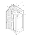
- FIG. 2 is a perspective view showing the machine room 2a of the outdoor unit 2 according to the first embodiment.
- the outdoor unit 2 is divided into a ventilation chamber (not shown) in which an outdoor blower 9 and the like are provided, and a machine room 2a in which a compressor 6 and the like are provided.
- the machine room 2a is surrounded by a wall 2b, and a compressor 6 extending in the vertical direction is placed therein.
- a soundproofing device 20 is provided on the compressor 6 and the wall 2b.
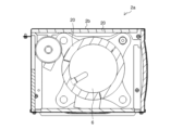
- FIG. 3 is a top view showing the machine room 2a of the outdoor unit 2 according to the first embodiment.
- three soundproof devices 20 are provided around the outer periphery of the compressor 6.
- the three soundproofing devices 20 are each bent into a circular arc shape with an angle of about 120°, and the respective ends face each other to form a pseudo circular shape. Thereby, the three soundproof devices 20 are wound so as to cover the entire outer circumference of the compressor 6.
- the soundproofing device 20 provided on the wall 2b is provided along the wall 2b.
- FIG. 4 is a side sectional view showing the soundproofing device 20 according to the first embodiment.
- the soundproofing device 20 includes a damping rubber plate 30, a low-density felt material 40, a high-density felt material 50, and a resonance rubber plate 60.
- vibration damping rubber plate 30 limits vibration and is a plate material made of elastic rubber.
- the low-density felt material 40 is a sound-absorbing felt material with a relatively low density.
- the low-density felt material 40 is provided on the other surface of the damping rubber plate 30.
- the low-density felt material 40 generates friction between its fibers when sound passes through it, converts the energy of the sound into frictional heat, and reduces the sound. Therefore, the low-density felt material 40 has high sound absorption performance in the middle and high frequency ranges.
- the low-density felt material 40 has a box shape 41. As a result, an air layer 42 in which air flows is formed inside the low-density felt material 40.
- the thickness of the bottom surface 40a of the low-density felt material 40 is greater than or equal to a predetermined thickness threshold. In this way, the thickness of the bottom surface 40a of the box-shaped low-density felt material 40 makes it possible to ensure sound absorption in the middle and high frequency ranges.
- the high-density felt material 50 is a sound-absorbing felt material having a higher density than the low-density felt material 40.
- the high-density felt material 50 is provided on the low-density felt material 40.
- the high-density felt material 50 generates friction between fibers when sound passes through it, converts the energy of the sound into frictional heat, and reduces the sound. It is. Therefore, like the low-density felt material 40, the high-density felt material 50 also has high sound absorption performance in the mid-range and high-frequency ranges.
- the thickness of the high-density felt material 50 is thinner than the thickness of the low-density felt material 40. Note that the low-density felt material 40, the air layer 42, and the high-density felt material 50 are collectively referred to as an air fluidized bed 70.
- FIG. 5 is a perspective view of the soundproofing device 20 according to the first embodiment seen from the front.
- the resonance rubber plate 60 is a plate material made of elastic rubber, which is provided on the high-density felt material 50 and has a plurality of openings 61 formed therein. As shown in FIG. 5, openings 61 are formed at equal intervals in the resonance rubber plate 60, and when sound passes through the openings 61, the air present in the openings 61 vibrates, causing friction. occurs, and sound absorption in the low frequency range is achieved.
- the soundproofing device 20 is attached to the compressor 6, the wall 2b, etc. by pasting one surface of the resonance rubber plate 60 to the compressor 6, the wall 2b, etc.
- a felt material or the like may be separately interposed between the resonance rubber plate 60 and the compressor 6. Thereby, compared to the case where the resonance rubber plate 60 is closely attached to the compressor 6, inhibition of air vibration can be suppressed.
- FIG. 6 is a perspective view of the soundproofing device 20 according to the first embodiment, seen from the back side.
- the damping rubber plate 30 is omitted.
- the soundproofing device 20 has a plurality of box shapes 41. The strength of the soundproofing device 20 is ensured by forming a plurality of small box shapes 41 in this way, instead of forming one large box shape 41.
- a low-density felt material 40 and a high-density felt material 50 having a higher density than the low-density felt material 40 are provided. Therefore, even if the high-density felt material 50 is made thinner to reduce costs, it has higher sound absorption performance than the low-density felt material 40 of the same thickness. Therefore, by using the high-density felt material 50 in areas with a high sound-absorbing effect, it is possible to increase the sound-absorbing effect in the low-frequency range while maintaining the sound-absorbing effect in the mid-range and high-frequency range without adding cost.
- the soundproofing device 20 when sound passes through the resonant rubber plate 60, the air in the opening 61 causes resonance vibration.
- the opening 61 allows the air to flow greatly due to the compression of the air that occurs when sound is transmitted. For this reason, by lining the resonant rubber plate 60 with the high-density felt material 50 having high sound absorption performance, the generated frictional heat increases more than when the same volume is made of ordinary felt material that is not high in density. Therefore, the sound absorption performance in the low frequency range is improved.
- the thickness of the high-density felt material 50 is thinner than the thickness of the low-density felt material 40.
- the price of high density felt material 50 is higher than the price of low density felt material 40.
- the low density felt material 40 has a box shape 41. Thereby, the volume of the air layer 42 formed in the low-density felt material 40 can be increased at low cost. When the air layer 42 expands, the frequency that causes resonance vibration becomes smaller, so that it is possible to adjust the resonance vibration to occur in the bass range. Since it is not necessary to increase the thickness of the low-density felt material 40 in order to improve sound absorption performance in the low frequency range, the amount of the low-density felt material 40 used can be reduced.
- the thickness of the bottom surface 40a of the low-density felt material 40 is greater than or equal to a predetermined thickness threshold. Thereby, it is possible to ensure the thickness of the low-density felt material 40 that absorbs sounds in the medium and high frequency ranges having short wavelengths.
- Air conditioner 1 Air conditioner, 2 Outdoor unit, 2a Machine room, 2b Wall, 3 Indoor unit, 4 Refrigerant circuit, 5 Refrigerant piping, 6 Compressor, 7 Flow path switching device, 8 Outdoor heat exchanger, 9 Outdoor blower, 10 Expansion Part, 11 indoor heat exchanger, 12 indoor blower, 20 soundproofing device, 30 damping rubber plate, 40 low density felt material, 40a bottom surface, 41 box shape, 42 air layer, 50 high density felt material, 60 resonance rubber plate, 61 Opening, 70 Air fluidized bed.
Landscapes
- Physics & Mathematics (AREA)
- Engineering & Computer Science (AREA)
- Acoustics & Sound (AREA)
- Multimedia (AREA)
- Compressor (AREA)
Abstract
Ce dispositif d'insonorisation est équipé : d'une plaque en caoutchouc d'amortissement qui limite les vibrations ; d'un matériau de feutre de faible densité disposé sur la plaque de caoutchouc d'amortissement ; d'un matériau de feutre de haute densité qui est disposé sur le matériau de feutre de faible densité et présente une densité supérieure à celle du matériau de feutre de faible densité ; et d'une plaque de caoutchouc résonant qui est disposée sur le matériau de feutre de haute densité et présente une pluralité d'ouvertures formées à l'intérieur.
Priority Applications (1)
| Application Number | Priority Date | Filing Date | Title |
|---|---|---|---|
| PCT/JP2022/026135 WO2024004115A1 (fr) | 2022-06-30 | 2022-06-30 | Dispositif d'insonorisation et compresseur |
Applications Claiming Priority (1)
| Application Number | Priority Date | Filing Date | Title |
|---|---|---|---|
| PCT/JP2022/026135 WO2024004115A1 (fr) | 2022-06-30 | 2022-06-30 | Dispositif d'insonorisation et compresseur |
Publications (1)
| Publication Number | Publication Date |
|---|---|
| WO2024004115A1 true WO2024004115A1 (fr) | 2024-01-04 |
Family
ID=89382255
Family Applications (1)
| Application Number | Title | Priority Date | Filing Date |
|---|---|---|---|
| PCT/JP2022/026135 WO2024004115A1 (fr) | 2022-06-30 | 2022-06-30 | Dispositif d'insonorisation et compresseur |
Country Status (1)
| Country | Link |
|---|---|
| WO (1) | WO2024004115A1 (fr) |
Citations (3)
| Publication number | Priority date | Publication date | Assignee | Title |
|---|---|---|---|---|
| JPH03104460U (fr) * | 1990-02-16 | 1991-10-30 | ||
| JPH1073288A (ja) * | 1996-08-29 | 1998-03-17 | Oshitani Felt Kasei Kk | 防音防振性に優れた空調機用室外機用コンプレッサカバー |
| JP2005335684A (ja) * | 2004-04-28 | 2005-12-08 | Takehiro:Kk | 超軽量な防音材 |
-
2022
- 2022-06-30 WO PCT/JP2022/026135 patent/WO2024004115A1/fr unknown
Patent Citations (3)
| Publication number | Priority date | Publication date | Assignee | Title |
|---|---|---|---|---|
| JPH03104460U (fr) * | 1990-02-16 | 1991-10-30 | ||
| JPH1073288A (ja) * | 1996-08-29 | 1998-03-17 | Oshitani Felt Kasei Kk | 防音防振性に優れた空調機用室外機用コンプレッサカバー |
| JP2005335684A (ja) * | 2004-04-28 | 2005-12-08 | Takehiro:Kk | 超軽量な防音材 |
Similar Documents
| Publication | Publication Date | Title |
|---|---|---|
| KR101936192B1 (ko) | 공기조화기의 실외기 | |
| JP2005226987A (ja) | 空調機の室外ユニットの配管構造 | |
| JP2003176935A (ja) | 大型空気調和機の室外機用騒音低減構造 | |
| KR20050086273A (ko) | 에어컨 실외기의 배관 구조 | |
| WO2024004115A1 (fr) | Dispositif d'insonorisation et compresseur | |
| JP3107604U (ja) | 空気調和機室外機の騒音低減構造 | |
| CN215863765U (zh) | 空调室外机 | |
| JP2013088003A (ja) | 室外機 | |
| CN111247379B (zh) | 制冷循环装置用单元、制冷循环装置及电气设备 | |
| KR200154185Y1 (ko) | 공기조화기의 소음방지장치 | |
| JP2017172845A (ja) | 風路筐体及び空気調和装置 | |
| KR200154189Y1 (ko) | 공기조화기의 소음방지장치 | |
| KR20040078938A (ko) | 에어컨 실외기용 베이스 플레이트의 포밍구조 | |
| KR102492664B1 (ko) | 냉장고 및 이에 설치되는 소음 저감 장치 | |
| CN216814404U (zh) | 空调室外机 | |
| JP7282263B2 (ja) | 空気調和機の室外機 | |
| KR100734487B1 (ko) | 멀티형 에어컨의 압축기 소음 전달 방지구조 | |
| CN218328411U (zh) | 空调器 | |
| KR102490582B1 (ko) | 방음장치 | |
| KR20210120681A (ko) | 공기조화기의 소음방지장치 | |
| KR200142965Y1 (ko) | 공조기기용 실외기 | |
| KR19980052877U (ko) | 공기조화기의 소음방지장치 | |
| KR200244987Y1 (ko) | 압축기 소음 차단을 위한 배플 구조 | |
| KR20220013771A (ko) | 공기조화기 | |
| KR100606278B1 (ko) | 압축기의 차음부재 배치구조 |
Legal Events
| Date | Code | Title | Description |
|---|---|---|---|
| 121 | Ep: the epo has been informed by wipo that ep was designated in this application |
Ref document number: 22949389 Country of ref document: EP Kind code of ref document: A1 |