WO2024004038A1 - 異物除去装置 - Google Patents
異物除去装置 Download PDFInfo
- Publication number
- WO2024004038A1 WO2024004038A1 PCT/JP2022/025783 JP2022025783W WO2024004038A1 WO 2024004038 A1 WO2024004038 A1 WO 2024004038A1 JP 2022025783 W JP2022025783 W JP 2022025783W WO 2024004038 A1 WO2024004038 A1 WO 2024004038A1
- Authority
- WO
- WIPO (PCT)
- Prior art keywords
- foreign matter
- fluid
- main body
- filter
- wall
- Prior art date
- Legal status (The legal status is an assumption and is not a legal conclusion. Google has not performed a legal analysis and makes no representation as to the accuracy of the status listed.)
- Ceased
Links
Images







Classifications
-
- B—PERFORMING OPERATIONS; TRANSPORTING
- B01—PHYSICAL OR CHEMICAL PROCESSES OR APPARATUS IN GENERAL
- B01D—SEPARATION
- B01D35/00—Filtering devices having features not specifically covered by groups B01D24/00 - B01D33/00, or for applications not specifically covered by groups B01D24/00 - B01D33/00; Auxiliary devices for filtration; Filter housing constructions
- B01D35/06—Filters making use of electricity or magnetism
-
- B—PERFORMING OPERATIONS; TRANSPORTING
- B01—PHYSICAL OR CHEMICAL PROCESSES OR APPARATUS IN GENERAL
- B01D—SEPARATION
- B01D29/00—Filters with filtering elements stationary during filtration, e.g. pressure or suction filters, not covered by groups B01D24/00 - B01D27/00; Filtering elements therefor
- B01D29/01—Filters with filtering elements stationary during filtration, e.g. pressure or suction filters, not covered by groups B01D24/00 - B01D27/00; Filtering elements therefor with flat filtering elements
- B01D29/05—Filters with filtering elements stationary during filtration, e.g. pressure or suction filters, not covered by groups B01D24/00 - B01D27/00; Filtering elements therefor with flat filtering elements supported
-
- B—PERFORMING OPERATIONS; TRANSPORTING
- B03—SEPARATION OF SOLID MATERIALS USING LIQUIDS OR USING PNEUMATIC TABLES OR JIGS; MAGNETIC OR ELECTROSTATIC SEPARATION OF SOLID MATERIALS FROM SOLID MATERIALS OR FLUIDS; SEPARATION BY HIGH-VOLTAGE ELECTRIC FIELDS
- B03C—MAGNETIC OR ELECTROSTATIC SEPARATION OF SOLID MATERIALS FROM SOLID MATERIALS OR FLUIDS; SEPARATION BY HIGH-VOLTAGE ELECTRIC FIELDS
- B03C1/00—Magnetic separation
- B03C1/02—Magnetic separation acting directly on the substance being separated
- B03C1/28—Magnetic plugs and dipsticks
- B03C1/288—Magnetic plugs and dipsticks disposed at the outer circumference of a recipient
-
- B—PERFORMING OPERATIONS; TRANSPORTING
- B03—SEPARATION OF SOLID MATERIALS USING LIQUIDS OR USING PNEUMATIC TABLES OR JIGS; MAGNETIC OR ELECTROSTATIC SEPARATION OF SOLID MATERIALS FROM SOLID MATERIALS OR FLUIDS; SEPARATION BY HIGH-VOLTAGE ELECTRIC FIELDS
- B03C—MAGNETIC OR ELECTROSTATIC SEPARATION OF SOLID MATERIALS FROM SOLID MATERIALS OR FLUIDS; SEPARATION BY HIGH-VOLTAGE ELECTRIC FIELDS
- B03C1/00—Magnetic separation
- B03C1/02—Magnetic separation acting directly on the substance being separated
- B03C1/30—Combinations with other devices, not otherwise provided for
-
- B—PERFORMING OPERATIONS; TRANSPORTING
- B03—SEPARATION OF SOLID MATERIALS USING LIQUIDS OR USING PNEUMATIC TABLES OR JIGS; MAGNETIC OR ELECTROSTATIC SEPARATION OF SOLID MATERIALS FROM SOLID MATERIALS OR FLUIDS; SEPARATION BY HIGH-VOLTAGE ELECTRIC FIELDS
- B03C—MAGNETIC OR ELECTROSTATIC SEPARATION OF SOLID MATERIALS FROM SOLID MATERIALS OR FLUIDS; SEPARATION BY HIGH-VOLTAGE ELECTRIC FIELDS
- B03C2201/00—Details of magnetic or electrostatic separation
- B03C2201/18—Magnetic separation whereby the particles are suspended in a liquid
-
- B—PERFORMING OPERATIONS; TRANSPORTING
- B03—SEPARATION OF SOLID MATERIALS USING LIQUIDS OR USING PNEUMATIC TABLES OR JIGS; MAGNETIC OR ELECTROSTATIC SEPARATION OF SOLID MATERIALS FROM SOLID MATERIALS OR FLUIDS; SEPARATION BY HIGH-VOLTAGE ELECTRIC FIELDS
- B03C—MAGNETIC OR ELECTROSTATIC SEPARATION OF SOLID MATERIALS FROM SOLID MATERIALS OR FLUIDS; SEPARATION BY HIGH-VOLTAGE ELECTRIC FIELDS
- B03C2201/00—Details of magnetic or electrostatic separation
- B03C2201/28—Parts being designed to be removed for cleaning purposes
Definitions
- the present invention relates to a foreign matter removal device that removes foreign matter from a fluid.
- the heating circuit through which hot water circulates is often constructed of iron pipes, and foreign substances such as iron powder and rust may get mixed into the hot water from the inner walls of these iron pipes.
- Iron powder can cause problems with the pumps that circulate hot water, and rust can cause not only pump failure but also clogging of the heating circuit, so it is necessary to remove these foreign substances.
- Patent Documents 1 to 3 As devices for removing this foreign matter, devices shown in Patent Documents 1 to 3 below have been proposed.
- Patent Document 1 The device shown in Patent Document 1 is configured such that the fluid flowing in from the inlet is dispersed and its flow velocity is weakened when it passes through the filter cartridge 14 provided in the first chamber 11. Then, the magnet 18 provided on the outer wall of the second chamber 15 provided below the first chamber 11 attracts the magnetic material in the fluid, and causes the non-magnetic material to precipitate in the second chamber 15. ing.
- fluid flowing in from any one of ports 11, 12, and 13 formed at three locations flows into a cartridge 22 provided with a filter element 20 and a magnet 21 provided in a chamber 10A.
- the liquid flows through the fluid and flows out again from any of the ports 11, 12, and 13, and the magnet 21 attracts the magnetic material in the fluid, and the filter element 20 captures the non-magnetic material.
- the magnet 18 provided on the outer wall of the second chamber 15 prevents the magnetic material near the inner wall of the second chamber 15 from dispersing. While it is easy to attract, there is a problem that it is difficult to attract other magnetic materials. Furthermore, the non-magnetic material precipitated at the bottom of the second chamber 15 is likely to be rolled up by the water flow, and there is a possibility that removal of the non-magnetic material may not be sufficient.
- a main body portion formed with a fluid inlet and an outlet; a deflection member provided inside the main body that deflects the flow direction of the fluid flowing into the main body so that it flows along an inner wall of the main body; a foreign matter removing section that removes foreign matter in the fluid deflected by the deflection member; A foreign matter removal device was constructed.
- the deflecting member branches the fluid that has flowed in from the inlet toward the inner wall of the main body, and also directs the flow direction of the fluid in a vertical direction so that the branched fluid flows along the inner wall of the main body. It is a V-shaped plate extending in the vertical direction and forming a V-shape in plan view, which is deflected, and can be configured such that the central protrusion of the V-shaped plate faces the inlet side.
- the fluid flowing in from the inlet can be smoothly branched toward the inner wall of the main body, and the foreign matter removal section can efficiently remove foreign matter.
- the deflection member is a V-shaped plate
- the lower end of the V-shaped plate is formed with a notch portion which is obtained by cutting out both ends of the V-shape.
- the notch functions as a fluid bypass path, and the flow velocity near the lower end of the deflection member can be reduced to a certain extent. Therefore, the efficiency of removing foreign matter by the foreign matter removing section can be further improved.
- the deflection member divides the interior of the main body portion into upper and lower sections and deflects the fluid passing through the short-circuit pipe downward from the short-circuit pipe extending from the inflow port toward a wall surface facing the inflow port.
- a deflection plate may be provided, and the fluid deflected by the deflection plate may turn at the lower end of the main body portion, pass through the inlet side, and head upward.
- the short-circuit pipe allows the fluid flowing in from the inlet to flow straight toward the opposing wall surface, and the deflection plate collects foreign substances contained in the fluid near the wall surface. Therefore, foreign matter in the fluid can be removed more efficiently.
- a reflux passage is formed at the outer circumferential edge of the outlet side of the short-circuit tube to guide the fluid flowing along the outer circumferential edge to the outlet side of the short-circuit tube.
- a main body portion formed with a fluid inlet and an outlet; a filter provided inside the main body; a collection section provided outside the fluid flow range that collects foreign matter falling off the surface of the filter; A foreign matter removal device was constructed.
- a filter provided inside the main body portion and a collection portion provided outside the fluid flow range for collecting foreign matter falling from the surface of the filter.
- the collection section is not affected by the flow of the main body, so it is possible to prevent foreign matter that has fallen from the surface of the filter from being lifted up by the fluid, and to efficiently remove foreign matter from the fluid. be able to.
- the filter is arranged so that the entire amount of fluid passes through the filter, or so that the fluid is divided into a flow path passing through the filter and a flow path flowing downwardly along the surface of the filter. is preferred.
- the filter By arranging the filter so that the entire amount of fluid passes through the filter, the efficiency of removing foreign matter can be improved. Additionally, if the filter is arranged so that the fluid branches, the flow component passing through the filter will collect foreign matter near the filter surface, while the flow component flowing downward along the filter surface will trap foreign matter near the filter surface. Since the foreign matter can be dropped successively into the collecting section, the foreign matter can be collected while preventing clogging of the filter without stopping the flow of the fluid midway.
- the main body part and the collection part are connected by a thin tube part having a horizontal cross-sectional area smaller than that of the main body part, or a partition member is formed with a through hole through which foreign matter falling from the filter passes downward. Preferably, it is separated by
- the flow of the main body part does not affect the collection part, so the foreign matter collected by the collection part moves downward from the surface of the filter. can be prevented from being lifted up by the fluid. Furthermore, the same effect can be achieved by partitioning the main body part and the collecting part with a partition member.
- the collection section is provided with a cock valve that opens the collection section and discharges foreign matter, and that the cock valve is attached to the collection section with a pin fastener.
- the cock valve can be easily attached to the collection section, and work efficiency can be improved.
- the foreign matter removing section is a magnet provided on the outer wall of the main body section so as to follow the flow of the fluid deflected by the deflecting member.
- the magnetic material in the foreign matter can be easily attracted by the magnet, and by removing the magnet from the outer wall of the main body, the magnetic material can be released from the attracted state and recovered.
- the magnet is magnetically attracted to a magnet holder, at least a portion of which is made of a magnetic material, and the magnet holder is fixed to an outer wall of the main body.
- the magnet holder acts as a yoke and prevents the lines of magnetic force from expanding outward. Therefore, the magnetic flux density inside the main body increases, and the magnetic material in the foreign matter can be attracted more efficiently.
- the magnet may be an electromagnet.
- the magnetic material attracted to the electromagnet can be easily detached and collected, allowing maintenance work to be carried out smoothly.
- the foreign matter removing section is a resistance member that provides flow resistance to the fluid along the inner wall of the main body, and the foreign matter in the fluid whose flow velocity is reduced due to the flow resistance provided by the resistance member falls downward. It is preferable that the configuration is as follows.
- the resistance member has an intake port that takes in the fluid flowing along the inner wall of the main body portion, and an abutment wall against which the fluid taken in from the intake port abuts, and the abutment wall provides flow resistance.
- the structure can be configured such that foreign matter in the fluid falls downward.
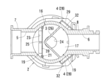
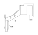
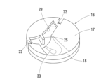
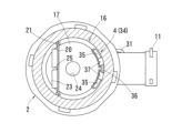
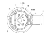
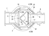
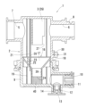
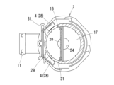
- FIG. 1 A sectional view showing a first embodiment of a foreign matter removal device according to the present invention Cross-sectional view along line II-II in Figure 1 A perspective view showing the magnet and magnet holder of the foreign matter removal device shown in FIG. A sectional view showing a first modification of the foreign matter removal device shown in FIG. 1 A perspective view showing a partition member of the foreign matter removal device shown in FIG. 4 A sectional view showing a second modification of the foreign matter removal device shown in FIG. 1 Cross-sectional view along line VII-VII in Figure 6 Cross-sectional view along line VIII-VIII in Figure 6 A perspective view showing a partition member of the foreign matter removal device shown in FIG. 6 A sectional view showing a third modification of the foreign matter removal device shown in FIG.
- FIG. 14 A sectional view of main parts showing a third modification of the foreign matter removal device shown in FIG. 14 A sectional view showing a third embodiment of a foreign matter removal device according to the present invention
- Cross-sectional view along line XXIII-XXIII in FIG. 22 Cross-sectional view along line XXIV-XXIV in Figure 22
- This foreign matter removal device 1 is a device for removing foreign matter in a heating circuit in which hot water circulates in a heating device that uses fluid hot water (heating water) as a heat medium.
- the main components are a main body part 2, a deflecting member 3, and a foreign matter removing part 4.
- the arrows shown in FIG. 1 indicate fluid flow paths, and the difference in thickness roughly corresponds to the difference in flow rate.
- the main body part 2 is a cylindrical member with a fluid inlet 5 and an outlet 6 formed at the upper end and an open lower part.
- the inlet 5 and the outlet 6 are located above the center of the cylinder in the height direction and on opposite sides in the circumferential direction of the cylinder, and the inlet 5 and the outlet 6 are formed at approximately the same height of the cylinder. There is.
- the inner diameter of the inlet 5 is slightly larger than the inner diameter of the outlet 6.
- An inlet pipe connection part 7 is formed at the inlet port 5, and an outlet pipe connection part 8 is formed at the outlet port 6, so that they can be connected to other pipes constituting the heating circuit.
- the vertical positional relationship between the inlet 5 and the outlet 6 is not limited to this embodiment, and may be changed.
- the shape of the main body portion 2 is not limited to a cylindrical shape, and may be appropriately changed to an elliptical cylinder shape, a rectangular cylinder shape, etc.
- a collection part 9 is provided which has a bottomed cylindrical shape with an open top and has approximately the same diameter as the main body part 2.
- the main body part 2 and the collection part 9 are connected by a so-called snap lock mechanism in which both are inserted into each other in the axial direction and then rotated by a predetermined small angle in the circumferential direction to be in a locked state.
- a cock valve 10 in which an insertion hole for a hexagonal wrench is formed is attached to the collection part 9 by a pin fastener 11. Further, a plug 13 is fixed to a drain port 12 formed in the lower part of the collection part 9 with a pin fastener 14.
- the cock valve 10 and the plug 13 are provided on the wall surface of the collection section 9 on the outlet 6 side.
- a resin material is used as the material for the main body part 2 and the collection part 9, but it is possible that other materials made of non-magnetic material can be used.
- An inclined surface 15 is formed on the bottom surface of the collection portion 9 and is inclined downward toward the cock valve 10 side. Note that the inclined surface 15 may be omitted by optimizing the arrangement of the cock valve 10 and the like.
- a partition member 16 is provided between the main body portion 2 and the collection portion 9 to partition the two.
- the partition member 16 has a cone portion 17 whose diameter decreases downward, and a cylindrical portion 18 extending downward in the axial direction from the upper end of the cone portion 17.
- Ribs 19 are formed on the inner surface of the main body portion 2, and when the ribs 19 come into contact with the partition member 16, the partition member 16 is positioned in the vertical direction.
- a rib 21 for holding a filter 20 (to be described later) is formed on the inner wall of the main body 2. By fitting the rib 21 into a slit 22 formed in the partition member 16, the partition member 16 Circumferential positioning is performed.
- a rectangular through hole 23 is formed near the inlet 5 of the cone portion 17, and a circular through hole 24 is formed in the center of the cone portion 17, so as to communicate between the main body portion 2 and the collection portion 9. ing.
- a projecting piece 25 is formed on one upstream side of the rectangular through hole 23 and projects toward one downstream side.
- the rectangular through hole 23, the circular through hole 24, and the drain port 12 are lined up in this order in one direction. Since the rectangular through hole 23 is eccentric in one direction with respect to the circular through hole 24 formed in the center of the cone portion 17, the fluid discharges from both the rectangular and circular through holes 23 and 24. , when the cock valve 10 and the stopper 13 are opened, a flow toward the drain port 12 is generated within the collecting section 9.
- the deflection member 3 branches the fluid flowing in from the inlet 5 toward the inner wall of the main body 2 and deflects the flow direction in the vertical direction so that the branched fluid flows along the inner wall of the main body 2.
- This is a V-shaped plate 26 that extends in the vertical direction and has a V-shape in plan view.
- This V-shaped plate 26 has a lower end that is closer to the inner bottom surface of the inlet 5 and the outlet 6 so that the fluid flowing in from the inlet 5 does not flow horizontally and directly flows out from the outlet 6. It is also extended to the bottom. Both ends of the V-shaped plate 26 are in contact with the inner wall of the main body 2.
- This V-shaped plate 26 divides the cylindrical interior of the main body 2 into an inlet 5 side and an outlet 6 side in plan view.
- a notch 27 is formed at the lower end of the V-shaped plate 26 by cutting out both ends of the V-shape.
- the magnet 28 as the foreign matter removing section 4 is provided on the outer wall of the main body section 2 so as to follow the flow of the fluid deflected by the deflection member 3 (V-shaped plate 26). More specifically, two magnets 28 are provided in pairs below the lower end of the V-shaped plate 26 and on the downstream side of the filter 20, which will be described later.
- the mounting position of the magnet 28 on the outer wall of the main body 2 can be determined as appropriate, but it is preferable to install it between the side of the main body 2 (the middle position between the inlet 5 and the outlet 6) and the side of the outlet 6. preferable. Note that depending on the arrangement of the filter 20, it may be possible to provide a configuration in which the magnet 28 is provided upstream of the filter 20. As shown in FIG.
- the magnet 28 is a flat neodymium magnet held by a magnet holder 29 by suction, and is sandwiched between ribs 30 formed on the outer wall of the main body 2 in surface contact with the pin fastener 31.
- Fixed by A flat portion 32 having a flat surface is formed at the portion of the main body portion 2 that is in contact with the magnet 28 . Thereby, the outer wall (flat portion 32) of the main body portion 2 and the magnet 28 are in surface contact.
- a filter 20 is arranged in the flow path of the fluid flowing through the main body part 2.
- the filter 20 is a wire mesh in the shape of a substantially rectangular flat plate, and its both ends are sandwiched between ribs 21 formed on the inner wall of the main body part 2, and its lower end is a rectangular wire mesh formed in the cone part 17 of the partition member 16.
- the filter 20 is arranged so that the fluid is branched into a flow path passing through the filter 20 and a flow path flowing downward along the surface of the filter 20.
- the fluid containing foreign matter flows into the main body 2 through the inlet 5 and mainly passes through the filter 20. Since a V-shaped plate 26 is provided at the rear of the filter 20, the fluid flowing from the inlet 5 branches left and right toward the inner wall of the main body 2 and is deflected downward. At this time, among the foreign substances contained in the fluid, non-magnetic substances such as rust are collected near the surface of the filter 20 by the flow component passing through the filter 20, and are successively dropped by the flow component moving downward along the surface of the filter 20. do.
- This foreign material passes through a rectangular through hole 23 formed in the cone portion 17 of the partition member 16 and is collected by the collection portion 9 . According to this configuration, foreign matter can be collected while preventing clogging of the filter 20 without stopping the fluid flow midway.
- the sizes of the rectangular through hole 23 and the circular through hole 24 formed in the cone portion 17 are set to appropriate sizes to prevent the fluid from flowing into the collection portion 9 side as much as possible during water flow.
- the width of the rectangular through hole 23 is 1.8 to 12 mm, preferably 3 to 9 mm
- the diameter of the circular through hole 24 is 5 to 30 mm, preferably 8 to 20 mm.
- the flow of the main body part 2 does not affect the collection part 9, so that the foreign matter collected by the collection part 9 ( There is no risk of non-magnetic substances flying up during water flow. Therefore, foreign matter in the fluid can be efficiently removed.
- the notch 27 since the notch 27 is formed at the lower end of the V-shaped plate 26, this notch 27 functions as a fluid bypass path and reduces the flow velocity near the lower end of the deflection member 3 to a certain extent.
- the flow in the vicinity of the magnet 28 can be optimized by, for example, Therefore, especially when the flow rate of the fluid is large, it is possible to prevent the magnetic material attracted to the magnet 28 from peeling off due to the fluid, and it is possible to further improve the adsorption efficiency of the magnetic material.
- the cutout portion 27 may be omitted by optimizing the fluid flow direction and the position of the magnet 28 as a result of changing the design of each member.
- the magnetic material such as iron powder that has been attracted to the magnet 28 falls off, and the circular shape formed on the cone 17 of the partition member 16 is removed. It passes through the through hole 24 and is collected by the collection section 9 . Then, when the stopper 13 provided at the drain port 12 is removed and the cock valve 10 provided at the collection section 9 is opened while the water flow is stopped, foreign matter (magnetic material, non-magnetic material, etc.) collected in the collection section 9 is removed. body) is discharged through the drain port 12 together with the fluid in the main body part 2.
- the filter 20 is arranged so that the fluid is branched into a flow path passing through the filter 20 and a flow path flowing downward along the surface of the filter 20. 20 may be provided so that the entire amount of fluid passes through this filter 20.
- FIGS. 4 and 5 A first modification of the foreign matter removal device 1 according to the first embodiment is shown in FIGS. 4 and 5.
- This first modification has the same basic configuration as the first embodiment described above, but differs in the configuration of the partition member 16. That is, in the partition member 16 according to the first embodiment, a rectangular through hole 23 is formed near the inlet 5 of the cone portion 17, and a circular through hole 24 is formed in the center of the cone portion 17. On the other hand, in the partition member 16 according to the first modification, only the rectangular through hole 23 is formed near the inlet 5 of the cone portion 17, and the rectangular through hole 23 is formed in the center of the cone portion 17. A sloped portion 33 is formed that slopes downward toward the top.
- the non-magnetic material is not removed by the filter 20.
- the magnetic material once passes through the filter 20 and is attracted by the magnet 28, but when the magnet 28 is removed from the main body 2 along with the magnet holder 29 after the water flow is stopped, the magnetic material that was attracted to the magnet 28 is removed. falls off, is guided by the slope 33 formed in the cone portion 17 of the partition member 16, slides down toward the filter 20, passes through the filter 20 in the opposite direction, and is collected through the rectangular through hole 23. 9 (see arrow f in FIG. 4).
- a second modification of the foreign matter removal device 1 according to the first embodiment will be explained using FIGS. 6 to 9.
- a resistance member 34 that provides flow resistance to the fluid along the inner wall of the main body portion 2 is adopted as the foreign matter removal unit 4 instead of the magnet 28, and the resistance member 34 provides resistance to the fluid. It is configured so that foreign matter inside falls downward.
- This resistance member 34 has an intake port 35 that takes in the fluid flowing along the inner wall of the main body portion 2, and an abutment wall 36 that the fluid taken in from the intake port 35 comes into contact with.
- a drop port 37 is formed in the cone portion 17 of the partition member 16 to allow foreign matter in the fluid subjected to flow resistance by the contact wall 36 to fall downward.
- the drop port 37 is a through hole that communicates with the collection section 9 .
- FIGS. 10 and 11 A third modification of the foreign matter removal device 1 according to the first embodiment is shown in FIGS. 10 and 11.
- the basic configuration of this third modification is the same as that of the first embodiment, but from the upper end of the main body part 2 to the cone part 17 is located closer to the outlet 6 than the circular through hole 24 formed in the cone part 17.
- the difference is that an auxiliary filter 38 is provided.
- This auxiliary filter 38 is made of a flat wire mesh, and is configured such that the entire amount of fluid flowing from the inlet 5 to the outlet 6 passes through the auxiliary filter 38.
- the auxiliary filter 38 By providing the auxiliary filter 38 in this manner, even if the foreign matter collected by the collection section 9 should fly up to the main body section 2 side due to the flow of fluid, the foreign matter that has flown up will be captured by the auxiliary filter 38. Therefore, the foreign matter can be prevented from flowing out from the outlet 5. Further, the auxiliary filter 38 is slightly spaced apart from the outlet 6, and a sufficient water flow cross-sectional area (filter area) for the fluid passing through the auxiliary filter 38 can be ensured. Therefore, even if a large amount of foreign matter is contained in the fluid, clogging of the auxiliary filter 38 can be prevented as much as possible.
- the filter 20 (including the auxiliary filter 38) becomes clogged during water flow, water flow resistance increases and the current value, voltage value, etc. of the pump are affected. Therefore, it is possible to detect fluctuations in water pressure, pump current values, voltage values, etc. using various sensors, and control the water flow to be cut off and water flowed again when it is determined that the filter 20 is clogged. is preferred.
- FIG. 12 A fourth modification of the foreign matter removal device 1 according to the first embodiment is shown in FIG. 12.
- This fourth modification also has the same basic configuration as the first embodiment, but an extension cylindrical part 39 is connected to the lower end of the cone part 17, and the inner bottom surface of the collection part 9 is attached to this extension cylindrical part 39.
- a cylindrical filter 40 is provided.
- the lower end of the extension tube portion 39 corresponds to the through hole 24 in the first embodiment.
- the cylindrical filter 40 is made of a wire mesh formed in a cylindrical shape, and is configured such that the entire amount of fluid flowing from the inlet 5 to the outlet 6 passes through the filter 20 or the cylindrical filter 40.
- the cylindrical filter 40 When the cylindrical filter 40 is provided in this way, the water flows into the collection part 9 through the through hole 23 formed in the cone part 17, and further flows into the main body part 2 through the through hole 24 formed in the extension cylindrical part 39. Even if foreign matter collected by the collecting section 9 is thrown up by the returning flow, the cylindrical filter 40 can prevent the foreign matter from flowing into the main body section 2.
- FIG. 13 A fifth modification of the foreign matter removal device 1 according to the first embodiment is shown in FIG. 13.
- the filter 20 is not provided, and foreign matter is removed only by the auxiliary filter 38, and the side closer to the inlet than the circular through hole 24 in the center of the cone part 17 is
- the configuration differs from that of the second modification in that a through hole 41 is formed in the second modification.
- a through hole 41 is formed in the second modification.
- the stopper 13 provided in the drain port 12 is removed and the cock valve 10 provided in the collection portion 9 is opened while water is not flowing, water flows through the circular through hole 24 into the main body portion 2.
- the fluid is also discharged from the through hole 41 formed on the side closer to the inlet 5 (see arrow f in FIG. 13).
- this through hole 41 is not an essential component and may be omitted as appropriate.
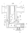
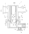
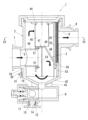
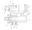
- FIGS. 14 to 16 A second embodiment of the foreign matter removal device 1 according to the present invention is shown in FIGS. 14 to 16. Similar to the first embodiment, this foreign matter removing device 1 includes a main body portion 2, a deflecting member 3, and a foreign matter removing section 4 as main components.
- the main body 2 is a cylindrical member with an open top and an inlet 5 and an outlet 6 for fluid.
- the outflow port 6 is formed above the inflow port 5 and on opposite sides of the cylinder in the circumferential direction.
- the inner diameter of the inlet 5 is slightly larger than the inner diameter of the outlet 6.
- An inlet pipe connection part 7 is formed at the inlet port 5, and an outlet pipe connection part 8 is formed at the outlet port 6, so that they can be connected to other pipes constituting the heating circuit.
- the vertical positional relationship between the inlet 5 and the outlet 6 is not limited to this embodiment, and may be reversed.
- the shape of the main body portion 2 is not limited to a cylindrical shape, and may be appropriately changed to an elliptical cylinder shape, a rectangular cylinder shape, etc.
- the lower end side of the main body portion 2 is formed with a reduced diameter portion 42 that gradually reduces in diameter toward the bottom.
- a collection section 9 is provided at the lower part of the reduced diameter section 42 .
- the main body part 2 and the collection part 9 are connected by a thin tube part 43 formed in the reduced diameter part 42.
- This collecting section 9 is provided outside the flow range of the fluid flowing through the main body section 2, and has a function of temporarily collecting foreign matter in the fluid.
- a cock valve 10 with a handle is attached to the collection part 9 with a pin fastener 11. Further, a plug 13 is fixed to a drain port 12 formed in the lower part of the collection part 9 with a pin fastener 14.
- the stopcock 13 is removed from the drain port 12 and the cock valve 10 is opened, the fluid inside the main body 2 can be discharged together with the foreign matter collected by the collection section 9.
- the main body portion 2 and the collection portion 9 are integrally constructed, but they may also be constructed as separate parts. Further, in this embodiment, a resin material is used as the material for the main body part 2 and the collection part 9, but it is possible that other materials made of non-magnetic material can be used.
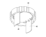
- a lid 44 is provided at the upper opening of the main body 2.
- a contact member 45 that can come into contact with the upper part of the deflection member 3 extends downward on the lower surface side of the lid 44.
- This contact member 45 has a curved shape obtained by cutting a portion of a cylinder, and is arranged along the inner wall of the main body portion 2 .
- This contact member 45 may always be in contact with the upper surface of the deflection member 3, but in this embodiment, there is a slight gap (about 0.5 mm) between the two due to the design, and the deflection member 3
- the deflection member 3 and the contact member 45 are configured to contact each other only when the deflection member 3 and the contact member 45 are displaced upward by the gap from the predetermined installation position.
- the deflection member 3 may bounce upward due to vibrations during transportation of the foreign object removal device 1 that has been assembled, or may be displaced upward due to the water pressure during water flow, and the deflection member 3 may be moved to a predetermined position. prevents it from shifting from its installed position.
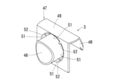
- the deflection member 3 has a short-circuit pipe 46 extending from the inlet 5 side toward a wall facing the inlet 5, and an area where the fluid mainly flows downward and an area where the fluid mainly flows upward. It has a deflection plate 47 that is largely divided into a flow area and a deflection plate 47 that deflects the fluid that has passed through the short-circuit pipe 46 downward. The fluid deflected by the deflection plate 47 turns at the lower end of the main body 2 (near the reduced diameter section 42), passes through the inlet 5, and heads upward.
- the deflecting plate 47 has an inclined part 48 that faces the opposing wall surface and is inclined downward toward the tip thereof, and a partition wall 49 that connects this inclined part 48 and the short-circuit pipe 46.
- a discharge gap 50 is formed between the opposing wall surface and the tip (sloped lower end) of the inclined portion 48, in which foreign matter falling off the filter 20 (described later) when the water flow is stopped is allowed to fall toward the collecting portion 9.
- the size of the discharge gap 50 is approximately 5 mm, but it can be changed as appropriate within the range of approximately 1 to 20 mm.
- the size of the discharge gap 50 can also be changed as appropriate depending on the diameter of the main body portion 2.
- the deflection member 3 (the shorting pipe 46 and the deflection plate 47) is integrally formed.
- a reflux passage 51 is provided at the outer peripheral edge of the short-circuiting pipe 46 on the outlet side to guide the fluid flowing upward along the outer peripheral edge of the short-circuiting pipe 46 and the partition wall 49 of the deflection plate 47 to the outlet side of the short-circuiting pipe 46 .
- Reinforcing ribs 52 are provided in the reflux passage 51 at predetermined intervals to ensure rigidity between the short-circuit pipe 46 and the partition wall 49.
- the integrated deflection member 3 is positioned at a predetermined mounting position by abutting against a rib 53 formed inside the main body portion 2 .
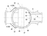
- the magnet 28 as the foreign matter removing section 4 is provided on the outer wall of the main body section 2 so as to follow the flow of the fluid deflected by the deflection member 3 (the short-circuit tube 46 and the deflection plate 47). More specifically, two magnets 28 are provided in pairs at the side portions below the height of the short-circuiting tube 46 .
- the mounting position of the magnet 28 on the outer wall of the main body 2 can be determined as appropriate, but it is preferable to install it between the side of the inlet 5 and the side of the main body 2 (midway between the inlet 5 and the outlet 6). preferable.
- a flat neodymium magnet is used as the magnet 28.
- This magnet 28 is magnetically attracted to a magnet holder 29 made of a magnetic steel material, and this magnet holder 29 is sandwiched between ribs 30 formed on the outer wall of the main body 2 in a surface contact state, and is held by a pin fastener 31.
- a flat portion 32 having a flat surface is formed at the portion of the main body portion 2 that is in contact with the magnet 28 . Thereby, the outer wall (flat portion) of the main body portion 2 and the magnet 28 are in surface contact.
- a filter 20 is arranged immediately in front of the outlet 6 of the main body 2.
- This filter 20 is positioned at a predetermined mounting position by coming into contact with a rib 53 formed inside the main body portion 2 .
- a wire mesh is used as the filter 20.
- This filter 20 has a curved shape obtained by cutting a part of a cylinder, and is placed over the inner wall of the main body 2 just in front of the outlet 6 so that the entire amount of fluid passes through the filter 20. .
- the upper end of this filter 20 is located near the lower surface of the lid 44, and the lower end is located approximately several mm above the lower end of the inclined portion 48 of the deflection plate 47.
- the fluid containing foreign matter flows into the main body 2 through the short-circuit pipe 46 of the deflection member 3 provided at the inlet 5.
- This fluid is given straightness by the straight short-circuit pipe 46 and flows toward the wall surface facing the inlet 5 (rightward in FIG. 14). Then, it is deflected downward by the inclined portion 48 formed on the deflecting member 3, turns at the lower end of the main body 2, passes through the inlet 5 side, and heads upward. Since the foreign matter has a higher specific gravity than the fluid, when the fluid is deflected within the main body 2, an inertial force acts on the foreign matter.
- this foreign material is extremely small, for example, iron powder is on the order of micrometers, it flows smoothly along the inner wall of the main body 2 without stagnation in the middle of the flow. As the size of the foreign object increases, the inertial force increases, making it easier to flow along the inner wall.
- the deflection plate 47 of the deflection member 3 is formed with an inclined portion 48 that slopes downward toward the tip thereof, thereby smoothly deflecting the fluid downward and reducing water flow resistance.
- this inclined portion 48 is not formed.
- magnetic substances such as iron powder are attracted by the magnetic force of the magnet 28 provided on the outer wall of the main body 2.
- This foreign material made of magnetic material flows along the inner wall surface of the main body part 2 along with the fluid, but if the flow velocity of the fluid is high, it is difficult to be attracted to the magnet 28, and even if it is once attracted, it will peel off and be washed away. There is a risk. Therefore, it is preferable to restrict the upper limit of the amount of water flowing into the main body 2 (eg, 10 L/min or less) so that the foreign matter can be stably attracted to the magnet 28.
- This magnet 28 is attracted and held by a magnet holder 29 made of a magnetic material. Therefore, compared to a case where a pocket is formed in the magnet holder 29 and the magnet 28 is housed and held in the pocket, the magnet 28 is easily exposed from the magnet holder 29. Further, since a flat part 32 is formed on the outer wall of the main body part 2, and the magnet 28 is in surface contact with this flat part 32, the magnetic force of the magnet 28 tends to act directly on the inside of the main part 2, and the magnetic material It is possible to effectively adsorb foreign matter consisting of. Further, since the magnet holder 29 is made of a magnetic material, the magnet holder 29 acts as a yoke, and can prevent the lines of magnetic force from expanding outward.
- the magnetic flux density inside the main body portion 2 increases, and foreign matter made of magnetic material can be attracted more efficiently.
- the magnet holder 29 is stably held by a total of three planes, that is, a rib 30 formed on the outer wall of the main body part 2 and two flat parts, it is possible to prevent the magnet from shifting.
- the magnet 29 is provided at the side portion below the height position of the short circuit pipe 46, but the position is not particularly limited, and as long as it is below the height position of the short circuit pipe 46, In some cases, it can be provided at any position along the circumferential direction of the main body part 2. Further, it may be possible to provide the lower surface of the reduced diameter portion 42 formed on the lower end side of the main body portion 2 in some cases.
- the height of the short-circuit pipe 46 is the same as that of the short-circuit pipe 46 because the width of the flow path becomes narrower due to the short-circuit pipe 46 itself, increasing the flow velocity. In either case, the adsorption efficiency may decrease because they tend to separate.
- the stiffness between the short-circuit pipe 10 and the partition wall 49 is ensured by providing reinforcing ribs 52 at predetermined intervals in the reflux passage 51.
- the effect of improving the rigidity of the reinforcing rib 52 can be further enhanced. Note that this reflux passage 51 may be omitted in some cases.
- the fluid flowing upward through the short-circuit pipe 46 is further deflected in the horizontal direction (rightward in FIG. 14) by the lid 44 provided at the upper opening of the main body 2, passes through the filter 20, and exits from the outlet 6. leak.
- non-magnetic substances such as rust are once captured by the filter 20.
- foreign matter made of non-magnetic material falls off from the filter 20, passes through the discharge gap 50 and the thin tube section 43, and is collected by the collection section 9.
- the diameter (inner diameter) of the thin tube portion 43 is set to an appropriate diameter to prevent fluid from flowing into the collecting portion 9 side as much as possible during water flow.
- the diameter of the thin tube portion 43 can be in the range of 5 to 30 mm, preferably 8 to 20 mm. In this way, by connecting the main body part 2 and the collection part 9 with the thin tube part 43, the flow of the main body part 2 does not affect the collection part 9, so that it does not fall off from the filter 20 when water flow is stopped. There is no fear that the foreign matter (non-magnetic material) collected in the collecting portion 9 will fly up when water is recirculated. Therefore, foreign matter in the fluid can be efficiently removed.
- the fluid in the discharge gap 50 is drawn downward by the ejector effect caused by the flow of fluid that flows in from the inlet 5 and is deflected downward by the slope portion 48 . Therefore, it is possible to prevent a short circuit in which the fluid flowing in from the inlet 5 flows upward through the discharge gap 50 and directly flows out from the outlet 6.
- the magnetic material such as iron powder that has been attracted to the magnet 28 falls off, passes through the thin tube section 43 and is temporarily collected by the collection section 9. is collected by.
- the stopper 13 provided at the drain port 12 is removed and the cock valve 10 provided in the collection section 9 is opened while water flow is stopped, foreign substances (magnetic materials, non-magnetic materials) collected in the collection section 9 are removed. is discharged through the drain port 12 together with the fluid in the main body portion 2.
- the stopper 13 provided at the drain port 12 is removed and the cock valve 10 provided in the collection section 9 is opened while water flow is stopped, foreign substances (magnetic materials, non-magnetic materials) collected in the collection section 9 are removed. is discharged through the drain port 12 together with the fluid in the main body portion 2.
- an inclined surface 15 on the bottom surface of the collection part 9 that slopes downward toward the cock valve 10 (see FIG. 1), foreign matter can be smoothly drained together with the fluid. It can be discharged through the port 12.
- water flow intermittent control is performed in which water flow is temporarily cut off after a predetermined time (e.g., 5 minutes) has elapsed since the start of water flow, and water flow is restarted when a predetermined time (e.g., 5 minutes) has elapsed since the cutoff. You can also do this.
- This intermittent water flow control cuts off water flow when a certain amount of foreign matter is captured by the filter 20 after a predetermined period of time has elapsed from the start of water flow, and the foreign matter captured by the filter 20 is dropped into the collection unit 9. let As the foreign matter falls off, the filter 20 is unclogged, and the amount of water flowing through the filter 20 at the time of water flow again can be restored.
- This water flow intermittent control can be performed at an appropriate timing, such as when the water in the pipes is drained as described above.
- this timing for example, when installing a new heating appliance, it is performed every time the heating appliance is started, within a predetermined time (for example, within 10 hours) from the first operation, or until the operation restarts after a prescribed number of starts (for example, the 10th time). It is also possible to define various control rules such as: Further, the blocking of water flow and the re-flow of water can be repeated multiple times until a certain amount of foreign matter in the iron pipe is removed.
- the above-mentioned predetermined time period from when the water flow is cut off to when the water flow is restarted can be changed as appropriate in consideration of the amount of foreign matter contained in the water, the ease with which the foreign matter falls off from the filter 20, and the like.
- a thin tube portion 43 is formed at the axial center of the main body portion 2, and the inner bottom surface of the reduced diameter portion 42 has a mortar shape that is evenly inclined in the circumferential direction with respect to the thin tube portion 43.
- the inner bottom surface of the reduced diameter part 42 on the side where the filter 20 is provided is It is also possible to adopt a configuration in which a stepped portion 54 with a raised inner bottom surface is formed. In this way, foreign matter that falls off the filter 20 when the water flow is stopped and accumulates on the inner bottom surface of the reduced diameter portion 42 (portion A indicated by a broken line in FIG. 19) without reaching the collection portion 9 will be removed when the water flow is resumed. The particles are guided downward by the stepped portion 54, pass through the thin tube portion 43, and are smoothly collected in the collection portion 9. Therefore, it is possible to prevent the accumulated foreign matter from being swept up by the fluid when the water flow is resumed.
- a second modification of the second embodiment may have a configuration in which the thin tube portion 43 is offset from the center of the main body portion 2 toward the wall surface side.
- the thin tube portion 43 can be provided offset from the center of the main body portion 2 toward the filter 20 side. In this way, foreign matter made of a non-magnetic material that falls through the discharge gap 50 when the water flow is stopped can be smoothly guided to the collection section 9 through the thin tube section 43.
- a plurality of thin tube portions 43 may be provided so as to be offset from the center portion of the main body portion 2 toward the filter 20 side and the magnet 28 side. You can also do it.
- the thin tube portion 43 removes both non-magnetic foreign matter that fell off from the filter 20 when water flow was stopped and magnetic foreign matter that fell off the inner wall of the main body 2 when the magnet 28 was removed. can be smoothly guided to the collecting section 9.
- the number of thin tube portions 43 is not limited to two, and may be increased as necessary, for example, by providing two each on the magnet 28 side and the filter 20 side.
- the arrangement of the collecting section 9, cock valve 10, and drain port 12 is not limited to the arrangement shown in FIG. 14, and the collecting section 9, cock valve 10, and drain port 12 may be arranged vertically.
- the opening direction of the cock valve 10 is rotated by 90 degrees with respect to the configuration shown in FIG. It is also possible to use a jig to take out the clogged foreign matter from the drain port 12 side.
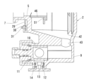
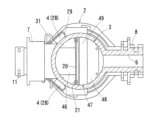
- FIGS. 22 to 24 A third embodiment of the foreign matter removal device 1 according to the present invention is shown in FIGS. 22 to 24.
- This foreign matter removal device 1 is based on the foreign matter removal device 1 according to the second embodiment, and employs the configuration of the filter 20 according to the first embodiment.
- the foreign matter removal device 1 according to the third embodiment mainly includes the main body 2, the deflection member 3 (the short-circuit tube 46, the deflection plate 47), and the foreign matter removal section 4 (the magnet 28). It is considered as a component.
- the configurations of the main body portion 2, the deflection member 3, and the foreign matter removal portion 4 are the same as those in the first embodiment or the second embodiment, and therefore, redundant explanation will be omitted.
- the foreign matter removal device 1 has a partition member 16 similar to that of the first embodiment that partitions between the main body 2 and the collection section 9, but a circular partition member 16 formed on the cone section 17
- the second embodiment is different in that the through hole 24 functions as both the rectangular through hole 23 and the circular through hole 24 in the first embodiment. Note that, as shown in FIG. 24, only a circular through hole 24 is formed in the cone portion 17, but as long as the flow of the main body portion 2 does not affect the collection portion 9, other holes may be formed in the cone portion 17. It is also possible to form a through hole.
- the foreign matter removal device 1 has a structure in which the filter 20 is arranged so that the fluid is branched into a flow path passing through the filter 20 and a flow path flowing downward along the surface of the filter 20.
- This is common to the first embodiment in that the filter 20 straddles the circular through hole 24 formed in the cone portion 17 in a state that is slightly biased toward the inlet 5 side from the center of the circular through hole 24. There is a difference.
- the filter 20 has both ends sandwiched between ribs 21 formed on the inner wall of the main body 2, and a pair of lower ends formed at the inner edge of a circular through hole 24 formed in the cone portion 17 of the partition member 16. It is positioned at a predetermined mounting position by being inserted into a slit (not shown).
- the fluid containing foreign matter flows into the main body 2 through the short-circuit pipe 46 of the deflection member 3 provided at the inlet 5.
- This fluid is given straightness by the straight short-circuit pipe 46 and flows toward the wall surface facing the inlet 5 (toward the right in FIG. 22). Then, it is deflected downward by the inclined portion 48 formed on the deflecting member 3, turns at the lower end of the main body 2, and heads toward the inlet 5 side.
- non-magnetic substances such as rust are collected near the surface of the filter 20 by the flow component passing through the filter 20, and fall by the flow component moving downward along the surface of the filter 20. .
- the size of the circular through hole 24 formed in the cone part 17 is set to an appropriate size to prevent the fluid from flowing into the collection part 9 side as much as possible during water flow.
- the diameter of the circular through hole 24 is in the range of 5 to 30 mm, preferably 8 to 20 mm.
- the partition member 16 is provided between the main body part 2 and the collection part 9, but as in the second embodiment, the main body part 2 and the collection part 9 are connected by the thin tube part 43. It is also possible that a connected configuration can be provided.
- a neodymium magnet was used as the magnet 28, but an electromagnet may also be used. In this way, by cutting off the power to the electromagnet, the magnetic material attracted to the electromagnet can be easily separated and collected by the collecting section 9, and maintenance work can be performed smoothly. .
- the magnet 28 captures the magnetic material and the filter 20 captures the non-magnetic material.
- the filter 20 can be omitted.
- the magnet 28 can be omitted if only the non-magnetic material needs to be captured, or if the magnetic material is of a size that can be sufficiently captured by the filter 20.
Landscapes
- Chemical & Material Sciences (AREA)
- Chemical Kinetics & Catalysis (AREA)
- Engineering & Computer Science (AREA)
- Water Supply & Treatment (AREA)
- Filtration Of Liquid (AREA)
- Details Of Valves (AREA)
- Auxiliary Devices For Machine Tools (AREA)
Priority Applications (3)
| Application Number | Priority Date | Filing Date | Title |
|---|---|---|---|
| JP2023509822A JP7437103B1 (ja) | 2022-06-28 | 2022-06-28 | 異物除去装置 |
| PCT/JP2022/025783 WO2024004038A1 (ja) | 2022-06-28 | 2022-06-28 | 異物除去装置 |
| EP22936732.1A EP4324541A4 (en) | 2022-06-28 | 2022-06-28 | DEVICE FOR REMOVING FOREIGN SUBSTANCES |
Applications Claiming Priority (1)
| Application Number | Priority Date | Filing Date | Title |
|---|---|---|---|
| PCT/JP2022/025783 WO2024004038A1 (ja) | 2022-06-28 | 2022-06-28 | 異物除去装置 |
Publications (1)
| Publication Number | Publication Date |
|---|---|
| WO2024004038A1 true WO2024004038A1 (ja) | 2024-01-04 |
Family
ID=89381788
Family Applications (1)
| Application Number | Title | Priority Date | Filing Date |
|---|---|---|---|
| PCT/JP2022/025783 Ceased WO2024004038A1 (ja) | 2022-06-28 | 2022-06-28 | 異物除去装置 |
Country Status (3)
| Country | Link |
|---|---|
| EP (1) | EP4324541A4 (cg-RX-API-DMAC7.html) |
| JP (1) | JP7437103B1 (cg-RX-API-DMAC7.html) |
| WO (1) | WO2024004038A1 (cg-RX-API-DMAC7.html) |
Families Citing this family (1)
| Publication number | Priority date | Publication date | Assignee | Title |
|---|---|---|---|---|
| GB2703720A (en) * | 2025-01-08 | 2026-08-12 | Adey Holdings 2008 Ltd | Separator device |
Citations (9)
| Publication number | Priority date | Publication date | Assignee | Title |
|---|---|---|---|---|
| WO1996004062A1 (en) * | 1994-08-03 | 1996-02-15 | Heco International A/S | A filter, in particular a magnet filter for continuous service |
| US20140367341A1 (en) | 2012-02-27 | 2014-12-18 | Hitachi, Ltd. | Coagulant, coagulation method, and water treatment apparatus |
| CN105508624A (zh) * | 2015-11-13 | 2016-04-20 | 广东联塑科技实业有限公司 | 一种软化水质过滤阀 |
| EP3159313A1 (en) | 2015-10-21 | 2017-04-26 | R.B.M. S.p.A. | Magnetic filter for treating a fluid in a pipe, in particular of a water network |
| WO2017216669A1 (en) * | 2016-06-14 | 2017-12-21 | Giacomini S.P.A. | Filter assembly for heating plants and the like |
| WO2018207083A1 (en) | 2017-05-09 | 2018-11-15 | Caleffi S.P.A. | Magnetic sludge separator for heating plants |
| EP3449995A1 (en) * | 2017-07-25 | 2019-03-06 | Euroacque S.r.l. | A sludge filter device |
| US20200086247A1 (en) * | 2016-07-22 | 2020-03-19 | Spiro Enterprises B.V. | Liquid treatment device |
| JP2022103686A (ja) * | 2020-12-28 | 2022-07-08 | 株式会社ワイ・ジェー・エス. | 異物除去装置 |
Family Cites Families (4)
| Publication number | Priority date | Publication date | Assignee | Title |
|---|---|---|---|---|
| US4585553A (en) * | 1982-11-24 | 1986-04-29 | Dai Nippon Insatsu Kabushiki Kaisha | Apparatus for the removal of solid particles from printing ink or other liquids |
| ITMI20111687A1 (it) * | 2011-09-19 | 2013-03-20 | Caleffi Spa | Separatore magnetico di particelle per impianti termici |
| WO2020044645A1 (ja) * | 2018-08-29 | 2020-03-05 | 株式会社前田シェルサービス | 磁気フィルタ装置 |
| EP3849686B1 (en) * | 2018-09-10 | 2024-02-21 | I.V.A.R. S.P.A. | Device and method for filtering a fluid circulating in a plumbing and heating system |
-
2022
- 2022-06-28 EP EP22936732.1A patent/EP4324541A4/en active Pending
- 2022-06-28 WO PCT/JP2022/025783 patent/WO2024004038A1/ja not_active Ceased
- 2022-06-28 JP JP2023509822A patent/JP7437103B1/ja active Active
Patent Citations (9)
| Publication number | Priority date | Publication date | Assignee | Title |
|---|---|---|---|---|
| WO1996004062A1 (en) * | 1994-08-03 | 1996-02-15 | Heco International A/S | A filter, in particular a magnet filter for continuous service |
| US20140367341A1 (en) | 2012-02-27 | 2014-12-18 | Hitachi, Ltd. | Coagulant, coagulation method, and water treatment apparatus |
| EP3159313A1 (en) | 2015-10-21 | 2017-04-26 | R.B.M. S.p.A. | Magnetic filter for treating a fluid in a pipe, in particular of a water network |
| CN105508624A (zh) * | 2015-11-13 | 2016-04-20 | 广东联塑科技实业有限公司 | 一种软化水质过滤阀 |
| WO2017216669A1 (en) * | 2016-06-14 | 2017-12-21 | Giacomini S.P.A. | Filter assembly for heating plants and the like |
| US20200086247A1 (en) * | 2016-07-22 | 2020-03-19 | Spiro Enterprises B.V. | Liquid treatment device |
| WO2018207083A1 (en) | 2017-05-09 | 2018-11-15 | Caleffi S.P.A. | Magnetic sludge separator for heating plants |
| EP3449995A1 (en) * | 2017-07-25 | 2019-03-06 | Euroacque S.r.l. | A sludge filter device |
| JP2022103686A (ja) * | 2020-12-28 | 2022-07-08 | 株式会社ワイ・ジェー・エス. | 異物除去装置 |
Non-Patent Citations (1)
| Title |
|---|
| See also references of EP4324541A4 |
Also Published As
| Publication number | Publication date |
|---|---|
| JP7437103B1 (ja) | 2024-02-22 |
| EP4324541A1 (en) | 2024-02-21 |
| JPWO2024004038A1 (cg-RX-API-DMAC7.html) | 2024-01-04 |
| EP4324541A4 (en) | 2025-04-16 |
Similar Documents
| Publication | Publication Date | Title |
|---|---|---|
| US7896169B2 (en) | Hydroclone based fluid filtration system | |
| EP2851126B1 (en) | Multi-cyclone collector | |
| US20150298139A1 (en) | Device For Separating Out Magnetizable Impurities From Flowing Fluids | |
| US7329342B2 (en) | Metallic particle trap bypass filter | |
| JP7437103B1 (ja) | 異物除去装置 | |
| GB2562772B (en) | Fluid treatment | |
| CN103826752A (zh) | 用于热力系统的磁性粒子分离器 | |
| JP2022103686A (ja) | 異物除去装置 | |
| KR20170092559A (ko) | 필터 장치, 유압 시스템 및 역세척 방법 | |
| EP3150266B1 (en) | Solid particles-fluids separator | |
| US11148079B2 (en) | Liquid treatment device | |
| CN1191499A (zh) | 磁性过滤装置 | |
| JP2024022670A (ja) | 異物除去装置 | |
| BR102013014357A2 (pt) | filtro fino para fluidos em fluxo e contentor de armazenamento para fluidos | |
| US5389252A (en) | Magnetic filter aid | |
| CN222287574U (zh) | 用于捕获和去除颗粒的设备 | |
| JP2003251542A (ja) | 切削液濾過装置 | |
| CN118341562A (zh) | 箱式除铁装置及碳捕集系统 | |
| CN208545254U (zh) | 污水处理系统 | |
| CN114632621A (zh) | 一种航空发动机油液、碎屑及废气分离器 | |
| CN224188002U (zh) | 混动箱润滑油滤清系统 | |
| RU2793244C2 (ru) | Фильтрующее устройство, в частности, для систем отопления | |
| KR200333645Y1 (ko) | 여과망을 설치한 자력 수처리기 | |
| KR101435143B1 (ko) | 사이클론 여과장치 | |
| JP2002172540A (ja) | 水溶性クーラント液再生装置 |
Legal Events
| Date | Code | Title | Description |
|---|---|---|---|
| ENP | Entry into the national phase |
Ref document number: 2023509822 Country of ref document: JP Kind code of ref document: A |
|
| ENP | Entry into the national phase |
Ref document number: 2022936732 Country of ref document: EP Effective date: 20231020 |
|
| NENP | Non-entry into the national phase |
Ref country code: DE |