WO2023286810A1 - 静止物情報利用装置、プログラム、静止物情報利用方法、車両システム、及び静止物情報利用システム - Google Patents
静止物情報利用装置、プログラム、静止物情報利用方法、車両システム、及び静止物情報利用システム Download PDFInfo
- Publication number
- WO2023286810A1 WO2023286810A1 PCT/JP2022/027588 JP2022027588W WO2023286810A1 WO 2023286810 A1 WO2023286810 A1 WO 2023286810A1 JP 2022027588 W JP2022027588 W JP 2022027588W WO 2023286810 A1 WO2023286810 A1 WO 2023286810A1
- Authority
- WO
- WIPO (PCT)
- Prior art keywords
- stationary object
- information
- vehicle
- object information
- image
- Prior art date
- Legal status (The legal status is an assumption and is not a legal conclusion. Google has not performed a legal analysis and makes no representation as to the accuracy of the status listed.)
- Ceased
Links
Images







Classifications
-
- B—PERFORMING OPERATIONS; TRANSPORTING
- B60—VEHICLES IN GENERAL
- B60Q—ARRANGEMENT OF SIGNALLING OR LIGHTING DEVICES, THE MOUNTING OR SUPPORTING THEREOF OR CIRCUITS THEREFOR, FOR VEHICLES IN GENERAL
- B60Q1/00—Arrangement of optical signalling or lighting devices, the mounting or supporting thereof or circuits therefor
- B60Q1/02—Arrangement of optical signalling or lighting devices, the mounting or supporting thereof or circuits therefor the devices being primarily intended to illuminate the way ahead or to illuminate other areas of way or environments
- B60Q1/04—Arrangement of optical signalling or lighting devices, the mounting or supporting thereof or circuits therefor the devices being primarily intended to illuminate the way ahead or to illuminate other areas of way or environments the devices being headlights
-
- B—PERFORMING OPERATIONS; TRANSPORTING
- B60—VEHICLES IN GENERAL
- B60Q—ARRANGEMENT OF SIGNALLING OR LIGHTING DEVICES, THE MOUNTING OR SUPPORTING THEREOF OR CIRCUITS THEREFOR, FOR VEHICLES IN GENERAL
- B60Q1/00—Arrangement of optical signalling or lighting devices, the mounting or supporting thereof or circuits therefor
- B60Q1/02—Arrangement of optical signalling or lighting devices, the mounting or supporting thereof or circuits therefor the devices being primarily intended to illuminate the way ahead or to illuminate other areas of way or environments
- B60Q1/04—Arrangement of optical signalling or lighting devices, the mounting or supporting thereof or circuits therefor the devices being primarily intended to illuminate the way ahead or to illuminate other areas of way or environments the devices being headlights
- B60Q1/14—Arrangement of optical signalling or lighting devices, the mounting or supporting thereof or circuits therefor the devices being primarily intended to illuminate the way ahead or to illuminate other areas of way or environments the devices being headlights having dimming means
-
- B—PERFORMING OPERATIONS; TRANSPORTING
- B60—VEHICLES IN GENERAL
- B60Q—ARRANGEMENT OF SIGNALLING OR LIGHTING DEVICES, THE MOUNTING OR SUPPORTING THEREOF OR CIRCUITS THEREFOR, FOR VEHICLES IN GENERAL
- B60Q1/00—Arrangement of optical signalling or lighting devices, the mounting or supporting thereof or circuits therefor
- B60Q1/02—Arrangement of optical signalling or lighting devices, the mounting or supporting thereof or circuits therefor the devices being primarily intended to illuminate the way ahead or to illuminate other areas of way or environments
- B60Q1/24—Arrangement of optical signalling or lighting devices, the mounting or supporting thereof or circuits therefor the devices being primarily intended to illuminate the way ahead or to illuminate other areas of way or environments for lighting other areas than only the way ahead
-
- G—PHYSICS
- G06—COMPUTING OR CALCULATING; COUNTING
- G06T—IMAGE DATA PROCESSING OR GENERATION, IN GENERAL
- G06T7/00—Image analysis
-
- G—PHYSICS
- G06—COMPUTING OR CALCULATING; COUNTING
- G06T—IMAGE DATA PROCESSING OR GENERATION, IN GENERAL
- G06T7/00—Image analysis
- G06T7/70—Determining position or orientation of objects or cameras
-
- G—PHYSICS
- G08—SIGNALLING
- G08G—TRAFFIC CONTROL SYSTEMS
- G08G1/00—Traffic control systems for road vehicles
- G08G1/01—Detecting movement of traffic to be counted or controlled
- G08G1/04—Detecting movement of traffic to be counted or controlled using optical or ultrasonic detectors
-
- G—PHYSICS
- G08—SIGNALLING
- G08G—TRAFFIC CONTROL SYSTEMS
- G08G1/00—Traffic control systems for road vehicles
- G08G1/09—Arrangements for giving variable traffic instructions
-
- G—PHYSICS
- G08—SIGNALLING
- G08G—TRAFFIC CONTROL SYSTEMS
- G08G1/00—Traffic control systems for road vehicles
- G08G1/16—Anti-collision systems
-
- G—PHYSICS
- G16—INFORMATION AND COMMUNICATION TECHNOLOGY [ICT] SPECIALLY ADAPTED FOR SPECIFIC APPLICATION FIELDS
- G16Y—INFORMATION AND COMMUNICATION TECHNOLOGY SPECIALLY ADAPTED FOR THE INTERNET OF THINGS [IoT]
- G16Y10/00—Economic sectors
- G16Y10/40—Transportation
-
- G—PHYSICS
- G16—INFORMATION AND COMMUNICATION TECHNOLOGY [ICT] SPECIALLY ADAPTED FOR SPECIFIC APPLICATION FIELDS
- G16Y—INFORMATION AND COMMUNICATION TECHNOLOGY SPECIALLY ADAPTED FOR THE INTERNET OF THINGS [IoT]
- G16Y40/00—IoT characterised by the purpose of the information processing
- G16Y40/10—Detection; Monitoring
-
- G—PHYSICS
- G16—INFORMATION AND COMMUNICATION TECHNOLOGY [ICT] SPECIALLY ADAPTED FOR SPECIFIC APPLICATION FIELDS
- G16Y—INFORMATION AND COMMUNICATION TECHNOLOGY SPECIALLY ADAPTED FOR THE INTERNET OF THINGS [IoT]
- G16Y40/00—IoT characterised by the purpose of the information processing
- G16Y40/30—Control
Definitions
- the present disclosure relates to a stationary object information utilization device, a program, a stationary object information utilization method, a vehicle system, and a stationary object information utilization system.
- Patent Literature 1 describes detecting a forward vehicle and controlling forward light distribution.
- ADB light distribution control is based on target information sent from the vehicle.
- Each target is detected by a specific algorithm based on the data acquired by sensors such as cameras. (excessive detection), or a target is detected even though it does not exist (false detection).
- stationary objects with high brightness such as street lights and signs on the road
- these stationary objects may be mistakenly recognized as the vehicle ahead.
- the headlamps of the vehicle ahead may be erroneously recognized as street lights. If information on stationary objects such as street lights and signs on the road can be collected, it is useful because it can be used to reduce the possibility of misrecognition as described above.
- the purpose of the present disclosure is to suitably utilize stationary object information of stationary objects such as street lights and signs on the road.
- a stationary object information utilization device includes: Still object image data corresponding to an image or a portion of the image in which one or more stationary objects selected from self-luminous bodies, signs, delineators, and guardrails exist, and the above calculated based on the stationary object image data
- Still object information including at least one of: still object position information indicating the position of the stationary object; a stationary object information acquiring unit that acquires the stationary object information and the imaging position information that are associated with each other from a database by wireless or wired communication; a stationary object detection unit that detects the stationary object based on the stationary object information and the imaging position information; Prepare.
- a program is A program comprising a processor and executed in a stationary object information utilization device mounted on a vehicle, The program causes the processor to: Still object image data corresponding to an image or a portion of the image in which one or more stationary objects selected from self-luminous bodies, signs, delineators, and guardrails exist, and the above calculated based on the stationary object image data
- Still object information including at least one of: still object position information indicating the position of the stationary object; a stationary object information acquiring step of acquiring the stationary object information and the imaging position information associated with each other from a database by wireless or wired communication; a stationary object detection step of detecting the stationary object based on the stationary object information and the imaging position information; to run.
- a stationary object information utilization method includes: A stationary object information utilization method comprising a processor and executed by a stationary object information utilization device mounted on a vehicle,
- the stationary object information utilization method comprises: Still object image data corresponding to an image or a portion of the image in which one or more stationary objects selected from self-luminous bodies, signs, delineators, and guardrails exist, and the above calculated based on the stationary object image data
- Still object information including at least one of: still object position information indicating the position of the stationary object; a stationary object information acquiring step of acquiring the stationary object information and the imaging position information associated with each other from a database by wireless or wired communication; a stationary object detection step of detecting the stationary object based on the stationary object information and the imaging position information; including running
- a stationary object information utilization device includes: Still object image data corresponding to an image or a portion of the image in which one or more stationary objects selected from self-luminous bodies, signs, delineators, and guardrails exist, and the above calculated based on the stationary object image data
- Still object information including at least one of: still object position information indicating the position of the stationary object; a stationary object information acquiring unit that acquires the stationary object information and the imaging position information that are associated with each other from a database by wireless or wired communication; a light distribution unit that controls light distribution of a vehicle headlight based on the stationary object information and the imaging position information; Prepare.
- a program comprising a processor and executed in a stationary object information utilization device mounted on a vehicle, The program causes the processor to: Still object image data corresponding to an image or a portion of the image in which one or more stationary objects selected from self-luminous bodies, signs, delineators, and guardrails exist, and the above calculated based on the stationary object image data
- Still object information including at least one of: still object position information indicating the position of the stationary object; a stationary object information step of acquiring the stationary object information and the imaging position information associated with each other from a database by wireless or wired communication; a light distribution step of controlling light distribution of headlights of a vehicle based on the stationary object information and the imaging position information; to run.
- a stationary object information utilization method includes: A stationary object information utilization method comprising a processor and executed by a stationary object information utilization device mounted on a vehicle,
- the stationary object information utilization method comprises: Still object image data corresponding to an image or a portion of the image in which one or more stationary objects selected from self-luminous bodies, signs, delineators, and guardrails exist, and the above calculated based on the stationary object image data
- Still object information including at least one of: still object position information indicating the position of the stationary object; a stationary object information step of acquiring the stationary object information and the imaging position information associated with each other from a database by wireless or wired communication; a light distribution step of controlling light distribution of headlights of a vehicle based on the stationary object information and the imaging position information; including running
- a vehicle system includes: Still object image data corresponding to an image or a portion of the image in which one or more stationary objects selected from self-luminous bodies, signs, delineators, and guardrails exist, and the above calculated based on the stationary object image data
- Still object information including at least one of: still object position information indicating the position of the stationary object; a stationary object information acquiring unit that acquires the stationary object information and the imaging position information that are associated with each other from a database by wireless or wired communication; an image acquisition unit that acquires image data of an image captured by a sensor unit mounted on a vehicle; In the current image based on the stationary object information and the current image captured by the sensor unit when the vehicle passes the position indicated by the imaging position information associated with the stationary object information a stationary object region identifying unit that identifies a stationary object region in which the stationary object exists; a detection condition determination unit that determines detection conditions for the region of interest in the current image based on the stationary object region; Prepare.
- a program comprising a processor and executed in a vehicle information utilization device mounted on a vehicle, The program causes the processor to: Still object image data corresponding to an image or a portion of the image in which one or more stationary objects selected from self-luminous bodies, signs, delineators, and guardrails exist, and the above calculated based on the stationary object image data
- Still object information including at least one of: still object position information indicating the position of the stationary object; a stationary object information acquiring step of acquiring the stationary object information and the imaging position information associated with each other from a database by wireless or wired communication; an image acquisition step of acquiring image data of an image captured by a sensor unit mounted on a vehicle; In the current image based on the stationary object information and the current image captured by the sensor unit when the vehicle passes the position indicated by the imaging position information associated with the stationary object information a stationary object region identifying step of identifying a stationary object region in which the stationary object exists; a detection condition determination step of determining a detection condition for the region of interest in
- a stationary object information utilization method includes: A stationary object information utilization method comprising a processor and executed by a stationary object information utilization device mounted on a vehicle,
- the stationary object information utilization method comprises: Still object image data corresponding to an image or a portion of the image in which one or more stationary objects selected from self-luminous bodies, signs, delineators, and guardrails exist, and the above calculated based on the stationary object image data
- Still object information including at least one of: still object position information indicating the position of the stationary object; a stationary object information acquiring step of acquiring the stationary object information and the imaging position information associated with each other from a database by wireless or wired communication; an image acquisition step of acquiring image data of an image captured by a sensor unit mounted on a vehicle; In the current image based on the stationary object information and the current image captured by the sensor unit when the vehicle passes the position indicated by the imaging position information associated with the stationary object information a stationary object region identifying step of identifying a stationary object region in which the stationary object exists; a detection condition determination step of
- a stationary object information utilization system includes: A stationary object information utilization system comprising a stationary object information acquisition device mounted on a vehicle and a stationary object information storage device communicatively connectable to the stationary object information acquisition device,
- the stationary object information acquisition device is an image acquisition unit that acquires image data of an image captured by a sensor unit mounted on a vehicle; An image in which one or more stationary objects selected from a self-luminous body, a sign, a delineator, and a guardrail exist, or stationary object image data corresponding to a portion of the image, and the stationary object calculated based on the image data a specifying unit that specifies, based on the image data, stationary object information including at least one of stationary object position information indicating the position of the vehicle position information of the vehicle obtained from a position information obtaining unit mounted on the vehicle, the vehicle position information when an image corresponding to the image data in which the stationary object information is specified is captured; , the stationary object information, and a first transmission unit that transmits the stationary object information to the stationary object information storage device
- a program that includes a processor and is executed in a stationary object information storage device that is communicatively connectable to a stationary object information acquisition device mounted on a vehicle
- the stationary object information acquisition device is an image acquisition unit that acquires image data of an image captured by a sensor unit mounted on a vehicle; An image in which one or more stationary objects selected from a self-luminous body, a sign, a delineator, and a guardrail exist, or stationary object image data corresponding to a portion of the image, and the stationary object calculated based on the image data a specifying unit that specifies, based on the image data, stationary object information including at least one of stationary object position information indicating the position of the vehicle position information of the vehicle obtained from a position information obtaining unit mounted on the vehicle, the vehicle position information when an image corresponding to the image data in which the stationary object information is specified is captured; , the stationary object information, and a first transmission unit for transmitting the stationary object information to the stationary object information storage device,
- the program causes the processor to
- a stationary object information utilization method includes: A stationary object information utilization method comprising a processor and executed in a stationary object information storage device communicatively connectable to a stationary object information acquisition device mounted on a vehicle,
- the stationary object information acquisition device is an image acquisition unit that acquires image data of an image captured by a sensor unit mounted on a vehicle;
- Still object information including still object image data corresponding to an image or a part of the image in which one or more kinds of stationary objects selected from a self-luminous body, a sign, a delineator, and a guardrail are present is specified based on the image data.
- the stationary object information utilization method comprises: a receiving step of receiving the stationary object information and the vehicle position information transmitted from the transmitting unit; a recording step of associating the stationary object information and the vehicle position information when an image corresponding to the image data for which the stationary object information was specified was captured and recording the stationary object information in a stationary object database; determining whether or not the still object is included in the image corresponding to the still object image data using an algorithm different from the algorithm for specifying the still object information by the specifying unit; and .
- stationary object information of stationary objects such as street lights and signs on the road.
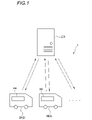
- FIG. 1 is a schematic diagram showing an example of a system including a stationary object information utilization device according to the first embodiment of the present disclosure.
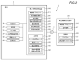
- FIG. 2 is a block diagram showing an example of a system including the stationary object information utilization device according to the first embodiment of the present disclosure.
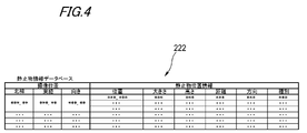
- FIG. 3 is an example of the stationary object database shown in FIG.
- FIG. 4 is an example of the stationary object database shown in FIG.
- FIG. 5 is a flow chart showing an example of a method for using stationary object information according to the first embodiment of the present disclosure.
- FIG. 6 is a schematic diagram for explaining areas for acquiring location information and stationary object information acquired by the control unit shown in FIG.
- FIG. 7 is a schematic diagram for explaining the positions of stationary objects indicated by the stationary object information shown in FIG. FIG.
- FIG. 8 is a schematic diagram for explaining the stationary object detection processing in step S306 shown in FIG.
- FIG. 9 is a schematic diagram for explaining the moving object detection processing in step S308 shown in FIG.
- FIG. 10 is a schematic diagram showing an example of a system including the stationary object information utilization device according to the second embodiment of the present disclosure.
- FIG. 11 is a block diagram showing an example of the system shown in FIG.
- FIG. 12 is a flow chart showing an example of a method for using stationary object information according to the second embodiment of the present disclosure.
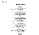
- FIG. 13 is a flowchart showing an example of light distribution pattern generation processing in step S414 shown in FIG.
- FIG. 14 is a schematic diagram showing positions of stationary objects when the vehicle shown in FIG. 11 passes through the first imaging position.
- FIG. 15 is a schematic diagram showing positions of stationary objects when the vehicle shown in FIG. 11 passes through the second imaging position.
- FIG. 16 is a schematic diagram showing an example of a system including the stationary object information utilization device according to the third embodiment of the present disclosure. 17 is a block diagram illustrating an example of the system shown in FIG. 16;
- FIG. 18 is a flow chart showing an example of a method for using stationary object information according to the third embodiment of the present disclosure.
- FIG. 19 is a schematic diagram for explaining an example of the stationary object area specifying process in step S50 shown in FIG.
- FIG. 20 is a schematic diagram for explaining an example of conditions for detecting a region of interest in step S60 shown in FIG. FIG.
- FIG. 21 is a schematic diagram for explaining another example of the region-of-interest detection conditions in step S60 shown in FIG.
- FIG. 22 is a schematic diagram showing an example of a system including a stationary object information acquisition device according to the fourth embodiment of the present disclosure.
- FIG. 23 is a block diagram showing an example of the system shown in FIG. 22;
- FIG. 24 is a flow chart showing an example of a method for using stationary object information according to the fourth embodiment of the present disclosure.
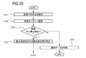
- FIG. 25 is a flow chart showing an example of the stationary object information identifying process in step S130 shown in FIG.
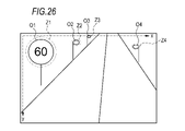
- FIG. 26 is a schematic diagram for explaining the stationary object position information indicating the stationary object position specified in step S134 shown in FIG.
- FIG. 27 is a flow chart showing another example of the stationary object information utilization method according to the fourth embodiment of the present disclosure.
- FIG. 28 is an example of the light distribution information database shown in FIG.
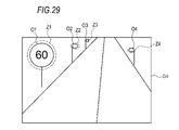
- FIG. 29 is a schematic diagram for explaining a light distribution pattern based on the light distribution information shown in FIG.
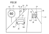
- FIG. 30 is a schematic diagram for explaining correction of the light distribution pattern shown in FIG.
- FIG. 1 is a schematic diagram showing a system 1.
- the system 1 includes a stationary object information storage device 200 and a plurality of vehicles 2 such as vehicles 2A and 2B each having a stationary object information utilization device 300 mounted thereon.
- the stationary object information storage device 200 and each vehicle 2 can be communicatively connected to each other by wireless communication.
- the vehicle 2 may further include a stationary object information acquisition device (not shown).
- the stationary object information acquisition device acquires stationary object information about a stationary object and transmits the stationary object information to the stationary object information storage device 200 .
- the stationary object information storage device 200 stores, for example, stationary object information received from each stationary object information acquisition device. Further, the stationary object information storage device 200 analyzes the received stationary object information, for example, improves the accuracy of the stationary object information, acquires more detailed information, and creates a light distribution pattern based on the stationary object information. Create.
- the stationary object information storage device 200 also transmits the stationary object information with improved accuracy to each vehicle 2 in response to a request from each vehicle 2, for example.
- Stationary object information utilization apparatus 300 may be configured to function also as a stationary object information acquisition apparatus.
- the "stationary object” in the present embodiment refers to an object that is fixed to the road and has a high brightness, and specifically includes a self-luminous body (for example, a street light, a traffic signal, etc.), a sign, a delineator, and guardrails. That is, the stationary object information acquiring apparatus according to the present embodiment acquires stationary object information related to the various stationary objects given as specific examples above. As another embodiment, the stationary object information acquisition device detects an object that is not included in the above specific examples, but is fixed to the road, has high brightness, and can affect target detection. It may be configured to be identifiable as
- FIG. 2 is a block diagram showing the system 1 according to the first embodiment of the present disclosure.
- the vehicle 2 includes a vehicle ECU (Electronic Control Unit) 10, a storage unit 20, a sensor unit 31, a position information acquisition unit 32, an illuminance sensor 33, a lamp ECU 40, and a stationary object information utilization device 300. ing.
- the vehicle 2 can communicate with the stationary object information storage device 200 by wireless communication via the communication network 3 .
- the means of wireless communication is not particularly limited, and for example, mobile communication systems such as telematics for automobiles, cooperation with smartphones, utilization of in-vehicle Wi-Fi, etc. may be used.
- the vehicle ECU 10 controls various operations such as running of the vehicle 2 .
- the vehicle ECU 10 includes, for example, a processor such as an ASIC (Application Specific Integrated Circuit), an FPGA (Field Programmable Gate Array), or a general-purpose CPU (Central Processing Unit).
- the storage unit 20 includes, for example, a ROM (Read Only Memory) storing various vehicle control programs and a RAM (Random Access Memory) temporarily storing various vehicle control data.
- the processor of the vehicle ECU 10 develops data designated by various vehicle control programs stored in the ROM onto the RAM, and controls various operations of the vehicle 2 in cooperation with the RAM.
- the sensor unit 31 outputs image data of an image of the exterior of the vehicle 2.
- the sensor unit 31 includes, for example, one or more sensors of a visible camera, LiDAR, and millimeter wave radar. Image data output by LiDAR and millimeter wave radar can be three-dimensional image data.
- the position information acquisition unit 32 outputs vehicle position information indicating the current position of the vehicle 2 .
- the position information acquisition unit 32 includes, for example, a GPS (Global Positioning System) sensor.
- the illuminance sensor 33 detects and outputs the illuminance around the vehicle 2 .
- the stationary object information utilization device 300 includes a control section 310 and a storage section 320 .
- the control unit 310 is configured by, for example, a processor such as a CPU.
- the control unit 310 can be configured as a part of the lamp ECU 40, for example. Further, the control unit 310 may be configured as a part of the vehicle ECU 10, for example.
- the storage unit 320 is configured by, for example, a ROM, a RAM, or the like.
- the storage unit 320 may be configured as part of a storage device provided for the storage unit 20 or the lamp ECU 40 .
- the control unit 310 controls the location information acquisition unit 331, the transmission/reception unit 332, the stationary object information acquisition unit 333, the image acquisition unit 334, the stationary object detection unit 335, and the mobile unit. It functions as the detection unit 336 . Note that part of these functions may be realized by the vehicle ECU 10 or the lamp ECU 40 . In such a configuration, the vehicle ECU 10 or the lamp ECU 40 forms part of the stationary object information utilization apparatus 300 . Also, the program 321 may be recorded on a non-temporary computer-readable medium.
- the location information acquisition unit 331 acquires location information that specifies at least one of the current location information of the vehicle 2, the destination information, the planned travel route information, and the home point information of the user of the vehicle 2.
- the location information can be obtained from a navigation system (not shown) mounted on the vehicle 2 or the position information obtaining section 32, for example.
- the vehicle ECU may intervene in the acquisition of the location information.
- the transmitting/receiving unit 332 selects between an image in which a still object exists or still object image data corresponding to a portion of the image, and still object position information indicating the position of the still object calculated based on the still object image data.
- a stationary object database 222 in which stationary object information 323 including at least one of them and imaging position information (vehicle position information at the time of imaging) 324 indicating the imaging position at which the still object image data was captured are recorded in association with each other. From the provided stationary object information storage device 200, the stationary object information and the imaging position information associated with each other are received by wireless communication.
- the transmitting/receiving unit 332 also transmits and receives other information to and from the vehicle ECU 10, the lamp ECU 40, and the stationary object information storage device 200 as necessary. That is, the transmitting/receiving section 332 functions as a transmitting section and a receiving section.
- the stationary object information acquisition unit 333 acquires information recorded in the stationary object database 222 , that is, the stationary object information 323 and the imaging position information 324 that are associated with each other, via the transmission/reception unit 332 .
- the stationary object information 323 acquired by the stationary object information acquiring unit 333 preferably includes at least one type of information of the type and size of the stationary object as the detailed information of the stationary object.
- the stationary object information acquisition unit 333 may be configured to acquire reference image data recorded in the stationary object database 222 .
- the reference image data is still object image data captured during the daytime.
- the reference image data is the image data 122 captured when the illuminance is equal to or higher than a predetermined value (for example, 1000 lux).
- the stationary object information acquisition unit 333 captures the stationary object information 323 corresponding to the location included in the location information acquired by the location information acquisition unit 331 or an area within a predetermined distance range (for example, within 1 km) from the location.
- Location information 324 is preferably obtained.
- the image acquisition unit 334 acquires the image data 322 of the current image (hereinafter also referred to as “current image”) captured by the sensor unit 31 when the vehicle 2 passes through the imaging position indicated by the imaging position information 324. .
- the stationary object detection unit 335 detects a stationary object at the imaging position indicated by the imaging position information 324 based on the stationary object information 323 and the imaging position information 324 . It is preferable that the stationary object detection unit 335 detects a stationary object in the current image based on the stationary object information 323 and the imaging position information 324 and the current image acquired by the image acquisition unit 334 . For example, the stationary object detection unit 335 may detect a stationary object by determining whether or not there is a stationary object at a position corresponding to the stationary object position indicated by the stationary object information 323 in the current image. The stationary object detection unit 335 may detect a stationary object based on a comparison between the reference image corresponding to the reference image data and the current image.
- the stationary object detection unit 335 can detect stationary objects by, for example, detecting light spots from the image or performing pattern recognition processing on the image.
- a conventionally known technique can be used for the detection of the light spot, and for example, it can be performed by luminance analysis of the image.
- a conventionally known method can be used as a pattern recognition method.
- a machine learning model may be used to detect a stationary object, or a clustering method may be used to detect a stationary object.
- the stationary object detection unit 335 335 detects stationary objects based on the current image. Note that when the position where the stationary object is estimated to exist based on the stationary object information 323 and the position where the stationary object is estimated to exist based on the current image are different, the transmitting/receiving unit 332 transmits the image data of the image. , to the stationary object information storage device 200 having the stationary object database 222 .
- the moving body detection unit 336 detects a moving body based on the current image.
- the moving object detection unit 336 detects, for example, an area in the current image other than the position corresponding to the position of the stationary object indicated by the stationary object information 323 and an area corresponding to the position of the stationary object where it is determined that there is no stationary object. may be targeted to detect a moving object. That is, when the stationary object detection unit 335 detects a stationary object in the current image at a position where the stationary object is estimated to exist based on the stationary object information 323, the moving object detection unit 336 detects the detected stationary object in the current image. The presence or absence of a moving object may be determined in an area excluding stationary objects. As with the stationary object detection unit 335, the moving object detection unit 336 may detect a moving object by performing light spot detection and pattern recognition processing. The moving object detection unit 336 may detect moving objects using other known techniques.
- control unit 310 serves as a light distribution unit that controls the light distribution of the headlights when the vehicle 2 passes through the imaging position indicated by the imaging position information 324 based on the stationary object information 323 and the imaging position information 324.
- the light distribution unit determines a first light distribution pattern based on the position of the stationary object detected by the stationary object detection unit 335 and the position of the moving object detected by the moving object detection unit 336.
- a third light distribution pattern may be generated by adding the second light distribution pattern, and the light distribution may be controlled based on the third light distribution pattern.
- the first light distribution pattern is, for example, a light distribution pattern created so as to be suitable for the position of a stationary object in the current image.
- the second light distribution pattern includes, for example, a light distribution instruction for the position of the moving object in the current image.
- the third light distribution pattern is, for example, obtained by adding the second light distribution pattern to the first light distribution pattern. More specifically, the third light distribution pattern may be obtained by overwriting the first light distribution pattern with the second light distribution pattern in the area where the moving object is located.
- the stationary object acquisition device acquires image data of an image captured by the sensor unit 31, for example.
- the still object acquisition device includes, for example, an image in which a still object exists or still object image data corresponding to a part of the image, and still object position information indicating the position of the still object calculated based on the image data;
- the stationary object information including at least one of is specified based on the image data.
- the stationary object information is specified, for example, by detecting light spots from the image or by subjecting the image to pattern recognition processing.
- a conventionally known technique can be used for the detection of the light spot, and for example, it can be performed by luminance analysis of the image.
- a conventionally known method can be used as a pattern recognition method.
- a machine learning model may be used to detect a stationary object, or a clustering method may be used to detect a stationary object.
- the stationary object acquisition device transmits, for example, stationary object information and vehicle position information when an image in which the stationary object information is specified is captured to the stationary object information storage device 200 .
- the stationary object information storage device 200 includes a control section 210 and a storage section 220 .
- the stationary object information storage device 200 is a computer device that aggregates and accumulates information transmitted from a plurality of vehicles 2, and is installed in a data center, for example.
- the control unit 210 is configured by, for example, a processor such as a CPU.
- the storage unit 220 is configured by, for example, a ROM, a RAM, or the like.
- the control unit 210 functions as the transmission/reception unit 211 by reading the program 221 stored in the storage unit 220 .
- the program 221 may be recorded on a non-temporary computer-readable medium.
- the transmission/reception unit 211 transmits and receives information to and from the vehicle ECU 10 and the stationary object information utilization device 300 . That is, the transmitting/receiving section 211 functions as a transmitting section and a receiving section.
- the transmitting/receiving unit 211 transmits the still object information 323 (which may include reference image data) recorded in the still object database 222 and the imaging position information 324 associated with the still object information 323 to the still object information utilization apparatus 300.
- the transmission/reception unit 211 receives, for example, stationary object information and imaging position information associated with the stationary object information from the stationary object information acquisition device. .
- the control unit 210 can also function as a recording unit that records each piece of information received from the stationary object information acquisition device in the stationary object database 222 . Further, the control unit 210 can execute, for example, a process of determining whether the stationary object information received from the stationary object information acquisition device is correct or an error, and a process of specifying detailed information.
- Imaging position information (vehicle position information) 324 and stationary object information 323 are associated and recorded in the stationary object database 222 .
- the stationary object database 222 for example, a plurality of pieces of stationary object image data can be recorded for one imaging position indicated by the vehicle position information 324 .
- stationary object image data and reference image data having the same imaging position can be associated and recorded.
- detailed information such as the position and size of the stationary object, the distance and direction from the imaging position, and the type of the stationary object can be recorded in association with the imaging position.
- the stationary object database 222 records a plurality of pieces of still object image data and reference image data in association with imaging positions.
- the imaging position the latitude and longitude of the imaging position and the orientation of the vehicle 2 at the time of imaging (for example, the orientation of the visible camera) are recorded.
- the stationary object image data an ID for identifying the stationary object image data, time information, illuminance information, and lighting information are recorded.
- An ID for identification is recorded in the reference image data.
- the reference image data may further include information similar to that of the still object image data.
- Still object image data whose illuminance indicated by the illuminance information is equal to or greater than a predetermined value may be treated as reference image data.
- the stationary object database 222 records a plurality of pieces of stationary object position information in association with the imaging position.
- the stationary object position information detailed information such as the stationary object position, size, height, distance and direction from the imaging position, and stationary object type is recorded. Note that when only one stationary object is identified at a certain imaging position, one piece of stationary object position information can be associated with that imaging position.
- the stationary object position can be identified using, for example, an arbitrary coordinate system set in the image.
- the stationary object position may indicate, for example, the center point of the stationary object or the position of the outer edge of the stationary object.
- the position of the stationary object preferably includes information about the size specified using the coordinate system.
- the stationary object position may indicate the distance and direction from the imaging position of the image to the stationary object.
- the distance and direction from the imaging position to the stationary object may be calculated using the depth information. Further, it may be calculated by comparison with other image data captured near the imaging position, or may be calculated using data obtained from millimeter wave radar or LiDAR.
- FIGS. 3 and 4 show an example of information recorded in the stationary object database 222, and some information may not be recorded, and other information may be included. From the viewpoint of increasing the accuracy of the determination process described above by the control unit 210 and increasing the utility value of the still object database 222, the still object database 222 should include both still object image data and still object position information. is preferred.
- the stationary object database 222 may be managed as an individual database for each vehicle 2, for example. In this case, information accumulated in one database is based on information transmitted from one vehicle 2 . Also, the stationary object database 222 may be managed as a database of the entire plurality of vehicles 2, for example. In this case, multiple pieces of information transmitted from multiple vehicles 2 are aggregated in one database.
- the stationary object database 222 may be managed as a database for each model of the vehicle 2, for example.
- a plurality of pieces of information transmitted from a plurality of vehicles 2 of the same vehicle type are aggregated.
- the stationary object information storage device 200 receives the stationary object information and the like from the stationary object acquisition device, the model information of the vehicle 2 is also received. It may be configured to record vehicle type information.
- the stationary object information storage device 200 may be mounted on the vehicle 2.
- control unit 210 and storage unit 220 may be provided separately from vehicle ECU 10 , control unit 310 , storage unit 20 , and storage unit 320 .
- the control unit 210 may be configured as a part of any one or more of the lamp ECU 40, the vehicle ECU 10, and the control unit 310, for example.
- part of the functions of the control unit 210 may be implemented by the vehicle ECU 10 or the lamp ECU 40 .
- the storage unit 220 may be configured as a part of one or more of the storage unit 20, the storage unit 320, or a storage device provided for the lamp ECU 40, for example.
- the stationary object information storage device 200 is installed in the vehicle 2, the stationary object information utilization device 300 and the stationary object information storage device 200 are configured to be connectable by wireless communication or wired communication.
- the static object information utilization method is executed by, for example, the control unit 310 of the static object information utilization device 300 loaded with the program 321 and the control unit 210 of the static object information storage device 200 loaded with the program 221. .
- the still object information utilization device 300 detects a stationary object or the like using the still object information 323 and the current image captured by the visible camera will be described as an example. It is not limited to this.
- the stationary object information utilization apparatus 300 may detect a stationary object or the like, for example, using the stationary object information 323 and the current image output by the millimeter wave radar or LiDAR.
- FIG. 5 is a flowchart showing an example of a stationary object information utilization method according to this embodiment. It should be noted that the order of each process constituting each flowchart described in this specification may be random as long as there is no contradiction or inconsistency in the contents of the process, and the processes may be executed in parallel.
- step S301 the control unit 310 acquires at least one or more location information out of the current location information of the vehicle 2, the destination information, the planned travel route information, and the home location information of the user of the vehicle 2.
- step S302 the control unit 310 transmits the stationary object information 323 and the imaging position information 324 corresponding to the location included in the location information acquired in step S301 or an area within a predetermined distance range from the location. is requested to the stationary object information storage device 200 .
- Step S302 may be executed, for example, based on the operation of the user of the vehicle 2, or when the vehicle 2 is activated at a predetermined timing (for example, when the engine of the vehicle 2 is started, or when the planned travel route of the vehicle 2 is determined). , when the vehicle 2 is stopped or slowed down, when the program 121 is updated, etc.).
- FIG. 6 is a schematic diagram for explaining the area for acquiring the location information and the stationary object information 323 acquired by the control unit 310.
- a current location (start point) A1, a destination A2, a planned travel route R, and an area Q are shown on the map.
- a current position A1 indicates the current position of the vehicle 2 .
- Destination A2 indicates, for example, the destination of vehicle 2 entered into the navigation system by the user of vehicle 2 .
- the planned travel route R indicates a route from the current location A1 to the destination A2, which is calculated by the navigation system and selected by the user of the vehicle 2, for example. Information about these points and routes can be obtained from, for example, a navigation system.
- the area Q is an area within a predetermined distance range from the current location A1, the destination A2, and the planned travel route R.
- the predetermined distance range may be set by the user.
- home point information indicating the home point (not shown) of the user of the vehicle 2 may be acquired as the location information, and the region Q may include a predetermined distance range from the home point.
- the predetermined distance range may be different for one or more of the current location A1, the destination A2, the planned travel route R, and the home location.
- the region Q may be set by making the distance range from the home point larger than the distance range from the planned travel route R or the like.
- the stationary object information 323 of the place where the passage frequency or the possibility of being passed is high can be acquired. becomes possible. Moreover, as a result, an increase in the amount of communication and an increase in the size of the storage unit 320 can be suppressed.
- step S303 the control unit 210 converts the still object information 323 and the imaging position information 324 indicating the imaging position associated with the still object information 323 into the stationary object information. It transmits to the utilization device 300 . From the viewpoint of increasing the range of utilization of the stationary object information 323 in the vehicle 2 and improving the detection accuracy of the stationary object, in step S303, the reference image data at the imaging position and the detailed information of the stationary object are also transmitted. preferably.
- step S ⁇ b>303 the control unit 210 transmits the stationary object information 323 and the imaging position information 324 indicating the imaging position associated with the stationary object information 323 to the stationary object information utilization device 300 .
- the reference image data at the imaging position and the detailed information of the stationary object are also transmitted. preferably.
- step S304 the control unit 310 receives each piece of information transmitted in step S303.
- step S ⁇ b>305 the control unit 310 acquires the current image captured by the visible camera when the vehicle 2 passes through the imaging position indicated by the imaging position information 324 .
- step S306 the control unit 310 detects a stationary object from the current image, for example, based on the stationary object information 323 and the current image. In step S306, for example, it is determined whether or not a stationary object exists in the current image at the position indicated by the stationary object information 323 (the position where the stationary object is estimated to exist based on the stationary object information 323).
- the control unit 310 detects the presence or absence of a moving object in the area excluding the detected stationary object, and terminates.
- the detected position of a stationary object and the position of a moving object can be used, for example, for light distribution control of headlights, target detection in automatic driving, and the like.
- control unit 310 detects a position indicated by stationary object information 323 where no stationary object is detected. The presence or absence of a moving object is detected in an area including . Further, in step S ⁇ b>309 , control unit 310 transmits image data of the current image and imaging position information 324 of the current image to stationary object information storage device 200 . Note that even if a stationary object is detected at a position other than the position indicated by the stationary object information 323 in step S306, the processing from step S309 onward can be performed.
- step S310 the control unit 210 receives each piece of information transmitted at step S309.
- step S311 the control unit 210 updates the stationary object database 222 so that the information received in step S310 is included in the stationary object database 222, and ends the process.
- the control unit 210 may specify the position of the still object in the current image data based on the current image data received in step S309 and the still object information 323 recorded in the still object database. In this case, it is preferable to use an algorithm different from the processing of step S306 and with higher accuracy.
- step S309 As a result of this identification, if it is determined that the stationary object information 323 recorded in the stationary object database 222 is correct and the detection result in step S306 is incorrect, each piece of information transmitted in step S309 may be deleted. By executing a series of processes after step S309, it is possible to further improve the accuracy of the stationary object information 323 recorded in the stationary object database 222.
- FIG. 7 is a schematic diagram for explaining the positions of stationary objects indicated by the stationary object information 323 shown in FIG.
- FIG. 8 is a schematic diagram for explaining the stationary object detection processing in step S306.
- FIG. 9 is a schematic diagram for explaining the moving object detection processing in step S308.
- the stationary object information 323 acquired from the stationary object information storage device 200 includes information that stationary objects are present in the areas Z1 to Z4.
- the stationary object information 323 includes information regarding the position of the stationary object defined using the coordinates defined by the x-axis and the y-axis.
- step S306 it is determined whether or not there is a stationary object in the areas Z1 to Z4 using techniques such as light spot detection and pattern recognition processing.
- stationary objects O1 to O4 are detected in areas Z1 to Z4, respectively. Therefore, in step S307, moving object detection processing is performed on areas other than the areas Z1 to Z4. By configuring in this way, it is possible to reduce the area where the moving object detection processing is performed, so that the processing load on the control unit 310 can be reduced.
- other vehicles C1 and C2 are detected as moving objects.
- the other vehicle C1 is detected based on the light spots of the rear lamps BL1 and BL2, for example.
- another vehicle C2 is detected, for example, based on light spots such as headlights HL1 and HL2.
- the detection of a stationary object is not particularly limited, but for example, from the viewpoint of reducing the processing load, it is performed depending on whether or not a light spot that is estimated to be a stationary object is detected in each of the regions Z1 to Z4. good too. Further, when the stationary object information 323 is not used, even if a light spot is detected, the load on the control unit 310 can be reduced by determining whether it is caused by a stationary object or a moving object. They may grow up or make mistakes in judgment. For example, if the distance between two stationary objects is approximately the same as the distance between left and right lamps of a car, the two stationary objects may be erroneously determined to be moving objects. On the other hand, by using the stationary object information 323, it can be estimated that the light spot existing at the position of the stationary object indicated by the stationary object information 323 is caused by the stationary object. It is expected that the accuracy of determination of stationary objects will be improved.
- regions Z1 to Z4 are superimposed on a current image CI2 different from the current image CI1.
- stationary objects O1 to O2 and O4 are detected in areas Z1 to Z2 and Z4, respectively, but no stationary object is detected in area Z3.
- moving object detection processing is performed on areas other than the areas Z1 to Z2 and Z4.
- the area Z3 is the target of the moving object detection processing.
- the image data of the current image CI2 is transmitted to the still object information storage device 200.
- FIG. In the stationary object information storage device 200 for example, whether or not a stationary object really exists in the area Z3 of the current image CI2 can be determined by an algorithm different from that in step S306.
- stationary objects may be detected in addition to areas other than the areas Z1 to Z4.
- the control unit 310 determines that the stationary object exists in the other area.
- the current images CI1 and CI2 are transmitted to the stationary object information storage device 200.
- FIG. in the still object information storage device 200 for example, whether or not a still object really exists in other areas of the current images CI1 and CI2 can be determined by an algorithm different from that in step S306.
- the stationary object information utilization device 301 according to the second embodiment of the present disclosure will be described.
- Components of the stationary object information utilization device 301 are the same as those of the stationary object information utilization device 300 according to the first embodiment, except for the configurations described below, and the same reference numerals are used.
- FIG. 10 is a schematic diagram showing an example of the system 1 including the stationary object information utilization device 301 according to the second embodiment of the present disclosure.
- the stationary object information utilization device 301 is mounted on the vehicle 2 included in the system 1, as shown in FIG.
- FIG. 11 is a block diagram showing an example of the system 1 shown in FIG.
- the vehicle 2 includes a vehicle ECU 10 , a storage unit 20 , a sensor unit 31 , a position information acquisition unit 32 , an illuminance sensor 33 , a lamp ECU 40 and a stationary object information utilization device 301 .
- the stationary object information utilization device 301 includes a control section 310 and a storage section 320 .
- the control unit 310 controls the transmission/reception unit 332, the stationary object information acquisition unit 333, the image acquisition unit 334, the stationary object detection unit 335, the moving object detection unit 336, and the light distribution unit. 337 , regression analysis unit 338 , and vehicle information acquisition unit 339 . Note that part of these functions may be realized by the vehicle ECU 10 or the lamp ECU 40 .
- the transmitting/receiving section 332 functions as a transmitting section and a receiving section.
- the stationary object information acquiring unit 333 acquires information recorded in the stationary object database 222 , that is, the stationary object information 323 and the imaging position information 324 that are associated with each other, via the transmitting/receiving unit 332 .
- the stationary object information 323 acquired by the stationary object information acquisition unit 333 includes at least information on the type and size of the stationary object and the image intensity of the position of the stationary object in the stationary object image data as the detailed information on the stationary object. Preferably, one or more types of information are included.
- the stationary object information acquisition unit 333 may be configured to acquire reference image data recorded in the stationary object database 222 .
- the light distribution unit 337 controls the light distribution of the headlights when the vehicle 2 passes through the imaging position indicated by the imaging position information 324 based on the stationary object information 323 and the imaging position information 324 .
- the light distribution unit 337 further distributes the light based on the detailed information including at least one of information on the type and size of the stationary object, and information on the image intensity of the position of the stationary object in the stationary object image data. may be controlled.
- the light distribution unit 337 detects the first light distribution pattern based on the position of the stationary object detected by the stationary object detection unit 335, and the position of the moving object detected by the moving object detection unit 336.
- a third light distribution pattern is generated by adding the determined second light distribution pattern, and the light distribution is controlled based on the third light distribution pattern.
- the first light distribution pattern is, for example, a light distribution pattern created to be suitable for the position of a stationary object in the current image.
- the second light distribution pattern includes, for example, a light distribution instruction for the position of the moving object in the current image.
- the third light distribution pattern is, for example, obtained by adding the second light distribution pattern to the first light distribution pattern. More specifically, the third light distribution pattern may be obtained by overwriting the first light distribution pattern with the second light distribution pattern in the area where the moving object is located.
- the light distribution unit 337 determines that the vehicle 2 passes through the first imaging position and the distance to the second imaging position that the vehicle is scheduled to pass next satisfies a predetermined condition (for example, within 10 m). is satisfied, light distribution can be controlled. Moreover, the light distribution unit 337 may further control light distribution based on vehicle information acquired by the vehicle information acquisition unit 339 .
- the light distribution unit 337 can control one or more of light distribution for low beam and light distribution for high beam. Also, the light distribution unit 337 may output light distribution information defining a light distribution pattern to the lamp ECU.
- the light distribution information may be information in any format, for example, information on one or more of gradation values, current values, and light shielding angles for a plurality of light sources included in the headlamp. Alternatively, image data representing a light distribution pattern may be used.
- the regression analysis unit 338 performs the first Based on the first stationary object information 323 corresponding to the imaging position of and the second stationary object information 323 corresponding to the second imaging position, stillness between the first imaging position and the second imaging position Object positions are calculated by regression analysis.
- the method of regression analysis is not particularly limited, and conventionally known methods can be used.
- One example of regression analysis is linear interpolation.
- the regression analysis unit 338 may further calculate the position of a stationary object between the first imaging position and the second imaging position based on the position of the road and the direction in which the road extends at each imaging position. good.
- the regression analysis unit 338 may also calculate the positions of the stationary objects between the imaging positions based on the stationary object information 323 at three or more imaging positions where the distance between the imaging positions satisfies a predetermined condition.
- the vehicle information acquisition unit 339 acquires vehicle information including at least one type of information among the direction in which the vehicle 2 is facing and the position in the vehicle width direction in the driving lane.
- the position in the vehicle width direction in the driving lane can be calculated, for example, based on the position of the driving lane in the current image.
- the direction in which the vehicle 2 is facing can be calculated based on the transition of the vehicle position information output by the position information acquisition unit 32, for example.
- the vehicle information acquisition unit 339 may further acquire information about the steering angle of the steering wheel that can be acquired from the vehicle ECU 10 .
- the stationary object information storage device 200 includes a control section 210 and a storage section 220 .
- the control unit 210 functions as a transmission/reception unit 211 by reading a program 221 stored in the storage unit 220 .
- Imaging position information (vehicle position information) 324 and stationary object information 323 are associated and recorded in the stationary object database 222 .
- the stationary object database 222 for example, a plurality of pieces of stationary object image data can be recorded for one imaging position indicated by the vehicle position information 324 . Further, in the stationary object database 222, stationary object image data and reference image data having the same imaging position can be associated and recorded.
- the stationary object database 222 In the stationary object database 222, detailed information such as the position and size of the stationary object, the distance and direction from the imaging position, the type of the stationary object, and the image intensity of the position of the stationary object in the still object image is stored at the imaging position. can be recorded in association.
- a plurality of still object image data and reference image data are recorded in the stationary object database 222 in association with the imaging position.
- the imaging position the latitude and longitude of the imaging position and the orientation of the vehicle 2 at the time of imaging (for example, the orientation of the visible camera) are recorded.
- the stationary object image data an ID for identifying the stationary object image data, time information, illuminance information, and lighting information are recorded.
- An ID for identification is recorded in the reference image data.
- the reference image data may further include information similar to that of the still object image data.
- Still object image data whose illuminance indicated by the illuminance information is equal to or greater than a predetermined value may be treated as reference image data.
- the stationary object database 222 records a plurality of pieces of stationary object position information in association with the imaging position.
- the stationary object position information detailed information such as the position of the stationary object, size, height, distance and direction from the imaging position, type of the stationary object, and image intensity of the position of the stationary object in the still object image is recorded. . Note that when only one stationary object is identified at a certain imaging position, one piece of stationary object position information can be associated with that imaging position.
- the static object information utilization method is executed by, for example, the control unit 310 of the static object information utilization device 301 loaded with the program 321 and the control unit 210 of the static object information storage device 200 loaded with the program 221. .
- the still object information utilization device 301 controls the light distribution using the still object information 323 and the current image captured by the visible camera as an example.
- the stationary object information utilization device 301 may control light distribution using, for example, the stationary object information 323 and the current image output by the millimeter wave radar or LiDAR.
- FIG. 12 is a flow chart showing an example of a method for using stationary object information according to this embodiment. It should be noted that the order of each process constituting each flowchart described in this specification may be random as long as there is no contradiction or inconsistency in the contents of the process, and the processes may be executed in parallel.
- step S411 the control unit 310 requests the stationary object information storage device 200 to transmit the stationary object information 323 at a predetermined imaging position.
- Step S411 may be executed, for example, based on the operation of the user of the vehicle 2, or when the vehicle 2 is operated at a predetermined timing (for example, when the engine of the vehicle 2 is started, when the planned travel route of the vehicle 2 is determined). , when the vehicle 2 is stopped or slowed down, when the program 121 is updated, etc.).
- the predetermined imaging position is not particularly limited, for example, from the viewpoint of high usability for the user of the vehicle 2, the current value of the vehicle 2, the destination, the planned travel route, and the home of the user of the vehicle 2 A position within a predetermined distance range is preferable.
- the control unit 210 Upon receiving the request from the still object information utilization apparatus 301, in step S412, the control unit 210 converts the still object information 323 and the imaging position information 324 indicating the imaging position associated with the still object information 323 into the stationary object information. It transmits to the utilization device 301 . From the viewpoint of realizing a more suitable light distribution, it is preferable to transmit the reference image data and the detailed information of the stationary object at the imaging position in step S412.
- step S413 the control unit 310 receives each piece of information transmitted in step S412.
- step S414 the control unit 310 generates a light distribution pattern of the headlights at the imaging position indicated by the imaging position information 324 associated with the stationary object information 323 based on the stationary object information 323 and the like, and ends the process. do.
- FIG. 13 is a flowchart showing an example of light distribution pattern generation processing in step S414 shown in FIG. First, in step S ⁇ b>421 , the control unit 310 acquires the current image captured by the visible camera when the vehicle 2 passes the imaging position indicated by the imaging position information 324 .
- step S422 the control unit 310 acquires vehicle information.
- the vehicle information may be the direction in which the vehicle 2 is facing, the position in the vehicle width direction in the driving lane of the vehicle 2, or both of them.
- step S422 information regarding the steering angle of the steering wheel may be obtained.
- step S423 the control unit 310 corrects the stationary object information 323 based on the vehicle information acquired in step S422.
- the stationary object information 323 specifies a stationary object based on the image captured at that imaging position. Therefore, depending on the direction in which the vehicle 2 is facing or the position in the vehicle width direction, the position of the stationary object indicated by the stationary object information 323 may deviate from the position of the stationary object in the current image. Therefore, by performing the processing of step S423, the above deviation can be eliminated, and the accuracy of detecting a stationary object in the current image, which will be described later, can be improved. It should be noted that if there is little deviation as described above, the process of step S423 may not be executed.
- the stationary object information 323 may not be used in generating the light distribution pattern. good.
- the position of the stationary object in the current image and the position of the stationary object indicated by the stationary object information 323 are greatly displaced. is not expected.
- step S424 the control unit 310 detects a stationary object from the current image based on the stationary object information 323 corrected in step S423.
- step S425 control unit 310 generates a first light distribution pattern based on the position of the stationary object detected in step S424.
- the light distribution information defining the first light distribution pattern may be stored in the storage unit 320, and the first light distribution pattern may be reused when passing through that position again next time.
- the first light distribution pattern includes at least one type of detailed information among the size and type of the stationary object, and the image intensity of the position of the stationary object in the still object image data. It is preferably made on the basis of The first light distribution pattern is obtained by, for example, dimming the position of a stationary object with reference to a normal light distribution pattern for low beam or high beam.
- the user of the vehicle 2 may feel dazzled by the reflected light from the stationary object. is preferably dimmed.
- the light may be distributed as normal for a stationary object for which the reflected light is not a problem.
- whether or not the object is a high-brightness reflecting object may be determined based on information regarding the type of the stationary object and the image intensity of the position of the stationary object in the still object image.
- the information about the image intensity may be, for example, the gradation value of the image.
- the stationary object may be determined as a high-brightness reflecting object.
- the stationary object may be determined as the high-brightness reflecting object.
- control unit 310 detects a moving object from the current image.
- control unit 310 generates a second light distribution pattern based on the position of the moving object detected in step S426.
- control unit 310 generates a third light distribution pattern based on the first light distribution pattern and the second light distribution pattern.
- the control unit 310 outputs light distribution information defining the third light distribution pattern to the headlamp or the lighting ECU 40 or the like, so that the headlamp is controlled to distribute light based on the third light distribution pattern.
- the stationary object information 323 acquired from the stationary object information storage device 200 includes information that stationary objects are present in the areas Z1 to Z4.
- the first light distribution pattern is, for example, a normal light distribution pattern with dimming for the regions Z1 to Z4 added.
- the areas in which no stationary object is detected are not dimmed.
- the object of the moving object detection processing is, for example, the areas other than the areas Z1 to Z4.
- the second light distribution pattern is, for example, one that dims or shades the regions Z5 and Z6.
- the third light distribution pattern is obtained by adding dimming to the regions Z1 to Z4 and dimming or blocking to the regions Z5 to Z6 in the normal light distribution pattern.
- priority may be given to light reduction or light shielding for the area of the moving object.
- the other vehicle C1 is detected, for example, based on the light spots of the rear lamps BL1 and BL2.
- another vehicle C2 is detected, for example, based on light spots such as headlights HL1 and HL2.
- stationary object information 323 that has been acquired in advance is used to detect stationary objects and moving objects. The required time and load can be reduced.
- FIG. 14 is a schematic diagram showing positions of stationary objects when the vehicle 2 passes through the first imaging position.
- FIG. 15 is a schematic diagram showing the positions of stationary objects when the vehicle 2 passes through the second imaging position.
- the second imaging position is, for example, a position within 10 m from the first imaging position.
- the second imaging position is, for example, a position where the vehicle 2 has advanced without changing the traveling direction from the first imaging position.
- the stationary object information 323 includes information about the position of the stationary object defined using the coordinates defined by the x-axis and the y-axis.
- FIG. 14 shows that stationary objects O11 and O12 are present at the positions shown in the figure at the first imaging position. Further, in the example of FIG. 15, the relative positions of the stationary objects O11 and O12 with respect to the vehicle 2 change due to the forward movement of the vehicle 2, and the stationary objects O11′ and O12′ are present. is shown.
- the control unit 310 calculates the position of the stationary object 11 assuming that the stationary object 11 apparently moves within the region Z11 between the first imaging position and the second imaging position, and the calculation result is Based on this, for example, each process of steps S424 to S428 is executed. Similarly, after passing the second imaging position, the position of the stationary object 11 can be calculated assuming that the stationary object 11 apparently moves within the area Z11. Similarly, the stationary object 12 and the stationary object O12' are considered to apparently move within the region Z12 extending so as to connect the stationary object 12 and the stationary object O12'.
- each configuration of the stationary object information utilization device 302 is the same as each configuration of the stationary object information utilization device 300 according to the first embodiment, and the same reference numerals are used.
- FIG. 16 is a schematic diagram showing an example of the system 1 including the stationary object information utilization device 302 according to the third embodiment of the present disclosure.
- the stationary object information utilization device 302 is mounted on the vehicle 2 included in the system 1, as shown in FIG.
- FIG. 17 is a block diagram showing an example of the system 1 shown in FIG.
- the vehicle 2 includes a vehicle ECU 10 , a storage unit 20 , a sensor unit 31 , a position information acquisition unit 32 , an illuminance sensor 33 , a lamp ECU 40 and a stationary object information utilization device 302 .
- the stationary object information utilization device 302 includes a control section 310 and a storage section 320 .
- the control unit 310 controls the transmission/reception unit 311 , the stationary object information acquisition unit 312 , the image acquisition unit 313 , the stationary object region identification unit 314 , the detection condition determination unit 315 , and the interest detection unit 315 . It functions as the area specifying unit 316 . Note that part of these functions may be realized by the vehicle ECU 10 or the lamp ECU 40 .
- the transmitting/receiving unit 311 functions as a transmitting unit and a receiving unit.
- the stationary object information acquisition unit 312 acquires information recorded in the stationary object database 222 , that is, the stationary object information 323 and the imaging position information 324 that are associated with each other, via the transmitting/receiving unit 311 .
- the stationary object information 323 acquired by the stationary object information acquiring unit 312 preferably includes at least one or more information of the type and size of the stationary object as the detailed information of the stationary object. Further, the stationary object information acquisition unit 312 may be configured to acquire reference image data recorded in the stationary object database 222 .
- the stationary object region identifying unit 314 identifies the current image captured by the sensor unit 31 when the vehicle 2 passes the position indicated by the imaging position information 324 associated with the stationary object information 323 and the stationary object information 323. to specify a stationary object region in which the stationary object exists in the current image. For example, the stationary object region identification unit 314 detects a stationary object region by determining whether or not there is a stationary object in the region corresponding to the position of the stationary object indicated by the stationary object information 323 in the current image. good. The stationary object region identifying section 314 may detect the stationary object region based on a comparison between the reference image corresponding to the reference image data and the current image.
- the stationary object region identifying unit 314 can identify the stationary object region by detecting a stationary object, for example, by detecting light spots from the image or performing pattern recognition processing on the image.
- the stationary object region identifying unit 314 Based on this, a stationary object is detected and a stationary object area is specified. Note that when the position where the stationary object is estimated to exist based on the stationary object information 323 and the position where the stationary object is estimated to exist based on the current image are different, the transmitting/receiving unit 311 transmits the image data of the image. , to the stationary object information storage device 200 having the stationary object database 222 .
- a detection condition determining unit 315 determines conditions for detecting a region of interest in the current image based on the stationary object region specified by the stationary object region specifying unit 314 .
- the area of interest is not particularly limited, but for example, there are moving objects such as other vehicles and pedestrians that are watched in ADAS (Advanced Driver-Assistance Systems) and AD (Autonomous Driving) It can be an area where ADAS (Advanced Driver-Assistance Systems) and AD (Autonomous Driving) It can be an area where
- the detection condition determination unit 315 determines the region below the straight line connecting the plurality of still object regions in the current image as the detection range of the region of interest. In addition, for example, the detection condition determination unit 315 performs detection processing of a region of interest in a region below a straight line connecting a plurality of stationary object regions in the current image more than the number of times of detection processing of a region of interest in a region above the straight line. The number of detection processing times of the region of interest may be determined so as to increase the number of times.
- the detection condition determination unit 315 may determine, for example, a masked image obtained by masking a still object region in the current image as a region of interest detection target. Further, when the stationary object information 323 includes information about the type of the stationary object, and when the plurality of stationary objects included in the current image are the same type of stationary objects, the detection condition determination unit 315 determines the same type of stationary object. A masked image obtained by masking a region formed to include a plurality of stationary objects may be determined as a region of interest detection target. Also, the range to be masked is preferably a range obtained by adding a predetermined margin to the stationary object area.
- the region-of-interest identifying unit 316 identifies the region of interest in the current image based on the detection conditions determined by the detection condition determining unit 315 .
- a technique for identifying the region of interest is not particularly limited, and conventionally known techniques can be used.
- the region-of-interest identifying unit 316 may identify the region of interest by detecting light spots from the current image or performing pattern recognition processing on the current image, similarly to the stationary object region-identifying unit 314 .
- the stationary object information utilization method is executed by, for example, the control unit 310 of the stationary object information utilization device 302 loaded with the program 321 and the control unit 210 of the stationary object information storage device 200 loaded with the program 221. .
- the still object information utilization device 302 included in the system 1 identifies the region of interest using the still object information 323 and the current image captured by the visible camera will be described as an example.
- the disclosure is not so limited.
- the stationary object information utilization apparatus 302 may specify the region of interest using, for example, the stationary object information 323 and the current image output by the millimeter wave radar or LiDAR.
- FIG. 18 is a flow chart showing an example of a method for using stationary object information according to this embodiment. It should be noted that the order of each process constituting each flowchart described in this specification may be random as long as there is no contradiction or inconsistency in the contents of the process, and the processes may be executed in parallel.
- step S10 the control unit 310 requests the stationary object information storage device 200 to transmit the stationary object information 323 at a predetermined imaging position.
- Step S10 may be executed, for example, based on the operation of the user of the vehicle 2, or when the vehicle 2 is operated at a predetermined timing (for example, when the engine of the vehicle 2 is started, when the planned travel route of the vehicle 2 is determined). , when the vehicle 2 is stopped or slowed down, when the program 121 is updated, etc.).
- the predetermined imaging position is not particularly limited, for example, from the viewpoint of high usability for the user of the vehicle 2, the current value of the vehicle 2, the destination, the planned travel route, and the home of the user of the vehicle 2 A position within a predetermined distance range is preferable.
- step S20 the control unit 210 converts the still object information 323 and the imaging position information 324 indicating the imaging position associated with the still object information 323 into the stationary object information. It transmits to the utilization device 302 . From the viewpoint of further increasing the accuracy of specifying the region of interest, it is preferable to transmit the reference image data at the imaging position and the detailed information on the type and size of the stationary object in step S20.
- step S30 the control unit 310 receives each piece of information transmitted in step S20.
- step S ⁇ b>40 the control unit 310 acquires the current image captured by the visible camera when the vehicle 2 passes through the imaging position indicated by the imaging position information 324 .
- step S50 the control unit 310 identifies a still object area in the current image based on the still object information 323 and the current image.
- step S60 the control unit 310 determines conditions for detecting the region of interest in the current image based on the still object information 323 and the current image, based on the still object region identified in step S50.
- step S70 the control unit 310 identifies a region of interest in the current image based on the detection conditions determined in step S60, and terminates.
- FIG. 19 is a schematic diagram for explaining an example of the stationary object area specifying process in step S50.
- FIG. 20 is a schematic diagram for explaining an example of conditions for detecting a region of interest in step S60.
- FIG. 21 is a schematic diagram for explaining another example of the region-of-interest detection conditions in step S60.
- the stationary object information 323 acquired from the stationary object information storage device 200 includes information that stationary objects are present in the areas Z1 to Z3.
- regions Z1 to Z3 are superimposed on the current image CI3.
- other vehicles C1 and C2 are shown in the current image CI3.
- step S50 it is determined whether or not there is a stationary object in the areas Z1 to Z3 using methods such as light spot detection and pattern recognition processing.
- a stationary object In the example of FIG. 19, stationary objects O1 to O3 are detected in areas Z1 to Z3, respectively. Therefore, in step S50, the areas Z1 to Z3 are identified as stationary object areas. Further, in step S50, detailed information such as the type and size of the stationary object may be used to specify the type and size of the stationary object existing in each stationary object region.
- the method of detecting a stationary object is not particularly limited, for example, from the viewpoint of reducing the processing load, it is possible to you can go Further, when the stationary object information 323 is not used, even if a light spot is detected, the load on the control unit 310 can be reduced by determining whether it is caused by a stationary object or a moving object. They may grow up or make mistakes in judgment. For example, if the distance between two stationary objects is approximately the same as the distance between left and right lamps of a car, the two stationary objects may be erroneously determined to be moving objects. On the other hand, by using the stationary object information 323, it can be estimated that the light spot existing at the position of the stationary object indicated by the stationary object information 323 is caused by the stationary object. It is expected that the accuracy of determination of stationary objects will be improved.
- a straight line L connecting areas Z1 to Z3 identified as stationary object areas is shown.
- the straight line L may be, for example, an approximate straight line based on the central points or the barycentric points of the regions Z1-Z3.
- the detection conditions are determined such that the lower region Ar1 below the straight line L is determined as the region of interest detection range, and the upper region Ar2 above the straight line L is not the region of interest detection range.
- the road is considered to exist in the area Ar1 below the straight line L connecting the areas Z1 to Z3 identified as stationary object areas.
- the area Ar2 above the straight line L does not include the road. Therefore, the region of interest (moving body) detection target is not set for the upper region Ar2, and only the lower region Ar1 where the road exists is set as the region of interest detection target, thereby significantly reducing the detection accuracy of the region of interest. It is possible to reduce the load on the control unit 310 without
- the straight line L preferably connects stationary object areas in which stationary objects of the same type exist. This is because stationary objects of the same type often have the same actual height, and there is a high probability that the lower area Ar1 includes the road.
- a straight line L is a line connecting stationary object areas between stationary objects located on the same side of the road (for example, stationary objects located on the right side of the road or stationary objects located on the left side of the road). is preferably Also in this case, the probability that a road is included in the lower area Ar1 increases.
- FIG. 21 shows a state in which areas Z1 to Z3 specified as stationary object areas are masked.
- the mask processing is processing for excluding the masked region from the region of interest detection target.
- the mask processing is performed, for example, by minimizing the gradation value of the luminance value of that area.
- the regions excluding the masked regions Z1 to Z3 are the detection target of the region of interest. In this case, it is possible to reduce the load on the control unit 310 without lowering the detection accuracy of the region of interest.
- the region where the masking process is performed is preferably a range obtained by adding a predetermined margin to the regions Z1 to Z3, which are stationary object regions, that is, a range larger than the regions Z1 to Z3.
- the predetermined margin is preferably large enough to prevent the person from being completely hidden.
- mask processing may be performed on an area formed so as to collectively include the plurality of stationary objects of the same type. That is, by grouping stationary objects of the same type, it becomes possible to apply mask processing to a wider area, and as a result, it is possible to further reduce the load on the control unit 310 .
- the area where the other vehicles C1 and C2 are present can be identified as the area of interest.
- FIG. 22 is a schematic diagram showing an example of the system 1 including the stationary object information acquisition device 100 according to the fourth embodiment of the present disclosure.
- the system 1 includes a stationary object information storage device 201 and a plurality of vehicles 2 such as vehicles 2A and 2B each equipped with a stationary object information acquisition device 100 .
- the stationary object information storage device 201 and each vehicle 2 can be communicatively connected to each other by wireless communication.
- the system 1 is an example of a stationary object information utilization system according to the present disclosure.
- the stationary object information acquisition device 100 acquires stationary object information about stationary objects and transmits the stationary object information to the stationary object information storage device 201 .
- the stationary object information storage device 201 is the same as the stationary object information storage device 200 according to the first embodiment except for the configuration described below.
- FIG. 23 is a block diagram showing an example of the system 1 shown in FIG. 22.
- the vehicle 2 includes a vehicle ECU 10, a storage unit 20, a sensor unit 31, a position information acquisition unit 32, an illuminance sensor 33, a lamp ECU 40, and a stationary object information acquisition device 100.
- the stationary object information acquisition device 100 includes a control section 110 and a storage section 120 .
- the control unit 110 is configured by, for example, a processor such as a CPU.
- the control unit 110 can be configured as a part of the lighting ECU 40 that controls the operation of the lighting such as the headlight in the vehicle 2, for example.
- the control unit 110 may be configured as a part of the vehicle ECU 10, for example.
- the storage unit 120 is configured by, for example, a ROM, a RAM, or the like.
- the storage unit 120 may be configured as part of a storage device provided for the storage unit 20 or the lamp ECU 40 .
- the control unit 110 By reading the program 121 stored in the storage unit 120, the control unit 110 functions as an image acquisition unit 111, a specification unit 112, a transmission/reception unit 113, a detection unit 114, and a light distribution unit 115. Note that part of these functions may be realized by the vehicle ECU 10 or the lamp ECU 40 . In such a configuration, the vehicle ECU 10 or the lamp ECU 40 forms part of the stationary object information acquisition device 100 . Also, the program 121 may be recorded on a non-temporary computer-readable medium.
- the image acquisition unit 111 acquires the image data 122 of the image captured by the sensor unit 31.
- the acquired image data 122 is stored in the storage unit 120 .
- the image acquisition unit 111 acquires vehicle position information 124 (that is, imaging position information indicating the imaging position of the image) from the position information acquisition unit 32 when the image corresponding to the acquired image data 122 was captured.
- the vehicle position information 124 preferably includes information indicating the orientation of the vehicle 2 when the image was captured.
- the vehicle position information 124 may also include information indicating the position of the vehicle in the vehicle width direction. The position of the vehicle in the vehicle width direction can be calculated, for example, by detecting the driving lane and using that driving lane as a reference.
- the acquired vehicle position information 124 is stored in the storage unit 120 .
- the vehicle position information 124 is stored in the storage unit 120 in association with the corresponding image data 122, for example.
- the image acquisition unit 111 may acquire time information indicating the time when the image was captured.
- the time information may include information indicating the date when the image was captured.
- the image acquisition unit 111 may also acquire lighting information regarding whether or not the headlights of the vehicle 2 were on when the image was captured.
- the time information and lighting information are stored in the storage unit 120 in association with the corresponding image data 122, for example.
- the image acquisition unit 111 acquires the image data 122 captured while the illuminance sensor 33 is outputting a signal indicating that the illuminance is equal to or higher than a predetermined value (for example, 1000 lux) as reference image data. sell.
- a predetermined value for example, 1000 lux
- the illuminance equal to or greater than a predetermined value is, for example, an illuminance equal to or greater than a value determined to be daytime. That is, the image acquisition unit 111 can store the image data 122 of the image captured during the day in the storage unit 120 as the reference image data.
- the image acquisition unit 111 acquires from the illumination sensor 33 illuminance information indicating the illuminance around the vehicle 2 when the image was captured, and stores the image data 122 and the illuminance information in the storage unit 120 in association with each other. good too.
- the image data 122 whose illuminance indicated by the associated illuminance information is equal to or greater than a predetermined value can be the reference image data.
- the identifying unit 112 identifies the stationary object information 123 based on the image data 122 .
- the stationary object information 123 specified by the specifying unit 112 is stored in the storage unit 120 .
- the "still object information” means an image in which a still object exists or still object image data corresponding to a part of the image, and a still object position indicating the position of the still object calculated based on the image data 122. is information including at least one of:
- the identifying unit 112 detects a stationary object in an image by image analysis, and includes the image data 122 of the image in which the stationary object is detected in the stationary object information 123 as stationary object image data.
- the specifying unit 112 specifies, as a still object region, an area including a still object in an image in which the still object is detected, and sets data corresponding to the still object area, which is a part of the image, as still object image data. It is included in the object information 123 .
- the identifying unit 112 also calculates the position of the stationary object based on the image in which the stationary object is detected, for example, and includes stationary object position information indicating the position of the stationary object in the stationary object information 123 .
- the stationary object position information may be, for example, information indicating the position of the stationary object in the image (for example, the coordinates and size of the position of the stationary object in the image), or may be information indicating the position of the stationary object in the image. It may indicate the distance and direction to. Further, the identifying unit 112 may identify the type of the stationary object and include information indicating the type in the stationary object information 123 .
- the transmission/reception unit 113 transmits and receives information to and from the vehicle ECU 10 and the stationary object information storage device 201 . That is, the transmitting/receiving section 113 functions as a transmitting section and a receiving section.
- the transmitting/receiving unit 113 transmits stationary object information 123 and vehicle position information 124 corresponding to the stationary object information 123 (when an image corresponding to the image data 122 in which the stationary object information 123 is specified is captured), It is transmitted to the stationary object information storage device 201 having the storage unit 220 . Also, the transmitting/receiving unit 113 can transmit reference image data to the stationary object information storage device 201 .
- the transmitting/receiving unit 113 can transmit/receive other information to/from the stationary object information storage device 201 as necessary. Further, the transmitting/receiving unit 113 receives the light distribution information 125 transmitted by the transmitting/receiving unit 211 of the stationary object information storage device 201 and the vehicle position information (hereinafter also referred to as "target position information") associated with the light distribution information. do.
- target position information the vehicle position information
- the detection unit 114 Based on the current image captured by the sensor unit 31 when the vehicle 2 passes the position indicated by the target position information associated with the light distribution information 125 (hereinafter also referred to as “target position”), the detection unit 114 , to detect the positions of stationary and moving objects in the current image.
- the stationary object information 123 corresponding to the target position is stored in the storage unit 120
- the stationary object information 123 may be used to detect the positions of the stationary object and the moving object.
- a stationary object may be detected by determining whether or not there is a stationary object at a position corresponding to the stationary object position indicated by the stationary object information 123 in the current image.
- an area other than the position corresponding to the position of the stationary object indicated by the stationary object information 123 and an area corresponding to the position of the stationary object where it is determined that there is no stationary object are moved. body may be detected.
- the light distribution unit 115 controls the light distribution of the headlamps when the vehicle 2 passes through the target position based on the light distribution information 125 . Further, the light distribution unit 115 corrects the light distribution pattern created based on the light distribution information 125 using the detection result of the detection unit 114, and can control the light distribution using the obtained corrected light distribution pattern. . For example, the light distribution unit 115 selects a third light distribution pattern based on a first light distribution pattern created based on the light distribution information 125 and a second light distribution pattern determined based on the position of the moving object. and control the light distribution based on the third light distribution pattern.
- the first light distribution pattern is, for example, a light distribution pattern created so as to be suitable for the position of a stationary object at the target position.
- the second light distribution pattern includes, for example, a light distribution instruction for the position of the moving object or the like detected by the detection unit 114 .
- the third light distribution pattern is, for example, obtained by adding the second light distribution pattern to the first light distribution pattern. More specifically, the third light distribution pattern may be obtained by overwriting the first light distribution pattern with the second light distribution pattern in the area where the moving object is located.
- the stationary object information storage device 201 includes a control section 210 and a storage section 220 .
- the control unit 210 functions as a transmission/reception unit 211 , a recording unit 212 , and a detailed information specifying unit 213 by reading a program 221 stored in the storage unit 220 .
- the program 221 may be recorded on a non-temporary computer-readable medium.
- the transmission/reception unit 211 transmits and receives information to and from the vehicle ECU 10 and the stationary object information acquisition device 100 . That is, the transmitting/receiving section 211 functions as a transmitting section and a receiving section. The transmitting/receiving section 211 receives the stationary object information 123 transmitted from the transmitting/receiving section 113 and the vehicle position information 124 corresponding to the stationary object information 123 . Further, the transmission/reception unit 211 can receive reference image data from the stationary object information acquisition device 100 . Further, the transmission/reception unit 211 can transmit/receive other information to/from the vehicle ECU 10 and the stationary object information acquisition device 100 as necessary. Further, the transmitting/receiving unit 211 transmits the light distribution information 125 created by the light distribution information recording unit 212 ⁇ /b>B described later and the target position information associated with the light distribution information to the stationary object information acquisition device 100 .
- the recording unit 212 includes a stationary object recording unit 212A and a light distribution information recording unit 212B.
- the stationary object recording unit 212 ⁇ /b>A associates the stationary object information 123 received by the transmitting/receiving unit 211 with the vehicle position information 124 corresponding to the stationary object information 123 and records them in the stationary object database 222 .
- Vehicle position information 124 and stationary object information 123 are associated and recorded in the stationary object database 222 .
- the light distribution information recording unit 212B records the headlight when the vehicle 2 passes through the position (target position) indicated by the vehicle position information 124 (target position information) corresponding to the stationary object information 123.
- Light distribution information 125 relating to the light distribution pattern of the lamp is created, and the target position information and the light distribution information 125 are recorded in association with each other.
- the light distribution information 125 and the target position information are recorded in the light distribution information database 223, for example.
- detailed information specified by the detailed information specifying unit 213 may also be referred to when creating the light distribution information 125 .
- the light distribution information 125 may be information in any format as long as it defines the light distribution pattern of the headlights.
- the light distribution information 125 may include, for example, information regarding one or more of the gradation values, current values, and light shielding angles for the plurality of light sources included in the headlamp. Further, the light distribution information 125 may be image data representing a light distribution pattern. Also, the light distribution information 125 may include information on the light distribution pattern for low beam and information on the light distribution pattern for high beam.
- the detailed information specifying unit 213 specifies one or more of the position, height, size, and type of the stationary object as detailed information of the stationary object.
- the detailed information specified by the detailed information specifying unit 213 can be recorded in the stationary object database 222 .
- the detailed information specifying unit 213 uses an image corresponding to the still object image data to determine the position and size of the still object in the image, the distance and direction from the imaging position of the image to the stationary object, and the type of the stationary object. , detailed information such as information about the image intensity of the position of the stationary object in the stationary object image data.
- the detailed information may be specified by the stationary object information acquisition device 100 .
- the stationary object information storage device 201 does not need to include the detailed information specifying unit 213 .
- the stationary object information storage device 201 is also provided with the detailed information specifying unit 213. may be specified.
- the algorithm for specifying the detailed information in the still object information acquisition device 100 and the algorithm for specifying the detailed information in the still object information storage device 201 are different.
- the algorithm used to specify the detailed information in step 2 is an algorithm with higher specification accuracy.
- control unit 210 causes the specifying unit 112 to identify the stationary object using a higher-accuracy algorithm that is different from the stationary object specification by the specifying unit 112. It may be configured to function as a determination unit that determines whether or not a stationary object exists in the image data 122 in which the information 123 is specified.
- the stationary object information storage device 201 may be mounted on the vehicle 2.
- control unit 210 and storage unit 220 may be provided separately from vehicle ECU 10 , control unit 110 , storage unit 20 , and storage unit 120 .
- the control unit 210 may be configured as a part of any one or more of the lamp ECU 40, the vehicle ECU 10, and the control unit 110, for example.
- part of the functions of the control unit 210 may be implemented by the vehicle ECU 10 or the lamp ECU 40 .
- the storage unit 220 may be configured as a part of one or more of the storage unit 20, the storage unit 120, or a storage device provided for the lamp ECU 40, for example.
- the stationary object information storage device 201 is mounted on the vehicle 2, the stationary object information acquisition device 100 and the stationary object information storage device 201 are configured to be connectable by wireless communication or wired communication.
- the stationary object information utilization method is executed by, for example, the control unit 110 of the stationary object information acquisition device 100 loaded with the program 121 and the control unit 210 of the stationary object information storage device 201 loaded with the program 221. .
- the still object information acquisition device 100 identifies the still object information 123 using an image captured by a visible camera will be described as an example, but the present disclosure is limited to this. is not.
- the stationary object information acquisition device 100 may identify the stationary object information 123 using, for example, an image output by millimeter wave radar or LiDAR.
- FIG. 24 is a flow chart showing an example of a method for using stationary object information according to this embodiment. It should be noted that the order of each process constituting each flowchart described in this specification may be random as long as there is no contradiction or inconsistency in the contents of the process, and the processes may be executed in parallel.
- control unit 110 acquires image data and the like. Specifically, control unit 110 acquires image data of an image captured by a visible camera. Also, the control unit 110 acquires the vehicle position information 124 corresponding to the image data.
- step S110 the control unit 110 collects time information indicating the time when the image was captured, lighting information regarding whether or not the headlights of the vehicle 2 were on when the image was captured, and the image It is preferable to acquire one or more pieces of illuminance information indicating the illuminance around the vehicle 2 when is imaged. Acquiring these pieces of information makes it possible to appropriately compare each image, and as a result, it is possible to improve the detection accuracy of a stationary object.
- the visible camera is controlled by the vehicle ECU 10 so as to image the exterior of the vehicle 2 at predetermined time intervals, for example.
- the control unit 110 receives the image data 122 of the images captured at predetermined time intervals, for example, at time intervals longer than the time interval at the time of image capturing (for example, 0.1 to 1 second) or at predetermined distance intervals between the image capturing positions. It is preferable to acquire by thinning out (for example, intervals of 1 to 10 m). By thinning out the image data 122, it is possible to suppress an increase in the capacity of the storage unit 120. FIG. In addition, since the target of the specific processing in step S130 described later can be reduced, the burden on the control unit 110 can be reduced.
- control unit 110 acquires all the image data 122 of images captured at predetermined time intervals, temporarily stores them in the storage unit 120, and at predetermined timing such as before the specific processing in step S130. , the image data 122 may be thinned.
- the image acquisition unit 111 may thin out the image data 122 based on whether or not the image is captured in a place where the vehicle 2 usually travels. Specifically, the image acquisition unit 111 thins out the image data 122 of the image captured on a road on which the number of times of travel in the past predetermined period is less than a predetermined specified number (for example, once or less in the past month). good too. This is because identifying a stationary object in a place where the vehicle 2 does not normally travel is not very useful for the user of the vehicle 2 . In particular, when the stationary object information storage device 201 is mounted on the vehicle 2, it is preferable to thin out the image data 122 based on the number of times the vehicle travels to the imaging position in a predetermined period.
- step S120 when the vehicle 2 is in the first state (Yes in step S120), the control unit 110 executes a process of identifying the stationary object information 123 in step S130. On the other hand, if vehicle 2 is not in the first state (No in step S120), control unit 110 waits to execute the specific process in step S130 until vehicle 2 is in the first state.
- the "first state” is a state in which the processing load on the vehicle ECU 10 or the lamp ECU 40 is considered to be small.
- the “first state” includes, for example, a stopped state or a slow-moving state (for example, while traveling at a speed of 10 km/h or less).
- the control unit 110 is configured as a part of the vehicle ECU 10 or the lamp ECU 40, by configuring the vehicle ECU 10 or the lamp ECU 40 to execute the specific process of step S130 at the timing when the vehicle 2 is in the first state, the vehicle ECU 10 or the lamp ECU 40 reduce the burden on If control unit 110 is configured independently of vehicle ECU 10 and lamp ECU 40, the determination in step S120 need not be performed.
- step S 130 the control unit 110 executes identification processing for identifying the stationary object information 123 based on the image data 122 .
- control unit 110 detects a light spot in the image.
- a conventionally known technique can be used for the detection of the light spot, and for example, it can be performed by luminance analysis of the image.
- step S132 the control unit 110 performs pattern recognition processing on the image.
- a conventionally known method can be used as a pattern recognition method.
- a machine learning model may be used to detect a stationary object, or a clustering method may be used to detect a stationary object.
- step S133 the control unit 110 determines whether or not there is a stationary object in the image based on the results of the processing in steps S131 and/or S132. If it is determined that there is no stationary object in the image (No in step S133), control unit 110 deletes image data 122 corresponding to the image from storage unit 120 in step S135, and the process ends.
- step S134 the control unit 110 identifies the stationary object area or the stationary object position in the image.
- the control unit 110 identifies the stationary object area or the stationary object position in the image.
- the still object region By specifying the still object region and using the data of the portion of the image including the still object region as the still object image data, the data volume for transmission to the still object information storage device 201 can be reduced.
- Still object image data may be processed to reduce the amount of data in an area other than the still object area.
- a stationary object position is, for example, the position of a stationary object in an image.
- a stationary object position can be specified, for example, using an arbitrary coordinate system set in the image.
- the stationary object position may indicate, for example, the center point of the stationary object or the position of the outer edge of the stationary object.
- the position of the stationary object preferably includes information about the size specified using the coordinate system.
- FIG. 26 is a schematic diagram for explaining the stationary object position information indicating the stationary object position specified in step S134 shown in FIG.
- a sign O1 and street lights O2 to O4 are specified as stationary objects.
- stationary object position information can be defined by using coordinates defined by the x-axis and the y-axis to define the positions of areas Z1 to Z4 that include the sign O1 and the street lights O2 to O4, respectively.
- the method of setting the coordinates is not particularly limited, and for example, the center of the image may be set as the origin.
- the areas Z1 to Z4 do not include the post portions of the sign O1 and the street lights O2 to O4, but an area including those post portions may be set as the stationary object position.
- the position of the stationary object identified in step S134 may indicate the distance and direction from the imaging position of the image to the stationary object.
- the distance and direction from the imaging position to the stationary object may be calculated using the depth information. Further, it may be calculated by comparison with other image data 122 captured near the imaging position, or may be calculated using data acquired from a millimeter wave radar or LiDAR.
- the image data 122 may be deleted from the storage unit 120, or may be included in the stationary object information 123 in association with the stationary object position information. After step S134, the process proceeds to step S140 in FIG.
- the identification processing of the stationary object information 123 may be performed by comparing a plurality of image data 122 captured at the same point or points that are close to each other. Further, in step S134, the control unit 110 may specify the type of the stationary object based on the results of steps S131 and/or S132, and include the type information in the stationary object information 123.
- the control unit 110 may specify the type of the stationary object based on the results of steps S131 and/or S132, and include the type information in the stationary object information 123.
- a technique similar to each example of the process of step S180 described later may be used. However, even if the technique used is the same, it is preferable that the algorithm for identifying the detailed information of the stationary object in step S130 is different from the algorithm for the processing in step S180.
- step S140 When the vehicle 2 is in the second state (Yes in step S140), the control unit 110 stores the stationary object information 123 and the vehicle position information 124 corresponding to the stationary object information 123 in the storage unit 220 in step S150. It is transmitted to the provided stationary object information storage device 201 . Further, in step S150, time information, lighting information, illuminance information, and the like can be transmitted together with these pieces of information. On the other hand, if vehicle 2 is not in the second state (No in step S140), control unit 110 waits to execute the transmission process in step S150 until vehicle 2 is in the second state.
- the "second state” is a state in which the processing load on the vehicle ECU 10 or the lamp ECU 40 is considered to be small.
- the “second state” includes, for example, a stopped state or a slow-moving state (for example, while traveling at a speed of 10 km/h or less).
- the vehicle ECU 10 or the lamp ECU 40 can be configured to execute the transmission process of step S50 at the timing when the vehicle 2 is in the second state. reduce the burden on If control unit 110 is configured independently of vehicle ECU 10 and lamp ECU 40, the determination in step S140 may not be performed.
- the stationary object information 123 transmitted in step S150 may be the stationary object image data of the image identified as having the stationary object, the stationary object position information calculated from the image, or both. There may be.
- the still object image data is further examined in the still object information storage device 201, making it possible to obtain more accurate information.
- the stationary object image data is not included in the transmitted stationary object information 123, it is advantageous in that the amount of data to be transmitted becomes small.
- step S160 the control unit 210 receives various information transmitted in step S150.
- step S170 the control unit 210 records the stationary object information 123 received in step S160 and the vehicle position information 124 corresponding to the stationary object information 123 in the stationary object database 222 in association with each other.
- step S180 the control unit 210 identifies detailed information of the stationary object based on the stationary object information 123, and terminates.
- the identified detailed information is recorded in the stationary object database 222 .
- the detailed information is specified using the image data 122 in which the stationary object information 123 is specified.
- a part of the process may use the light spot detection or pattern recognition process described in the explanation of step S130.
- the detailed information is specified by performing pattern recognition processing on the image data 122 captured in the daytime when the illuminance is equal to or higher than a predetermined value. In this case, it becomes easier to grasp the outline of the structure in the image, and it becomes easier to acquire the color information of the structure from the image, so that the accuracy of the detailed information can be improved.
- a stationary object existing in the image corresponding to the image data 122 is a self-luminous object is determined, for example, by at least two images taken before and after the switching timing of turning on and off the headlights mounted on the vehicle 2. It is also possible to make a determination based on the image data 122 of each image. For example, among light spots identified as stationary objects, light spots detected both when the headlamp is on and when it is off can be identified as being caused by self-luminous bodies. On the other hand, among the light spots identified as stationary objects, those that are detected when the headlights are turned on but not when they are turned off are caused by other types of stationary objects that are not self-luminous objects. can be identified.
- a plurality of still object image data and reference image data are recorded in the stationary object database 222 in association with the imaging position.
- the imaging position the latitude and longitude of the imaging position and the direction of the vehicle 2 at the time of imaging (orientation of the visible camera) are recorded.
- an ID for identifying the stationary object image data, time information, illuminance information, and lighting information are recorded.
- An ID for identification is recorded in the reference image data.
- the reference image data may further include information similar to that of the still object image data.
- Still object image data whose illuminance indicated by the illuminance information is equal to or greater than a predetermined value may be treated as reference image data.
- the stationary object database 222 records a plurality of pieces of stationary object position information in association with the imaging position.
- the stationary object position information records detailed information such as the position, size, height, distance and direction from the imaging position, type of stationary object, and image intensity at the position of the stationary object in the stationary object image data. It is
- the stationary object position information is information specified by the specifying process of step S130 or the process of step S180. Note that when only one stationary object is identified at a certain imaging position, one piece of stationary object position information can be associated with that imaging position.
- FIGS. 3 and 4 show an example of information recorded in the stationary object database 222, and some information may not be recorded, and other information may be included.
- the still object database 222 preferably includes both still object image data and still object position information.
- the stationary object database 222 may be managed as an individual database for each vehicle 2, for example. In this case, information accumulated in one database is based on information transmitted from one vehicle 2 . Also, the stationary object database 222 may be managed as a database of the entire plurality of vehicles 2, for example. In this case, multiple pieces of information transmitted from multiple vehicles 2 are aggregated in one database.
- the stationary object database 222 may be managed as a database for each model of the vehicle 2, for example.
- a plurality of pieces of information transmitted from a plurality of vehicles 2 of the same vehicle type are aggregated.
- the database is managed for each vehicle type, the vehicle height of the vehicle type, the position of the sensor unit 31, and the like are taken into account in the determination process of step S180, and more accurate determination becomes possible.
- the stationary object database 222 it becomes easier to provide a service optimized for the vehicle type.
- the stationary object information storage device 201 receives the stationary object information 123 and the like, it is configured to receive the vehicle model information of the vehicle 2, and the stationary object database 222 records the vehicle model information in association with the stationary object image data. It may be configured to
- FIG. 27 is a flow chart showing another example of the stationary object information utilization method according to an embodiment of the present disclosure. Specifically, FIG. 27 is a flowchart relating to light distribution control of the vehicle 2 using stationary object information.
- step S ⁇ b>111 the control unit 210 acquires the stationary object information 123 from the stationary object database 222 and the imaging position information associated with the stationary object information 123 .
- the stationary object information 123 acquired in step S111 preferably includes detailed information of the stationary object. Acquiring the detailed information makes it possible to create a more suitable light distribution pattern in subsequent step S112.
- the control unit 210 creates the light distribution information 125 that defines the light distribution pattern at the target position indicated by the imaging position information associated with the stationary object information 123.
- the light distribution information 125 is preferably created based on detailed information of, for example, one or more of the position, height, size, and type of a stationary object.
- the light distribution pattern at the target position is obtained by dimming the position of the stationary object, for example, based on the normal light distribution pattern for low beam or high beam.
- the user of the vehicle 2 may feel dazzled by the reflected light from the stationary object.
- the light may be distributed as normal for a stationary object for which the reflected light is not a problem.
- whether or not the object is a high-brightness reflecting object may be determined based on information regarding the type of the stationary object and the image intensity of the position of the stationary object in the still object image.
- the information about the image intensity may be, for example, the gradation value of the image.
- the stationary object may be determined as a high-brightness reflecting object.
- the stationary object may be determined as the high-brightness reflecting object.
- step S113 the control unit 210 associates the light distribution information 125 created in step S112 with the target position corresponding to the light distribution information 125 and records them in the light distribution information database 223.
- FIG. 28 is an example of the light distribution information database 223 shown in FIG.
- the light distribution information 125 is recorded in the light distribution information database 223 in association with the target position.
- the target position the latitude, longitude, and orientation of the target position are recorded. That is, even at the same position, the light distribution information 125 used differs depending on the orientation of the vehicle 2 .
- a light source ID for identifying each light source of the headlamp, a current value for each light source, a gradation value, and a light shielding angle are recorded.
- the light distribution information database 223 may be managed as a database for each model of the vehicle 2, for example. By configuring in this way, it becomes possible to realize a light distribution more suitable for each type of vehicle.
- FIG. 28 shows an example of information recorded in the light distribution information database 223, and some information may not be recorded, and other information may be included.
- control unit 110 requests stationary object information storage device 201 to transmit light distribution information 125 at a predetermined target position.
- Step S114 may be executed, for example, based on the operation of the user of the vehicle 2, or when the vehicle 2 is operated at a predetermined timing (for example, when the engine of the vehicle 2 is started, when the planned travel route of the vehicle 2 is determined). , when the vehicle 2 is stopped or slowed down, when the program 121 is updated, etc.).
- the predetermined target position is not particularly limited, but from the viewpoint of high usability for the user of the vehicle 2, for example, the current value of the vehicle 2, the destination, the planned travel route, and the home of the user of the vehicle 2 A position within a predetermined distance range is preferable.
- step S115 the control unit 210 acquires the light distribution information 125 and the target position information indicating the target position associated with the light distribution information 125. Send to device 100 .
- step S116 control unit 110 receives each piece of information transmitted in step S115.
- step S117 the control unit 110 acquires the vehicle position information 124 indicating the current position of the vehicle 2 and the image data of the current image captured by the visible camera at the current position. Detect the position of a moving object.
- step S118 control unit 110 corrects the light distribution pattern based on the detection result of the stationary object and the moving object in step S117, outputs light distribution information that defines the light distribution pattern after correction, and terminates the process. do.
- Light distribution information 125 that defines the corrected light distribution pattern is output to, for example, the lamp ECU.
- FIG. FIG. 29 is a schematic diagram for explaining a light distribution pattern based on the light distribution information 125 shown in FIG.
- FIG. 30 is a schematic diagram for explaining correction of the light distribution pattern shown in FIG.
- the light distribution information 125 acquired from the stationary object information storage device 201 defines a light distribution pattern obtained by adding dimming to the areas Z1 to Z4 to the normal light distribution pattern. . That is, it is the light distribution information 125 created based on the stationary object information 123 indicating that there are stationary objects in the areas Z1 to Z4.
- stationary objects O1 to O4 are detected in areas Z1 to Z4, respectively, in the current image CI4.
- stationary objects and moving objects are not detected in other areas.
- the light distribution information 125 acquired from the stationary object information storage device 201 can be directly output to the lamp ECU. Note that when no stationary object is detected in the areas Z1 to Z4, the light distribution information 125 can be corrected so as not to reduce light in areas where no stationary object is detected.
- stationary objects O1 to O4 are detected in areas Z1 to Z4, respectively, in the current image CI5.
- Other vehicles C1 and C2 are detected in areas Z5 and Z6, respectively.
- the light distribution information 125 acquired from the stationary object information storage device 201 is output to the lamp ECU after being corrected so as to reduce light or block light with respect to the regions Z5 and Z6, for example.
- the other vehicle C1 is detected based on the light spots of the rear lamps BL1 and BL2, for example.
- another vehicle C2 is detected, for example, based on light spots such as headlights HL1 and HL2.
- FIGS. 29 and 30 by correcting the light distribution pattern created in advance based on the current image, it is possible to realize a light distribution more suitable for the current situation.
- the present invention is not limited to the above-described embodiments, and can be modified, improved, etc. as appropriate.
- the material, shape, size, numerical value, form, number, location, etc. of each component in the above-described embodiment are arbitrary and not limited as long as the present invention can be achieved.
Landscapes
- Engineering & Computer Science (AREA)
- Physics & Mathematics (AREA)
- General Physics & Mathematics (AREA)
- Computing Systems (AREA)
- Mechanical Engineering (AREA)
- Computer Vision & Pattern Recognition (AREA)
- Theoretical Computer Science (AREA)
- Operations Research (AREA)
- Accounting & Taxation (AREA)
- Development Economics (AREA)
- Economics (AREA)
- General Business, Economics & Management (AREA)
- Business, Economics & Management (AREA)
- Traffic Control Systems (AREA)
Priority Applications (2)
| Application Number | Priority Date | Filing Date | Title |
|---|---|---|---|
| CN202280047643.4A CN117651982A (zh) | 2021-07-16 | 2022-07-13 | 静止物信息利用装置、程序、静止物信息利用方法、车辆系统以及静止物信息利用系统 |
| JP2023534837A JPWO2023286810A1 (https=) | 2021-07-16 | 2022-07-13 |
Applications Claiming Priority (8)
| Application Number | Priority Date | Filing Date | Title |
|---|---|---|---|
| JP2021117825 | 2021-07-16 | ||
| JP2021-117826 | 2021-07-16 | ||
| JP2021-117825 | 2021-07-16 | ||
| JP2021117827 | 2021-07-16 | ||
| JP2021-117829 | 2021-07-16 | ||
| JP2021117829 | 2021-07-16 | ||
| JP2021-117827 | 2021-07-16 | ||
| JP2021117826 | 2021-07-16 |
Publications (1)
| Publication Number | Publication Date |
|---|---|
| WO2023286810A1 true WO2023286810A1 (ja) | 2023-01-19 |
Family
ID=84920265
Family Applications (1)
| Application Number | Title | Priority Date | Filing Date |
|---|---|---|---|
| PCT/JP2022/027588 Ceased WO2023286810A1 (ja) | 2021-07-16 | 2022-07-13 | 静止物情報利用装置、プログラム、静止物情報利用方法、車両システム、及び静止物情報利用システム |
Country Status (2)
| Country | Link |
|---|---|
| JP (1) | JPWO2023286810A1 (https=) |
| WO (1) | WO2023286810A1 (https=) |
Cited By (2)
| Publication number | Priority date | Publication date | Assignee | Title |
|---|---|---|---|---|
| WO2025142406A1 (ja) * | 2023-12-27 | 2025-07-03 | 株式会社小糸製作所 | 配光制御装置、配光制御プログラム、車両用前照灯、及び車両用灯具システム |
| WO2025205287A1 (ja) * | 2024-03-27 | 2025-10-02 | 株式会社小糸製作所 | 配光制御装置及び車両用灯具システム |
Citations (6)
| Publication number | Priority date | Publication date | Assignee | Title |
|---|---|---|---|---|
| JP2004203086A (ja) * | 2002-12-24 | 2004-07-22 | Honda Motor Co Ltd | 車両用灯体制御システム |
| JP2010237810A (ja) * | 2009-03-30 | 2010-10-21 | Mazda Motor Corp | 移動体検出システム及び移動体検出方法 |
| JP2015108604A (ja) * | 2013-12-06 | 2015-06-11 | 日立オートモティブシステムズ株式会社 | 車両位置推定システム,装置,方法、及び、カメラ装置 |
| JP2018190037A (ja) * | 2017-04-28 | 2018-11-29 | トヨタ自動車株式会社 | 画像送信プログラム、画像送信方法、車載器、車両、及び画像処理システム |
| WO2020045317A1 (ja) * | 2018-08-31 | 2020-03-05 | 株式会社デンソー | 地図システム、方法および記憶媒体 |
| JP2020204709A (ja) * | 2019-06-17 | 2020-12-24 | 株式会社ジースキャン | 地図情報更新システム及び地図情報更新方法 |
-
2022
- 2022-07-13 WO PCT/JP2022/027588 patent/WO2023286810A1/ja not_active Ceased
- 2022-07-13 JP JP2023534837A patent/JPWO2023286810A1/ja active Pending
Patent Citations (6)
| Publication number | Priority date | Publication date | Assignee | Title |
|---|---|---|---|---|
| JP2004203086A (ja) * | 2002-12-24 | 2004-07-22 | Honda Motor Co Ltd | 車両用灯体制御システム |
| JP2010237810A (ja) * | 2009-03-30 | 2010-10-21 | Mazda Motor Corp | 移動体検出システム及び移動体検出方法 |
| JP2015108604A (ja) * | 2013-12-06 | 2015-06-11 | 日立オートモティブシステムズ株式会社 | 車両位置推定システム,装置,方法、及び、カメラ装置 |
| JP2018190037A (ja) * | 2017-04-28 | 2018-11-29 | トヨタ自動車株式会社 | 画像送信プログラム、画像送信方法、車載器、車両、及び画像処理システム |
| WO2020045317A1 (ja) * | 2018-08-31 | 2020-03-05 | 株式会社デンソー | 地図システム、方法および記憶媒体 |
| JP2020204709A (ja) * | 2019-06-17 | 2020-12-24 | 株式会社ジースキャン | 地図情報更新システム及び地図情報更新方法 |
Cited By (2)
| Publication number | Priority date | Publication date | Assignee | Title |
|---|---|---|---|---|
| WO2025142406A1 (ja) * | 2023-12-27 | 2025-07-03 | 株式会社小糸製作所 | 配光制御装置、配光制御プログラム、車両用前照灯、及び車両用灯具システム |
| WO2025205287A1 (ja) * | 2024-03-27 | 2025-10-02 | 株式会社小糸製作所 | 配光制御装置及び車両用灯具システム |
Also Published As
| Publication number | Publication date |
|---|---|
| JPWO2023286810A1 (https=) | 2023-01-19 |
Similar Documents
| Publication | Publication Date | Title |
|---|---|---|
| US7512252B2 (en) | Image processing system and vehicle control system | |
| CN111212756B (zh) | 用于控制载运工具的照明系统的方法和设备 | |
| US10286834B2 (en) | Vehicle exterior environment recognition apparatus | |
| JP5680573B2 (ja) | 車両の走行環境認識装置 | |
| JP5820843B2 (ja) | 周囲環境判定装置 | |
| CN103085709B (zh) | 具有阈下转向照明和调变照明的主动视觉系统 | |
| US10759329B2 (en) | Out-of-vehicle notification device | |
| JP5786753B2 (ja) | 車両用装置、及び車両用システム | |
| JP6056540B2 (ja) | 周辺車両識別システム、特徴量送信装置、及び周辺車両識別装置 | |
| JP7088137B2 (ja) | 信号機情報管理システム | |
| JP2005092861A (ja) | 車両制御システム | |
| JP7255706B2 (ja) | 信号機認識方法及び信号機認識装置 | |
| EP2525302A1 (en) | Image processing system | |
| WO2023286810A1 (ja) | 静止物情報利用装置、プログラム、静止物情報利用方法、車両システム、及び静止物情報利用システム | |
| JP6151569B2 (ja) | 周囲環境判定装置 | |
| US20200361375A1 (en) | Image processing device and vehicle lamp | |
| JP2019219816A (ja) | 画像処理装置および車両用灯具 | |
| JPWO2020039838A1 (ja) | 画像処理装置および画像処理方法 | |
| CN117651982A (zh) | 静止物信息利用装置、程序、静止物信息利用方法、车辆系统以及静止物信息利用系统 | |
| WO2023286806A1 (ja) | 静止物情報取得装置、プログラム、及び静止物情報取得方法 | |
| WO2023286811A1 (ja) | 静止物情報蓄積システム、プログラム、及び静止物情報記憶方法 | |
| CN115402190B (zh) | 远光灯控制方法、装置及计算机可读存储介质 | |
| JP7647676B2 (ja) | 信号機認識装置 | |
| CN117677996A (zh) | 静止物信息积累系统、程序以及静止物信息存储方法 | |
| WO2025204635A1 (ja) | 配光制御装置、及び、車両用前照灯システム |
Legal Events
| Date | Code | Title | Description |
|---|---|---|---|
| 121 | Ep: the epo has been informed by wipo that ep was designated in this application |
Ref document number: 22842152 Country of ref document: EP Kind code of ref document: A1 |
|
| WWE | Wipo information: entry into national phase |
Ref document number: 202280047643.4 Country of ref document: CN |
|
| WWE | Wipo information: entry into national phase |
Ref document number: 2023534837 Country of ref document: JP |
|
| NENP | Non-entry into the national phase |
Ref country code: DE |
|
| 122 | Ep: pct application non-entry in european phase |
Ref document number: 22842152 Country of ref document: EP Kind code of ref document: A1 |