WO2023286810A1 - Stationary object information using device, program, stationary object information using method, vehicle system, and stationary object information using system - Google Patents
Stationary object information using device, program, stationary object information using method, vehicle system, and stationary object information using system Download PDFInfo
- Publication number
- WO2023286810A1 WO2023286810A1 PCT/JP2022/027588 JP2022027588W WO2023286810A1 WO 2023286810 A1 WO2023286810 A1 WO 2023286810A1 JP 2022027588 W JP2022027588 W JP 2022027588W WO 2023286810 A1 WO2023286810 A1 WO 2023286810A1
- Authority
- WO
- WIPO (PCT)
- Prior art keywords
- stationary object
- information
- vehicle
- object information
- image
- Prior art date
Links
- 238000000034 method Methods 0.000 title claims description 106
- 238000003384 imaging method Methods 0.000 claims abstract description 181
- 238000001514 detection method Methods 0.000 claims abstract description 127
- 238000004891 communication Methods 0.000 claims abstract description 33
- 230000005540 biological transmission Effects 0.000 claims description 25
- 238000000611 regression analysis Methods 0.000 claims description 11
- 230000000873 masking effect Effects 0.000 claims description 4
- 230000000903 blocking effect Effects 0.000 claims description 2
- 230000008569 process Effects 0.000 description 41
- 238000010586 diagram Methods 0.000 description 40
- 230000006870 function Effects 0.000 description 22
- 238000004422 calculation algorithm Methods 0.000 description 13
- 238000003909 pattern recognition Methods 0.000 description 11
- 230000003068 static effect Effects 0.000 description 6
- 238000004458 analytical method Methods 0.000 description 3
- 238000010801 machine learning Methods 0.000 description 3
- 238000012567 pattern recognition method Methods 0.000 description 3
- 230000004044 response Effects 0.000 description 2
- 230000003044 adaptive effect Effects 0.000 description 1
- 238000004364 calculation method Methods 0.000 description 1
- 230000008859 change Effects 0.000 description 1
- 239000000470 constituent Substances 0.000 description 1
- 238000005516 engineering process Methods 0.000 description 1
- 238000005286 illumination Methods 0.000 description 1
- 238000010191 image analysis Methods 0.000 description 1
- 239000000463 material Substances 0.000 description 1
- 238000010295 mobile communication Methods 0.000 description 1
- 230000009467 reduction Effects 0.000 description 1
- 230000007704 transition Effects 0.000 description 1
Images


Classifications
-
- B—PERFORMING OPERATIONS; TRANSPORTING
- B60—VEHICLES IN GENERAL
- B60Q—ARRANGEMENT OF SIGNALLING OR LIGHTING DEVICES, THE MOUNTING OR SUPPORTING THEREOF OR CIRCUITS THEREFOR, FOR VEHICLES IN GENERAL
- B60Q1/00—Arrangement of optical signalling or lighting devices, the mounting or supporting thereof or circuits therefor
- B60Q1/02—Arrangement of optical signalling or lighting devices, the mounting or supporting thereof or circuits therefor the devices being primarily intended to illuminate the way ahead or to illuminate other areas of way or environments
- B60Q1/04—Arrangement of optical signalling or lighting devices, the mounting or supporting thereof or circuits therefor the devices being primarily intended to illuminate the way ahead or to illuminate other areas of way or environments the devices being headlights
- B60Q1/14—Arrangement of optical signalling or lighting devices, the mounting or supporting thereof or circuits therefor the devices being primarily intended to illuminate the way ahead or to illuminate other areas of way or environments the devices being headlights having dimming means
-
- B—PERFORMING OPERATIONS; TRANSPORTING
- B60—VEHICLES IN GENERAL
- B60Q—ARRANGEMENT OF SIGNALLING OR LIGHTING DEVICES, THE MOUNTING OR SUPPORTING THEREOF OR CIRCUITS THEREFOR, FOR VEHICLES IN GENERAL
- B60Q1/00—Arrangement of optical signalling or lighting devices, the mounting or supporting thereof or circuits therefor
- B60Q1/02—Arrangement of optical signalling or lighting devices, the mounting or supporting thereof or circuits therefor the devices being primarily intended to illuminate the way ahead or to illuminate other areas of way or environments
- B60Q1/24—Arrangement of optical signalling or lighting devices, the mounting or supporting thereof or circuits therefor the devices being primarily intended to illuminate the way ahead or to illuminate other areas of way or environments for lighting other areas than only the way ahead
-
- G—PHYSICS
- G06—COMPUTING; CALCULATING OR COUNTING
- G06T—IMAGE DATA PROCESSING OR GENERATION, IN GENERAL
- G06T7/00—Image analysis
-
- G—PHYSICS
- G06—COMPUTING; CALCULATING OR COUNTING
- G06T—IMAGE DATA PROCESSING OR GENERATION, IN GENERAL
- G06T7/00—Image analysis
- G06T7/70—Determining position or orientation of objects or cameras
-
- G—PHYSICS
- G08—SIGNALLING
- G08G—TRAFFIC CONTROL SYSTEMS
- G08G1/00—Traffic control systems for road vehicles
- G08G1/01—Detecting movement of traffic to be counted or controlled
- G08G1/04—Detecting movement of traffic to be counted or controlled using optical or ultrasonic detectors
-
- G—PHYSICS
- G08—SIGNALLING
- G08G—TRAFFIC CONTROL SYSTEMS
- G08G1/00—Traffic control systems for road vehicles
- G08G1/09—Arrangements for giving variable traffic instructions
-
- G—PHYSICS
- G08—SIGNALLING
- G08G—TRAFFIC CONTROL SYSTEMS
- G08G1/00—Traffic control systems for road vehicles
- G08G1/16—Anti-collision systems
-
- G—PHYSICS
- G16—INFORMATION AND COMMUNICATION TECHNOLOGY [ICT] SPECIALLY ADAPTED FOR SPECIFIC APPLICATION FIELDS
- G16Y—INFORMATION AND COMMUNICATION TECHNOLOGY SPECIALLY ADAPTED FOR THE INTERNET OF THINGS [IoT]
- G16Y10/00—Economic sectors
- G16Y10/40—Transportation
-
- G—PHYSICS
- G16—INFORMATION AND COMMUNICATION TECHNOLOGY [ICT] SPECIALLY ADAPTED FOR SPECIFIC APPLICATION FIELDS
- G16Y—INFORMATION AND COMMUNICATION TECHNOLOGY SPECIALLY ADAPTED FOR THE INTERNET OF THINGS [IoT]
- G16Y40/00—IoT characterised by the purpose of the information processing
- G16Y40/10—Detection; Monitoring
-
- G—PHYSICS
- G16—INFORMATION AND COMMUNICATION TECHNOLOGY [ICT] SPECIALLY ADAPTED FOR SPECIFIC APPLICATION FIELDS
- G16Y—INFORMATION AND COMMUNICATION TECHNOLOGY SPECIALLY ADAPTED FOR THE INTERNET OF THINGS [IoT]
- G16Y40/00—IoT characterised by the purpose of the information processing
- G16Y40/30—Control
Definitions
- the present disclosure relates to a stationary object information utilization device, a program, a stationary object information utilization method, a vehicle system, and a stationary object information utilization system.
- Patent Literature 1 describes detecting a forward vehicle and controlling forward light distribution.
- ADB light distribution control is based on target information sent from the vehicle.
- Each target is detected by a specific algorithm based on the data acquired by sensors such as cameras. (excessive detection), or a target is detected even though it does not exist (false detection).
- stationary objects with high brightness such as street lights and signs on the road
- these stationary objects may be mistakenly recognized as the vehicle ahead.
- the headlamps of the vehicle ahead may be erroneously recognized as street lights. If information on stationary objects such as street lights and signs on the road can be collected, it is useful because it can be used to reduce the possibility of misrecognition as described above.
- the purpose of the present disclosure is to suitably utilize stationary object information of stationary objects such as street lights and signs on the road.
- a stationary object information utilization device includes: Still object image data corresponding to an image or a portion of the image in which one or more stationary objects selected from self-luminous bodies, signs, delineators, and guardrails exist, and the above calculated based on the stationary object image data
- Still object information including at least one of: still object position information indicating the position of the stationary object; a stationary object information acquiring unit that acquires the stationary object information and the imaging position information that are associated with each other from a database by wireless or wired communication; a stationary object detection unit that detects the stationary object based on the stationary object information and the imaging position information; Prepare.
- a program is A program comprising a processor and executed in a stationary object information utilization device mounted on a vehicle, The program causes the processor to: Still object image data corresponding to an image or a portion of the image in which one or more stationary objects selected from self-luminous bodies, signs, delineators, and guardrails exist, and the above calculated based on the stationary object image data
- Still object information including at least one of: still object position information indicating the position of the stationary object; a stationary object information acquiring step of acquiring the stationary object information and the imaging position information associated with each other from a database by wireless or wired communication; a stationary object detection step of detecting the stationary object based on the stationary object information and the imaging position information; to run.
- a stationary object information utilization method includes: A stationary object information utilization method comprising a processor and executed by a stationary object information utilization device mounted on a vehicle,
- the stationary object information utilization method comprises: Still object image data corresponding to an image or a portion of the image in which one or more stationary objects selected from self-luminous bodies, signs, delineators, and guardrails exist, and the above calculated based on the stationary object image data
- Still object information including at least one of: still object position information indicating the position of the stationary object; a stationary object information acquiring step of acquiring the stationary object information and the imaging position information associated with each other from a database by wireless or wired communication; a stationary object detection step of detecting the stationary object based on the stationary object information and the imaging position information; including running
- a stationary object information utilization device includes: Still object image data corresponding to an image or a portion of the image in which one or more stationary objects selected from self-luminous bodies, signs, delineators, and guardrails exist, and the above calculated based on the stationary object image data
- Still object information including at least one of: still object position information indicating the position of the stationary object; a stationary object information acquiring unit that acquires the stationary object information and the imaging position information that are associated with each other from a database by wireless or wired communication; a light distribution unit that controls light distribution of a vehicle headlight based on the stationary object information and the imaging position information; Prepare.
- a program comprising a processor and executed in a stationary object information utilization device mounted on a vehicle, The program causes the processor to: Still object image data corresponding to an image or a portion of the image in which one or more stationary objects selected from self-luminous bodies, signs, delineators, and guardrails exist, and the above calculated based on the stationary object image data
- Still object information including at least one of: still object position information indicating the position of the stationary object; a stationary object information step of acquiring the stationary object information and the imaging position information associated with each other from a database by wireless or wired communication; a light distribution step of controlling light distribution of headlights of a vehicle based on the stationary object information and the imaging position information; to run.
- a stationary object information utilization method includes: A stationary object information utilization method comprising a processor and executed by a stationary object information utilization device mounted on a vehicle,
- the stationary object information utilization method comprises: Still object image data corresponding to an image or a portion of the image in which one or more stationary objects selected from self-luminous bodies, signs, delineators, and guardrails exist, and the above calculated based on the stationary object image data
- Still object information including at least one of: still object position information indicating the position of the stationary object; a stationary object information step of acquiring the stationary object information and the imaging position information associated with each other from a database by wireless or wired communication; a light distribution step of controlling light distribution of headlights of a vehicle based on the stationary object information and the imaging position information; including running
- a vehicle system includes: Still object image data corresponding to an image or a portion of the image in which one or more stationary objects selected from self-luminous bodies, signs, delineators, and guardrails exist, and the above calculated based on the stationary object image data
- Still object information including at least one of: still object position information indicating the position of the stationary object; a stationary object information acquiring unit that acquires the stationary object information and the imaging position information that are associated with each other from a database by wireless or wired communication; an image acquisition unit that acquires image data of an image captured by a sensor unit mounted on a vehicle; In the current image based on the stationary object information and the current image captured by the sensor unit when the vehicle passes the position indicated by the imaging position information associated with the stationary object information a stationary object region identifying unit that identifies a stationary object region in which the stationary object exists; a detection condition determination unit that determines detection conditions for the region of interest in the current image based on the stationary object region; Prepare.
- a program comprising a processor and executed in a vehicle information utilization device mounted on a vehicle, The program causes the processor to: Still object image data corresponding to an image or a portion of the image in which one or more stationary objects selected from self-luminous bodies, signs, delineators, and guardrails exist, and the above calculated based on the stationary object image data
- Still object information including at least one of: still object position information indicating the position of the stationary object; a stationary object information acquiring step of acquiring the stationary object information and the imaging position information associated with each other from a database by wireless or wired communication; an image acquisition step of acquiring image data of an image captured by a sensor unit mounted on a vehicle; In the current image based on the stationary object information and the current image captured by the sensor unit when the vehicle passes the position indicated by the imaging position information associated with the stationary object information a stationary object region identifying step of identifying a stationary object region in which the stationary object exists; a detection condition determination step of determining a detection condition for the region of interest in
- a stationary object information utilization method includes: A stationary object information utilization method comprising a processor and executed by a stationary object information utilization device mounted on a vehicle,
- the stationary object information utilization method comprises: Still object image data corresponding to an image or a portion of the image in which one or more stationary objects selected from self-luminous bodies, signs, delineators, and guardrails exist, and the above calculated based on the stationary object image data
- Still object information including at least one of: still object position information indicating the position of the stationary object; a stationary object information acquiring step of acquiring the stationary object information and the imaging position information associated with each other from a database by wireless or wired communication; an image acquisition step of acquiring image data of an image captured by a sensor unit mounted on a vehicle; In the current image based on the stationary object information and the current image captured by the sensor unit when the vehicle passes the position indicated by the imaging position information associated with the stationary object information a stationary object region identifying step of identifying a stationary object region in which the stationary object exists; a detection condition determination step of
- a stationary object information utilization system includes: A stationary object information utilization system comprising a stationary object information acquisition device mounted on a vehicle and a stationary object information storage device communicatively connectable to the stationary object information acquisition device,
- the stationary object information acquisition device is an image acquisition unit that acquires image data of an image captured by a sensor unit mounted on a vehicle; An image in which one or more stationary objects selected from a self-luminous body, a sign, a delineator, and a guardrail exist, or stationary object image data corresponding to a portion of the image, and the stationary object calculated based on the image data a specifying unit that specifies, based on the image data, stationary object information including at least one of stationary object position information indicating the position of the vehicle position information of the vehicle obtained from a position information obtaining unit mounted on the vehicle, the vehicle position information when an image corresponding to the image data in which the stationary object information is specified is captured; , the stationary object information, and a first transmission unit that transmits the stationary object information to the stationary object information storage device
- a program that includes a processor and is executed in a stationary object information storage device that is communicatively connectable to a stationary object information acquisition device mounted on a vehicle
- the stationary object information acquisition device is an image acquisition unit that acquires image data of an image captured by a sensor unit mounted on a vehicle; An image in which one or more stationary objects selected from a self-luminous body, a sign, a delineator, and a guardrail exist, or stationary object image data corresponding to a portion of the image, and the stationary object calculated based on the image data a specifying unit that specifies, based on the image data, stationary object information including at least one of stationary object position information indicating the position of the vehicle position information of the vehicle obtained from a position information obtaining unit mounted on the vehicle, the vehicle position information when an image corresponding to the image data in which the stationary object information is specified is captured; , the stationary object information, and a first transmission unit for transmitting the stationary object information to the stationary object information storage device,
- the program causes the processor to
- a stationary object information utilization method includes: A stationary object information utilization method comprising a processor and executed in a stationary object information storage device communicatively connectable to a stationary object information acquisition device mounted on a vehicle,
- the stationary object information acquisition device is an image acquisition unit that acquires image data of an image captured by a sensor unit mounted on a vehicle;
- Still object information including still object image data corresponding to an image or a part of the image in which one or more kinds of stationary objects selected from a self-luminous body, a sign, a delineator, and a guardrail are present is specified based on the image data.
- the stationary object information utilization method comprises: a receiving step of receiving the stationary object information and the vehicle position information transmitted from the transmitting unit; a recording step of associating the stationary object information and the vehicle position information when an image corresponding to the image data for which the stationary object information was specified was captured and recording the stationary object information in a stationary object database; determining whether or not the still object is included in the image corresponding to the still object image data using an algorithm different from the algorithm for specifying the still object information by the specifying unit; and .
- stationary object information of stationary objects such as street lights and signs on the road.
- FIG. 1 is a schematic diagram showing an example of a system including a stationary object information utilization device according to the first embodiment of the present disclosure.
- FIG. 2 is a block diagram showing an example of a system including the stationary object information utilization device according to the first embodiment of the present disclosure.
- FIG. 3 is an example of the stationary object database shown in FIG.
- FIG. 4 is an example of the stationary object database shown in FIG.
- FIG. 5 is a flow chart showing an example of a method for using stationary object information according to the first embodiment of the present disclosure.
- FIG. 6 is a schematic diagram for explaining areas for acquiring location information and stationary object information acquired by the control unit shown in FIG.
- FIG. 7 is a schematic diagram for explaining the positions of stationary objects indicated by the stationary object information shown in FIG. FIG.
- FIG. 8 is a schematic diagram for explaining the stationary object detection processing in step S306 shown in FIG.
- FIG. 9 is a schematic diagram for explaining the moving object detection processing in step S308 shown in FIG.
- FIG. 10 is a schematic diagram showing an example of a system including the stationary object information utilization device according to the second embodiment of the present disclosure.
- FIG. 11 is a block diagram showing an example of the system shown in FIG.
- FIG. 12 is a flow chart showing an example of a method for using stationary object information according to the second embodiment of the present disclosure.
- FIG. 13 is a flowchart showing an example of light distribution pattern generation processing in step S414 shown in FIG.
- FIG. 14 is a schematic diagram showing positions of stationary objects when the vehicle shown in FIG. 11 passes through the first imaging position.
- FIG. 15 is a schematic diagram showing positions of stationary objects when the vehicle shown in FIG. 11 passes through the second imaging position.
- FIG. 16 is a schematic diagram showing an example of a system including the stationary object information utilization device according to the third embodiment of the present disclosure. 17 is a block diagram illustrating an example of the system shown in FIG. 16;
- FIG. 18 is a flow chart showing an example of a method for using stationary object information according to the third embodiment of the present disclosure.
- FIG. 19 is a schematic diagram for explaining an example of the stationary object area specifying process in step S50 shown in FIG.
- FIG. 20 is a schematic diagram for explaining an example of conditions for detecting a region of interest in step S60 shown in FIG. FIG.
- FIG. 21 is a schematic diagram for explaining another example of the region-of-interest detection conditions in step S60 shown in FIG.
- FIG. 22 is a schematic diagram showing an example of a system including a stationary object information acquisition device according to the fourth embodiment of the present disclosure.
- FIG. 23 is a block diagram showing an example of the system shown in FIG. 22;
- FIG. 24 is a flow chart showing an example of a method for using stationary object information according to the fourth embodiment of the present disclosure.
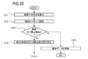
- FIG. 25 is a flow chart showing an example of the stationary object information identifying process in step S130 shown in FIG.
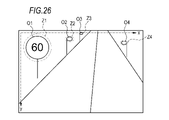
- FIG. 26 is a schematic diagram for explaining the stationary object position information indicating the stationary object position specified in step S134 shown in FIG.
- FIG. 27 is a flow chart showing another example of the stationary object information utilization method according to the fourth embodiment of the present disclosure.
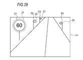
- FIG. 28 is an example of the light distribution information database shown in FIG.
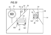
- FIG. 29 is a schematic diagram for explaining a light distribution pattern based on the light distribution information shown in FIG.
- FIG. 30 is a schematic diagram for explaining correction of the light distribution pattern shown in FIG.
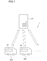
- FIG. 1 is a schematic diagram showing a system 1.
- the system 1 includes a stationary object information storage device 200 and a plurality of vehicles 2 such as vehicles 2A and 2B each having a stationary object information utilization device 300 mounted thereon.
- the stationary object information storage device 200 and each vehicle 2 can be communicatively connected to each other by wireless communication.
- the vehicle 2 may further include a stationary object information acquisition device (not shown).
- the stationary object information acquisition device acquires stationary object information about a stationary object and transmits the stationary object information to the stationary object information storage device 200 .
- the stationary object information storage device 200 stores, for example, stationary object information received from each stationary object information acquisition device. Further, the stationary object information storage device 200 analyzes the received stationary object information, for example, improves the accuracy of the stationary object information, acquires more detailed information, and creates a light distribution pattern based on the stationary object information. Create.
- the stationary object information storage device 200 also transmits the stationary object information with improved accuracy to each vehicle 2 in response to a request from each vehicle 2, for example.
- Stationary object information utilization apparatus 300 may be configured to function also as a stationary object information acquisition apparatus.
- the "stationary object” in the present embodiment refers to an object that is fixed to the road and has a high brightness, and specifically includes a self-luminous body (for example, a street light, a traffic signal, etc.), a sign, a delineator, and guardrails. That is, the stationary object information acquiring apparatus according to the present embodiment acquires stationary object information related to the various stationary objects given as specific examples above. As another embodiment, the stationary object information acquisition device detects an object that is not included in the above specific examples, but is fixed to the road, has high brightness, and can affect target detection. It may be configured to be identifiable as
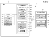
- FIG. 2 is a block diagram showing the system 1 according to the first embodiment of the present disclosure.
- the vehicle 2 includes a vehicle ECU (Electronic Control Unit) 10, a storage unit 20, a sensor unit 31, a position information acquisition unit 32, an illuminance sensor 33, a lamp ECU 40, and a stationary object information utilization device 300. ing.
- the vehicle 2 can communicate with the stationary object information storage device 200 by wireless communication via the communication network 3 .
- the means of wireless communication is not particularly limited, and for example, mobile communication systems such as telematics for automobiles, cooperation with smartphones, utilization of in-vehicle Wi-Fi, etc. may be used.
- the vehicle ECU 10 controls various operations such as running of the vehicle 2 .
- the vehicle ECU 10 includes, for example, a processor such as an ASIC (Application Specific Integrated Circuit), an FPGA (Field Programmable Gate Array), or a general-purpose CPU (Central Processing Unit).
- the storage unit 20 includes, for example, a ROM (Read Only Memory) storing various vehicle control programs and a RAM (Random Access Memory) temporarily storing various vehicle control data.
- the processor of the vehicle ECU 10 develops data designated by various vehicle control programs stored in the ROM onto the RAM, and controls various operations of the vehicle 2 in cooperation with the RAM.
- the sensor unit 31 outputs image data of an image of the exterior of the vehicle 2.
- the sensor unit 31 includes, for example, one or more sensors of a visible camera, LiDAR, and millimeter wave radar. Image data output by LiDAR and millimeter wave radar can be three-dimensional image data.
- the position information acquisition unit 32 outputs vehicle position information indicating the current position of the vehicle 2 .
- the position information acquisition unit 32 includes, for example, a GPS (Global Positioning System) sensor.
- the illuminance sensor 33 detects and outputs the illuminance around the vehicle 2 .
- the stationary object information utilization device 300 includes a control section 310 and a storage section 320 .
- the control unit 310 is configured by, for example, a processor such as a CPU.
- the control unit 310 can be configured as a part of the lamp ECU 40, for example. Further, the control unit 310 may be configured as a part of the vehicle ECU 10, for example.
- the storage unit 320 is configured by, for example, a ROM, a RAM, or the like.
- the storage unit 320 may be configured as part of a storage device provided for the storage unit 20 or the lamp ECU 40 .
- the control unit 310 controls the location information acquisition unit 331, the transmission/reception unit 332, the stationary object information acquisition unit 333, the image acquisition unit 334, the stationary object detection unit 335, and the mobile unit. It functions as the detection unit 336 . Note that part of these functions may be realized by the vehicle ECU 10 or the lamp ECU 40 . In such a configuration, the vehicle ECU 10 or the lamp ECU 40 forms part of the stationary object information utilization apparatus 300 . Also, the program 321 may be recorded on a non-temporary computer-readable medium.
- the location information acquisition unit 331 acquires location information that specifies at least one of the current location information of the vehicle 2, the destination information, the planned travel route information, and the home point information of the user of the vehicle 2.
- the location information can be obtained from a navigation system (not shown) mounted on the vehicle 2 or the position information obtaining section 32, for example.
- the vehicle ECU may intervene in the acquisition of the location information.
- the transmitting/receiving unit 332 selects between an image in which a still object exists or still object image data corresponding to a portion of the image, and still object position information indicating the position of the still object calculated based on the still object image data.
- a stationary object database 222 in which stationary object information 323 including at least one of them and imaging position information (vehicle position information at the time of imaging) 324 indicating the imaging position at which the still object image data was captured are recorded in association with each other. From the provided stationary object information storage device 200, the stationary object information and the imaging position information associated with each other are received by wireless communication.
- the transmitting/receiving unit 332 also transmits and receives other information to and from the vehicle ECU 10, the lamp ECU 40, and the stationary object information storage device 200 as necessary. That is, the transmitting/receiving section 332 functions as a transmitting section and a receiving section.
- the stationary object information acquisition unit 333 acquires information recorded in the stationary object database 222 , that is, the stationary object information 323 and the imaging position information 324 that are associated with each other, via the transmission/reception unit 332 .
- the stationary object information 323 acquired by the stationary object information acquiring unit 333 preferably includes at least one type of information of the type and size of the stationary object as the detailed information of the stationary object.
- the stationary object information acquisition unit 333 may be configured to acquire reference image data recorded in the stationary object database 222 .
- the reference image data is still object image data captured during the daytime.
- the reference image data is the image data 122 captured when the illuminance is equal to or higher than a predetermined value (for example, 1000 lux).
- the stationary object information acquisition unit 333 captures the stationary object information 323 corresponding to the location included in the location information acquired by the location information acquisition unit 331 or an area within a predetermined distance range (for example, within 1 km) from the location.
- Location information 324 is preferably obtained.
- the image acquisition unit 334 acquires the image data 322 of the current image (hereinafter also referred to as “current image”) captured by the sensor unit 31 when the vehicle 2 passes through the imaging position indicated by the imaging position information 324. .
- the stationary object detection unit 335 detects a stationary object at the imaging position indicated by the imaging position information 324 based on the stationary object information 323 and the imaging position information 324 . It is preferable that the stationary object detection unit 335 detects a stationary object in the current image based on the stationary object information 323 and the imaging position information 324 and the current image acquired by the image acquisition unit 334 . For example, the stationary object detection unit 335 may detect a stationary object by determining whether or not there is a stationary object at a position corresponding to the stationary object position indicated by the stationary object information 323 in the current image. The stationary object detection unit 335 may detect a stationary object based on a comparison between the reference image corresponding to the reference image data and the current image.
- the stationary object detection unit 335 can detect stationary objects by, for example, detecting light spots from the image or performing pattern recognition processing on the image.
- a conventionally known technique can be used for the detection of the light spot, and for example, it can be performed by luminance analysis of the image.
- a conventionally known method can be used as a pattern recognition method.
- a machine learning model may be used to detect a stationary object, or a clustering method may be used to detect a stationary object.
- the stationary object detection unit 335 335 detects stationary objects based on the current image. Note that when the position where the stationary object is estimated to exist based on the stationary object information 323 and the position where the stationary object is estimated to exist based on the current image are different, the transmitting/receiving unit 332 transmits the image data of the image. , to the stationary object information storage device 200 having the stationary object database 222 .
- the moving body detection unit 336 detects a moving body based on the current image.
- the moving object detection unit 336 detects, for example, an area in the current image other than the position corresponding to the position of the stationary object indicated by the stationary object information 323 and an area corresponding to the position of the stationary object where it is determined that there is no stationary object. may be targeted to detect a moving object. That is, when the stationary object detection unit 335 detects a stationary object in the current image at a position where the stationary object is estimated to exist based on the stationary object information 323, the moving object detection unit 336 detects the detected stationary object in the current image. The presence or absence of a moving object may be determined in an area excluding stationary objects. As with the stationary object detection unit 335, the moving object detection unit 336 may detect a moving object by performing light spot detection and pattern recognition processing. The moving object detection unit 336 may detect moving objects using other known techniques.
- control unit 310 serves as a light distribution unit that controls the light distribution of the headlights when the vehicle 2 passes through the imaging position indicated by the imaging position information 324 based on the stationary object information 323 and the imaging position information 324.
- the light distribution unit determines a first light distribution pattern based on the position of the stationary object detected by the stationary object detection unit 335 and the position of the moving object detected by the moving object detection unit 336.
- a third light distribution pattern may be generated by adding the second light distribution pattern, and the light distribution may be controlled based on the third light distribution pattern.
- the first light distribution pattern is, for example, a light distribution pattern created so as to be suitable for the position of a stationary object in the current image.
- the second light distribution pattern includes, for example, a light distribution instruction for the position of the moving object in the current image.
- the third light distribution pattern is, for example, obtained by adding the second light distribution pattern to the first light distribution pattern. More specifically, the third light distribution pattern may be obtained by overwriting the first light distribution pattern with the second light distribution pattern in the area where the moving object is located.
- the stationary object acquisition device acquires image data of an image captured by the sensor unit 31, for example.
- the still object acquisition device includes, for example, an image in which a still object exists or still object image data corresponding to a part of the image, and still object position information indicating the position of the still object calculated based on the image data;
- the stationary object information including at least one of is specified based on the image data.
- the stationary object information is specified, for example, by detecting light spots from the image or by subjecting the image to pattern recognition processing.
- a conventionally known technique can be used for the detection of the light spot, and for example, it can be performed by luminance analysis of the image.
- a conventionally known method can be used as a pattern recognition method.
- a machine learning model may be used to detect a stationary object, or a clustering method may be used to detect a stationary object.
- the stationary object acquisition device transmits, for example, stationary object information and vehicle position information when an image in which the stationary object information is specified is captured to the stationary object information storage device 200 .
- the stationary object information storage device 200 includes a control section 210 and a storage section 220 .
- the stationary object information storage device 200 is a computer device that aggregates and accumulates information transmitted from a plurality of vehicles 2, and is installed in a data center, for example.
- the control unit 210 is configured by, for example, a processor such as a CPU.
- the storage unit 220 is configured by, for example, a ROM, a RAM, or the like.
- the control unit 210 functions as the transmission/reception unit 211 by reading the program 221 stored in the storage unit 220 .
- the program 221 may be recorded on a non-temporary computer-readable medium.
- the transmission/reception unit 211 transmits and receives information to and from the vehicle ECU 10 and the stationary object information utilization device 300 . That is, the transmitting/receiving section 211 functions as a transmitting section and a receiving section.
- the transmitting/receiving unit 211 transmits the still object information 323 (which may include reference image data) recorded in the still object database 222 and the imaging position information 324 associated with the still object information 323 to the still object information utilization apparatus 300.
- the transmission/reception unit 211 receives, for example, stationary object information and imaging position information associated with the stationary object information from the stationary object information acquisition device. .
- the control unit 210 can also function as a recording unit that records each piece of information received from the stationary object information acquisition device in the stationary object database 222 . Further, the control unit 210 can execute, for example, a process of determining whether the stationary object information received from the stationary object information acquisition device is correct or an error, and a process of specifying detailed information.
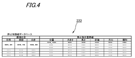
- Imaging position information (vehicle position information) 324 and stationary object information 323 are associated and recorded in the stationary object database 222 .
- the stationary object database 222 for example, a plurality of pieces of stationary object image data can be recorded for one imaging position indicated by the vehicle position information 324 .
- stationary object image data and reference image data having the same imaging position can be associated and recorded.
- detailed information such as the position and size of the stationary object, the distance and direction from the imaging position, and the type of the stationary object can be recorded in association with the imaging position.
- the stationary object database 222 records a plurality of pieces of still object image data and reference image data in association with imaging positions.
- the imaging position the latitude and longitude of the imaging position and the orientation of the vehicle 2 at the time of imaging (for example, the orientation of the visible camera) are recorded.
- the stationary object image data an ID for identifying the stationary object image data, time information, illuminance information, and lighting information are recorded.
- An ID for identification is recorded in the reference image data.
- the reference image data may further include information similar to that of the still object image data.
- Still object image data whose illuminance indicated by the illuminance information is equal to or greater than a predetermined value may be treated as reference image data.
- the stationary object database 222 records a plurality of pieces of stationary object position information in association with the imaging position.
- the stationary object position information detailed information such as the stationary object position, size, height, distance and direction from the imaging position, and stationary object type is recorded. Note that when only one stationary object is identified at a certain imaging position, one piece of stationary object position information can be associated with that imaging position.
- the stationary object position can be identified using, for example, an arbitrary coordinate system set in the image.
- the stationary object position may indicate, for example, the center point of the stationary object or the position of the outer edge of the stationary object.
- the position of the stationary object preferably includes information about the size specified using the coordinate system.
- the stationary object position may indicate the distance and direction from the imaging position of the image to the stationary object.
- the distance and direction from the imaging position to the stationary object may be calculated using the depth information. Further, it may be calculated by comparison with other image data captured near the imaging position, or may be calculated using data obtained from millimeter wave radar or LiDAR.
- FIGS. 3 and 4 show an example of information recorded in the stationary object database 222, and some information may not be recorded, and other information may be included. From the viewpoint of increasing the accuracy of the determination process described above by the control unit 210 and increasing the utility value of the still object database 222, the still object database 222 should include both still object image data and still object position information. is preferred.
- the stationary object database 222 may be managed as an individual database for each vehicle 2, for example. In this case, information accumulated in one database is based on information transmitted from one vehicle 2 . Also, the stationary object database 222 may be managed as a database of the entire plurality of vehicles 2, for example. In this case, multiple pieces of information transmitted from multiple vehicles 2 are aggregated in one database.
- the stationary object database 222 may be managed as a database for each model of the vehicle 2, for example.
- a plurality of pieces of information transmitted from a plurality of vehicles 2 of the same vehicle type are aggregated.
- the stationary object information storage device 200 receives the stationary object information and the like from the stationary object acquisition device, the model information of the vehicle 2 is also received. It may be configured to record vehicle type information.
- the stationary object information storage device 200 may be mounted on the vehicle 2.
- control unit 210 and storage unit 220 may be provided separately from vehicle ECU 10 , control unit 310 , storage unit 20 , and storage unit 320 .
- the control unit 210 may be configured as a part of any one or more of the lamp ECU 40, the vehicle ECU 10, and the control unit 310, for example.
- part of the functions of the control unit 210 may be implemented by the vehicle ECU 10 or the lamp ECU 40 .
- the storage unit 220 may be configured as a part of one or more of the storage unit 20, the storage unit 320, or a storage device provided for the lamp ECU 40, for example.
- the stationary object information storage device 200 is installed in the vehicle 2, the stationary object information utilization device 300 and the stationary object information storage device 200 are configured to be connectable by wireless communication or wired communication.
- the static object information utilization method is executed by, for example, the control unit 310 of the static object information utilization device 300 loaded with the program 321 and the control unit 210 of the static object information storage device 200 loaded with the program 221. .
- the still object information utilization device 300 detects a stationary object or the like using the still object information 323 and the current image captured by the visible camera will be described as an example. It is not limited to this.
- the stationary object information utilization apparatus 300 may detect a stationary object or the like, for example, using the stationary object information 323 and the current image output by the millimeter wave radar or LiDAR.
- FIG. 5 is a flowchart showing an example of a stationary object information utilization method according to this embodiment. It should be noted that the order of each process constituting each flowchart described in this specification may be random as long as there is no contradiction or inconsistency in the contents of the process, and the processes may be executed in parallel.
- step S301 the control unit 310 acquires at least one or more location information out of the current location information of the vehicle 2, the destination information, the planned travel route information, and the home location information of the user of the vehicle 2.
- step S302 the control unit 310 transmits the stationary object information 323 and the imaging position information 324 corresponding to the location included in the location information acquired in step S301 or an area within a predetermined distance range from the location. is requested to the stationary object information storage device 200 .
- Step S302 may be executed, for example, based on the operation of the user of the vehicle 2, or when the vehicle 2 is activated at a predetermined timing (for example, when the engine of the vehicle 2 is started, or when the planned travel route of the vehicle 2 is determined). , when the vehicle 2 is stopped or slowed down, when the program 121 is updated, etc.).
- FIG. 6 is a schematic diagram for explaining the area for acquiring the location information and the stationary object information 323 acquired by the control unit 310.
- a current location (start point) A1, a destination A2, a planned travel route R, and an area Q are shown on the map.
- a current position A1 indicates the current position of the vehicle 2 .
- Destination A2 indicates, for example, the destination of vehicle 2 entered into the navigation system by the user of vehicle 2 .
- the planned travel route R indicates a route from the current location A1 to the destination A2, which is calculated by the navigation system and selected by the user of the vehicle 2, for example. Information about these points and routes can be obtained from, for example, a navigation system.
- the area Q is an area within a predetermined distance range from the current location A1, the destination A2, and the planned travel route R.
- the predetermined distance range may be set by the user.
- home point information indicating the home point (not shown) of the user of the vehicle 2 may be acquired as the location information, and the region Q may include a predetermined distance range from the home point.
- the predetermined distance range may be different for one or more of the current location A1, the destination A2, the planned travel route R, and the home location.
- the region Q may be set by making the distance range from the home point larger than the distance range from the planned travel route R or the like.
- the stationary object information 323 of the place where the passage frequency or the possibility of being passed is high can be acquired. becomes possible. Moreover, as a result, an increase in the amount of communication and an increase in the size of the storage unit 320 can be suppressed.
- step S303 the control unit 210 converts the still object information 323 and the imaging position information 324 indicating the imaging position associated with the still object information 323 into the stationary object information. It transmits to the utilization device 300 . From the viewpoint of increasing the range of utilization of the stationary object information 323 in the vehicle 2 and improving the detection accuracy of the stationary object, in step S303, the reference image data at the imaging position and the detailed information of the stationary object are also transmitted. preferably.
- step S ⁇ b>303 the control unit 210 transmits the stationary object information 323 and the imaging position information 324 indicating the imaging position associated with the stationary object information 323 to the stationary object information utilization device 300 .
- the reference image data at the imaging position and the detailed information of the stationary object are also transmitted. preferably.
- step S304 the control unit 310 receives each piece of information transmitted in step S303.
- step S ⁇ b>305 the control unit 310 acquires the current image captured by the visible camera when the vehicle 2 passes through the imaging position indicated by the imaging position information 324 .
- step S306 the control unit 310 detects a stationary object from the current image, for example, based on the stationary object information 323 and the current image. In step S306, for example, it is determined whether or not a stationary object exists in the current image at the position indicated by the stationary object information 323 (the position where the stationary object is estimated to exist based on the stationary object information 323).
- the control unit 310 detects the presence or absence of a moving object in the area excluding the detected stationary object, and terminates.
- the detected position of a stationary object and the position of a moving object can be used, for example, for light distribution control of headlights, target detection in automatic driving, and the like.
- control unit 310 detects a position indicated by stationary object information 323 where no stationary object is detected. The presence or absence of a moving object is detected in an area including . Further, in step S ⁇ b>309 , control unit 310 transmits image data of the current image and imaging position information 324 of the current image to stationary object information storage device 200 . Note that even if a stationary object is detected at a position other than the position indicated by the stationary object information 323 in step S306, the processing from step S309 onward can be performed.
- step S310 the control unit 210 receives each piece of information transmitted at step S309.
- step S311 the control unit 210 updates the stationary object database 222 so that the information received in step S310 is included in the stationary object database 222, and ends the process.
- the control unit 210 may specify the position of the still object in the current image data based on the current image data received in step S309 and the still object information 323 recorded in the still object database. In this case, it is preferable to use an algorithm different from the processing of step S306 and with higher accuracy.
- step S309 As a result of this identification, if it is determined that the stationary object information 323 recorded in the stationary object database 222 is correct and the detection result in step S306 is incorrect, each piece of information transmitted in step S309 may be deleted. By executing a series of processes after step S309, it is possible to further improve the accuracy of the stationary object information 323 recorded in the stationary object database 222.
- FIG. 7 is a schematic diagram for explaining the positions of stationary objects indicated by the stationary object information 323 shown in FIG.
- FIG. 8 is a schematic diagram for explaining the stationary object detection processing in step S306.
- FIG. 9 is a schematic diagram for explaining the moving object detection processing in step S308.
- the stationary object information 323 acquired from the stationary object information storage device 200 includes information that stationary objects are present in the areas Z1 to Z4.
- the stationary object information 323 includes information regarding the position of the stationary object defined using the coordinates defined by the x-axis and the y-axis.
- step S306 it is determined whether or not there is a stationary object in the areas Z1 to Z4 using techniques such as light spot detection and pattern recognition processing.
- stationary objects O1 to O4 are detected in areas Z1 to Z4, respectively. Therefore, in step S307, moving object detection processing is performed on areas other than the areas Z1 to Z4. By configuring in this way, it is possible to reduce the area where the moving object detection processing is performed, so that the processing load on the control unit 310 can be reduced.
- other vehicles C1 and C2 are detected as moving objects.
- the other vehicle C1 is detected based on the light spots of the rear lamps BL1 and BL2, for example.
- another vehicle C2 is detected, for example, based on light spots such as headlights HL1 and HL2.
- the detection of a stationary object is not particularly limited, but for example, from the viewpoint of reducing the processing load, it is performed depending on whether or not a light spot that is estimated to be a stationary object is detected in each of the regions Z1 to Z4. good too. Further, when the stationary object information 323 is not used, even if a light spot is detected, the load on the control unit 310 can be reduced by determining whether it is caused by a stationary object or a moving object. They may grow up or make mistakes in judgment. For example, if the distance between two stationary objects is approximately the same as the distance between left and right lamps of a car, the two stationary objects may be erroneously determined to be moving objects. On the other hand, by using the stationary object information 323, it can be estimated that the light spot existing at the position of the stationary object indicated by the stationary object information 323 is caused by the stationary object. It is expected that the accuracy of determination of stationary objects will be improved.
- regions Z1 to Z4 are superimposed on a current image CI2 different from the current image CI1.
- stationary objects O1 to O2 and O4 are detected in areas Z1 to Z2 and Z4, respectively, but no stationary object is detected in area Z3.
- moving object detection processing is performed on areas other than the areas Z1 to Z2 and Z4.
- the area Z3 is the target of the moving object detection processing.
- the image data of the current image CI2 is transmitted to the still object information storage device 200.
- FIG. In the stationary object information storage device 200 for example, whether or not a stationary object really exists in the area Z3 of the current image CI2 can be determined by an algorithm different from that in step S306.
- stationary objects may be detected in addition to areas other than the areas Z1 to Z4.
- the control unit 310 determines that the stationary object exists in the other area.
- the current images CI1 and CI2 are transmitted to the stationary object information storage device 200.
- FIG. in the still object information storage device 200 for example, whether or not a still object really exists in other areas of the current images CI1 and CI2 can be determined by an algorithm different from that in step S306.
- the stationary object information utilization device 301 according to the second embodiment of the present disclosure will be described.
- Components of the stationary object information utilization device 301 are the same as those of the stationary object information utilization device 300 according to the first embodiment, except for the configurations described below, and the same reference numerals are used.
- FIG. 10 is a schematic diagram showing an example of the system 1 including the stationary object information utilization device 301 according to the second embodiment of the present disclosure.
- the stationary object information utilization device 301 is mounted on the vehicle 2 included in the system 1, as shown in FIG.
- FIG. 11 is a block diagram showing an example of the system 1 shown in FIG.
- the vehicle 2 includes a vehicle ECU 10 , a storage unit 20 , a sensor unit 31 , a position information acquisition unit 32 , an illuminance sensor 33 , a lamp ECU 40 and a stationary object information utilization device 301 .
- the stationary object information utilization device 301 includes a control section 310 and a storage section 320 .
- the control unit 310 controls the transmission/reception unit 332, the stationary object information acquisition unit 333, the image acquisition unit 334, the stationary object detection unit 335, the moving object detection unit 336, and the light distribution unit. 337 , regression analysis unit 338 , and vehicle information acquisition unit 339 . Note that part of these functions may be realized by the vehicle ECU 10 or the lamp ECU 40 .
- the transmitting/receiving section 332 functions as a transmitting section and a receiving section.
- the stationary object information acquiring unit 333 acquires information recorded in the stationary object database 222 , that is, the stationary object information 323 and the imaging position information 324 that are associated with each other, via the transmitting/receiving unit 332 .
- the stationary object information 323 acquired by the stationary object information acquisition unit 333 includes at least information on the type and size of the stationary object and the image intensity of the position of the stationary object in the stationary object image data as the detailed information on the stationary object. Preferably, one or more types of information are included.
- the stationary object information acquisition unit 333 may be configured to acquire reference image data recorded in the stationary object database 222 .
- the light distribution unit 337 controls the light distribution of the headlights when the vehicle 2 passes through the imaging position indicated by the imaging position information 324 based on the stationary object information 323 and the imaging position information 324 .
- the light distribution unit 337 further distributes the light based on the detailed information including at least one of information on the type and size of the stationary object, and information on the image intensity of the position of the stationary object in the stationary object image data. may be controlled.
- the light distribution unit 337 detects the first light distribution pattern based on the position of the stationary object detected by the stationary object detection unit 335, and the position of the moving object detected by the moving object detection unit 336.
- a third light distribution pattern is generated by adding the determined second light distribution pattern, and the light distribution is controlled based on the third light distribution pattern.
- the first light distribution pattern is, for example, a light distribution pattern created to be suitable for the position of a stationary object in the current image.
- the second light distribution pattern includes, for example, a light distribution instruction for the position of the moving object in the current image.
- the third light distribution pattern is, for example, obtained by adding the second light distribution pattern to the first light distribution pattern. More specifically, the third light distribution pattern may be obtained by overwriting the first light distribution pattern with the second light distribution pattern in the area where the moving object is located.
- the light distribution unit 337 determines that the vehicle 2 passes through the first imaging position and the distance to the second imaging position that the vehicle is scheduled to pass next satisfies a predetermined condition (for example, within 10 m). is satisfied, light distribution can be controlled. Moreover, the light distribution unit 337 may further control light distribution based on vehicle information acquired by the vehicle information acquisition unit 339 .
- the light distribution unit 337 can control one or more of light distribution for low beam and light distribution for high beam. Also, the light distribution unit 337 may output light distribution information defining a light distribution pattern to the lamp ECU.
- the light distribution information may be information in any format, for example, information on one or more of gradation values, current values, and light shielding angles for a plurality of light sources included in the headlamp. Alternatively, image data representing a light distribution pattern may be used.
- the regression analysis unit 338 performs the first Based on the first stationary object information 323 corresponding to the imaging position of and the second stationary object information 323 corresponding to the second imaging position, stillness between the first imaging position and the second imaging position Object positions are calculated by regression analysis.
- the method of regression analysis is not particularly limited, and conventionally known methods can be used.
- One example of regression analysis is linear interpolation.
- the regression analysis unit 338 may further calculate the position of a stationary object between the first imaging position and the second imaging position based on the position of the road and the direction in which the road extends at each imaging position. good.
- the regression analysis unit 338 may also calculate the positions of the stationary objects between the imaging positions based on the stationary object information 323 at three or more imaging positions where the distance between the imaging positions satisfies a predetermined condition.
- the vehicle information acquisition unit 339 acquires vehicle information including at least one type of information among the direction in which the vehicle 2 is facing and the position in the vehicle width direction in the driving lane.
- the position in the vehicle width direction in the driving lane can be calculated, for example, based on the position of the driving lane in the current image.
- the direction in which the vehicle 2 is facing can be calculated based on the transition of the vehicle position information output by the position information acquisition unit 32, for example.
- the vehicle information acquisition unit 339 may further acquire information about the steering angle of the steering wheel that can be acquired from the vehicle ECU 10 .
- the stationary object information storage device 200 includes a control section 210 and a storage section 220 .
- the control unit 210 functions as a transmission/reception unit 211 by reading a program 221 stored in the storage unit 220 .
- Imaging position information (vehicle position information) 324 and stationary object information 323 are associated and recorded in the stationary object database 222 .
- the stationary object database 222 for example, a plurality of pieces of stationary object image data can be recorded for one imaging position indicated by the vehicle position information 324 . Further, in the stationary object database 222, stationary object image data and reference image data having the same imaging position can be associated and recorded.
- the stationary object database 222 In the stationary object database 222, detailed information such as the position and size of the stationary object, the distance and direction from the imaging position, the type of the stationary object, and the image intensity of the position of the stationary object in the still object image is stored at the imaging position. can be recorded in association.
- a plurality of still object image data and reference image data are recorded in the stationary object database 222 in association with the imaging position.
- the imaging position the latitude and longitude of the imaging position and the orientation of the vehicle 2 at the time of imaging (for example, the orientation of the visible camera) are recorded.
- the stationary object image data an ID for identifying the stationary object image data, time information, illuminance information, and lighting information are recorded.
- An ID for identification is recorded in the reference image data.
- the reference image data may further include information similar to that of the still object image data.
- Still object image data whose illuminance indicated by the illuminance information is equal to or greater than a predetermined value may be treated as reference image data.
- the stationary object database 222 records a plurality of pieces of stationary object position information in association with the imaging position.
- the stationary object position information detailed information such as the position of the stationary object, size, height, distance and direction from the imaging position, type of the stationary object, and image intensity of the position of the stationary object in the still object image is recorded. . Note that when only one stationary object is identified at a certain imaging position, one piece of stationary object position information can be associated with that imaging position.
- the static object information utilization method is executed by, for example, the control unit 310 of the static object information utilization device 301 loaded with the program 321 and the control unit 210 of the static object information storage device 200 loaded with the program 221. .
- the still object information utilization device 301 controls the light distribution using the still object information 323 and the current image captured by the visible camera as an example.
- the stationary object information utilization device 301 may control light distribution using, for example, the stationary object information 323 and the current image output by the millimeter wave radar or LiDAR.
- FIG. 12 is a flow chart showing an example of a method for using stationary object information according to this embodiment. It should be noted that the order of each process constituting each flowchart described in this specification may be random as long as there is no contradiction or inconsistency in the contents of the process, and the processes may be executed in parallel.
- step S411 the control unit 310 requests the stationary object information storage device 200 to transmit the stationary object information 323 at a predetermined imaging position.
- Step S411 may be executed, for example, based on the operation of the user of the vehicle 2, or when the vehicle 2 is operated at a predetermined timing (for example, when the engine of the vehicle 2 is started, when the planned travel route of the vehicle 2 is determined). , when the vehicle 2 is stopped or slowed down, when the program 121 is updated, etc.).
- the predetermined imaging position is not particularly limited, for example, from the viewpoint of high usability for the user of the vehicle 2, the current value of the vehicle 2, the destination, the planned travel route, and the home of the user of the vehicle 2 A position within a predetermined distance range is preferable.
- the control unit 210 Upon receiving the request from the still object information utilization apparatus 301, in step S412, the control unit 210 converts the still object information 323 and the imaging position information 324 indicating the imaging position associated with the still object information 323 into the stationary object information. It transmits to the utilization device 301 . From the viewpoint of realizing a more suitable light distribution, it is preferable to transmit the reference image data and the detailed information of the stationary object at the imaging position in step S412.
- step S413 the control unit 310 receives each piece of information transmitted in step S412.
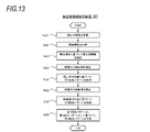
- step S414 the control unit 310 generates a light distribution pattern of the headlights at the imaging position indicated by the imaging position information 324 associated with the stationary object information 323 based on the stationary object information 323 and the like, and ends the process. do.
- FIG. 13 is a flowchart showing an example of light distribution pattern generation processing in step S414 shown in FIG. First, in step S ⁇ b>421 , the control unit 310 acquires the current image captured by the visible camera when the vehicle 2 passes the imaging position indicated by the imaging position information 324 .
- step S422 the control unit 310 acquires vehicle information.
- the vehicle information may be the direction in which the vehicle 2 is facing, the position in the vehicle width direction in the driving lane of the vehicle 2, or both of them.
- step S422 information regarding the steering angle of the steering wheel may be obtained.
- step S423 the control unit 310 corrects the stationary object information 323 based on the vehicle information acquired in step S422.
- the stationary object information 323 specifies a stationary object based on the image captured at that imaging position. Therefore, depending on the direction in which the vehicle 2 is facing or the position in the vehicle width direction, the position of the stationary object indicated by the stationary object information 323 may deviate from the position of the stationary object in the current image. Therefore, by performing the processing of step S423, the above deviation can be eliminated, and the accuracy of detecting a stationary object in the current image, which will be described later, can be improved. It should be noted that if there is little deviation as described above, the process of step S423 may not be executed.
- the stationary object information 323 may not be used in generating the light distribution pattern. good.
- the position of the stationary object in the current image and the position of the stationary object indicated by the stationary object information 323 are greatly displaced. is not expected.
- step S424 the control unit 310 detects a stationary object from the current image based on the stationary object information 323 corrected in step S423.
- step S425 control unit 310 generates a first light distribution pattern based on the position of the stationary object detected in step S424.
- the light distribution information defining the first light distribution pattern may be stored in the storage unit 320, and the first light distribution pattern may be reused when passing through that position again next time.
- the first light distribution pattern includes at least one type of detailed information among the size and type of the stationary object, and the image intensity of the position of the stationary object in the still object image data. It is preferably made on the basis of The first light distribution pattern is obtained by, for example, dimming the position of a stationary object with reference to a normal light distribution pattern for low beam or high beam.
- the user of the vehicle 2 may feel dazzled by the reflected light from the stationary object. is preferably dimmed.
- the light may be distributed as normal for a stationary object for which the reflected light is not a problem.
- whether or not the object is a high-brightness reflecting object may be determined based on information regarding the type of the stationary object and the image intensity of the position of the stationary object in the still object image.
- the information about the image intensity may be, for example, the gradation value of the image.
- the stationary object may be determined as a high-brightness reflecting object.
- the stationary object may be determined as the high-brightness reflecting object.
- control unit 310 detects a moving object from the current image.
- control unit 310 generates a second light distribution pattern based on the position of the moving object detected in step S426.
- control unit 310 generates a third light distribution pattern based on the first light distribution pattern and the second light distribution pattern.
- the control unit 310 outputs light distribution information defining the third light distribution pattern to the headlamp or the lighting ECU 40 or the like, so that the headlamp is controlled to distribute light based on the third light distribution pattern.
- the stationary object information 323 acquired from the stationary object information storage device 200 includes information that stationary objects are present in the areas Z1 to Z4.
- the first light distribution pattern is, for example, a normal light distribution pattern with dimming for the regions Z1 to Z4 added.
- the areas in which no stationary object is detected are not dimmed.
- the object of the moving object detection processing is, for example, the areas other than the areas Z1 to Z4.
- the second light distribution pattern is, for example, one that dims or shades the regions Z5 and Z6.
- the third light distribution pattern is obtained by adding dimming to the regions Z1 to Z4 and dimming or blocking to the regions Z5 to Z6 in the normal light distribution pattern.
- priority may be given to light reduction or light shielding for the area of the moving object.
- the other vehicle C1 is detected, for example, based on the light spots of the rear lamps BL1 and BL2.
- another vehicle C2 is detected, for example, based on light spots such as headlights HL1 and HL2.
- stationary object information 323 that has been acquired in advance is used to detect stationary objects and moving objects. The required time and load can be reduced.
- FIG. 14 is a schematic diagram showing positions of stationary objects when the vehicle 2 passes through the first imaging position.
- FIG. 15 is a schematic diagram showing the positions of stationary objects when the vehicle 2 passes through the second imaging position.
- the second imaging position is, for example, a position within 10 m from the first imaging position.
- the second imaging position is, for example, a position where the vehicle 2 has advanced without changing the traveling direction from the first imaging position.
- the stationary object information 323 includes information about the position of the stationary object defined using the coordinates defined by the x-axis and the y-axis.
- FIG. 14 shows that stationary objects O11 and O12 are present at the positions shown in the figure at the first imaging position. Further, in the example of FIG. 15, the relative positions of the stationary objects O11 and O12 with respect to the vehicle 2 change due to the forward movement of the vehicle 2, and the stationary objects O11′ and O12′ are present. is shown.
- the control unit 310 calculates the position of the stationary object 11 assuming that the stationary object 11 apparently moves within the region Z11 between the first imaging position and the second imaging position, and the calculation result is Based on this, for example, each process of steps S424 to S428 is executed. Similarly, after passing the second imaging position, the position of the stationary object 11 can be calculated assuming that the stationary object 11 apparently moves within the area Z11. Similarly, the stationary object 12 and the stationary object O12' are considered to apparently move within the region Z12 extending so as to connect the stationary object 12 and the stationary object O12'.
- each configuration of the stationary object information utilization device 302 is the same as each configuration of the stationary object information utilization device 300 according to the first embodiment, and the same reference numerals are used.
- FIG. 16 is a schematic diagram showing an example of the system 1 including the stationary object information utilization device 302 according to the third embodiment of the present disclosure.
- the stationary object information utilization device 302 is mounted on the vehicle 2 included in the system 1, as shown in FIG.
- FIG. 17 is a block diagram showing an example of the system 1 shown in FIG.
- the vehicle 2 includes a vehicle ECU 10 , a storage unit 20 , a sensor unit 31 , a position information acquisition unit 32 , an illuminance sensor 33 , a lamp ECU 40 and a stationary object information utilization device 302 .
- the stationary object information utilization device 302 includes a control section 310 and a storage section 320 .
- the control unit 310 controls the transmission/reception unit 311 , the stationary object information acquisition unit 312 , the image acquisition unit 313 , the stationary object region identification unit 314 , the detection condition determination unit 315 , and the interest detection unit 315 . It functions as the area specifying unit 316 . Note that part of these functions may be realized by the vehicle ECU 10 or the lamp ECU 40 .
- the transmitting/receiving unit 311 functions as a transmitting unit and a receiving unit.
- the stationary object information acquisition unit 312 acquires information recorded in the stationary object database 222 , that is, the stationary object information 323 and the imaging position information 324 that are associated with each other, via the transmitting/receiving unit 311 .
- the stationary object information 323 acquired by the stationary object information acquiring unit 312 preferably includes at least one or more information of the type and size of the stationary object as the detailed information of the stationary object. Further, the stationary object information acquisition unit 312 may be configured to acquire reference image data recorded in the stationary object database 222 .
- the stationary object region identifying unit 314 identifies the current image captured by the sensor unit 31 when the vehicle 2 passes the position indicated by the imaging position information 324 associated with the stationary object information 323 and the stationary object information 323. to specify a stationary object region in which the stationary object exists in the current image. For example, the stationary object region identification unit 314 detects a stationary object region by determining whether or not there is a stationary object in the region corresponding to the position of the stationary object indicated by the stationary object information 323 in the current image. good. The stationary object region identifying section 314 may detect the stationary object region based on a comparison between the reference image corresponding to the reference image data and the current image.
- the stationary object region identifying unit 314 can identify the stationary object region by detecting a stationary object, for example, by detecting light spots from the image or performing pattern recognition processing on the image.
- the stationary object region identifying unit 314 Based on this, a stationary object is detected and a stationary object area is specified. Note that when the position where the stationary object is estimated to exist based on the stationary object information 323 and the position where the stationary object is estimated to exist based on the current image are different, the transmitting/receiving unit 311 transmits the image data of the image. , to the stationary object information storage device 200 having the stationary object database 222 .
- a detection condition determining unit 315 determines conditions for detecting a region of interest in the current image based on the stationary object region specified by the stationary object region specifying unit 314 .
- the area of interest is not particularly limited, but for example, there are moving objects such as other vehicles and pedestrians that are watched in ADAS (Advanced Driver-Assistance Systems) and AD (Autonomous Driving) It can be an area where ADAS (Advanced Driver-Assistance Systems) and AD (Autonomous Driving) It can be an area where
- the detection condition determination unit 315 determines the region below the straight line connecting the plurality of still object regions in the current image as the detection range of the region of interest. In addition, for example, the detection condition determination unit 315 performs detection processing of a region of interest in a region below a straight line connecting a plurality of stationary object regions in the current image more than the number of times of detection processing of a region of interest in a region above the straight line. The number of detection processing times of the region of interest may be determined so as to increase the number of times.
- the detection condition determination unit 315 may determine, for example, a masked image obtained by masking a still object region in the current image as a region of interest detection target. Further, when the stationary object information 323 includes information about the type of the stationary object, and when the plurality of stationary objects included in the current image are the same type of stationary objects, the detection condition determination unit 315 determines the same type of stationary object. A masked image obtained by masking a region formed to include a plurality of stationary objects may be determined as a region of interest detection target. Also, the range to be masked is preferably a range obtained by adding a predetermined margin to the stationary object area.
- the region-of-interest identifying unit 316 identifies the region of interest in the current image based on the detection conditions determined by the detection condition determining unit 315 .
- a technique for identifying the region of interest is not particularly limited, and conventionally known techniques can be used.
- the region-of-interest identifying unit 316 may identify the region of interest by detecting light spots from the current image or performing pattern recognition processing on the current image, similarly to the stationary object region-identifying unit 314 .
- the stationary object information utilization method is executed by, for example, the control unit 310 of the stationary object information utilization device 302 loaded with the program 321 and the control unit 210 of the stationary object information storage device 200 loaded with the program 221. .
- the still object information utilization device 302 included in the system 1 identifies the region of interest using the still object information 323 and the current image captured by the visible camera will be described as an example.
- the disclosure is not so limited.
- the stationary object information utilization apparatus 302 may specify the region of interest using, for example, the stationary object information 323 and the current image output by the millimeter wave radar or LiDAR.
- FIG. 18 is a flow chart showing an example of a method for using stationary object information according to this embodiment. It should be noted that the order of each process constituting each flowchart described in this specification may be random as long as there is no contradiction or inconsistency in the contents of the process, and the processes may be executed in parallel.
- step S10 the control unit 310 requests the stationary object information storage device 200 to transmit the stationary object information 323 at a predetermined imaging position.
- Step S10 may be executed, for example, based on the operation of the user of the vehicle 2, or when the vehicle 2 is operated at a predetermined timing (for example, when the engine of the vehicle 2 is started, when the planned travel route of the vehicle 2 is determined). , when the vehicle 2 is stopped or slowed down, when the program 121 is updated, etc.).
- the predetermined imaging position is not particularly limited, for example, from the viewpoint of high usability for the user of the vehicle 2, the current value of the vehicle 2, the destination, the planned travel route, and the home of the user of the vehicle 2 A position within a predetermined distance range is preferable.
- step S20 the control unit 210 converts the still object information 323 and the imaging position information 324 indicating the imaging position associated with the still object information 323 into the stationary object information. It transmits to the utilization device 302 . From the viewpoint of further increasing the accuracy of specifying the region of interest, it is preferable to transmit the reference image data at the imaging position and the detailed information on the type and size of the stationary object in step S20.
- step S30 the control unit 310 receives each piece of information transmitted in step S20.
- step S ⁇ b>40 the control unit 310 acquires the current image captured by the visible camera when the vehicle 2 passes through the imaging position indicated by the imaging position information 324 .
- step S50 the control unit 310 identifies a still object area in the current image based on the still object information 323 and the current image.
- step S60 the control unit 310 determines conditions for detecting the region of interest in the current image based on the still object information 323 and the current image, based on the still object region identified in step S50.
- step S70 the control unit 310 identifies a region of interest in the current image based on the detection conditions determined in step S60, and terminates.
- FIG. 19 is a schematic diagram for explaining an example of the stationary object area specifying process in step S50.
- FIG. 20 is a schematic diagram for explaining an example of conditions for detecting a region of interest in step S60.
- FIG. 21 is a schematic diagram for explaining another example of the region-of-interest detection conditions in step S60.
- the stationary object information 323 acquired from the stationary object information storage device 200 includes information that stationary objects are present in the areas Z1 to Z3.
- regions Z1 to Z3 are superimposed on the current image CI3.
- other vehicles C1 and C2 are shown in the current image CI3.
- step S50 it is determined whether or not there is a stationary object in the areas Z1 to Z3 using methods such as light spot detection and pattern recognition processing.
- a stationary object In the example of FIG. 19, stationary objects O1 to O3 are detected in areas Z1 to Z3, respectively. Therefore, in step S50, the areas Z1 to Z3 are identified as stationary object areas. Further, in step S50, detailed information such as the type and size of the stationary object may be used to specify the type and size of the stationary object existing in each stationary object region.
- the method of detecting a stationary object is not particularly limited, for example, from the viewpoint of reducing the processing load, it is possible to you can go Further, when the stationary object information 323 is not used, even if a light spot is detected, the load on the control unit 310 can be reduced by determining whether it is caused by a stationary object or a moving object. They may grow up or make mistakes in judgment. For example, if the distance between two stationary objects is approximately the same as the distance between left and right lamps of a car, the two stationary objects may be erroneously determined to be moving objects. On the other hand, by using the stationary object information 323, it can be estimated that the light spot existing at the position of the stationary object indicated by the stationary object information 323 is caused by the stationary object. It is expected that the accuracy of determination of stationary objects will be improved.
- a straight line L connecting areas Z1 to Z3 identified as stationary object areas is shown.
- the straight line L may be, for example, an approximate straight line based on the central points or the barycentric points of the regions Z1-Z3.
- the detection conditions are determined such that the lower region Ar1 below the straight line L is determined as the region of interest detection range, and the upper region Ar2 above the straight line L is not the region of interest detection range.
- the road is considered to exist in the area Ar1 below the straight line L connecting the areas Z1 to Z3 identified as stationary object areas.
- the area Ar2 above the straight line L does not include the road. Therefore, the region of interest (moving body) detection target is not set for the upper region Ar2, and only the lower region Ar1 where the road exists is set as the region of interest detection target, thereby significantly reducing the detection accuracy of the region of interest. It is possible to reduce the load on the control unit 310 without
- the straight line L preferably connects stationary object areas in which stationary objects of the same type exist. This is because stationary objects of the same type often have the same actual height, and there is a high probability that the lower area Ar1 includes the road.
- a straight line L is a line connecting stationary object areas between stationary objects located on the same side of the road (for example, stationary objects located on the right side of the road or stationary objects located on the left side of the road). is preferably Also in this case, the probability that a road is included in the lower area Ar1 increases.
- FIG. 21 shows a state in which areas Z1 to Z3 specified as stationary object areas are masked.
- the mask processing is processing for excluding the masked region from the region of interest detection target.
- the mask processing is performed, for example, by minimizing the gradation value of the luminance value of that area.
- the regions excluding the masked regions Z1 to Z3 are the detection target of the region of interest. In this case, it is possible to reduce the load on the control unit 310 without lowering the detection accuracy of the region of interest.
- the region where the masking process is performed is preferably a range obtained by adding a predetermined margin to the regions Z1 to Z3, which are stationary object regions, that is, a range larger than the regions Z1 to Z3.
- the predetermined margin is preferably large enough to prevent the person from being completely hidden.
- mask processing may be performed on an area formed so as to collectively include the plurality of stationary objects of the same type. That is, by grouping stationary objects of the same type, it becomes possible to apply mask processing to a wider area, and as a result, it is possible to further reduce the load on the control unit 310 .
- the area where the other vehicles C1 and C2 are present can be identified as the area of interest.
- FIG. 22 is a schematic diagram showing an example of the system 1 including the stationary object information acquisition device 100 according to the fourth embodiment of the present disclosure.
- the system 1 includes a stationary object information storage device 201 and a plurality of vehicles 2 such as vehicles 2A and 2B each equipped with a stationary object information acquisition device 100 .
- the stationary object information storage device 201 and each vehicle 2 can be communicatively connected to each other by wireless communication.
- the system 1 is an example of a stationary object information utilization system according to the present disclosure.
- the stationary object information acquisition device 100 acquires stationary object information about stationary objects and transmits the stationary object information to the stationary object information storage device 201 .
- the stationary object information storage device 201 is the same as the stationary object information storage device 200 according to the first embodiment except for the configuration described below.
- FIG. 23 is a block diagram showing an example of the system 1 shown in FIG. 22.
- the vehicle 2 includes a vehicle ECU 10, a storage unit 20, a sensor unit 31, a position information acquisition unit 32, an illuminance sensor 33, a lamp ECU 40, and a stationary object information acquisition device 100.
- the stationary object information acquisition device 100 includes a control section 110 and a storage section 120 .
- the control unit 110 is configured by, for example, a processor such as a CPU.
- the control unit 110 can be configured as a part of the lighting ECU 40 that controls the operation of the lighting such as the headlight in the vehicle 2, for example.
- the control unit 110 may be configured as a part of the vehicle ECU 10, for example.
- the storage unit 120 is configured by, for example, a ROM, a RAM, or the like.
- the storage unit 120 may be configured as part of a storage device provided for the storage unit 20 or the lamp ECU 40 .
- the control unit 110 By reading the program 121 stored in the storage unit 120, the control unit 110 functions as an image acquisition unit 111, a specification unit 112, a transmission/reception unit 113, a detection unit 114, and a light distribution unit 115. Note that part of these functions may be realized by the vehicle ECU 10 or the lamp ECU 40 . In such a configuration, the vehicle ECU 10 or the lamp ECU 40 forms part of the stationary object information acquisition device 100 . Also, the program 121 may be recorded on a non-temporary computer-readable medium.
- the image acquisition unit 111 acquires the image data 122 of the image captured by the sensor unit 31.
- the acquired image data 122 is stored in the storage unit 120 .
- the image acquisition unit 111 acquires vehicle position information 124 (that is, imaging position information indicating the imaging position of the image) from the position information acquisition unit 32 when the image corresponding to the acquired image data 122 was captured.
- the vehicle position information 124 preferably includes information indicating the orientation of the vehicle 2 when the image was captured.
- the vehicle position information 124 may also include information indicating the position of the vehicle in the vehicle width direction. The position of the vehicle in the vehicle width direction can be calculated, for example, by detecting the driving lane and using that driving lane as a reference.
- the acquired vehicle position information 124 is stored in the storage unit 120 .
- the vehicle position information 124 is stored in the storage unit 120 in association with the corresponding image data 122, for example.
- the image acquisition unit 111 may acquire time information indicating the time when the image was captured.
- the time information may include information indicating the date when the image was captured.
- the image acquisition unit 111 may also acquire lighting information regarding whether or not the headlights of the vehicle 2 were on when the image was captured.
- the time information and lighting information are stored in the storage unit 120 in association with the corresponding image data 122, for example.
- the image acquisition unit 111 acquires the image data 122 captured while the illuminance sensor 33 is outputting a signal indicating that the illuminance is equal to or higher than a predetermined value (for example, 1000 lux) as reference image data. sell.
- a predetermined value for example, 1000 lux
- the illuminance equal to or greater than a predetermined value is, for example, an illuminance equal to or greater than a value determined to be daytime. That is, the image acquisition unit 111 can store the image data 122 of the image captured during the day in the storage unit 120 as the reference image data.
- the image acquisition unit 111 acquires from the illumination sensor 33 illuminance information indicating the illuminance around the vehicle 2 when the image was captured, and stores the image data 122 and the illuminance information in the storage unit 120 in association with each other. good too.
- the image data 122 whose illuminance indicated by the associated illuminance information is equal to or greater than a predetermined value can be the reference image data.
- the identifying unit 112 identifies the stationary object information 123 based on the image data 122 .
- the stationary object information 123 specified by the specifying unit 112 is stored in the storage unit 120 .
- the "still object information” means an image in which a still object exists or still object image data corresponding to a part of the image, and a still object position indicating the position of the still object calculated based on the image data 122. is information including at least one of:
- the identifying unit 112 detects a stationary object in an image by image analysis, and includes the image data 122 of the image in which the stationary object is detected in the stationary object information 123 as stationary object image data.
- the specifying unit 112 specifies, as a still object region, an area including a still object in an image in which the still object is detected, and sets data corresponding to the still object area, which is a part of the image, as still object image data. It is included in the object information 123 .
- the identifying unit 112 also calculates the position of the stationary object based on the image in which the stationary object is detected, for example, and includes stationary object position information indicating the position of the stationary object in the stationary object information 123 .
- the stationary object position information may be, for example, information indicating the position of the stationary object in the image (for example, the coordinates and size of the position of the stationary object in the image), or may be information indicating the position of the stationary object in the image. It may indicate the distance and direction to. Further, the identifying unit 112 may identify the type of the stationary object and include information indicating the type in the stationary object information 123 .
- the transmission/reception unit 113 transmits and receives information to and from the vehicle ECU 10 and the stationary object information storage device 201 . That is, the transmitting/receiving section 113 functions as a transmitting section and a receiving section.
- the transmitting/receiving unit 113 transmits stationary object information 123 and vehicle position information 124 corresponding to the stationary object information 123 (when an image corresponding to the image data 122 in which the stationary object information 123 is specified is captured), It is transmitted to the stationary object information storage device 201 having the storage unit 220 . Also, the transmitting/receiving unit 113 can transmit reference image data to the stationary object information storage device 201 .
- the transmitting/receiving unit 113 can transmit/receive other information to/from the stationary object information storage device 201 as necessary. Further, the transmitting/receiving unit 113 receives the light distribution information 125 transmitted by the transmitting/receiving unit 211 of the stationary object information storage device 201 and the vehicle position information (hereinafter also referred to as "target position information") associated with the light distribution information. do.
- target position information the vehicle position information
- the detection unit 114 Based on the current image captured by the sensor unit 31 when the vehicle 2 passes the position indicated by the target position information associated with the light distribution information 125 (hereinafter also referred to as “target position”), the detection unit 114 , to detect the positions of stationary and moving objects in the current image.
- the stationary object information 123 corresponding to the target position is stored in the storage unit 120
- the stationary object information 123 may be used to detect the positions of the stationary object and the moving object.
- a stationary object may be detected by determining whether or not there is a stationary object at a position corresponding to the stationary object position indicated by the stationary object information 123 in the current image.
- an area other than the position corresponding to the position of the stationary object indicated by the stationary object information 123 and an area corresponding to the position of the stationary object where it is determined that there is no stationary object are moved. body may be detected.
- the light distribution unit 115 controls the light distribution of the headlamps when the vehicle 2 passes through the target position based on the light distribution information 125 . Further, the light distribution unit 115 corrects the light distribution pattern created based on the light distribution information 125 using the detection result of the detection unit 114, and can control the light distribution using the obtained corrected light distribution pattern. . For example, the light distribution unit 115 selects a third light distribution pattern based on a first light distribution pattern created based on the light distribution information 125 and a second light distribution pattern determined based on the position of the moving object. and control the light distribution based on the third light distribution pattern.
- the first light distribution pattern is, for example, a light distribution pattern created so as to be suitable for the position of a stationary object at the target position.
- the second light distribution pattern includes, for example, a light distribution instruction for the position of the moving object or the like detected by the detection unit 114 .
- the third light distribution pattern is, for example, obtained by adding the second light distribution pattern to the first light distribution pattern. More specifically, the third light distribution pattern may be obtained by overwriting the first light distribution pattern with the second light distribution pattern in the area where the moving object is located.
- the stationary object information storage device 201 includes a control section 210 and a storage section 220 .
- the control unit 210 functions as a transmission/reception unit 211 , a recording unit 212 , and a detailed information specifying unit 213 by reading a program 221 stored in the storage unit 220 .
- the program 221 may be recorded on a non-temporary computer-readable medium.
- the transmission/reception unit 211 transmits and receives information to and from the vehicle ECU 10 and the stationary object information acquisition device 100 . That is, the transmitting/receiving section 211 functions as a transmitting section and a receiving section. The transmitting/receiving section 211 receives the stationary object information 123 transmitted from the transmitting/receiving section 113 and the vehicle position information 124 corresponding to the stationary object information 123 . Further, the transmission/reception unit 211 can receive reference image data from the stationary object information acquisition device 100 . Further, the transmission/reception unit 211 can transmit/receive other information to/from the vehicle ECU 10 and the stationary object information acquisition device 100 as necessary. Further, the transmitting/receiving unit 211 transmits the light distribution information 125 created by the light distribution information recording unit 212 ⁇ /b>B described later and the target position information associated with the light distribution information to the stationary object information acquisition device 100 .
- the recording unit 212 includes a stationary object recording unit 212A and a light distribution information recording unit 212B.
- the stationary object recording unit 212 ⁇ /b>A associates the stationary object information 123 received by the transmitting/receiving unit 211 with the vehicle position information 124 corresponding to the stationary object information 123 and records them in the stationary object database 222 .
- Vehicle position information 124 and stationary object information 123 are associated and recorded in the stationary object database 222 .
- the light distribution information recording unit 212B records the headlight when the vehicle 2 passes through the position (target position) indicated by the vehicle position information 124 (target position information) corresponding to the stationary object information 123.
- Light distribution information 125 relating to the light distribution pattern of the lamp is created, and the target position information and the light distribution information 125 are recorded in association with each other.
- the light distribution information 125 and the target position information are recorded in the light distribution information database 223, for example.
- detailed information specified by the detailed information specifying unit 213 may also be referred to when creating the light distribution information 125 .
- the light distribution information 125 may be information in any format as long as it defines the light distribution pattern of the headlights.
- the light distribution information 125 may include, for example, information regarding one or more of the gradation values, current values, and light shielding angles for the plurality of light sources included in the headlamp. Further, the light distribution information 125 may be image data representing a light distribution pattern. Also, the light distribution information 125 may include information on the light distribution pattern for low beam and information on the light distribution pattern for high beam.
- the detailed information specifying unit 213 specifies one or more of the position, height, size, and type of the stationary object as detailed information of the stationary object.
- the detailed information specified by the detailed information specifying unit 213 can be recorded in the stationary object database 222 .
- the detailed information specifying unit 213 uses an image corresponding to the still object image data to determine the position and size of the still object in the image, the distance and direction from the imaging position of the image to the stationary object, and the type of the stationary object. , detailed information such as information about the image intensity of the position of the stationary object in the stationary object image data.
- the detailed information may be specified by the stationary object information acquisition device 100 .
- the stationary object information storage device 201 does not need to include the detailed information specifying unit 213 .
- the stationary object information storage device 201 is also provided with the detailed information specifying unit 213. may be specified.
- the algorithm for specifying the detailed information in the still object information acquisition device 100 and the algorithm for specifying the detailed information in the still object information storage device 201 are different.
- the algorithm used to specify the detailed information in step 2 is an algorithm with higher specification accuracy.
- control unit 210 causes the specifying unit 112 to identify the stationary object using a higher-accuracy algorithm that is different from the stationary object specification by the specifying unit 112. It may be configured to function as a determination unit that determines whether or not a stationary object exists in the image data 122 in which the information 123 is specified.
- the stationary object information storage device 201 may be mounted on the vehicle 2.
- control unit 210 and storage unit 220 may be provided separately from vehicle ECU 10 , control unit 110 , storage unit 20 , and storage unit 120 .
- the control unit 210 may be configured as a part of any one or more of the lamp ECU 40, the vehicle ECU 10, and the control unit 110, for example.
- part of the functions of the control unit 210 may be implemented by the vehicle ECU 10 or the lamp ECU 40 .
- the storage unit 220 may be configured as a part of one or more of the storage unit 20, the storage unit 120, or a storage device provided for the lamp ECU 40, for example.
- the stationary object information storage device 201 is mounted on the vehicle 2, the stationary object information acquisition device 100 and the stationary object information storage device 201 are configured to be connectable by wireless communication or wired communication.
- the stationary object information utilization method is executed by, for example, the control unit 110 of the stationary object information acquisition device 100 loaded with the program 121 and the control unit 210 of the stationary object information storage device 201 loaded with the program 221. .
- the still object information acquisition device 100 identifies the still object information 123 using an image captured by a visible camera will be described as an example, but the present disclosure is limited to this. is not.
- the stationary object information acquisition device 100 may identify the stationary object information 123 using, for example, an image output by millimeter wave radar or LiDAR.
- FIG. 24 is a flow chart showing an example of a method for using stationary object information according to this embodiment. It should be noted that the order of each process constituting each flowchart described in this specification may be random as long as there is no contradiction or inconsistency in the contents of the process, and the processes may be executed in parallel.
- control unit 110 acquires image data and the like. Specifically, control unit 110 acquires image data of an image captured by a visible camera. Also, the control unit 110 acquires the vehicle position information 124 corresponding to the image data.
- step S110 the control unit 110 collects time information indicating the time when the image was captured, lighting information regarding whether or not the headlights of the vehicle 2 were on when the image was captured, and the image It is preferable to acquire one or more pieces of illuminance information indicating the illuminance around the vehicle 2 when is imaged. Acquiring these pieces of information makes it possible to appropriately compare each image, and as a result, it is possible to improve the detection accuracy of a stationary object.
- the visible camera is controlled by the vehicle ECU 10 so as to image the exterior of the vehicle 2 at predetermined time intervals, for example.
- the control unit 110 receives the image data 122 of the images captured at predetermined time intervals, for example, at time intervals longer than the time interval at the time of image capturing (for example, 0.1 to 1 second) or at predetermined distance intervals between the image capturing positions. It is preferable to acquire by thinning out (for example, intervals of 1 to 10 m). By thinning out the image data 122, it is possible to suppress an increase in the capacity of the storage unit 120. FIG. In addition, since the target of the specific processing in step S130 described later can be reduced, the burden on the control unit 110 can be reduced.
- control unit 110 acquires all the image data 122 of images captured at predetermined time intervals, temporarily stores them in the storage unit 120, and at predetermined timing such as before the specific processing in step S130. , the image data 122 may be thinned.
- the image acquisition unit 111 may thin out the image data 122 based on whether or not the image is captured in a place where the vehicle 2 usually travels. Specifically, the image acquisition unit 111 thins out the image data 122 of the image captured on a road on which the number of times of travel in the past predetermined period is less than a predetermined specified number (for example, once or less in the past month). good too. This is because identifying a stationary object in a place where the vehicle 2 does not normally travel is not very useful for the user of the vehicle 2 . In particular, when the stationary object information storage device 201 is mounted on the vehicle 2, it is preferable to thin out the image data 122 based on the number of times the vehicle travels to the imaging position in a predetermined period.
- step S120 when the vehicle 2 is in the first state (Yes in step S120), the control unit 110 executes a process of identifying the stationary object information 123 in step S130. On the other hand, if vehicle 2 is not in the first state (No in step S120), control unit 110 waits to execute the specific process in step S130 until vehicle 2 is in the first state.
- the "first state” is a state in which the processing load on the vehicle ECU 10 or the lamp ECU 40 is considered to be small.
- the “first state” includes, for example, a stopped state or a slow-moving state (for example, while traveling at a speed of 10 km/h or less).
- the control unit 110 is configured as a part of the vehicle ECU 10 or the lamp ECU 40, by configuring the vehicle ECU 10 or the lamp ECU 40 to execute the specific process of step S130 at the timing when the vehicle 2 is in the first state, the vehicle ECU 10 or the lamp ECU 40 reduce the burden on If control unit 110 is configured independently of vehicle ECU 10 and lamp ECU 40, the determination in step S120 need not be performed.
- step S 130 the control unit 110 executes identification processing for identifying the stationary object information 123 based on the image data 122 .
- control unit 110 detects a light spot in the image.
- a conventionally known technique can be used for the detection of the light spot, and for example, it can be performed by luminance analysis of the image.
- step S132 the control unit 110 performs pattern recognition processing on the image.
- a conventionally known method can be used as a pattern recognition method.
- a machine learning model may be used to detect a stationary object, or a clustering method may be used to detect a stationary object.
- step S133 the control unit 110 determines whether or not there is a stationary object in the image based on the results of the processing in steps S131 and/or S132. If it is determined that there is no stationary object in the image (No in step S133), control unit 110 deletes image data 122 corresponding to the image from storage unit 120 in step S135, and the process ends.
- step S134 the control unit 110 identifies the stationary object area or the stationary object position in the image.
- the control unit 110 identifies the stationary object area or the stationary object position in the image.
- the still object region By specifying the still object region and using the data of the portion of the image including the still object region as the still object image data, the data volume for transmission to the still object information storage device 201 can be reduced.
- Still object image data may be processed to reduce the amount of data in an area other than the still object area.
- a stationary object position is, for example, the position of a stationary object in an image.
- a stationary object position can be specified, for example, using an arbitrary coordinate system set in the image.
- the stationary object position may indicate, for example, the center point of the stationary object or the position of the outer edge of the stationary object.
- the position of the stationary object preferably includes information about the size specified using the coordinate system.
- FIG. 26 is a schematic diagram for explaining the stationary object position information indicating the stationary object position specified in step S134 shown in FIG.
- a sign O1 and street lights O2 to O4 are specified as stationary objects.
- stationary object position information can be defined by using coordinates defined by the x-axis and the y-axis to define the positions of areas Z1 to Z4 that include the sign O1 and the street lights O2 to O4, respectively.
- the method of setting the coordinates is not particularly limited, and for example, the center of the image may be set as the origin.
- the areas Z1 to Z4 do not include the post portions of the sign O1 and the street lights O2 to O4, but an area including those post portions may be set as the stationary object position.
- the position of the stationary object identified in step S134 may indicate the distance and direction from the imaging position of the image to the stationary object.
- the distance and direction from the imaging position to the stationary object may be calculated using the depth information. Further, it may be calculated by comparison with other image data 122 captured near the imaging position, or may be calculated using data acquired from a millimeter wave radar or LiDAR.
- the image data 122 may be deleted from the storage unit 120, or may be included in the stationary object information 123 in association with the stationary object position information. After step S134, the process proceeds to step S140 in FIG.
- the identification processing of the stationary object information 123 may be performed by comparing a plurality of image data 122 captured at the same point or points that are close to each other. Further, in step S134, the control unit 110 may specify the type of the stationary object based on the results of steps S131 and/or S132, and include the type information in the stationary object information 123.
- the control unit 110 may specify the type of the stationary object based on the results of steps S131 and/or S132, and include the type information in the stationary object information 123.
- a technique similar to each example of the process of step S180 described later may be used. However, even if the technique used is the same, it is preferable that the algorithm for identifying the detailed information of the stationary object in step S130 is different from the algorithm for the processing in step S180.
- step S140 When the vehicle 2 is in the second state (Yes in step S140), the control unit 110 stores the stationary object information 123 and the vehicle position information 124 corresponding to the stationary object information 123 in the storage unit 220 in step S150. It is transmitted to the provided stationary object information storage device 201 . Further, in step S150, time information, lighting information, illuminance information, and the like can be transmitted together with these pieces of information. On the other hand, if vehicle 2 is not in the second state (No in step S140), control unit 110 waits to execute the transmission process in step S150 until vehicle 2 is in the second state.
- the "second state” is a state in which the processing load on the vehicle ECU 10 or the lamp ECU 40 is considered to be small.
- the “second state” includes, for example, a stopped state or a slow-moving state (for example, while traveling at a speed of 10 km/h or less).
- the vehicle ECU 10 or the lamp ECU 40 can be configured to execute the transmission process of step S50 at the timing when the vehicle 2 is in the second state. reduce the burden on If control unit 110 is configured independently of vehicle ECU 10 and lamp ECU 40, the determination in step S140 may not be performed.
- the stationary object information 123 transmitted in step S150 may be the stationary object image data of the image identified as having the stationary object, the stationary object position information calculated from the image, or both. There may be.
- the still object image data is further examined in the still object information storage device 201, making it possible to obtain more accurate information.
- the stationary object image data is not included in the transmitted stationary object information 123, it is advantageous in that the amount of data to be transmitted becomes small.
- step S160 the control unit 210 receives various information transmitted in step S150.
- step S170 the control unit 210 records the stationary object information 123 received in step S160 and the vehicle position information 124 corresponding to the stationary object information 123 in the stationary object database 222 in association with each other.
- step S180 the control unit 210 identifies detailed information of the stationary object based on the stationary object information 123, and terminates.
- the identified detailed information is recorded in the stationary object database 222 .
- the detailed information is specified using the image data 122 in which the stationary object information 123 is specified.
- a part of the process may use the light spot detection or pattern recognition process described in the explanation of step S130.
- the detailed information is specified by performing pattern recognition processing on the image data 122 captured in the daytime when the illuminance is equal to or higher than a predetermined value. In this case, it becomes easier to grasp the outline of the structure in the image, and it becomes easier to acquire the color information of the structure from the image, so that the accuracy of the detailed information can be improved.
- a stationary object existing in the image corresponding to the image data 122 is a self-luminous object is determined, for example, by at least two images taken before and after the switching timing of turning on and off the headlights mounted on the vehicle 2. It is also possible to make a determination based on the image data 122 of each image. For example, among light spots identified as stationary objects, light spots detected both when the headlamp is on and when it is off can be identified as being caused by self-luminous bodies. On the other hand, among the light spots identified as stationary objects, those that are detected when the headlights are turned on but not when they are turned off are caused by other types of stationary objects that are not self-luminous objects. can be identified.
- a plurality of still object image data and reference image data are recorded in the stationary object database 222 in association with the imaging position.
- the imaging position the latitude and longitude of the imaging position and the direction of the vehicle 2 at the time of imaging (orientation of the visible camera) are recorded.
- an ID for identifying the stationary object image data, time information, illuminance information, and lighting information are recorded.
- An ID for identification is recorded in the reference image data.
- the reference image data may further include information similar to that of the still object image data.
- Still object image data whose illuminance indicated by the illuminance information is equal to or greater than a predetermined value may be treated as reference image data.
- the stationary object database 222 records a plurality of pieces of stationary object position information in association with the imaging position.
- the stationary object position information records detailed information such as the position, size, height, distance and direction from the imaging position, type of stationary object, and image intensity at the position of the stationary object in the stationary object image data. It is
- the stationary object position information is information specified by the specifying process of step S130 or the process of step S180. Note that when only one stationary object is identified at a certain imaging position, one piece of stationary object position information can be associated with that imaging position.
- FIGS. 3 and 4 show an example of information recorded in the stationary object database 222, and some information may not be recorded, and other information may be included.
- the still object database 222 preferably includes both still object image data and still object position information.
- the stationary object database 222 may be managed as an individual database for each vehicle 2, for example. In this case, information accumulated in one database is based on information transmitted from one vehicle 2 . Also, the stationary object database 222 may be managed as a database of the entire plurality of vehicles 2, for example. In this case, multiple pieces of information transmitted from multiple vehicles 2 are aggregated in one database.
- the stationary object database 222 may be managed as a database for each model of the vehicle 2, for example.
- a plurality of pieces of information transmitted from a plurality of vehicles 2 of the same vehicle type are aggregated.
- the database is managed for each vehicle type, the vehicle height of the vehicle type, the position of the sensor unit 31, and the like are taken into account in the determination process of step S180, and more accurate determination becomes possible.
- the stationary object database 222 it becomes easier to provide a service optimized for the vehicle type.
- the stationary object information storage device 201 receives the stationary object information 123 and the like, it is configured to receive the vehicle model information of the vehicle 2, and the stationary object database 222 records the vehicle model information in association with the stationary object image data. It may be configured to
- FIG. 27 is a flow chart showing another example of the stationary object information utilization method according to an embodiment of the present disclosure. Specifically, FIG. 27 is a flowchart relating to light distribution control of the vehicle 2 using stationary object information.
- step S ⁇ b>111 the control unit 210 acquires the stationary object information 123 from the stationary object database 222 and the imaging position information associated with the stationary object information 123 .
- the stationary object information 123 acquired in step S111 preferably includes detailed information of the stationary object. Acquiring the detailed information makes it possible to create a more suitable light distribution pattern in subsequent step S112.
- the control unit 210 creates the light distribution information 125 that defines the light distribution pattern at the target position indicated by the imaging position information associated with the stationary object information 123.
- the light distribution information 125 is preferably created based on detailed information of, for example, one or more of the position, height, size, and type of a stationary object.
- the light distribution pattern at the target position is obtained by dimming the position of the stationary object, for example, based on the normal light distribution pattern for low beam or high beam.
- the user of the vehicle 2 may feel dazzled by the reflected light from the stationary object.
- the light may be distributed as normal for a stationary object for which the reflected light is not a problem.
- whether or not the object is a high-brightness reflecting object may be determined based on information regarding the type of the stationary object and the image intensity of the position of the stationary object in the still object image.
- the information about the image intensity may be, for example, the gradation value of the image.
- the stationary object may be determined as a high-brightness reflecting object.
- the stationary object may be determined as the high-brightness reflecting object.
- step S113 the control unit 210 associates the light distribution information 125 created in step S112 with the target position corresponding to the light distribution information 125 and records them in the light distribution information database 223.
- FIG. 28 is an example of the light distribution information database 223 shown in FIG.
- the light distribution information 125 is recorded in the light distribution information database 223 in association with the target position.
- the target position the latitude, longitude, and orientation of the target position are recorded. That is, even at the same position, the light distribution information 125 used differs depending on the orientation of the vehicle 2 .
- a light source ID for identifying each light source of the headlamp, a current value for each light source, a gradation value, and a light shielding angle are recorded.
- the light distribution information database 223 may be managed as a database for each model of the vehicle 2, for example. By configuring in this way, it becomes possible to realize a light distribution more suitable for each type of vehicle.
- FIG. 28 shows an example of information recorded in the light distribution information database 223, and some information may not be recorded, and other information may be included.
- control unit 110 requests stationary object information storage device 201 to transmit light distribution information 125 at a predetermined target position.
- Step S114 may be executed, for example, based on the operation of the user of the vehicle 2, or when the vehicle 2 is operated at a predetermined timing (for example, when the engine of the vehicle 2 is started, when the planned travel route of the vehicle 2 is determined). , when the vehicle 2 is stopped or slowed down, when the program 121 is updated, etc.).
- the predetermined target position is not particularly limited, but from the viewpoint of high usability for the user of the vehicle 2, for example, the current value of the vehicle 2, the destination, the planned travel route, and the home of the user of the vehicle 2 A position within a predetermined distance range is preferable.
- step S115 the control unit 210 acquires the light distribution information 125 and the target position information indicating the target position associated with the light distribution information 125. Send to device 100 .
- step S116 control unit 110 receives each piece of information transmitted in step S115.
- step S117 the control unit 110 acquires the vehicle position information 124 indicating the current position of the vehicle 2 and the image data of the current image captured by the visible camera at the current position. Detect the position of a moving object.
- step S118 control unit 110 corrects the light distribution pattern based on the detection result of the stationary object and the moving object in step S117, outputs light distribution information that defines the light distribution pattern after correction, and terminates the process. do.
- Light distribution information 125 that defines the corrected light distribution pattern is output to, for example, the lamp ECU.
- FIG. FIG. 29 is a schematic diagram for explaining a light distribution pattern based on the light distribution information 125 shown in FIG.
- FIG. 30 is a schematic diagram for explaining correction of the light distribution pattern shown in FIG.
- the light distribution information 125 acquired from the stationary object information storage device 201 defines a light distribution pattern obtained by adding dimming to the areas Z1 to Z4 to the normal light distribution pattern. . That is, it is the light distribution information 125 created based on the stationary object information 123 indicating that there are stationary objects in the areas Z1 to Z4.
- stationary objects O1 to O4 are detected in areas Z1 to Z4, respectively, in the current image CI4.
- stationary objects and moving objects are not detected in other areas.
- the light distribution information 125 acquired from the stationary object information storage device 201 can be directly output to the lamp ECU. Note that when no stationary object is detected in the areas Z1 to Z4, the light distribution information 125 can be corrected so as not to reduce light in areas where no stationary object is detected.
- stationary objects O1 to O4 are detected in areas Z1 to Z4, respectively, in the current image CI5.
- Other vehicles C1 and C2 are detected in areas Z5 and Z6, respectively.
- the light distribution information 125 acquired from the stationary object information storage device 201 is output to the lamp ECU after being corrected so as to reduce light or block light with respect to the regions Z5 and Z6, for example.
- the other vehicle C1 is detected based on the light spots of the rear lamps BL1 and BL2, for example.
- another vehicle C2 is detected, for example, based on light spots such as headlights HL1 and HL2.
- FIGS. 29 and 30 by correcting the light distribution pattern created in advance based on the current image, it is possible to realize a light distribution more suitable for the current situation.
- the present invention is not limited to the above-described embodiments, and can be modified, improved, etc. as appropriate.
- the material, shape, size, numerical value, form, number, location, etc. of each component in the above-described embodiment are arbitrary and not limited as long as the present invention can be achieved.
Abstract
A stationary object information using device (300) is mounted on a vehicle 2. The stationary object information using device (300) comprises: a stationary object information acquisition unit (333) that acquires, from a stationary object database (222) and by wireless or wired communication, stationary object information (323) and imaging location information (324), said pieces of information being mutually associated; and a stationary object detection unit (335) that detects a stationary object, on the basis of the stationary object information (323) and the imaging location information (324).
Description
本開示は、静止物情報利用装置、プログラム、静止物情報利用方法、車両システム、及び静止物情報利用システムに関する。
The present disclosure relates to a stationary object information utilization device, a program, a stationary object information utilization method, a vehicle system, and a stationary object information utilization system.
近年、車両の周囲の状況に基づいて、先行車と対向車位置の遮光や標識などの高反射物体の位置への遮光または減光を行うADB(Adaptive Driving Beam)技術が提案されている。例えば、特許文献1には、前方車を検出して、前方への配光を制御することが記載されている。
In recent years, ADB (Adaptive Driving Beam) technology has been proposed that shades the positions of preceding and oncoming vehicles and shades or dims the positions of highly reflective objects such as signs based on the surrounding conditions of the vehicle. For example, Patent Literature 1 describes detecting a forward vehicle and controlling forward light distribution.
一般に、ADBの配光制御は、車両から送られてくる物標情報に基づいてなされる。各物標は、カメラなどのセンサで取得したデータを元にして、特定のアルゴリズムによって検知されるものであるが、データの精度またはアルゴリズムの検知精度によっては、物標が存在するのに検知されない(過検知)ことや、物標が存在しないのに検知される(誤検知)ことがある。
In general, ADB light distribution control is based on target information sent from the vehicle. Each target is detected by a specific algorithm based on the data acquired by sensors such as cameras. (excessive detection), or a target is detected even though it does not exist (false detection).
ところで、道路上に街路灯や標識等の輝度が高い静止物が存在すると、これらの静止物が前方車であると誤認識されることがある。また、前方車のヘッドランプ等が街路灯等であるとして誤認識されることもありうる。道路上における街路灯や標識等の静止物の情報を収集できれば、上記のような誤認識が生じる可能性を低下させること等に活用できるため、有益である。
By the way, if there are stationary objects with high brightness such as street lights and signs on the road, these stationary objects may be mistakenly recognized as the vehicle ahead. In addition, the headlamps of the vehicle ahead may be erroneously recognized as street lights. If information on stationary objects such as street lights and signs on the road can be collected, it is useful because it can be used to reduce the possibility of misrecognition as described above.
本開示は、道路上における街路灯や標識等の静止物の静止物情報を好適に活用することを目的とする。
The purpose of the present disclosure is to suitably utilize stationary object information of stationary objects such as street lights and signs on the road.
本開示の一態様に係る静止物情報利用装置は、
自発光体、標識、デリニエータ、及びガードレールのうちの1種以上の静止物が存在する画像または該画像の一部分に対応する静止物画像データ、及び、前記静止物画像データに基づいて算出される前記静止物の位置を示す静止物位置情報、のうちの少なくとも一方を含む静止物情報と、前記静止物画像データが撮像された撮像位置を示す撮像位置情報と、が関連付けて記録されている静止物データベースから、無線または有線通信によって、互いに関連付けられた前記静止物情報と前記撮像位置情報とを取得する静止物情報取得部と、
前記静止物情報および前記撮像位置情報に基づいて、前記静止物を検出する静止物検出部と、
を備える。 A stationary object information utilization device according to an aspect of the present disclosure includes:
Still object image data corresponding to an image or a portion of the image in which one or more stationary objects selected from self-luminous bodies, signs, delineators, and guardrails exist, and the above calculated based on the stationary object image data Still object information including at least one of: still object position information indicating the position of the stationary object; a stationary object information acquiring unit that acquires the stationary object information and the imaging position information that are associated with each other from a database by wireless or wired communication;
a stationary object detection unit that detects the stationary object based on the stationary object information and the imaging position information;
Prepare.
本開示の一態様に係るプログラムは、
プロセッサを備え、車両に搭載される静止物情報利用装置において実行されるプログラムであって、
前記プログラムは、前記プロセッサに、
自発光体、標識、デリニエータ、及びガードレールのうちの1種以上の静止物が存在する画像または該画像の一部分に対応する静止物画像データ、及び、前記静止物画像データに基づいて算出される前記静止物の位置を示す静止物位置情報、のうちの少なくとも一方を含む静止物情報と、前記静止物画像データが撮像された撮像位置を示す撮像位置情報と、が関連付けて記録されている静止物データベースから、無線または有線通信によって、互いに関連付けられた前記静止物情報と前記撮像位置情報とを取得する静止物情報取得ステップと、
前記静止物情報および前記撮像位置情報に基づいて、前記静止物を検出する静止物検出ステップと、
を実行させる。 A program according to an aspect of the present disclosure is
A program comprising a processor and executed in a stationary object information utilization device mounted on a vehicle,
The program causes the processor to:
Still object image data corresponding to an image or a portion of the image in which one or more stationary objects selected from self-luminous bodies, signs, delineators, and guardrails exist, and the above calculated based on the stationary object image data Still object information including at least one of: still object position information indicating the position of the stationary object; a stationary object information acquiring step of acquiring the stationary object information and the imaging position information associated with each other from a database by wireless or wired communication;
a stationary object detection step of detecting the stationary object based on the stationary object information and the imaging position information;
to run.
本開示の一態様に係る静止物情報利用方法は、
プロセッサを備え、車両に搭載される静止物情報利用装置において実行される静止物情報利用方法であって、
前記静止物情報利用方法は、前記プロセッサに、
自発光体、標識、デリニエータ、及びガードレールのうちの1種以上の静止物が存在する画像または該画像の一部分に対応する静止物画像データ、及び、前記静止物画像データに基づいて算出される前記静止物の位置を示す静止物位置情報、のうちの少なくとも一方を含む静止物情報と、前記静止物画像データが撮像された撮像位置を示す撮像位置情報と、が関連付けて記録されている静止物データベースから、無線または有線通信によって、互いに関連付けられた前記静止物情報と前記撮像位置情報とを取得する静止物情報取得ステップと、
前記静止物情報および前記撮像位置情報に基づいて、前記静止物を検出する静止物検出ステップと、
を実行させることを含む。 A stationary object information utilization method according to an aspect of the present disclosure includes:
A stationary object information utilization method comprising a processor and executed by a stationary object information utilization device mounted on a vehicle,
The stationary object information utilization method comprises:
Still object image data corresponding to an image or a portion of the image in which one or more stationary objects selected from self-luminous bodies, signs, delineators, and guardrails exist, and the above calculated based on the stationary object image data Still object information including at least one of: still object position information indicating the position of the stationary object; a stationary object information acquiring step of acquiring the stationary object information and the imaging position information associated with each other from a database by wireless or wired communication;
a stationary object detection step of detecting the stationary object based on the stationary object information and the imaging position information;
including running
本開示の他の一態様に係る静止物情報利用装置は、
自発光体、標識、デリニエータ、及びガードレールのうちの1種以上の静止物が存在する画像または該画像の一部分に対応する静止物画像データ、及び、前記静止物画像データに基づいて算出される前記静止物の位置を示す静止物位置情報、のうちの少なくとも一方を含む静止物情報と、前記静止物画像データが撮像された撮像位置を示す撮像位置情報と、が関連付けて記録されている静止物データベースから、無線または有線通信によって、互いに関連付けられた前記静止物情報と前記撮像位置情報とを取得する静止物情報取得部と、
前記静止物情報および前記撮像位置情報に基づいて、車両の前照灯の配光を制御する配光部と、
を備える。 A stationary object information utilization device according to another aspect of the present disclosure includes:
Still object image data corresponding to an image or a portion of the image in which one or more stationary objects selected from self-luminous bodies, signs, delineators, and guardrails exist, and the above calculated based on the stationary object image data Still object information including at least one of: still object position information indicating the position of the stationary object; a stationary object information acquiring unit that acquires the stationary object information and the imaging position information that are associated with each other from a database by wireless or wired communication;
a light distribution unit that controls light distribution of a vehicle headlight based on the stationary object information and the imaging position information;
Prepare.
本開示の他の一態様に係るプログラムは、
プロセッサを備え、車両に搭載される静止物情報利用装置において実行されるプログラムであって、
前記プログラムは、前記プロセッサに、
自発光体、標識、デリニエータ、及びガードレールのうちの1種以上の静止物が存在する画像または該画像の一部分に対応する静止物画像データ、及び、前記静止物画像データに基づいて算出される前記静止物の位置を示す静止物位置情報、のうちの少なくとも一方を含む静止物情報と、前記静止物画像データが撮像された撮像位置を示す撮像位置情報と、が関連付けて記録されている静止物データベースから、無線または有線通信によって、互いに関連付けられた前記静止物情報と前記撮像位置情報とを取得する静止物情報ステップと、
前記静止物情報および前記撮像位置情報に基づいて、車両の前照灯の配光を制御する配光ステップと、
を実行させる。 A program according to another aspect of the present disclosure,
A program comprising a processor and executed in a stationary object information utilization device mounted on a vehicle,
The program causes the processor to:
Still object image data corresponding to an image or a portion of the image in which one or more stationary objects selected from self-luminous bodies, signs, delineators, and guardrails exist, and the above calculated based on the stationary object image data Still object information including at least one of: still object position information indicating the position of the stationary object; a stationary object information step of acquiring the stationary object information and the imaging position information associated with each other from a database by wireless or wired communication;
a light distribution step of controlling light distribution of headlights of a vehicle based on the stationary object information and the imaging position information;
to run.
本開示の他の一態様に係る静止物情報利用方法は、
プロセッサを備え、車両に搭載される静止物情報利用装置において実行される静止物情報利用方法であって、
前記静止物情報利用方法は、前記プロセッサに、
自発光体、標識、デリニエータ、及びガードレールのうちの1種以上の静止物が存在する画像または該画像の一部分に対応する静止物画像データ、及び、前記静止物画像データに基づいて算出される前記静止物の位置を示す静止物位置情報、のうちの少なくとも一方を含む静止物情報と、前記静止物画像データが撮像された撮像位置を示す撮像位置情報と、が関連付けて記録されている静止物データベースから、無線または有線通信によって、互いに関連付けられた前記静止物情報と前記撮像位置情報とを取得する静止物情報ステップと、
前記静止物情報および前記撮像位置情報に基づいて、車両の前照灯の配光を制御する配光ステップと、
を実行させることを含む。 A stationary object information utilization method according to another aspect of the present disclosure includes:
A stationary object information utilization method comprising a processor and executed by a stationary object information utilization device mounted on a vehicle,
The stationary object information utilization method comprises:
Still object image data corresponding to an image or a portion of the image in which one or more stationary objects selected from self-luminous bodies, signs, delineators, and guardrails exist, and the above calculated based on the stationary object image data Still object information including at least one of: still object position information indicating the position of the stationary object; a stationary object information step of acquiring the stationary object information and the imaging position information associated with each other from a database by wireless or wired communication;
a light distribution step of controlling light distribution of headlights of a vehicle based on the stationary object information and the imaging position information;
including running
本開示の一態様に係る車両システムは、
自発光体、標識、デリニエータ、及びガードレールのうちの1種以上の静止物が存在する画像または該画像の一部分に対応する静止物画像データ、及び、前記静止物画像データに基づいて算出される前記静止物の位置を示す静止物位置情報、のうちの少なくとも一方を含む静止物情報と、前記静止物画像データが撮像された撮像位置を示す撮像位置情報と、が関連付けて記録されている静止物データベースから、無線または有線通信によって、互いに関連付けられた前記静止物情報と前記撮像位置情報とを取得する静止物情報取得部と、
車両に搭載されたセンサ部によって撮像された画像の画像データを取得する画像取得部と、
前記静止物情報と、前記静止物情報に関連付けられた前記撮像位置情報が示す位置を前記車両が通過する際に前記センサ部によって撮像される現在の画像と、に基づいて、前記現在の画像において前記静止物が存在する静止物領域を特定する静止物領域特定部と、
前記静止物領域に基づいて、前記現在の画像における関心領域の検出条件を決定する検出条件決定部と、
を備える。 A vehicle system according to one aspect of the present disclosure includes:
Still object image data corresponding to an image or a portion of the image in which one or more stationary objects selected from self-luminous bodies, signs, delineators, and guardrails exist, and the above calculated based on the stationary object image data Still object information including at least one of: still object position information indicating the position of the stationary object; a stationary object information acquiring unit that acquires the stationary object information and the imaging position information that are associated with each other from a database by wireless or wired communication;
an image acquisition unit that acquires image data of an image captured by a sensor unit mounted on a vehicle;
In the current image based on the stationary object information and the current image captured by the sensor unit when the vehicle passes the position indicated by the imaging position information associated with the stationary object information a stationary object region identifying unit that identifies a stationary object region in which the stationary object exists;
a detection condition determination unit that determines detection conditions for the region of interest in the current image based on the stationary object region;
Prepare.
本開示の他の一態様に係るプログラムは、
プロセッサを備え、車両に搭載される車両情報利用装置において実行されるプログラムであって、
前記プログラムは、前記プロセッサに、
自発光体、標識、デリニエータ、及びガードレールのうちの1種以上の静止物が存在する画像または該画像の一部分に対応する静止物画像データ、及び、前記静止物画像データに基づいて算出される前記静止物の位置を示す静止物位置情報、のうちの少なくとも一方を含む静止物情報と、前記静止物画像データが撮像された撮像位置を示す撮像位置情報と、が関連付けて記録されている静止物データベースから、無線または有線通信によって、互いに関連付けられた前記静止物情報と前記撮像位置情報とを取得する静止物情報取得ステップと、
車両に搭載されたセンサ部によって撮像された画像の画像データを取得する画像取得ステップと、
前記静止物情報と、前記静止物情報に関連付けられた前記撮像位置情報が示す位置を前記車両が通過する際に前記センサ部によって撮像される現在の画像と、に基づいて、前記現在の画像において前記静止物が存在する静止物領域を特定する静止物領域特定ステップと、
前記静止物領域に基づいて、前記現在の画像における関心領域の検出条件を決定する検出条件決定ステップと、
を実行させる。 A program according to another aspect of the present disclosure,
A program comprising a processor and executed in a vehicle information utilization device mounted on a vehicle,
The program causes the processor to:
Still object image data corresponding to an image or a portion of the image in which one or more stationary objects selected from self-luminous bodies, signs, delineators, and guardrails exist, and the above calculated based on the stationary object image data Still object information including at least one of: still object position information indicating the position of the stationary object; a stationary object information acquiring step of acquiring the stationary object information and the imaging position information associated with each other from a database by wireless or wired communication;
an image acquisition step of acquiring image data of an image captured by a sensor unit mounted on a vehicle;
In the current image based on the stationary object information and the current image captured by the sensor unit when the vehicle passes the position indicated by the imaging position information associated with the stationary object information a stationary object region identifying step of identifying a stationary object region in which the stationary object exists;
a detection condition determination step of determining a detection condition for the region of interest in the current image based on the stationary object region;
to run.
本開示の他の一態様に係る静止物情報利用方法は、
プロセッサを備え、車両に搭載される静止物情報利用装置において実行される静止物情報利用方法であって、
前記静止物情報利用方法は、前記プロセッサに、
自発光体、標識、デリニエータ、及びガードレールのうちの1種以上の静止物が存在する画像または該画像の一部分に対応する静止物画像データ、及び、前記静止物画像データに基づいて算出される前記静止物の位置を示す静止物位置情報、のうちの少なくとも一方を含む静止物情報と、前記静止物画像データが撮像された撮像位置を示す撮像位置情報と、が関連付けて記録されている静止物データベースから、無線または有線通信によって、互いに関連付けられた前記静止物情報と前記撮像位置情報とを取得する静止物情報取得ステップと、
車両に搭載されたセンサ部によって撮像された画像の画像データを取得する画像取得ステップと、
前記静止物情報と、前記静止物情報に関連付けられた前記撮像位置情報が示す位置を前記車両が通過する際に前記センサ部によって撮像される現在の画像と、に基づいて、前記現在の画像において前記静止物が存在する静止物領域を特定する静止物領域特定ステップと、
前記静止物領域に基づいて、前記現在の画像における関心領域の検出条件を決定する検出条件決定ステップと、
を実行させることを含む。 A stationary object information utilization method according to another aspect of the present disclosure includes:
A stationary object information utilization method comprising a processor and executed by a stationary object information utilization device mounted on a vehicle,
The stationary object information utilization method comprises:
Still object image data corresponding to an image or a portion of the image in which one or more stationary objects selected from self-luminous bodies, signs, delineators, and guardrails exist, and the above calculated based on the stationary object image data Still object information including at least one of: still object position information indicating the position of the stationary object; a stationary object information acquiring step of acquiring the stationary object information and the imaging position information associated with each other from a database by wireless or wired communication;
an image acquisition step of acquiring image data of an image captured by a sensor unit mounted on a vehicle;
In the current image based on the stationary object information and the current image captured by the sensor unit when the vehicle passes the position indicated by the imaging position information associated with the stationary object information a stationary object region identifying step of identifying a stationary object region in which the stationary object exists;
a detection condition determination step of determining a detection condition for the region of interest in the current image based on the stationary object region;
including running
本開示の他の一態様に係る静止物情報利用システムは、
車両に搭載される静止物情報取得装置と、前記静止物情報取得装置と通信接続可能な静止物情報記憶装置と、を備える静止物情報利用システムであって、
前記静止物情報取得装置は、
車両に搭載されたセンサ部によって撮像された画像の画像データを取得する画像取得部と、
自発光体、標識、デリニエータ、及びガードレールのうちの1種以上の静止物が存在する画像または該画像の一部分に対応する静止物画像データ、及び、前記画像データに基づいて算出される前記静止物の位置を示す静止物位置情報、のうちの少なくとも一方を含む静止物情報を、前記画像データに基づいて特定する特定部と、
前記車両に搭載された位置情報取得部から取得される前記車両の車両位置情報であって、前記静止物情報が特定された前記画像データに対応する画像が撮像されたときの前記車両位置情報と、前記静止物情報と、を前記静止物情報記憶装置に送信する第1送信部と、を有し、
前記静止物情報記憶装置は、
前記第1送信部から送信された前記静止物情報および前記車両位置情報を受信する第1受信部と、
前記静止物情報と、該静止物情報が特定された前記画像データに対応する画像が撮像されたときの前記車両位置情報と、を関連付けて静止物データベースに記録する静止物記録部と、
前記静止物情報に基づいて、該静止物情報に関連付けられた前記車両位置情報が示す位置を前記車両が通過する場合の前照灯の配光パターンに関する配光情報を作成し、該車両位置情報と前記配光情報とを関連付けて記録する配光情報記録部と、を備える。 A stationary object information utilization system according to another aspect of the present disclosure includes:
A stationary object information utilization system comprising a stationary object information acquisition device mounted on a vehicle and a stationary object information storage device communicatively connectable to the stationary object information acquisition device,
The stationary object information acquisition device is
an image acquisition unit that acquires image data of an image captured by a sensor unit mounted on a vehicle;
An image in which one or more stationary objects selected from a self-luminous body, a sign, a delineator, and a guardrail exist, or stationary object image data corresponding to a portion of the image, and the stationary object calculated based on the image data a specifying unit that specifies, based on the image data, stationary object information including at least one of stationary object position information indicating the position of the
vehicle position information of the vehicle obtained from a position information obtaining unit mounted on the vehicle, the vehicle position information when an image corresponding to the image data in which the stationary object information is specified is captured; , the stationary object information, and a first transmission unit that transmits the stationary object information to the stationary object information storage device,
The stationary object information storage device
a first receiving unit that receives the stationary object information and the vehicle position information transmitted from the first transmitting unit;
a stationary object recording unit that associates and records the stationary object information and the vehicle position information when the image corresponding to the image data for which the stationary object information is specified is captured in a stationary object database;
Based on the stationary object information, light distribution information relating to a light distribution pattern of headlights when the vehicle passes a position indicated by the vehicle position information associated with the stationary object information is created, and the vehicle position information is generated. and a light distribution information recording unit that records the light distribution information in association with the light distribution information.
本開示の他の一態様に係るプログラムは、
プロセッサを備え、車両に搭載される静止物情報取得装置と通信接続可能な静止物情報記憶装置において実行されるプログラムであって、
前記静止物情報取得装置は、
車両に搭載されたセンサ部によって撮像された画像の画像データを取得する画像取得部と、
自発光体、標識、デリニエータ、及びガードレールのうちの1種以上の静止物が存在する画像または該画像の一部分に対応する静止物画像データ、及び、前記画像データに基づいて算出される前記静止物の位置を示す静止物位置情報、のうちの少なくとも一方を含む静止物情報を、前記画像データに基づいて特定する特定部と、
前記車両に搭載された位置情報取得部から取得される前記車両の車両位置情報であって、前記静止物情報が特定された前記画像データに対応する画像が撮像されたときの前記車両位置情報と、前記静止物情報と、を前記静止物情報記憶装置に送信する第1送信部と、を有するものであり、
前記プログラムは、前記プロセッサに、
前記第1送信部から送信された前記静止物情報および前記車両位置情報を受信する第1受信ステップと、
前記静止物情報と、該静止物情報が特定された前記画像データに対応する画像が撮像されたときの前記車両位置情報と、を関連付けて静止物データベースに記録する静止物記録ステップと、
前記静止物情報に基づいて、該静止物情報に関連付けられた前記車両位置情報が示す位置を前記車両が通過する場合の前照灯の配光パターンに関する配光情報を作成し、該車両位置情報と前記配光情報とを関連付けて記録する配光情報記録ステップと、
を実行させる。 A program according to another aspect of the present disclosure,
A program that includes a processor and is executed in a stationary object information storage device that is communicatively connectable to a stationary object information acquisition device mounted on a vehicle,
The stationary object information acquisition device is
an image acquisition unit that acquires image data of an image captured by a sensor unit mounted on a vehicle;
An image in which one or more stationary objects selected from a self-luminous body, a sign, a delineator, and a guardrail exist, or stationary object image data corresponding to a portion of the image, and the stationary object calculated based on the image data a specifying unit that specifies, based on the image data, stationary object information including at least one of stationary object position information indicating the position of the
vehicle position information of the vehicle obtained from a position information obtaining unit mounted on the vehicle, the vehicle position information when an image corresponding to the image data in which the stationary object information is specified is captured; , the stationary object information, and a first transmission unit for transmitting the stationary object information to the stationary object information storage device,
The program causes the processor to:
a first receiving step of receiving the stationary object information and the vehicle position information transmitted from the first transmitting unit;
a stationary object recording step of associating the stationary object information with the vehicle position information when the image corresponding to the image data for which the stationary object information was specified was captured and recording the stationary object information in a stationary object database;
Based on the stationary object information, light distribution information relating to a light distribution pattern of headlights when the vehicle passes a position indicated by the vehicle position information associated with the stationary object information is created, and the vehicle position information is generated. a light distribution information recording step of recording the light distribution information in association with the light distribution information;
to run.
本開示の他の一態様に係る静止物情報利用方法は、
プロセッサを備え、車両に搭載される静止物情報取得装置と通信接続可能な静止物情報記憶装置において実行される静止物情報利用方法であって、
前記静止物情報取得装置は、
車両に搭載されたセンサ部によって撮像された画像の画像データを取得する画像取得部と、
自発光体、標識、デリニエータ、及びガードレールのうちの1種以上の静止物が存在する画像または該画像の一部分に対応する静止物画像データを含む静止物情報を、前記画像データに基づいて特定する特定部と、
前記車両に搭載された位置情報取得部から取得される前記車両の車両位置情報であって、前記静止物情報が特定された前記画像データに対応する画像が撮像されたときの前記車両位置情報と、前記静止物情報と、を前記静止物情報記憶装置に送信する送信部と、を有するものであり、
前記静止物情報利用方法は、前記プロセッサに、
前記送信部から送信された前記静止物情報および前記車両位置情報を受信する受信ステップと、
前記静止物情報と、該静止物情報が特定された前記画像データに対応する画像が撮像されたときの前記車両位置情報と、を関連付けて静止物データベースに記録する記録ステップと、
前記特定部が前記静止物情報を特定するアルゴリズムとは異なるアルゴリズムで、前記静止物画像データに対応する画像に前記静止物が含まれるか否かを判定する判定ステップと、を実行させることを含む。 A stationary object information utilization method according to another aspect of the present disclosure includes:
A stationary object information utilization method comprising a processor and executed in a stationary object information storage device communicatively connectable to a stationary object information acquisition device mounted on a vehicle,
The stationary object information acquisition device is
an image acquisition unit that acquires image data of an image captured by a sensor unit mounted on a vehicle;
Still object information including still object image data corresponding to an image or a part of the image in which one or more kinds of stationary objects selected from a self-luminous body, a sign, a delineator, and a guardrail are present is specified based on the image data. a specific part;
vehicle position information of the vehicle obtained from a position information obtaining unit mounted on the vehicle, the vehicle position information when an image corresponding to the image data in which the stationary object information is specified is captured; , the stationary object information, and a transmitting unit that transmits the stationary object information to the stationary object information storage device,
The stationary object information utilization method comprises:
a receiving step of receiving the stationary object information and the vehicle position information transmitted from the transmitting unit;
a recording step of associating the stationary object information and the vehicle position information when an image corresponding to the image data for which the stationary object information was specified was captured and recording the stationary object information in a stationary object database;
determining whether or not the still object is included in the image corresponding to the still object image data using an algorithm different from the algorithm for specifying the still object information by the specifying unit; and .
本開示によれば、道路上における街路灯や標識等の静止物の静止物情報を好適に活用することが可能である。
According to the present disclosure, it is possible to suitably utilize stationary object information of stationary objects such as street lights and signs on the road.
以下、本発明を実施の形態をもとに図面を参照しながら説明する。各図面に示される同一または同等の構成要素、部材、処理には、同一の符号を付するものとし、適宜重複した説明は省略する。また、実施の形態は、発明を限定するものではなく例示であって、実施の形態に記述される全ての特徴やその組合せは、必ずしも発明の本質的なものであるとは限らない。
Hereinafter, the present invention will be described based on the embodiments with reference to the drawings. The same or equivalent constituent elements, members, and processes shown in each drawing are denoted by the same reference numerals, and duplication of description will be omitted as appropriate. Moreover, the embodiments are illustrative rather than limiting the invention, and not all features and combinations thereof described in the embodiments are necessarily essential to the invention.
[第一実施形態]
(システム)
まず、図1から図4を用いて、本開示の第一実施形態に係る静止物情報利用装置300を含むシステム1について説明する。図1は、システム1を示す模式図である。図1に示すように、システム1は、静止物情報記憶装置200と、静止物情報利用装置300がそれぞれ搭載された車両2A,2B等の複数の車両2と、を含む。静止物情報記憶装置200と、各車両2とは、無線通信によって互いに通信接続可能である。 [First embodiment]
(system)
First, asystem 1 including a stationary object information utilization device 300 according to the first embodiment of the present disclosure will be described using FIGS. 1 to 4. FIG. FIG. 1 is a schematic diagram showing a system 1. As shown in FIG. As shown in FIG. 1, the system 1 includes a stationary object information storage device 200 and a plurality of vehicles 2 such as vehicles 2A and 2B each having a stationary object information utilization device 300 mounted thereon. The stationary object information storage device 200 and each vehicle 2 can be communicatively connected to each other by wireless communication.
(システム)
まず、図1から図4を用いて、本開示の第一実施形態に係る静止物情報利用装置300を含むシステム1について説明する。図1は、システム1を示す模式図である。図1に示すように、システム1は、静止物情報記憶装置200と、静止物情報利用装置300がそれぞれ搭載された車両2A,2B等の複数の車両2と、を含む。静止物情報記憶装置200と、各車両2とは、無線通信によって互いに通信接続可能である。 [First embodiment]
(system)
First, a
車両2は、さらに静止物情報取得装置(図示せず)を備えうる。静止物情報取得装置は、静止物に関する静止物情報を取得し、静止物情報を静止物情報記憶装置200に送信する。静止物情報記憶装置200は、例えば、各静止物情報取得装置から受信した静止物情報を蓄積する。また、静止物情報記憶装置200は、例えば、受信した静止物情報を分析して、静止物情報の精度を高めたり、より詳細な情報を取得したり、静止物情報に基づいて配光パターンを作成したりする。また、静止物情報記憶装置200は、例えば、これらの精度が向上した静止物情報等を、各車両2からの要求に応じて各車両2へと送信する。各車両2では、例えば、静止物情報利用装置300を用いて静止物情報記憶装置200から受信した精度が向上した静止物情報等を利用することで、物標を検知する際の精度や効率を向上させたり、前照灯の配光制御を適切に行ったりすることが可能になる。なお、静止物情報利用装置300は、静止物情報取得装置としても機能するよう構成してもよい。
The vehicle 2 may further include a stationary object information acquisition device (not shown). The stationary object information acquisition device acquires stationary object information about a stationary object and transmits the stationary object information to the stationary object information storage device 200 . The stationary object information storage device 200 stores, for example, stationary object information received from each stationary object information acquisition device. Further, the stationary object information storage device 200 analyzes the received stationary object information, for example, improves the accuracy of the stationary object information, acquires more detailed information, and creates a light distribution pattern based on the stationary object information. Create. The stationary object information storage device 200 also transmits the stationary object information with improved accuracy to each vehicle 2 in response to a request from each vehicle 2, for example. In each vehicle 2, for example, by using the stationary object information with improved accuracy received from the stationary object information storage device 200 using the stationary object information utilization device 300, the accuracy and efficiency when detecting the target object can be improved. It is possible to improve the light distribution of the headlights and appropriately control the light distribution of the headlights. Stationary object information utilization apparatus 300 may be configured to function also as a stationary object information acquisition apparatus.
ここで、本実施形態における「静止物」とは、道路に固定され且つ輝度が高い物体のことをいい、具体的には、自発光体(例えば、街路灯や信号など)、標識、デリニエータ、及びガードレールのうちの1種以上である。すなわち、本実施形態における静止物情報取得装置は、上記の具体例として挙げた各種の静止物に関する静止物情報を取得する。なお、他の実施形態として、静止物情報取得装置は、上記の具体例に含まれない物体であって、道路に固定され且つ輝度が高く、物標の検知に影響を与えうる物体を静止物として特定可能なように構成されてもよい。
Here, the "stationary object" in the present embodiment refers to an object that is fixed to the road and has a high brightness, and specifically includes a self-luminous body (for example, a street light, a traffic signal, etc.), a sign, a delineator, and guardrails. That is, the stationary object information acquiring apparatus according to the present embodiment acquires stationary object information related to the various stationary objects given as specific examples above. As another embodiment, the stationary object information acquisition device detects an object that is not included in the above specific examples, but is fixed to the road, has high brightness, and can affect target detection. It may be configured to be identifiable as
図2は、本開示の第一実施形態に係るシステム1を示すブロック図である。車両2は、車両ECU(Electronic Control Unit)10と、記憶部20と、センサ部31と、位置情報取得部32と、照度センサ33と、灯具ECU40と、静止物情報利用装置300と、を備えている。また、車両2は、通信ネットワーク3を介した無線通信によって、静止物情報記憶装置200と通信接続することが可能である。無線通信の手段は、特に限定されず、例えば、自動車向けテレマティック等の移動体通信システムや、スマートフォンとの連携、車内Wi-Fiの活用などでも構わない。
FIG. 2 is a block diagram showing the system 1 according to the first embodiment of the present disclosure. The vehicle 2 includes a vehicle ECU (Electronic Control Unit) 10, a storage unit 20, a sensor unit 31, a position information acquisition unit 32, an illuminance sensor 33, a lamp ECU 40, and a stationary object information utilization device 300. ing. In addition, the vehicle 2 can communicate with the stationary object information storage device 200 by wireless communication via the communication network 3 . The means of wireless communication is not particularly limited, and for example, mobile communication systems such as telematics for automobiles, cooperation with smartphones, utilization of in-vehicle Wi-Fi, etc. may be used.
車両ECU10は、車両2の走行等の各種動作を制御する。車両ECU10は、例えば、ASIC(Application Specific Integrated Circuit)、FPGA(Field programmable Gate Array)、又は汎用CPU(Central Processing Unit)等のプロセッサを含む。記憶部20は、例えば、各種の車両制御プログラムが記憶されたROM(Read Only Memory)と、各種車両制御データが一時的に記憶されるRAM(Random Access Memory)などを含む。車両ECU10のプロセッサは、ROMに記憶された各種車両制御プログラムから指定されるデータをRAM上に展開し、RAMとの協働で車両2の各種動作を制御する。
The vehicle ECU 10 controls various operations such as running of the vehicle 2 . The vehicle ECU 10 includes, for example, a processor such as an ASIC (Application Specific Integrated Circuit), an FPGA (Field Programmable Gate Array), or a general-purpose CPU (Central Processing Unit). The storage unit 20 includes, for example, a ROM (Read Only Memory) storing various vehicle control programs and a RAM (Random Access Memory) temporarily storing various vehicle control data. The processor of the vehicle ECU 10 develops data designated by various vehicle control programs stored in the ROM onto the RAM, and controls various operations of the vehicle 2 in cooperation with the RAM.
センサ部31は、車両2の外部を撮像した画像の画像データを出力する。センサ部31は、例えば、可視カメラ、LiDAR、及びミリ波レーダのうちの1以上のセンサを含む。LiDARやミリ波レーダが出力する画像データは、三次元画像のデータでありうる。位置情報取得部32は、車両2の現在位置を示す車両位置情報を出力する。位置情報取得部32は、例えば、GPS(Global Positioning System)センサを含む。照度センサ33は、車両2の周囲の照度を検出して出力する。
The sensor unit 31 outputs image data of an image of the exterior of the vehicle 2. The sensor unit 31 includes, for example, one or more sensors of a visible camera, LiDAR, and millimeter wave radar. Image data output by LiDAR and millimeter wave radar can be three-dimensional image data. The position information acquisition unit 32 outputs vehicle position information indicating the current position of the vehicle 2 . The position information acquisition unit 32 includes, for example, a GPS (Global Positioning System) sensor. The illuminance sensor 33 detects and outputs the illuminance around the vehicle 2 .
静止物情報利用装置300は、制御部310と、記憶部320と、を備える。制御部310は、例えば、CPU等のプロセッサ等によって構成される。制御部310は、例えば、灯具ECU40の一部として構成されうる。また、制御部310は、例えば、車両ECU10の一部として構成してもよい。記憶部320は、例えば、ROMやRAM等によって構成される。記憶部320は、記憶部20または灯具ECU40用に設けられた記憶装置の一部として構成してもよい。
The stationary object information utilization device 300 includes a control section 310 and a storage section 320 . The control unit 310 is configured by, for example, a processor such as a CPU. The control unit 310 can be configured as a part of the lamp ECU 40, for example. Further, the control unit 310 may be configured as a part of the vehicle ECU 10, for example. The storage unit 320 is configured by, for example, a ROM, a RAM, or the like. The storage unit 320 may be configured as part of a storage device provided for the storage unit 20 or the lamp ECU 40 .
制御部310は、記憶部320に記憶されたプログラム321を読み込むことによって、場所情報取得部331、送受信部332、静止物情報取得部333、画像取得部334、静止物検出部335、及び移動体検出部336として機能する。なお、これらの機能の一部は、車両ECU10または灯具ECU40によって実現されてもよい。このように構成する場合、車両ECU10または灯具ECU40は、静止物情報利用装置300の一部を構成することになる。また、プログラム321は、非一時的なコンピュータ可読媒体に記録されていてもよい。
By reading the program 321 stored in the storage unit 320, the control unit 310 controls the location information acquisition unit 331, the transmission/reception unit 332, the stationary object information acquisition unit 333, the image acquisition unit 334, the stationary object detection unit 335, and the mobile unit. It functions as the detection unit 336 . Note that part of these functions may be realized by the vehicle ECU 10 or the lamp ECU 40 . In such a configuration, the vehicle ECU 10 or the lamp ECU 40 forms part of the stationary object information utilization apparatus 300 . Also, the program 321 may be recorded on a non-temporary computer-readable medium.
場所情報取得部331は、車両2の現在地情報、目的地情報、走行予定ルート情報、及び車両2のユーザの自宅地点情報のうちの少なくとも1以上の場所を特定する場所情報を取得する。場所情報は、例えば、車両2に搭載されたナビゲーションシステム(図示せず)や、位置情報取得部32から取得されうる。場所情報の取得には、車両ECUが介在してもよい。
The location information acquisition unit 331 acquires location information that specifies at least one of the current location information of the vehicle 2, the destination information, the planned travel route information, and the home point information of the user of the vehicle 2. The location information can be obtained from a navigation system (not shown) mounted on the vehicle 2 or the position information obtaining section 32, for example. The vehicle ECU may intervene in the acquisition of the location information.
送受信部332は、静止物が存在する画像または該画像の一部分に対応する静止物画像データ、及び、静止物画像データに基づいて算出される静止物の位置を示す静止物位置情報、のうちの少なくとも一方を含む静止物情報323と、静止物画像データが撮像された撮像位置を示す撮像位置情報(撮像された際の車両位置情報)324と、が関連付けて記録されている静止物データベース222を備える静止物情報記憶装置200から、無線通信によって、互いに関連付けられた静止物情報と撮像位置情報とを受信する。また、送受信部332は、必要に応じて、車両ECU10や灯具ECU40、静止物情報記憶装置200との間でその他の情報の送信および受信をする。すなわち、送受信部332は、送信部および受信部として機能する。
The transmitting/receiving unit 332 selects between an image in which a still object exists or still object image data corresponding to a portion of the image, and still object position information indicating the position of the still object calculated based on the still object image data. A stationary object database 222 in which stationary object information 323 including at least one of them and imaging position information (vehicle position information at the time of imaging) 324 indicating the imaging position at which the still object image data was captured are recorded in association with each other. From the provided stationary object information storage device 200, the stationary object information and the imaging position information associated with each other are received by wireless communication. The transmitting/receiving unit 332 also transmits and receives other information to and from the vehicle ECU 10, the lamp ECU 40, and the stationary object information storage device 200 as necessary. That is, the transmitting/receiving section 332 functions as a transmitting section and a receiving section.
静止物情報取得部333は、送受信部332を介して、静止物データベース222に記録されている情報、すなわち、互いに関連付けられた静止物情報323と撮像位置情報324とを取得する。静止物情報取得部333が取得する静止物情報323には、静止物の詳細情報として、静止物の種類および大きさのうちの少なくとも1種以上の情報が含まれることが好ましい。
The stationary object information acquisition unit 333 acquires information recorded in the stationary object database 222 , that is, the stationary object information 323 and the imaging position information 324 that are associated with each other, via the transmission/reception unit 332 . The stationary object information 323 acquired by the stationary object information acquiring unit 333 preferably includes at least one type of information of the type and size of the stationary object as the detailed information of the stationary object.
また、静止物情報取得部333は、さらに、静止物データベース222に記録されている参照画像データを取得するように構成してもよい。ここで、参照画像データとは、日中に撮像された静止物画像データである。具体的には、参照画像データは、所定値(例えば、1000ルクス)以上の照度であるときに撮像された画像データ122である。
Further, the stationary object information acquisition unit 333 may be configured to acquire reference image data recorded in the stationary object database 222 . Here, the reference image data is still object image data captured during the daytime. Specifically, the reference image data is the image data 122 captured when the illuminance is equal to or higher than a predetermined value (for example, 1000 lux).
また、静止物情報取得部333は、場所情報取得部331が取得した場所情報に含まれる場所または該場所から所定の距離範囲内(例えば、1km以内)の領域に対応する静止物情報323と撮像位置情報324とを取得することが好ましい。
In addition, the stationary object information acquisition unit 333 captures the stationary object information 323 corresponding to the location included in the location information acquired by the location information acquisition unit 331 or an area within a predetermined distance range (for example, within 1 km) from the location. Location information 324 is preferably obtained.
画像取得部334は、撮像位置情報324が示す撮像位置を車両2が通過する際に、センサ部31によって撮像された現在の画像(以下、「現在画像」とも称する)の画像データ322を取得する。
The image acquisition unit 334 acquires the image data 322 of the current image (hereinafter also referred to as “current image”) captured by the sensor unit 31 when the vehicle 2 passes through the imaging position indicated by the imaging position information 324. .
静止物検出部335は、静止物情報323および撮像位置情報324に基づいて、該撮像位置情報324が示す撮像位置において静止物を検出する。静止物検出部335は、静止物情報323および撮像位置情報324と、画像取得部334が取得した現在画像とに基づいて、現在画像における静止物を検出することが好ましい。静止物検出部335は、例えば、現在画像における、静止物情報323によって示される静止物位置に対応する位置において、静止物があるか否かを判定することで静止物を検出してもよい。静止物検出部335は、参照画像データに対応する参照画像と現在画像との比較に基づいて静止物を検出してもよい。
The stationary object detection unit 335 detects a stationary object at the imaging position indicated by the imaging position information 324 based on the stationary object information 323 and the imaging position information 324 . It is preferable that the stationary object detection unit 335 detects a stationary object in the current image based on the stationary object information 323 and the imaging position information 324 and the current image acquired by the image acquisition unit 334 . For example, the stationary object detection unit 335 may detect a stationary object by determining whether or not there is a stationary object at a position corresponding to the stationary object position indicated by the stationary object information 323 in the current image. The stationary object detection unit 335 may detect a stationary object based on a comparison between the reference image corresponding to the reference image data and the current image.
静止物検出部335は、例えば、画像から光点を検出したり、画像にパターン認識処理をしたりすることによって静止物を検出することができる。光点の検出は、従来公知の技術を用いることができ、例えば、画像の輝度解析によってなされうる。パターン認識の手法は、従来公知の手法を用いることができ、例えば、機械学習モデルを用いて静止物を検出してもよいし、クラスタリングの手法を用いて静止物を検出してもよい。
The stationary object detection unit 335 can detect stationary objects by, for example, detecting light spots from the image or performing pattern recognition processing on the image. A conventionally known technique can be used for the detection of the light spot, and for example, it can be performed by luminance analysis of the image. A conventionally known method can be used as a pattern recognition method. For example, a machine learning model may be used to detect a stationary object, or a clustering method may be used to detect a stationary object.
また、静止物検出部335は、静止物情報323に基づいて静止物が存在すると推定される位置と、現在画像に基づいて静止物が存在すると推定される位置とが異なる場合、静止物検出部335は、現在画像に基づいて静止物を検出する。なお、静止物情報323に基づいて静止物が存在すると推定される位置と、現在画像に基づいて静止物が存在すると推定される位置とが異なる場合、送受信部332は、該画像の画像データを、静止物データベース222を有する静止物情報記憶装置200に送信することが好ましい。
Further, if the position where the stationary object is estimated to exist based on the stationary object information 323 is different from the position where the stationary object is estimated to exist based on the current image, the stationary object detection unit 335 335 detects stationary objects based on the current image. Note that when the position where the stationary object is estimated to exist based on the stationary object information 323 and the position where the stationary object is estimated to exist based on the current image are different, the transmitting/receiving unit 332 transmits the image data of the image. , to the stationary object information storage device 200 having the stationary object database 222 .
移動体検出部336は、現在画像に基づいて移動体を検出する。移動体検出部336は、例えば、現在画像における、静止物情報323によって示される静止物位置に対応する位置以外の領域および静止物位置に対応する位置であって静止物がないと判定された領域を対象にして、移動体を検出してもよい。すなわち、静止物検出部335が、現在画像における、静止物情報323に基づいて静止物が存在すると推定される位置に静止物を検出した場合、移動体検出部336は、現在画像における、検出された静止物を除く領域において移動体の有無を判定してもよい。移動体検出部336は、静止物検出部335と同様に、光点の検出やパターン認識処理をすることによって移動体を検出してもよい。移動体検出部336は、その他の公知の技術を用いて移動体を検出してもよい。
The moving body detection unit 336 detects a moving body based on the current image. The moving object detection unit 336 detects, for example, an area in the current image other than the position corresponding to the position of the stationary object indicated by the stationary object information 323 and an area corresponding to the position of the stationary object where it is determined that there is no stationary object. may be targeted to detect a moving object. That is, when the stationary object detection unit 335 detects a stationary object in the current image at a position where the stationary object is estimated to exist based on the stationary object information 323, the moving object detection unit 336 detects the detected stationary object in the current image. The presence or absence of a moving object may be determined in an area excluding stationary objects. As with the stationary object detection unit 335, the moving object detection unit 336 may detect a moving object by performing light spot detection and pattern recognition processing. The moving object detection unit 336 may detect moving objects using other known techniques.
また、制御部310は、静止物情報323および撮像位置情報324に基づいて、該撮像位置情報324が示す撮像位置を車両2が通過する際の前照灯の配光を制御する配光部として機能するように構成してもよい。配光部は、例えば、静止物検出部335によって検出された静止物の位置に基づいて決定される第1配光パターンに、移動体検出部336によって検出された移動体の位置に基づいて決定される第2配光パターンを付加して第3配光パターンを生成し、第3配光パターンに基づいて配光を制御してもよい。なお、第1配光パターンは、例えば、現在画像における静止物の位置に対して好適になるよう作成された配光パターンである。第2配光パターンは、例えば、現在画像における移動体の位置に対する配光指示を含むものである。第3配光パターンは、例えば、第1配光パターンに第2配光パターンを付加したものである。より具体的には、第3配光パターンは、移動体の位置する領域において、第1配光パターンを第2配光パターンで上書きしたものでありうる。
Further, the control unit 310 serves as a light distribution unit that controls the light distribution of the headlights when the vehicle 2 passes through the imaging position indicated by the imaging position information 324 based on the stationary object information 323 and the imaging position information 324. may be configured to function. For example, the light distribution unit determines a first light distribution pattern based on the position of the stationary object detected by the stationary object detection unit 335 and the position of the moving object detected by the moving object detection unit 336. A third light distribution pattern may be generated by adding the second light distribution pattern, and the light distribution may be controlled based on the third light distribution pattern. Note that the first light distribution pattern is, for example, a light distribution pattern created so as to be suitable for the position of a stationary object in the current image. The second light distribution pattern includes, for example, a light distribution instruction for the position of the moving object in the current image. The third light distribution pattern is, for example, obtained by adding the second light distribution pattern to the first light distribution pattern. More specifically, the third light distribution pattern may be obtained by overwriting the first light distribution pattern with the second light distribution pattern in the area where the moving object is located.
なお、車両2が静止物取得装置を搭載している場合、静止物取得装置は、例えば、センサ部31によって撮像された画像の画像データを取得する。また、静止物取得装置は、例えば、静止物が存在する画像または該画像の一部分に対応する静止物画像データ、及び、画像データに基づいて算出される静止物の位置を示す静止物位置情報、のうちの少なくとも一方を含む静止物情報を、画像データに基づいて特定する。静止物情報の特定は、例えば、画像から光点を検出したり、画像にパターン認識処理をしたりすることによってなされる。光点の検出は、従来公知の技術を用いることができ、例えば、画像の輝度解析によってなされうる。パターン認識の手法は、従来公知の手法を用いることができ、例えば、機械学習モデルを用いて静止物を検出してもよいし、クラスタリングの手法を用いて静止物を検出してもよい。また、静止物取得装置は、例えば、静止物情報と、静止物情報が特定された画像が撮像されたときの車両位置情報と、を静止物情報記憶装置200に送信する。
Note that when the vehicle 2 is equipped with a stationary object acquisition device, the stationary object acquisition device acquires image data of an image captured by the sensor unit 31, for example. In addition, the still object acquisition device includes, for example, an image in which a still object exists or still object image data corresponding to a part of the image, and still object position information indicating the position of the still object calculated based on the image data; The stationary object information including at least one of is specified based on the image data. The stationary object information is specified, for example, by detecting light spots from the image or by subjecting the image to pattern recognition processing. A conventionally known technique can be used for the detection of the light spot, and for example, it can be performed by luminance analysis of the image. A conventionally known method can be used as a pattern recognition method. For example, a machine learning model may be used to detect a stationary object, or a clustering method may be used to detect a stationary object. Further, the stationary object acquisition device transmits, for example, stationary object information and vehicle position information when an image in which the stationary object information is specified is captured to the stationary object information storage device 200 .
静止物情報記憶装置200は、制御部210と、記憶部220と、を備える。本実施形態において、静止物情報記憶装置200は、複数の車両2から送信される情報を集約して蓄積するコンピュータ装置であり、例えば、データセンタ内に設置される。制御部210は、例えば、CPU等のプロセッサ等によって構成される。記憶部220は、例えば、ROMやRAM等によって構成される。
The stationary object information storage device 200 includes a control section 210 and a storage section 220 . In this embodiment, the stationary object information storage device 200 is a computer device that aggregates and accumulates information transmitted from a plurality of vehicles 2, and is installed in a data center, for example. The control unit 210 is configured by, for example, a processor such as a CPU. The storage unit 220 is configured by, for example, a ROM, a RAM, or the like.
制御部210は、記憶部220に記憶されたプログラム221を読み込むことによって、送受信部211として機能する。なお、プログラム221は、非一時的なコンピュータ可読媒体に記録されていてもよい。
The control unit 210 functions as the transmission/reception unit 211 by reading the program 221 stored in the storage unit 220 . Note that the program 221 may be recorded on a non-temporary computer-readable medium.
送受信部211は、車両ECU10や静止物情報利用装置300との間で情報の送信および受信をする。すなわち、送受信部211は、送信部および受信部として機能する。送受信部211は、静止物データベース222に記録されている静止物情報323(参照画像データを含みうる)と、該静止物情報323に関連付けられた撮像位置情報324とを、静止物情報利用装置300へ送信する。なお、車両2が静止物取得装置を搭載している場合、送受信部211は、例えば、静止物情報と、該静止物情報に関連付けられた撮像位置情報と、を静止物情報取得装置から受信する。また、制御部210は、静止物情報取得装置から受信した各情報を静止物データベース222に記録する記録部としても機能しうる。また、制御部210は、例えば、静止物情報取得装置から受信した静止物情報の正誤の判定処理や、詳細情報の特定処理を実行しうる。
The transmission/reception unit 211 transmits and receives information to and from the vehicle ECU 10 and the stationary object information utilization device 300 . That is, the transmitting/receiving section 211 functions as a transmitting section and a receiving section. The transmitting/receiving unit 211 transmits the still object information 323 (which may include reference image data) recorded in the still object database 222 and the imaging position information 324 associated with the still object information 323 to the still object information utilization apparatus 300. Send to When the vehicle 2 is equipped with a stationary object acquisition device, the transmission/reception unit 211 receives, for example, stationary object information and imaging position information associated with the stationary object information from the stationary object information acquisition device. . The control unit 210 can also function as a recording unit that records each piece of information received from the stationary object information acquisition device in the stationary object database 222 . Further, the control unit 210 can execute, for example, a process of determining whether the stationary object information received from the stationary object information acquisition device is correct or an error, and a process of specifying detailed information.
静止物データベース222には、撮像位置情報(車両位置情報)324と静止物情報323が関連付けられて記録される。静止物データベース222においては、例えば、車両位置情報324によって示される1つの撮像位置に対して、複数の静止物画像データが記録されうる。また、静止物データベース222には、撮像位置が同じである静止物画像データと参照画像データとが関連付けられて記録されうる。静止物データベース222には、静止物の位置、大きさ、撮像位置からの距離や方向、静止物の種別などの詳細情報が撮像位置に関連づけて記録されうる。
Imaging position information (vehicle position information) 324 and stationary object information 323 are associated and recorded in the stationary object database 222 . In the stationary object database 222 , for example, a plurality of pieces of stationary object image data can be recorded for one imaging position indicated by the vehicle position information 324 . Further, in the stationary object database 222, stationary object image data and reference image data having the same imaging position can be associated and recorded. In the stationary object database 222, detailed information such as the position and size of the stationary object, the distance and direction from the imaging position, and the type of the stationary object can be recorded in association with the imaging position.
図3及び図4は、静止物データベース222の一例である。図3の例において、静止物データベース222には、撮像位置に関連付けて、複数の静止物画像データと参考画像データが記録されている。撮像位置としては、撮像位置の緯度と経度、及び撮像時の車両2の向き(例えば、可視カメラの向き)が記録されている。静止物画像データとしては、静止物画像データを識別するためのID、時間情報、照度情報、及び点灯情報が記録されている。参考画像データには、識別のためのIDが記録されている。参考画像データには、静止物画像データと同様の情報がさらに含まれていてもよい。また、照度情報が示す照度が所定値以上の静止物画像データを参考画像データとして扱ってもよい。
3 and 4 are examples of the stationary object database 222. FIG. In the example of FIG. 3, the stationary object database 222 records a plurality of pieces of still object image data and reference image data in association with imaging positions. As the imaging position, the latitude and longitude of the imaging position and the orientation of the vehicle 2 at the time of imaging (for example, the orientation of the visible camera) are recorded. As the stationary object image data, an ID for identifying the stationary object image data, time information, illuminance information, and lighting information are recorded. An ID for identification is recorded in the reference image data. The reference image data may further include information similar to that of the still object image data. Still object image data whose illuminance indicated by the illuminance information is equal to or greater than a predetermined value may be treated as reference image data.
図4の例において、静止物データベース222には、撮像位置に関連付けて、複数の静止物位置情報が記録されている。静止物位置情報としては、静止物位置、大きさ、高さ、撮像位置からの距離および方向、静止物の種別といった詳細情報が記録されている。なお、ある撮像位置において特定された静止物が1つのみである場合、その撮像位置に関連付けられる静止物位置情報は1つとなりうる。
In the example of FIG. 4, the stationary object database 222 records a plurality of pieces of stationary object position information in association with the imaging position. As the stationary object position information, detailed information such as the stationary object position, size, height, distance and direction from the imaging position, and stationary object type is recorded. Note that when only one stationary object is identified at a certain imaging position, one piece of stationary object position information can be associated with that imaging position.
なお、静止物位置は、例えば、画像に設定した任意の座標系を用いて特定されうる。静止物位置は、例えば、静止物の中心点を示すものでものよいし、静止物の外縁の位置を示すものでもよい。また、静止物の位置には、上記座標系を用いて特定した大きさに関する情報が含まれることが好ましい。
It should be noted that the stationary object position can be identified using, for example, an arbitrary coordinate system set in the image. The stationary object position may indicate, for example, the center point of the stationary object or the position of the outer edge of the stationary object. Also, the position of the stationary object preferably includes information about the size specified using the coordinate system.
また、静止物位置は、その画像の撮像位置から静止物までの距離や方向を示すものであってもよい。撮像位置から静止物までの距離や方向は、例えば、画像データに深度情報が含まれる場合、深度情報を用いて算出してもよい。また、その撮像位置の近傍で撮像された他の画像データとの比較によって算出してもよいし、ミリ波レーダやLiDARから取得したデータを用いて算出してもよい。
Also, the stationary object position may indicate the distance and direction from the imaging position of the image to the stationary object. For example, when depth information is included in the image data, the distance and direction from the imaging position to the stationary object may be calculated using the depth information. Further, it may be calculated by comparison with other image data captured near the imaging position, or may be calculated using data obtained from millimeter wave radar or LiDAR.
図3及び図4は、静止物データベース222に記録される情報の一例を示したものであり、一部の情報は記録されていなくてもよいし、他の情報がさらに含まれてもよい。制御部210による上述の判定処理の精度を高めたり、静止物データベース222の利用価値を高めたりするという観点からは、静止物データベース222は、静止物画像データ及び静止物位置情報の両方を含むことが好ましい。
FIGS. 3 and 4 show an example of information recorded in the stationary object database 222, and some information may not be recorded, and other information may be included. From the viewpoint of increasing the accuracy of the determination process described above by the control unit 210 and increasing the utility value of the still object database 222, the still object database 222 should include both still object image data and still object position information. is preferred.
静止物データベース222は、例えば、各車両2の個別のデータベースとして管理してもよい。この場合、1つのデータベースに蓄積される情報は、1つの車両2から送信された情報に基づくものとなる。また、静止物データベース222は、例えば、複数の車両2の全体のデータベースとして管理してもよい。この場合、1つのデータベースにおいて、複数の車両2から送信された複数の情報を集約することになる。
The stationary object database 222 may be managed as an individual database for each vehicle 2, for example. In this case, information accumulated in one database is based on information transmitted from one vehicle 2 . Also, the stationary object database 222 may be managed as a database of the entire plurality of vehicles 2, for example. In this case, multiple pieces of information transmitted from multiple vehicles 2 are aggregated in one database.
また、静止物データベース222は、例えば、車両2の車種毎のデータベースとして管理してもよい。この場合、1つのデータベースにおいて、車種が同じである複数の車両2から送信された複数の情報を集約することになる。車種毎のデータベースとして管理する場合、制御部210による上述の判定処理において、その車種の車高やセンサ部31の位置等を考慮して、より精度の高い判定が可能になる。また、静止物データベース222を利用したサービスを提供する際などに、その車種に最適化したサービスを提供しやすくなる。なお、静止物情報記憶装置200が静止物取得装置から静止物情報等を受信する際に車両2の車種情報も受信するように構成し、静止物データベース222において、静止物画像データ等と関連づけて車種情報を記録するように構成してもよい。
Also, the stationary object database 222 may be managed as a database for each model of the vehicle 2, for example. In this case, in one database, a plurality of pieces of information transmitted from a plurality of vehicles 2 of the same vehicle type are aggregated. When managing as a database for each vehicle type, in the above-described determination processing by the control unit 210, the vehicle height of the vehicle type, the position of the sensor unit 31, etc. are taken into consideration, and more accurate determination becomes possible. Also, when providing a service using the stationary object database 222, it becomes easier to provide a service optimized for the vehicle type. When the stationary object information storage device 200 receives the stationary object information and the like from the stationary object acquisition device, the model information of the vehicle 2 is also received. It may be configured to record vehicle type information.
なお、上述したシステム1の別例として、静止物情報記憶装置200を車両2に搭載してもよい。この場合、車両ECU10、制御部310、記憶部20、及び記憶部320とは別体として、制御部210および記憶部220を設けてもよい。一方で、制御部210は、例えば、灯具ECU40、車両ECU10、及び制御部310のうちのいずれか1以上の一部として構成されてもよい。また、制御部210の機能として挙げたものの一部は、車両ECU10または灯具ECU40によって実現されてもよい。また、記憶部220は、例えば、記憶部20、記憶部320、又は灯具ECU40用に設けられた記憶装置のうちのいずれか1以上の一部として構成してもよい。静止物情報記憶装置200を車両2に搭載する場合、静止物情報利用装置300と静止物情報記憶装置200とは、無線通信または有線通信によって接続可能に構成される。
As another example of the system 1 described above, the stationary object information storage device 200 may be mounted on the vehicle 2. In this case, control unit 210 and storage unit 220 may be provided separately from vehicle ECU 10 , control unit 310 , storage unit 20 , and storage unit 320 . On the other hand, the control unit 210 may be configured as a part of any one or more of the lamp ECU 40, the vehicle ECU 10, and the control unit 310, for example. Also, part of the functions of the control unit 210 may be implemented by the vehicle ECU 10 or the lamp ECU 40 . Further, the storage unit 220 may be configured as a part of one or more of the storage unit 20, the storage unit 320, or a storage device provided for the lamp ECU 40, for example. When the stationary object information storage device 200 is installed in the vehicle 2, the stationary object information utilization device 300 and the stationary object information storage device 200 are configured to be connectable by wireless communication or wired communication.
(静止物情報利用方法)
次に、本実施形態に係るシステム1による静止物情報利用方法について説明する。本実施形態に係る静止物情報利用方法は、例えば、プログラム321を読み込んだ静止物情報利用装置300の制御部310、及びプログラム221を読み込んだ静止物情報記憶装置200の制御部210によって実行される。以下の説明では、静止物情報利用装置300が、静止物情報323と可視カメラによって撮像された現在画像とを用いて静止物等を検出する場合を例に挙げて説明するが、本開示は、これに限定されるわけではない。静止物情報利用装置300は、例えば、静止物情報323とミリ波レーダやLiDARが出力する現在画像とを用いて静止物等を検出してもよい。 (How to use stationary object information)
Next, a method of using stationary object information by thesystem 1 according to this embodiment will be described. The static object information utilization method according to the present embodiment is executed by, for example, the control unit 310 of the static object information utilization device 300 loaded with the program 321 and the control unit 210 of the static object information storage device 200 loaded with the program 221. . In the following description, a case where the still object information utilization device 300 detects a stationary object or the like using the still object information 323 and the current image captured by the visible camera will be described as an example. It is not limited to this. The stationary object information utilization apparatus 300 may detect a stationary object or the like, for example, using the stationary object information 323 and the current image output by the millimeter wave radar or LiDAR.
次に、本実施形態に係るシステム1による静止物情報利用方法について説明する。本実施形態に係る静止物情報利用方法は、例えば、プログラム321を読み込んだ静止物情報利用装置300の制御部310、及びプログラム221を読み込んだ静止物情報記憶装置200の制御部210によって実行される。以下の説明では、静止物情報利用装置300が、静止物情報323と可視カメラによって撮像された現在画像とを用いて静止物等を検出する場合を例に挙げて説明するが、本開示は、これに限定されるわけではない。静止物情報利用装置300は、例えば、静止物情報323とミリ波レーダやLiDARが出力する現在画像とを用いて静止物等を検出してもよい。 (How to use stationary object information)
Next, a method of using stationary object information by the
図5は、本実施形態に係る静止物情報利用方法の一例を示すフローチャートである。なお、本明細書で説明する各フローチャートを構成する各処理の順序は、処理内容に矛盾や不整合が生じない範囲で順不同であり、並列的に実行されてもよい。
FIG. 5 is a flowchart showing an example of a stationary object information utilization method according to this embodiment. It should be noted that the order of each process constituting each flowchart described in this specification may be random as long as there is no contradiction or inconsistency in the contents of the process, and the processes may be executed in parallel.
まず、ステップS301において、制御部310は、車両2の現在地情報、目的地情報、走行予定ルート情報、及び車両2のユーザの自宅地点情報のうちの少なくとも1以上の場所情報を取得する。次に、ステップS302において、制御部310は、ステップS301で取得した場所情報に含まれる場所または該場所から所定の距離範囲内の領域に対応する静止物情報323と撮像位置情報324とを送信するよう、静止物情報記憶装置200に対して要求する。
First, in step S301, the control unit 310 acquires at least one or more location information out of the current location information of the vehicle 2, the destination information, the planned travel route information, and the home location information of the user of the vehicle 2. Next, in step S302, the control unit 310 transmits the stationary object information 323 and the imaging position information 324 corresponding to the location included in the location information acquired in step S301 or an area within a predetermined distance range from the location. is requested to the stationary object information storage device 200 .
ステップS302は、例えば、車両2のユーザの操作に基づいて実行されてもよいし、車両2が所定のタイミング(例えば、車両2のエンジンが始動したとき、車両2の走行予定ルートが確定したとき、車両2が停車状態または徐行状態になったとき、プログラム121の更新のとき等)になったときに実行されてもよい。
Step S302 may be executed, for example, based on the operation of the user of the vehicle 2, or when the vehicle 2 is activated at a predetermined timing (for example, when the engine of the vehicle 2 is started, or when the planned travel route of the vehicle 2 is determined). , when the vehicle 2 is stopped or slowed down, when the program 121 is updated, etc.).
図6は、制御部310により取得される場所情報と静止物情報323を取得する領域を説明するための模式図である。図6の例では、地図上に、現在地(スタート地点)A1、目的地A2、走行予定ルートR、及び領域Qが示されている。現在地A1は、車両2の現在位置を示している。目的地A2は、例えば、車両2のユーザによってナビゲーションシステムに入力された車両2の目的地を示している。走行予定ルートRは、例えば、ナビゲーションシステムによって算出され、車両2のユーザによって選択された、現在地A1から目的地A2へ向かうルートを示している。これらの地点やルートに関する情報は、例えば、ナビゲーションシステム等から取得できる。
FIG. 6 is a schematic diagram for explaining the area for acquiring the location information and the stationary object information 323 acquired by the control unit 310. FIG. In the example of FIG. 6, a current location (start point) A1, a destination A2, a planned travel route R, and an area Q are shown on the map. A current position A1 indicates the current position of the vehicle 2 . Destination A2 indicates, for example, the destination of vehicle 2 entered into the navigation system by the user of vehicle 2 . The planned travel route R indicates a route from the current location A1 to the destination A2, which is calculated by the navigation system and selected by the user of the vehicle 2, for example. Information about these points and routes can be obtained from, for example, a navigation system.
領域Qは、現在地A1、目的地A2、及び走行予定ルートRから所定の距離範囲内の領域である。所定の距離範囲は、ユーザが設定してもよい。また、場所情報として、車両2のユーザの自宅地点(図示せず)を示す自宅地点情報を取得し、自宅地点から所定の距離範囲内を領域Qに含めてもよい。また、現在地A1、目的地A2、走行予定ルートR、及び自宅地点のいずれか1以上において、所定の距離範囲が異なっていてもよい。例えば、自宅地点からの距離範囲を、走行予定ルートR等からの距離範囲よりも大きくして領域Qを設定してもよい。
The area Q is an area within a predetermined distance range from the current location A1, the destination A2, and the planned travel route R. The predetermined distance range may be set by the user. Alternatively, home point information indicating the home point (not shown) of the user of the vehicle 2 may be acquired as the location information, and the region Q may include a predetermined distance range from the home point. Further, the predetermined distance range may be different for one or more of the current location A1, the destination A2, the planned travel route R, and the home location. For example, the region Q may be set by making the distance range from the home point larger than the distance range from the planned travel route R or the like.
上述のような領域Qに含まれる地点の静止物情報323および撮像位置情報324を取得するように構成することで、通過頻度または通過される可能性が高い場所の静止物情報323を取得することが可能になる。また、結果として、通信量の増加や記憶部320の大型化を抑制することができる。
By configuring to acquire the stationary object information 323 and the imaging position information 324 of the points included in the area Q as described above, the stationary object information 323 of the place where the passage frequency or the possibility of being passed is high can be acquired. becomes possible. Moreover, as a result, an increase in the amount of communication and an increase in the size of the storage unit 320 can be suppressed.
図5の説明に戻る。静止物情報利用装置300からの要求を受けて、ステップS303において、制御部210は、静止物情報323と、静止物情報323に関連付けられた撮像位置を示す撮像位置情報324と、を静止物情報利用装置300へと送信する。車両2での静止物情報323の活用の幅を大きくしたり、静止物の検出精度を向上させたりするという観点から、ステップS303では、その撮像位置における参照画像データや静止物の詳細情報も送信することが好ましい。
Return to the description of Fig. 5. Upon receiving the request from the still object information utilization apparatus 300, in step S303, the control unit 210 converts the still object information 323 and the imaging position information 324 indicating the imaging position associated with the still object information 323 into the stationary object information. It transmits to the utilization device 300 . From the viewpoint of increasing the range of utilization of the stationary object information 323 in the vehicle 2 and improving the detection accuracy of the stationary object, in step S303, the reference image data at the imaging position and the detailed information of the stationary object are also transmitted. preferably.
次に、ステップS303において、制御部210は、静止物情報323と、静止物情報323に関連付けられた撮像位置を示す撮像位置情報324と、を静止物情報利用装置300へと送信する。車両2での静止物情報323の活用の幅を大きくしたり、静止物の検出精度を向上させたりするという観点から、ステップS303では、その撮像位置における参照画像データや静止物の詳細情報も送信することが好ましい。
Next, in step S<b>303 , the control unit 210 transmits the stationary object information 323 and the imaging position information 324 indicating the imaging position associated with the stationary object information 323 to the stationary object information utilization device 300 . From the viewpoint of increasing the range of utilization of the stationary object information 323 in the vehicle 2 and improving the detection accuracy of the stationary object, in step S303, the reference image data at the imaging position and the detailed information of the stationary object are also transmitted. preferably.
次に、ステップS304において、制御部310は、ステップS303において送信された各情報を受信する。次に、ステップS305において、制御部310は、撮像位置情報324が示す撮像位置を車両2が通過する場合において、可視カメラが撮像した現在画像を取得する。
Next, in step S304, the control unit 310 receives each piece of information transmitted in step S303. Next, in step S<b>305 , the control unit 310 acquires the current image captured by the visible camera when the vehicle 2 passes through the imaging position indicated by the imaging position information 324 .
次に、ステップS306において、制御部310は、例えば、静止物情報323と現在画像とに基づいて、現在画像から静止物を検出する。ステップS306では、例えば、現在画像における、静止物情報323が示す位置(静止物情報323に基づいて静止物が存在すると推定される位置)に、静止物が存在するか否かを判定する。
Next, in step S306, the control unit 310 detects a stationary object from the current image, for example, based on the stationary object information 323 and the current image. In step S306, for example, it is determined whether or not a stationary object exists in the current image at the position indicated by the stationary object information 323 (the position where the stationary object is estimated to exist based on the stationary object information 323).
静止物情報323が示す位置に静止物が検出された場合(ステップS306においてYes)、制御部310は、検出された静止物を除く領域において、移動体の有無を検出し、終了する。検出された静止物の位置や移動体の位置は、例えば、前照灯の配光制御や、自動運転における物標検知などに活用されうる。
If a stationary object is detected at the position indicated by the stationary object information 323 (Yes in step S306), the control unit 310 detects the presence or absence of a moving object in the area excluding the detected stationary object, and terminates. The detected position of a stationary object and the position of a moving object can be used, for example, for light distribution control of headlights, target detection in automatic driving, and the like.
一方で、静止物情報323が示す位置に静止物が検出されなかった場合(ステップS306においてNo)、制御部310は、静止物情報323が示す位置であって、静止物が検出されなかった位置を含む領域において、移動体の有無を検出する。また、ステップS309において、制御部310は、現在画像の画像データと、現在画像の撮像位置情報324とを静止物情報記憶装置200へと送信する。なお、ステップS306において、静止物情報323が示す位置以外の位置に静止物が検出された場合も、ステップS309以降の処理がなされうる。
On the other hand, if a stationary object is not detected at the position indicated by stationary object information 323 (No in step S306), control unit 310 detects a position indicated by stationary object information 323 where no stationary object is detected. The presence or absence of a moving object is detected in an area including . Further, in step S<b>309 , control unit 310 transmits image data of the current image and imaging position information 324 of the current image to stationary object information storage device 200 . Note that even if a stationary object is detected at a position other than the position indicated by the stationary object information 323 in step S306, the processing from step S309 onward can be performed.
ステップS310において、制御部210は、ステップS309で送信された各情報を受信する。次に、ステップS311において、制御部210は、ステップS310で受信した情報が静止物データベース222に含まれるよう、静止物データベース222を更新し、終了する。なお、制御部210は、ステップS309で受信した現在画像データと静止物データベースに記録された静止物情報323に基づいて、現在画像データにおける静止物の位置を特定してもよい。この場合、ステップS306の処理とは異なるアルゴリズムであって、より精度の高いアルゴリズムを用いることが好ましい。この特定の結果、静止物データベース222に記録された静止物情報323が正しく、ステップS306による検出結果が誤っていると判断された場合、ステップS309で送信された各情報は消去してもよい。ステップS309以降の一連の処理を実行することにより、静止物データベース222に記録された静止物情報323の精度をより高めることが可能になる。
At step S310, the control unit 210 receives each piece of information transmitted at step S309. Next, in step S311, the control unit 210 updates the stationary object database 222 so that the information received in step S310 is included in the stationary object database 222, and ends the process. Note that the control unit 210 may specify the position of the still object in the current image data based on the current image data received in step S309 and the still object information 323 recorded in the still object database. In this case, it is preferable to use an algorithm different from the processing of step S306 and with higher accuracy. As a result of this identification, if it is determined that the stationary object information 323 recorded in the stationary object database 222 is correct and the detection result in step S306 is incorrect, each piece of information transmitted in step S309 may be deleted. By executing a series of processes after step S309, it is possible to further improve the accuracy of the stationary object information 323 recorded in the stationary object database 222. FIG.
ここで、図7から図9を用いて、ステップS306からステップS308の処理について詳述する。図7は、図2に示す静止物情報323が示す静止物の位置を説明するための模式図である。図8は、ステップS306における静止物の検出処理を説明するための模式図である。図9は、ステップS308における移動体の検出処理を説明するための模式図である。
Here, the processing from step S306 to step S308 will be described in detail with reference to FIGS. 7 to 9. FIG. FIG. 7 is a schematic diagram for explaining the positions of stationary objects indicated by the stationary object information 323 shown in FIG. FIG. 8 is a schematic diagram for explaining the stationary object detection processing in step S306. FIG. 9 is a schematic diagram for explaining the moving object detection processing in step S308.
図7の例において、静止物情報記憶装置200から取得した静止物情報323は、領域Z1~Z4に静止物があるという情報を含むものである。なお、図7の例では、静止物情報323として、x軸およびy軸によって規定される座標を用いて規定された静止物の位置に関する情報を含んでいたものとする。
In the example of FIG. 7, the stationary object information 323 acquired from the stationary object information storage device 200 includes information that stationary objects are present in the areas Z1 to Z4. In the example of FIG. 7, it is assumed that the stationary object information 323 includes information regarding the position of the stationary object defined using the coordinates defined by the x-axis and the y-axis.
図8の例は、現在画像CI1に領域Z1~Z4を重畳させたものである。ステップS306では、例えば、光点の検出やパターン認識処理等の手法を用いて、領域Z1~Z4に静止物があるか否かが判定される。図8の例では、領域Z1~Z4のそれぞれにおいて静止物O1~O4が検出されている。よって、ステップS307においては、領域Z1~Z4を除く領域を対象にして移動体の検出処理がなされる。このように構成することにより、移動体の検出処理を行う領域を少なくできるので、制御部310の処理負荷を軽減できる。
In the example of FIG. 8, areas Z1 to Z4 are superimposed on the current image CI1. In step S306, for example, it is determined whether or not there is a stationary object in the areas Z1 to Z4 using techniques such as light spot detection and pattern recognition processing. In the example of FIG. 8, stationary objects O1 to O4 are detected in areas Z1 to Z4, respectively. Therefore, in step S307, moving object detection processing is performed on areas other than the areas Z1 to Z4. By configuring in this way, it is possible to reduce the area where the moving object detection processing is performed, so that the processing load on the control unit 310 can be reduced.
図8の例では、移動体の検出処理の結果、例えば、他車両C1およびC2が移動体として検出されることになる。なお、他車両C1は、例えば、後部灯具BL1およびBL2といった光点に基づいて検出される。同様に、他車両C2は、例えば、前照灯HL1およびHL2といった光点に基づいて検出される。
In the example of FIG. 8, as a result of the moving object detection processing, for example, other vehicles C1 and C2 are detected as moving objects. The other vehicle C1 is detected based on the light spots of the rear lamps BL1 and BL2, for example. Similarly, another vehicle C2 is detected, for example, based on light spots such as headlights HL1 and HL2.
なお、静止物の検出は、特に制限されないが、例えば、処理負荷の軽減という観点からは、領域Z1~Z4のそれぞれにおいて静止物と推定される光点が検出されるか否か等によって行ってもよい。また、静止物情報323を利用しない場合、光点が検出されたとしても、それが静止物に起因するものなのか移動体に起因するものなのかの判定をすることで制御部310の負荷が大きくなったり、判定を間違えたりすることもある。例えば、2つの静止物間の距離が車の左右のランプの距離と同程度である場合、その2つの静止物が移動体であると誤って判定されてしまう場合がある。一方で、静止物情報323を利用することにより、静止物情報323によって示される静止物の位置に存在する光点は、静止物によるものだと推定できるので、制御部310の負荷の軽減や、静止物の判定精度の向上を望める。
The detection of a stationary object is not particularly limited, but for example, from the viewpoint of reducing the processing load, it is performed depending on whether or not a light spot that is estimated to be a stationary object is detected in each of the regions Z1 to Z4. good too. Further, when the stationary object information 323 is not used, even if a light spot is detected, the load on the control unit 310 can be reduced by determining whether it is caused by a stationary object or a moving object. They may grow up or make mistakes in judgment. For example, if the distance between two stationary objects is approximately the same as the distance between left and right lamps of a car, the two stationary objects may be erroneously determined to be moving objects. On the other hand, by using the stationary object information 323, it can be estimated that the light spot existing at the position of the stationary object indicated by the stationary object information 323 is caused by the stationary object. It is expected that the accuracy of determination of stationary objects will be improved.
図9の例は、現在画像CI1とは異なる現在画像CI2に領域Z1~Z4を重畳させたものである。図9の例では、領域Z1~Z2、Z4では静止物O1~O2、O4がそれぞれ検出されているが、領域Z3では静止物が検出されていない。この場合、ステップS308においては、領域Z1~2、Z4を除く領域を対象にして移動体の検出処理がなされる。すなわち、領域Z3は、移動体の検出処理をおこなう対象となる。また、現在画像CI2の画像データは、静止物情報記憶装置200に送信される。静止物情報記憶装置200では、例えば、現在画像CI2の領域Z3に本当に静止物が存在しないか否かが、ステップS306とは異なるアルゴリズムによって判定されうる。
In the example of FIG. 9, regions Z1 to Z4 are superimposed on a current image CI2 different from the current image CI1. In the example of FIG. 9, stationary objects O1 to O2 and O4 are detected in areas Z1 to Z2 and Z4, respectively, but no stationary object is detected in area Z3. In this case, in step S308, moving object detection processing is performed on areas other than the areas Z1 to Z2 and Z4. In other words, the area Z3 is the target of the moving object detection processing. Also, the image data of the current image CI2 is transmitted to the still object information storage device 200. FIG. In the stationary object information storage device 200, for example, whether or not a stationary object really exists in the area Z3 of the current image CI2 can be determined by an algorithm different from that in step S306.
なお、現在画像CI1およびCI2において、静止物の検出は、領域Z1~Z4以外の領域も対象に加えて実施してもよい。領域Z1~Z4以外の他領域から静止物が検出された場合、制御部310は、該他領域に静止物が存在するものと判定する。また、この場合も、現在画像CI1およびCI2は、静止物情報記憶装置200に送信される。静止物情報記憶装置200では、例えば、現在画像CI1およびCI2の他領域に本当に静止物が存在するか否かが、ステップS306とは異なるアルゴリズムによって判定されうる。
It should be noted that in the current images CI1 and CI2, stationary objects may be detected in addition to areas other than the areas Z1 to Z4. When a stationary object is detected from an area other than the areas Z1 to Z4, the control unit 310 determines that the stationary object exists in the other area. Also in this case, the current images CI1 and CI2 are transmitted to the stationary object information storage device 200. FIG. In the still object information storage device 200, for example, whether or not a still object really exists in other areas of the current images CI1 and CI2 can be determined by an algorithm different from that in step S306.
[第二実施形態]
次に、本開示の第二実施形態に係る静止物情報利用装置301について説明する。以下で説明する構成を除いては、静止物情報利用装置301の各構成は、第一実施形態に係る静止物情報利用装置300の各構成と同様であり、同一の符号を用いる。 [Second embodiment]
Next, the stationary objectinformation utilization device 301 according to the second embodiment of the present disclosure will be described. Components of the stationary object information utilization device 301 are the same as those of the stationary object information utilization device 300 according to the first embodiment, except for the configurations described below, and the same reference numerals are used.
次に、本開示の第二実施形態に係る静止物情報利用装置301について説明する。以下で説明する構成を除いては、静止物情報利用装置301の各構成は、第一実施形態に係る静止物情報利用装置300の各構成と同様であり、同一の符号を用いる。 [Second embodiment]
Next, the stationary object
図10は、本開示の第二実施形態に係る静止物情報利用装置301を含むシステム1の一例を示す模式図である。静止物情報利用装置301は、図10に示すように、システム1に含まれる車両2に搭載される。
FIG. 10 is a schematic diagram showing an example of the system 1 including the stationary object information utilization device 301 according to the second embodiment of the present disclosure. The stationary object information utilization device 301 is mounted on the vehicle 2 included in the system 1, as shown in FIG.
図11は、図10に示すシステム1の一例を示すブロック図である。車両2は、車両ECU10と、記憶部20と、センサ部31と、位置情報取得部32と、照度センサ33と、灯具ECU40と、静止物情報利用装置301と、を備えている。
FIG. 11 is a block diagram showing an example of the system 1 shown in FIG. The vehicle 2 includes a vehicle ECU 10 , a storage unit 20 , a sensor unit 31 , a position information acquisition unit 32 , an illuminance sensor 33 , a lamp ECU 40 and a stationary object information utilization device 301 .
静止物情報利用装置301は、制御部310と、記憶部320と、を備える。制御部310は、記憶部320に記憶されたプログラム321を読み込むことによって、送受信部332、静止物情報取得部333、画像取得部334、静止物検出部335、移動体検出部336、配光部337、回帰分析部338、及び車両情報取得部339として機能する。なお、これらの機能の一部は、車両ECU10または灯具ECU40によって実現されてもよい。
The stationary object information utilization device 301 includes a control section 310 and a storage section 320 . By reading the program 321 stored in the storage unit 320, the control unit 310 controls the transmission/reception unit 332, the stationary object information acquisition unit 333, the image acquisition unit 334, the stationary object detection unit 335, the moving object detection unit 336, and the light distribution unit. 337 , regression analysis unit 338 , and vehicle information acquisition unit 339 . Note that part of these functions may be realized by the vehicle ECU 10 or the lamp ECU 40 .
送受信部332は、送信部および受信部として機能する。静止物情報取得部333は、送受信部332を介して、静止物データベース222に記録されている情報、すなわち、互いに関連付けられた静止物情報323と撮像位置情報324とを取得する。静止物情報取得部333が取得する静止物情報323には、静止物の詳細情報として、静止物の種類、大きさ、及び静止物画像データにおける静止物の位置の画像強度に関する情報のうちの少なくとも1種以上の情報が含まれることが好ましい。また、静止物情報取得部333は、さらに、静止物データベース222に記録されている参照画像データを取得するように構成してもよい。
The transmitting/receiving section 332 functions as a transmitting section and a receiving section. The stationary object information acquiring unit 333 acquires information recorded in the stationary object database 222 , that is, the stationary object information 323 and the imaging position information 324 that are associated with each other, via the transmitting/receiving unit 332 . The stationary object information 323 acquired by the stationary object information acquisition unit 333 includes at least information on the type and size of the stationary object and the image intensity of the position of the stationary object in the stationary object image data as the detailed information on the stationary object. Preferably, one or more types of information are included. Further, the stationary object information acquisition unit 333 may be configured to acquire reference image data recorded in the stationary object database 222 .
配光部337は、静止物情報323および撮像位置情報324に基づいて、該撮像位置情報324が示す撮像位置を車両2が通過する際の前照灯の配光を制御する。配光部337は、さらに、静止物の種類、大きさ、及び静止物画像データにおける静止物の位置の画像強度に関する情報のうちの少なくとも1種以上の情報を含む詳細情報に基づいて配光を制御してもよい。
The light distribution unit 337 controls the light distribution of the headlights when the vehicle 2 passes through the imaging position indicated by the imaging position information 324 based on the stationary object information 323 and the imaging position information 324 . The light distribution unit 337 further distributes the light based on the detailed information including at least one of information on the type and size of the stationary object, and information on the image intensity of the position of the stationary object in the stationary object image data. may be controlled.
配光部337は、例えば、静止物検出部335によって検出された静止物の位置に基づいて決定される第1配光パターンに、移動体検出部336によって検出された移動体の位置に基づいて決定される第2配光パターンを付加して第3配光パターンを生成し、第3配光パターンに基づいて配光を制御する。第1配光パターンは、例えば、現在画像における静止物の位置に対して好適になるよう作成された配光パターンである。第2配光パターンは、例えば、現在画像における移動体の位置に対する配光指示を含むものである。第3配光パターンは、例えば、第1配光パターンに第2配光パターンを付加したものである。より具体的には、第3配光パターンは、移動体の位置する領域において、第1配光パターンを第2配光パターンで上書きしたものでありうる。
For example, the light distribution unit 337 detects the first light distribution pattern based on the position of the stationary object detected by the stationary object detection unit 335, and the position of the moving object detected by the moving object detection unit 336. A third light distribution pattern is generated by adding the determined second light distribution pattern, and the light distribution is controlled based on the third light distribution pattern. The first light distribution pattern is, for example, a light distribution pattern created to be suitable for the position of a stationary object in the current image. The second light distribution pattern includes, for example, a light distribution instruction for the position of the moving object in the current image. The third light distribution pattern is, for example, obtained by adding the second light distribution pattern to the first light distribution pattern. More specifically, the third light distribution pattern may be obtained by overwriting the first light distribution pattern with the second light distribution pattern in the area where the moving object is located.
また、配光部337は、車両2が第1の撮像位置を通過する場合であって、車両が次に通過する予定の第2の撮像位置までの距離が所定の条件(例えば、10m以内)を満たす場合に、回帰分析部338による算出結果に基づいて、第1の撮像位置と第2の撮像位置までの間において、回帰分析部338によって算出された静止物の位置に基づいて、配光を制御しうる。また、配光部337は、さらに、車両情報取得部339によって取得される車両情報に基づいて、配光を制御してもよい。
Further, the light distribution unit 337 determines that the vehicle 2 passes through the first imaging position and the distance to the second imaging position that the vehicle is scheduled to pass next satisfies a predetermined condition (for example, within 10 m). is satisfied, light distribution can be controlled. Moreover, the light distribution unit 337 may further control light distribution based on vehicle information acquired by the vehicle information acquisition unit 339 .
なお、配光部337は、ロービーム用の配光およびハイビーム用の配光のうちのいずれか1以上の配光を制御しうる。また、配光部337は、配光パターンを規定する配光情報を灯具ECUに出力するものであってもよい。配光情報は、どのような形式の情報であってもよく、例えば、前照灯に含まれる複数の光源に対する階調値、電流値、及び遮光角度のうちの1種以上に関する情報を含むものでもよいし、配光パターンを示す画像データであってもよい。
Note that the light distribution unit 337 can control one or more of light distribution for low beam and light distribution for high beam. Also, the light distribution unit 337 may output light distribution information defining a light distribution pattern to the lamp ECU. The light distribution information may be information in any format, for example, information on one or more of gradation values, current values, and light shielding angles for a plurality of light sources included in the headlamp. Alternatively, image data representing a light distribution pattern may be used.
回帰分析部338は、車両2が第1の撮像位置を通過する場合であって、車両2が次に通過する予定の第2の撮像位置までの距離が所定の条件を満たす場合に、第1の撮像位置に対応する第1の静止物情報323と第2の撮像位置に対応する第2の静止物情報323とに基づいて、第1の撮像位置と第2の撮像位置までの間の静止物の位置を回帰分析によって算出する。回帰分析の手法は、特に制限されず、従来公知の手法を用いることができる。回帰分析の一例としては、線形補間が挙げられる。また、回帰分析部338は、さらに、各撮像位置における道路の位置や道路が延びる方向に基づいて、第1の撮像位置と第2の撮像位置までの間の静止物の位置を算出してもよい。また、回帰分析部338は、撮像位置間の距離が所定の条件を満たす3以上の撮像位置における静止物情報323に基づいて、各撮像位置間の静止物の位置を算出してもよい。
The regression analysis unit 338 performs the first Based on the first stationary object information 323 corresponding to the imaging position of and the second stationary object information 323 corresponding to the second imaging position, stillness between the first imaging position and the second imaging position Object positions are calculated by regression analysis. The method of regression analysis is not particularly limited, and conventionally known methods can be used. One example of regression analysis is linear interpolation. Further, the regression analysis unit 338 may further calculate the position of a stationary object between the first imaging position and the second imaging position based on the position of the road and the direction in which the road extends at each imaging position. good. The regression analysis unit 338 may also calculate the positions of the stationary objects between the imaging positions based on the stationary object information 323 at three or more imaging positions where the distance between the imaging positions satisfies a predetermined condition.
車両情報取得部339は、車両2が向いている方向および走行車線における車幅方向の位置のうちの少なくとも1種以上の情報を含む車両情報を取得する。走行車線における車幅方向の位置は、例えば、現在画像における走行車線の位置に基づいて算出できる。車両2が向いている方向は、例えば、位置情報取得部32によって出力される車両位置情報の推移に基づいて算出できる。車両情報取得部339は、さらに、車両ECU10から取得できるハンドルの操舵角度に関する情報を取得してもよい。
The vehicle information acquisition unit 339 acquires vehicle information including at least one type of information among the direction in which the vehicle 2 is facing and the position in the vehicle width direction in the driving lane. The position in the vehicle width direction in the driving lane can be calculated, for example, based on the position of the driving lane in the current image. The direction in which the vehicle 2 is facing can be calculated based on the transition of the vehicle position information output by the position information acquisition unit 32, for example. The vehicle information acquisition unit 339 may further acquire information about the steering angle of the steering wheel that can be acquired from the vehicle ECU 10 .
静止物情報記憶装置200は、制御部210と、記憶部220と、を備える。制御部210は、記憶部220に記憶されたプログラム221を読み込むことによって、送受信部211として機能する。静止物データベース222には、撮像位置情報(車両位置情報)324と静止物情報323が関連付けられて記録される。静止物データベース222においては、例えば、車両位置情報324によって示される1つの撮像位置に対して、複数の静止物画像データが記録されうる。また、静止物データベース222には、撮像位置が同じである静止物画像データと参照画像データとが関連付けられて記録されうる。静止物データベース222には、静止物の位置、大きさ、撮像位置からの距離や方向、静止物の種別、静止物画像における静止物の存在位置の画像強度に関する情報などの詳細情報が撮像位置に関連づけて記録されうる。
The stationary object information storage device 200 includes a control section 210 and a storage section 220 . The control unit 210 functions as a transmission/reception unit 211 by reading a program 221 stored in the storage unit 220 . Imaging position information (vehicle position information) 324 and stationary object information 323 are associated and recorded in the stationary object database 222 . In the stationary object database 222 , for example, a plurality of pieces of stationary object image data can be recorded for one imaging position indicated by the vehicle position information 324 . Further, in the stationary object database 222, stationary object image data and reference image data having the same imaging position can be associated and recorded. In the stationary object database 222, detailed information such as the position and size of the stationary object, the distance and direction from the imaging position, the type of the stationary object, and the image intensity of the position of the stationary object in the still object image is stored at the imaging position. can be recorded in association.
再び図3及び図4を参照して、図3の例において、静止物データベース222には、撮像位置に関連付けて、複数の静止物画像データと参考画像データが記録されている。撮像位置としては、撮像位置の緯度と経度、及び撮像時の車両2の向き(例えば、可視カメラの向き)が記録されている。静止物画像データとしては、静止物画像データを識別するためのID、時間情報、照度情報、及び点灯情報が記録されている。参考画像データには、識別のためのIDが記録されている。参考画像データには、静止物画像データと同様の情報がさらに含まれていてもよい。また、照度情報が示す照度が所定値以上の静止物画像データを参考画像データとして扱ってもよい。
Referring to FIGS. 3 and 4 again, in the example of FIG. 3, a plurality of still object image data and reference image data are recorded in the stationary object database 222 in association with the imaging position. As the imaging position, the latitude and longitude of the imaging position and the orientation of the vehicle 2 at the time of imaging (for example, the orientation of the visible camera) are recorded. As the stationary object image data, an ID for identifying the stationary object image data, time information, illuminance information, and lighting information are recorded. An ID for identification is recorded in the reference image data. The reference image data may further include information similar to that of the still object image data. Still object image data whose illuminance indicated by the illuminance information is equal to or greater than a predetermined value may be treated as reference image data.
図4の例において、静止物データベース222には、撮像位置に関連付けて、複数の静止物位置情報が記録されている。静止物位置情報としては、静止物位置、大きさ、高さ、撮像位置からの距離および方向、静止物の種別、静止物画像における静止物の存在位置の画像強度といった詳細情報が記録されている。なお、ある撮像位置において特定された静止物が1つのみである場合、その撮像位置に関連付けられる静止物位置情報は1つとなりうる。
In the example of FIG. 4, the stationary object database 222 records a plurality of pieces of stationary object position information in association with the imaging position. As the stationary object position information, detailed information such as the position of the stationary object, size, height, distance and direction from the imaging position, type of the stationary object, and image intensity of the position of the stationary object in the still object image is recorded. . Note that when only one stationary object is identified at a certain imaging position, one piece of stationary object position information can be associated with that imaging position.
(静止物情報利用方法)
次に、本実施形態に係るシステム1による静止物情報利用方法について説明する。本実施形態に係る静止物情報利用方法は、例えば、プログラム321を読み込んだ静止物情報利用装置301の制御部310、及びプログラム221を読み込んだ静止物情報記憶装置200の制御部210によって実行される。以下の説明では、静止物情報利用装置301が、静止物情報323と可視カメラによって撮像された現在画像とを用いて配光を制御する場合を例に挙げて説明するが、本開示は、これに限定されるわけではない。静止物情報利用装置301は、例えば、静止物情報323とミリ波レーダやLiDARが出力する現在画像とを用いて配光を制御してもよい。 (How to use stationary object information)
Next, a method of using stationary object information by thesystem 1 according to this embodiment will be described. The static object information utilization method according to the present embodiment is executed by, for example, the control unit 310 of the static object information utilization device 301 loaded with the program 321 and the control unit 210 of the static object information storage device 200 loaded with the program 221. . In the following description, a case where the still object information utilization device 301 controls the light distribution using the still object information 323 and the current image captured by the visible camera will be described as an example. is not limited to The stationary object information utilization device 301 may control light distribution using, for example, the stationary object information 323 and the current image output by the millimeter wave radar or LiDAR.
次に、本実施形態に係るシステム1による静止物情報利用方法について説明する。本実施形態に係る静止物情報利用方法は、例えば、プログラム321を読み込んだ静止物情報利用装置301の制御部310、及びプログラム221を読み込んだ静止物情報記憶装置200の制御部210によって実行される。以下の説明では、静止物情報利用装置301が、静止物情報323と可視カメラによって撮像された現在画像とを用いて配光を制御する場合を例に挙げて説明するが、本開示は、これに限定されるわけではない。静止物情報利用装置301は、例えば、静止物情報323とミリ波レーダやLiDARが出力する現在画像とを用いて配光を制御してもよい。 (How to use stationary object information)
Next, a method of using stationary object information by the
図12は、本実施形態に係る静止物情報利用方法の一例を示すフローチャートである。なお、本明細書で説明する各フローチャートを構成する各処理の順序は、処理内容に矛盾や不整合が生じない範囲で順不同であり、並列的に実行されてもよい。
FIG. 12 is a flow chart showing an example of a method for using stationary object information according to this embodiment. It should be noted that the order of each process constituting each flowchart described in this specification may be random as long as there is no contradiction or inconsistency in the contents of the process, and the processes may be executed in parallel.
まず、ステップS411において、制御部310は、所定の撮像位置における静止物情報323を送信するように、静止物情報記憶装置200に対して要求する。ステップS411は、例えば、車両2のユーザの操作に基づいて実行されてもよいし、車両2が所定のタイミング(例えば、車両2のエンジンが始動したとき、車両2の走行予定ルートが確定したとき、車両2が停車状態または徐行状態になったとき、プログラム121の更新のとき等)になったときに実行されてもよい。また、所定の撮像位置は、特に制限されないが、例えば、車両2のユーザにとっての有用性が高いという観点から、車両2の現在値、目的地、走行予定ルート、及び車両2のユーザの自宅から所定の距離範囲内の位置であることが好ましい。
First, in step S411, the control unit 310 requests the stationary object information storage device 200 to transmit the stationary object information 323 at a predetermined imaging position. Step S411 may be executed, for example, based on the operation of the user of the vehicle 2, or when the vehicle 2 is operated at a predetermined timing (for example, when the engine of the vehicle 2 is started, when the planned travel route of the vehicle 2 is determined). , when the vehicle 2 is stopped or slowed down, when the program 121 is updated, etc.). In addition, although the predetermined imaging position is not particularly limited, for example, from the viewpoint of high usability for the user of the vehicle 2, the current value of the vehicle 2, the destination, the planned travel route, and the home of the user of the vehicle 2 A position within a predetermined distance range is preferable.
静止物情報利用装置301からの要求を受けて、ステップS412において、制御部210は、静止物情報323と、静止物情報323に関連付けられた撮像位置を示す撮像位置情報324と、を静止物情報利用装置301へと送信する。より好適な配光を実現するという観点から、ステップS412では、その撮像位置における参照画像データや静止物の詳細情報も送信することが好ましい。
Upon receiving the request from the still object information utilization apparatus 301, in step S412, the control unit 210 converts the still object information 323 and the imaging position information 324 indicating the imaging position associated with the still object information 323 into the stationary object information. It transmits to the utilization device 301 . From the viewpoint of realizing a more suitable light distribution, it is preferable to transmit the reference image data and the detailed information of the stationary object at the imaging position in step S412.
次に、ステップS413において、制御部310は、ステップS412において送信された各情報を受信する。次に、ステップS414において、制御部310は、静止物情報323に関連付けられた撮像位置情報324が示す撮像位置における前照灯の配光パターンを、静止物情報323等に基づいて生成し、終了する。
Next, in step S413, the control unit 310 receives each piece of information transmitted in step S412. Next, in step S414, the control unit 310 generates a light distribution pattern of the headlights at the imaging position indicated by the imaging position information 324 associated with the stationary object information 323 based on the stationary object information 323 and the like, and ends the process. do.
図13は、図12に示すステップS414における配光パターンの生成処理の一例を示すフローチャートである。まず、ステップS421において、制御部310は、撮像位置情報324が示す撮像位置を車両2が通過する場合において、可視カメラが撮像した現在の画像を取得する。
FIG. 13 is a flowchart showing an example of light distribution pattern generation processing in step S414 shown in FIG. First, in step S<b>421 , the control unit 310 acquires the current image captured by the visible camera when the vehicle 2 passes the imaging position indicated by the imaging position information 324 .
次に、ステップS422において、制御部310は、車両情報を取得する。車両情報は、車両2が向いている方向でもよいし、車両2の走行車線における車幅方向の位置でもよいし、これら両方でもよい。ステップS422では、ハンドルの操舵角度に関する情報を取得してもよい。
Next, in step S422, the control unit 310 acquires vehicle information. The vehicle information may be the direction in which the vehicle 2 is facing, the position in the vehicle width direction in the driving lane of the vehicle 2, or both of them. In step S422, information regarding the steering angle of the steering wheel may be obtained.
次に、ステップS423において、制御部310は、ステップS422で取得した車両情報に基づいて、静止物情報323を補正する。静止物情報323は、その撮像位置において撮像された画像に基づいて静止物を特定したものである。よって、車両2が向いている方向や車幅方向における位置によっては、静止物情報323が示す静止物の位置と、現在画像における静止物の位置にズレが生じる場合がある。よって、ステップS423の処理を行うことにより、上記のズレを解消し、以降に説明する現在画像における静止物の検出の精度を高めることができる。なお、上記のようなズレが少ない場合、ステップS423の処理は実行せずともよい。
Next, in step S423, the control unit 310 corrects the stationary object information 323 based on the vehicle information acquired in step S422. The stationary object information 323 specifies a stationary object based on the image captured at that imaging position. Therefore, depending on the direction in which the vehicle 2 is facing or the position in the vehicle width direction, the position of the stationary object indicated by the stationary object information 323 may deviate from the position of the stationary object in the current image. Therefore, by performing the processing of step S423, the above deviation can be eliminated, and the accuracy of detecting a stationary object in the current image, which will be described later, can be improved. It should be noted that if there is little deviation as described above, the process of step S423 may not be executed.
なお、ハンドルの操舵角度等に基づいて、車両2の向きを急激に変えるようないわゆる急ハンドル操作がなされていると判断される場合は、配光パターンの生成において静止物情報323を用いずともよい。急ハンドル操作がされた場合、現在画像における静止物の位置と静止物情報323が示す静止物の位置のズレが大きくなってしまい、静止物情報323を利用することによる静止物の検出精度の向上が見込めないことがあるからである。
Note that if it is determined that a so-called sudden steering operation, such as abruptly changing the direction of the vehicle 2, is being performed based on the steering angle of the steering wheel, etc., the stationary object information 323 may not be used in generating the light distribution pattern. good. When the steering wheel is suddenly operated, the position of the stationary object in the current image and the position of the stationary object indicated by the stationary object information 323 are greatly displaced. is not expected.
次に、ステップS424において、制御部310は、ステップS423で補正された静止物情報323に基づいて、現在画像から静止物を検出する。次に、ステップS425において、制御部310は、ステップS424で検出された静止物の位置に基づいて、第1配光パターンを生成する。なお、第1配光パターンを規定する配光情報を記憶部320に記憶しておき、次回にその位置を再度通過する際はその第1配光パターンを再利用してもよい。
Next, in step S424, the control unit 310 detects a stationary object from the current image based on the stationary object information 323 corrected in step S423. Next, in step S425, control unit 310 generates a first light distribution pattern based on the position of the stationary object detected in step S424. Note that the light distribution information defining the first light distribution pattern may be stored in the storage unit 320, and the first light distribution pattern may be reused when passing through that position again next time.
第1配光パターンは、例えば、静止物の位置に加えて、静止物の大きさ、種類、及び静止物画像データにおける静止物の位置の画像強度に関する情報のうちの1種以上の詳細情報に基づいて作成されることが好ましい。第1配光パターンは、例えば、ロービーム用またはハイビーム用の通常の配光パターンを基準にして、静止物の位置を減光したものである。特に、高輝度反射物や大きさが所定値以上の静止物へ通常どおりに配光すると、静止物からの反射光で車両2のユーザが眩しく感じることがあるので、それらの静止物の位置には減光することが好ましい。なお、反射光が問題にならないような静止物に対しては、通常どおりに配光してもよい。また、高輝度反射物か否かは、静止物の種類や静止物画像における静止物の存在位置の画像強度に関する情報に基づいて判断してもよい。ここで、画像強度に関する情報とは、例えば、画像の階調値であってもよい。例えば、8ビット画像において、静止物が存在する位置の階調値が255付近にある場合に、その静止物を高輝度反射物と判断してもよい。また、例えば、静止物画像において静止物が存在する位置が白トビしている場合に、その静止物を高輝度反射物と判断してもよい。
For example, in addition to the position of the stationary object, the first light distribution pattern includes at least one type of detailed information among the size and type of the stationary object, and the image intensity of the position of the stationary object in the still object image data. It is preferably made on the basis of The first light distribution pattern is obtained by, for example, dimming the position of a stationary object with reference to a normal light distribution pattern for low beam or high beam. In particular, when light is normally distributed to a high-intensity reflecting object or a stationary object having a size larger than a predetermined value, the user of the vehicle 2 may feel dazzled by the reflected light from the stationary object. is preferably dimmed. Incidentally, the light may be distributed as normal for a stationary object for which the reflected light is not a problem. Further, whether or not the object is a high-brightness reflecting object may be determined based on information regarding the type of the stationary object and the image intensity of the position of the stationary object in the still object image. Here, the information about the image intensity may be, for example, the gradation value of the image. For example, in an 8-bit image, if the gradation value of a position where a stationary object exists is around 255, the stationary object may be determined as a high-brightness reflecting object. Further, for example, when the position where the stationary object exists in the image of the stationary object is overexposed, the stationary object may be determined as the high-brightness reflecting object.
また、ステップS426において、制御部310は、現在画像から移動体を検出する。次に、ステップS427において、制御部310は、ステップS426で検出された移動体の位置に基づいて、第2配光パターンを生成する。次に、ステップS428において、制御部310は、第1配光パターンと第2配光パターンとに基づいて、第3配光パターンを生成する。制御部310が第3配光パターンを規定する配光情報を前照灯または灯具ECU40等に出力することにより、前照灯は、第3配光パターンに基づいて配光するよう制御される。
Also, in step S426, the control unit 310 detects a moving object from the current image. Next, in step S427, control unit 310 generates a second light distribution pattern based on the position of the moving object detected in step S426. Next, in step S428, control unit 310 generates a third light distribution pattern based on the first light distribution pattern and the second light distribution pattern. The control unit 310 outputs light distribution information defining the third light distribution pattern to the headlamp or the lighting ECU 40 or the like, so that the headlamp is controlled to distribute light based on the third light distribution pattern.
ここで、再び図8および図9を用いて、ステップS424からステップS428の処理について詳述する。図8および図9の例において、静止物情報記憶装置200から取得した静止物情報323は、領域Z1~Z4に静止物があるという情報を含むものである。
Here, the processing from step S424 to step S428 will be described in detail using FIGS. 8 and 9 again. In the examples of FIGS. 8 and 9, the stationary object information 323 acquired from the stationary object information storage device 200 includes information that stationary objects are present in the areas Z1 to Z4.
図8の例では、現在画像CI1において、領域Z1~Z4のそれぞれに静止物O1~O4が検出されている。また、その他の領域においては静止物が検出されていない。この場合、第1配光パターンは、例えば、通常の配光パターンに領域Z1~Z4への減光を加えたものである。なお、領域Z1~Z4において静止物が検出されなかった場合、静止物が検出されなかった領域への減光はされない。
In the example of FIG. 8, still objects O1 to O4 are detected in areas Z1 to Z4, respectively, in the current image CI1. In addition, stationary objects are not detected in other areas. In this case, the first light distribution pattern is, for example, a normal light distribution pattern with dimming for the regions Z1 to Z4 added. In addition, when no stationary object is detected in the areas Z1 to Z4, the areas in which no stationary object is detected are not dimmed.
図9の例では、図8に示す状態から、さらに、領域Z5およびZ6において他車両C1およびC2がそれぞれ検出されている。移動体の検出処理の対象は、例えば、領域Z1~Z4を除く領域である。図9の例において、第2配光パターンは、例えば、領域Z5およびZ6に対して減光または遮光するものになる。また、第3配光パターンは、通常の配光パターンにおいて、領域Z1~Z4に対する減光、及び、領域Z5~Z6に対する減光または遮光を加えたものとなる。なお、静止物の領域と移動体の領域が重複する場合は、移動体の領域に対する減光または遮光が優先されうる。
In the example of FIG. 9, in addition to the state shown in FIG. 8, other vehicles C1 and C2 are detected in areas Z5 and Z6, respectively. The object of the moving object detection processing is, for example, the areas other than the areas Z1 to Z4. In the example of FIG. 9, the second light distribution pattern is, for example, one that dims or shades the regions Z5 and Z6. Further, the third light distribution pattern is obtained by adding dimming to the regions Z1 to Z4 and dimming or blocking to the regions Z5 to Z6 in the normal light distribution pattern. In addition, when the area of the stationary object and the area of the moving object overlap, priority may be given to light reduction or light shielding for the area of the moving object.
なお、他車両C1は、例えば、後部灯具BL1およびBL2といった光点に基づいて検出される。同様に、他車両C2は、例えば、前照灯HL1およびHL2といった光点に基づいて検出される。図8および図9の例のように、予め取得していた静止物情報323を利用して静止物および移動体を検出することにより、静止物および移動体の検出精度を高めたり、検出処理に要する時間や負荷を低減したりすることができる。
The other vehicle C1 is detected, for example, based on the light spots of the rear lamps BL1 and BL2. Similarly, another vehicle C2 is detected, for example, based on light spots such as headlights HL1 and HL2. As shown in the examples of FIGS. 8 and 9, stationary object information 323 that has been acquired in advance is used to detect stationary objects and moving objects. The required time and load can be reduced.
次に、図14および図15を用いて、第1の撮像位置と第2の撮像位置までの間の静止物の位置を回帰分析によって算出する方法について説明する。図14は、車両2が第1の撮像位置を通過する場合における静止物の位置を示す模式図である。図15は、車両2が第2の撮像位置を通過する場合における静止物の位置を示す模式図である。第2の撮像位置は、例えば、第1の撮像位置から10m以内の位置である。また、第2の撮像位置は、例えば、第1の撮像位置から車両2が進行方向を変えずに進んだ位置である。なお、図14および図15の例では、静止物情報323として、x軸およびy軸によって規定される座標を用いて規定された静止物の位置に関する情報を含んでいたものとする。
Next, a method of calculating the position of a stationary object between the first imaging position and the second imaging position by regression analysis will be described using FIGS. 14 and 15. FIG. FIG. 14 is a schematic diagram showing positions of stationary objects when the vehicle 2 passes through the first imaging position. FIG. 15 is a schematic diagram showing the positions of stationary objects when the vehicle 2 passes through the second imaging position. The second imaging position is, for example, a position within 10 m from the first imaging position. Also, the second imaging position is, for example, a position where the vehicle 2 has advanced without changing the traveling direction from the first imaging position. 14 and 15, the stationary object information 323 includes information about the position of the stationary object defined using the coordinates defined by the x-axis and the y-axis.
図14の例は、第1の撮像位置において、静止物O11およびO12が図に示す位置に存在することを示している。また、図15の例は、車両2が前方へ移動したことにより、静止物O11および静止物O12との車両2との相対位置が変わり、静止物O11’およびO12’として示す位置に存在することを示している。
The example of FIG. 14 shows that stationary objects O11 and O12 are present at the positions shown in the figure at the first imaging position. Further, in the example of FIG. 15, the relative positions of the stationary objects O11 and O12 with respect to the vehicle 2 change due to the forward movement of the vehicle 2, and the stationary objects O11′ and O12′ are present. is shown.
この場合、第1の撮像位置から第2の撮像位置までの間において、静止物11は、図15に示す静止物11と静止物O11’とを直線的に結ぶように延びる領域Z11内を見かけ上移動すると考えられる。よって、制御部310は、第1の撮像位置と第2の撮像位置までの間において、静止物11が領域Z11内を見かけ上移動するものとして静止物11の位置を算出し、その算出結果に基づいて、例えば、ステップS424~ステップS428の各処理を実行する。なお、第2の撮像位置を通過後も同様に、静止物11は領域Z11内を見かけ上移動するものとして静止物11の位置を算出することができる。静止物12と静止物O12’についても同様に、静止物12と静止物O12’とを結ぶように延びる領域Z12内を見かけ上移動するものと考えられる。
In this case, between the first imaging position and the second imaging position, the stationary object 11 appears within a region Z11 extending linearly connecting the stationary object 11 and the stationary object O11′ shown in FIG. expected to move upwards. Therefore, the control unit 310 calculates the position of the stationary object 11 assuming that the stationary object 11 apparently moves within the region Z11 between the first imaging position and the second imaging position, and the calculation result is Based on this, for example, each process of steps S424 to S428 is executed. Similarly, after passing the second imaging position, the position of the stationary object 11 can be calculated assuming that the stationary object 11 apparently moves within the area Z11. Similarly, the stationary object 12 and the stationary object O12' are considered to apparently move within the region Z12 extending so as to connect the stationary object 12 and the stationary object O12'.
図14および図15のような処理をすることにより、撮像位置と次の撮像位置の間においても適切な配光を実現することが可能になる。また、取得する複数の静止物情報323において、それらに関連付けられた撮像位置の間隔が短い(例えば、1m未満)場合、取得する静止物情報323の量が多くなり、通信量や記憶容量が大きくなってしまうが、図13および図14のような処理をすることにより、通信量や記憶容量の増加を抑制できる。
By performing the processing shown in FIGS. 14 and 15, it is possible to realize appropriate light distribution even between the imaging position and the next imaging position. In addition, in the plurality of pieces of stationary object information 323 to be acquired, if the intervals between the imaging positions associated with them are short (for example, less than 1 m), the amount of stationary object information 323 to be acquired increases, resulting in a large amount of communication and storage capacity. However, by performing the processing shown in FIGS. 13 and 14, it is possible to suppress an increase in communication traffic and storage capacity.
[第三実施形態]
次に、本開示の第三実施形態に係る静止物情報利用装置302について説明する。以下で説明する構成を除いては、静止物情報利用装置302の各構成は、第一実施形態に係る静止物情報利用装置300の各構成と同様であり、同一の符号を用いる。 [Third embodiment]
Next, the stationary objectinformation utilization device 302 according to the third embodiment of the present disclosure will be described. Except for the configuration described below, each configuration of the stationary object information utilization device 302 is the same as each configuration of the stationary object information utilization device 300 according to the first embodiment, and the same reference numerals are used.
次に、本開示の第三実施形態に係る静止物情報利用装置302について説明する。以下で説明する構成を除いては、静止物情報利用装置302の各構成は、第一実施形態に係る静止物情報利用装置300の各構成と同様であり、同一の符号を用いる。 [Third embodiment]
Next, the stationary object
図16は、本開示の第三実施形態に係る静止物情報利用装置302を含むシステム1の一例を示す模式図である。静止物情報利用装置302は、図16に示すように、システム1に含まれる車両2に搭載される。
FIG. 16 is a schematic diagram showing an example of the system 1 including the stationary object information utilization device 302 according to the third embodiment of the present disclosure. The stationary object information utilization device 302 is mounted on the vehicle 2 included in the system 1, as shown in FIG.
図17は、図16に示すシステム1の一例を示すブロック図である。車両2は、車両ECU10と、記憶部20と、センサ部31と、位置情報取得部32と、照度センサ33と、灯具ECU40と、静止物情報利用装置302と、を備えている。
FIG. 17 is a block diagram showing an example of the system 1 shown in FIG. The vehicle 2 includes a vehicle ECU 10 , a storage unit 20 , a sensor unit 31 , a position information acquisition unit 32 , an illuminance sensor 33 , a lamp ECU 40 and a stationary object information utilization device 302 .
静止物情報利用装置302は、制御部310と、記憶部320と、を備える。制御部310は、記憶部320に記憶されたプログラム321を読み込むことによって、送受信部311、静止物情報取得部312、画像取得部313、静止物領域特定部314、検出条件決定部315、及び関心領域特定部316として機能する。なお、これらの機能の一部は、車両ECU10または灯具ECU40によって実現されてもよい。
The stationary object information utilization device 302 includes a control section 310 and a storage section 320 . By reading the program 321 stored in the storage unit 320 , the control unit 310 controls the transmission/reception unit 311 , the stationary object information acquisition unit 312 , the image acquisition unit 313 , the stationary object region identification unit 314 , the detection condition determination unit 315 , and the interest detection unit 315 . It functions as the area specifying unit 316 . Note that part of these functions may be realized by the vehicle ECU 10 or the lamp ECU 40 .
送受信部311は、送信部および受信部として機能する。静止物情報取得部312は、送受信部311を介して、静止物データベース222に記録されている情報、すなわち、互いに関連付けられた静止物情報323と撮像位置情報324とを取得する。静止物情報取得部312が取得する静止物情報323には、静止物の詳細情報として、静止物の種類および大きさのうちの少なくとも1種以上の情報が含まれることが好ましい。また、静止物情報取得部312は、さらに、静止物データベース222に記録されている参照画像データを取得するように構成してもよい。
The transmitting/receiving unit 311 functions as a transmitting unit and a receiving unit. The stationary object information acquisition unit 312 acquires information recorded in the stationary object database 222 , that is, the stationary object information 323 and the imaging position information 324 that are associated with each other, via the transmitting/receiving unit 311 . The stationary object information 323 acquired by the stationary object information acquiring unit 312 preferably includes at least one or more information of the type and size of the stationary object as the detailed information of the stationary object. Further, the stationary object information acquisition unit 312 may be configured to acquire reference image data recorded in the stationary object database 222 .
静止物領域特定部314は、静止物情報323と、静止物情報323に関連付けられた撮像位置情報324が示す位置を車両2が通過する際にセンサ部31によって撮像される現在画像と、に基づいて、現在画像において静止物が存在する静止物領域を特定する。静止物領域特定部314は、例えば、現在画像における、静止物情報323によって示される静止物位置に対応する領域において、静止物があるか否かを判定することで静止物領域を検出してもよい。静止物領域特定部314は、参照画像データに対応する参照画像と現在画像との比較に基づいて静止物領域を検出してもよい。
The stationary object region identifying unit 314 identifies the current image captured by the sensor unit 31 when the vehicle 2 passes the position indicated by the imaging position information 324 associated with the stationary object information 323 and the stationary object information 323. to specify a stationary object region in which the stationary object exists in the current image. For example, the stationary object region identification unit 314 detects a stationary object region by determining whether or not there is a stationary object in the region corresponding to the position of the stationary object indicated by the stationary object information 323 in the current image. good. The stationary object region identifying section 314 may detect the stationary object region based on a comparison between the reference image corresponding to the reference image data and the current image.
静止物領域特定部314は、例えば、画像から光点を検出したり、画像にパターン認識処理をしたりすることによって静止物を検出することで静止物領域を特定することができる。
The stationary object region identifying unit 314 can identify the stationary object region by detecting a stationary object, for example, by detecting light spots from the image or performing pattern recognition processing on the image.
また、静止物領域特定部314は、静止物情報323に基づいて静止物が存在すると推定される位置と、現在画像に基づいて静止物が存在すると推定される位置とが異なる場合、現在画像に基づいて静止物を検出し、静止物領域を特定する。なお、静止物情報323に基づいて静止物が存在すると推定される位置と、現在画像に基づいて静止物が存在すると推定される位置とが異なる場合、送受信部311は、該画像の画像データを、静止物データベース222を有する静止物情報記憶装置200に送信することが好ましい。
Further, if the position where the stationary object is estimated to exist based on the stationary object information 323 and the position where the stationary object is estimated to exist based on the current image are different, the stationary object region identifying unit 314 Based on this, a stationary object is detected and a stationary object area is specified. Note that when the position where the stationary object is estimated to exist based on the stationary object information 323 and the position where the stationary object is estimated to exist based on the current image are different, the transmitting/receiving unit 311 transmits the image data of the image. , to the stationary object information storage device 200 having the stationary object database 222 .
検出条件決定部315は、静止物領域特定部314によって特定された静止物領域に基づいて、現在画像における関心領域の検出条件を決定する。関心領域は、特に制限はされないが、例えば、ADAS(Advanced Driver-Assistance Systems:先進運転支援システム)やAD(Autonomous Driving:自動運転)において注視される、他車両や歩行者等の移動体が存在する領域でありうる。
A detection condition determining unit 315 determines conditions for detecting a region of interest in the current image based on the stationary object region specified by the stationary object region specifying unit 314 . The area of interest is not particularly limited, but for example, there are moving objects such as other vehicles and pedestrians that are watched in ADAS (Advanced Driver-Assistance Systems) and AD (Autonomous Driving) It can be an area where
検出条件決定部315は、例えば、現在画像内において複数の静止物領域が特定された場合、現在画像における複数の静止物領域を結ぶ直線より下方の下方領域を関心領域の検出範囲として決定する。また、検出条件決定部315は、例えば、現在画像における複数の静止物領域を結ぶ直線より上方の上方領域における関心領域の検出処理回数よりも、該直線より下方の下方領域における関心領域の検出処理回数が多くなるように関心領域の検出処理回数を決定してもよい。
For example, when a plurality of still object regions are specified in the current image, the detection condition determination unit 315 determines the region below the straight line connecting the plurality of still object regions in the current image as the detection range of the region of interest. In addition, for example, the detection condition determination unit 315 performs detection processing of a region of interest in a region below a straight line connecting a plurality of stationary object regions in the current image more than the number of times of detection processing of a region of interest in a region above the straight line. The number of detection processing times of the region of interest may be determined so as to increase the number of times.
また、検出条件決定部315は、例えば、現在画像における静止物領域をマスク処理したマスク処理画像を関心領域の検出対象として決定してもよい。また、静止物情報323に静止物の種類に関する情報が含まれる場合であって、現在画像に含まれる複数の静止物が同一種類の静止物である場合、検出条件決定部315は、同一種類の複数の静止物を含むように形成された領域をマスク処理したマスク処理画像を関心領域の検出対象として決定してもよい。また、マスク処理がされる範囲は、静止物領域に所定のマージンを付加した範囲であることが好ましい。
Further, the detection condition determination unit 315 may determine, for example, a masked image obtained by masking a still object region in the current image as a region of interest detection target. Further, when the stationary object information 323 includes information about the type of the stationary object, and when the plurality of stationary objects included in the current image are the same type of stationary objects, the detection condition determination unit 315 determines the same type of stationary object. A masked image obtained by masking a region formed to include a plurality of stationary objects may be determined as a region of interest detection target. Also, the range to be masked is preferably a range obtained by adding a predetermined margin to the stationary object area.
関心領域特定部316は、検出条件決定部315によって決定された検出条件に基づいて、現在画像における関心領域を特定する。関心領域を特定する手法は、特に制限されず、従来公知の技術を用いることができる。関心領域特定部316は、静止物領域特定部314と同様に、現在画像から光点を検出したり、現在画像をパターン認識処理したりすることによって関心領域を特定してもよい。
The region-of-interest identifying unit 316 identifies the region of interest in the current image based on the detection conditions determined by the detection condition determining unit 315 . A technique for identifying the region of interest is not particularly limited, and conventionally known techniques can be used. The region-of-interest identifying unit 316 may identify the region of interest by detecting light spots from the current image or performing pattern recognition processing on the current image, similarly to the stationary object region-identifying unit 314 .
(静止物情報利用方法)
次に、本実施形態に係るシステム1による静止物情報利用方法について説明する。本実施形態に係る静止物情報利用方法は、例えば、プログラム321を読み込んだ静止物情報利用装置302の制御部310、及びプログラム221を読み込んだ静止物情報記憶装置200の制御部210によって実行される。以下の説明では、システム1に含まれる静止物情報利用装置302が、静止物情報323と可視カメラによって撮像された現在画像とを用いて関心領域を特定する場合を例に挙げて説明するが、本開示は、これに限定されるわけではない。静止物情報利用装置302は、例えば、静止物情報323とミリ波レーダやLiDARが出力する現在画像とを用いて関心領域を特定してもよい。 (How to use stationary object information)
Next, a method of using stationary object information by thesystem 1 according to this embodiment will be described. The stationary object information utilization method according to the present embodiment is executed by, for example, the control unit 310 of the stationary object information utilization device 302 loaded with the program 321 and the control unit 210 of the stationary object information storage device 200 loaded with the program 221. . In the following description, a case where the still object information utilization device 302 included in the system 1 identifies the region of interest using the still object information 323 and the current image captured by the visible camera will be described as an example. The disclosure is not so limited. The stationary object information utilization apparatus 302 may specify the region of interest using, for example, the stationary object information 323 and the current image output by the millimeter wave radar or LiDAR.
次に、本実施形態に係るシステム1による静止物情報利用方法について説明する。本実施形態に係る静止物情報利用方法は、例えば、プログラム321を読み込んだ静止物情報利用装置302の制御部310、及びプログラム221を読み込んだ静止物情報記憶装置200の制御部210によって実行される。以下の説明では、システム1に含まれる静止物情報利用装置302が、静止物情報323と可視カメラによって撮像された現在画像とを用いて関心領域を特定する場合を例に挙げて説明するが、本開示は、これに限定されるわけではない。静止物情報利用装置302は、例えば、静止物情報323とミリ波レーダやLiDARが出力する現在画像とを用いて関心領域を特定してもよい。 (How to use stationary object information)
Next, a method of using stationary object information by the
図18は、本実施形態に係る静止物情報利用方法の一例を示すフローチャートである。なお、本明細書で説明する各フローチャートを構成する各処理の順序は、処理内容に矛盾や不整合が生じない範囲で順不同であり、並列的に実行されてもよい。
FIG. 18 is a flow chart showing an example of a method for using stationary object information according to this embodiment. It should be noted that the order of each process constituting each flowchart described in this specification may be random as long as there is no contradiction or inconsistency in the contents of the process, and the processes may be executed in parallel.
まず、ステップS10において、制御部310は、所定の撮像位置における静止物情報323を送信するように、静止物情報記憶装置200に対して要求する。ステップS10は、例えば、車両2のユーザの操作に基づいて実行されてもよいし、車両2が所定のタイミング(例えば、車両2のエンジンが始動したとき、車両2の走行予定ルートが確定したとき、車両2が停車状態または徐行状態になったとき、プログラム121の更新のとき等)になったときに実行されてもよい。また、所定の撮像位置は、特に制限されないが、例えば、車両2のユーザにとっての有用性が高いという観点から、車両2の現在値、目的地、走行予定ルート、及び車両2のユーザの自宅から所定の距離範囲内の位置であることが好ましい。
First, in step S10, the control unit 310 requests the stationary object information storage device 200 to transmit the stationary object information 323 at a predetermined imaging position. Step S10 may be executed, for example, based on the operation of the user of the vehicle 2, or when the vehicle 2 is operated at a predetermined timing (for example, when the engine of the vehicle 2 is started, when the planned travel route of the vehicle 2 is determined). , when the vehicle 2 is stopped or slowed down, when the program 121 is updated, etc.). In addition, although the predetermined imaging position is not particularly limited, for example, from the viewpoint of high usability for the user of the vehicle 2, the current value of the vehicle 2, the destination, the planned travel route, and the home of the user of the vehicle 2 A position within a predetermined distance range is preferable.
静止物情報利用装置302からの要求を受けて、ステップS20において、制御部210は、静止物情報323と、静止物情報323に関連付けられた撮像位置を示す撮像位置情報324と、を静止物情報利用装置302へと送信する。関心領域の特定精度をより高めるという観点から、ステップS20では、その撮像位置における参照画像データや静止物の種類や大きさに関する詳細情報も送信することが好ましい。
Upon receiving the request from the still object information utilization apparatus 302, in step S20, the control unit 210 converts the still object information 323 and the imaging position information 324 indicating the imaging position associated with the still object information 323 into the stationary object information. It transmits to the utilization device 302 . From the viewpoint of further increasing the accuracy of specifying the region of interest, it is preferable to transmit the reference image data at the imaging position and the detailed information on the type and size of the stationary object in step S20.
次に、ステップS30において、制御部310は、ステップS20において送信された各情報を受信する。次に、ステップS40において、制御部310は、撮像位置情報324が示す撮像位置を車両2が通過する場合において、可視カメラが撮像した現在画像を取得する。
Next, in step S30, the control unit 310 receives each piece of information transmitted in step S20. Next, in step S<b>40 , the control unit 310 acquires the current image captured by the visible camera when the vehicle 2 passes through the imaging position indicated by the imaging position information 324 .
次に、ステップS50において、制御部310は、静止物情報323と現在画像とに基づいて、現在画像における静止物領域を特定する。次に、ステップS60において、制御部310は、ステップS50において特定された静止物領域に基づいて、静止物情報323と現在画像とに基づいて、現在画像における関心領域の検出条件を決定する。次に、ステップS70において、制御部310は、ステップS60において決定された検出条件に基づいて、現在画像における関心領域を特定し、終了する。
Next, in step S50, the control unit 310 identifies a still object area in the current image based on the still object information 323 and the current image. Next, in step S60, the control unit 310 determines conditions for detecting the region of interest in the current image based on the still object information 323 and the current image, based on the still object region identified in step S50. Next, in step S70, the control unit 310 identifies a region of interest in the current image based on the detection conditions determined in step S60, and terminates.
ここで、図19から図21を用いて、ステップS50からステップS80の処理について詳述する。図19は、ステップS50における静止物領域の特定処理の一例を説明するための模式図である。図20は、ステップS60における関心領域の検出条件の一例を説明するための模式図である。図21は、ステップS60における関心領域の検出条件の別例を説明するための模式図である。
Here, the processing from step S50 to step S80 will be described in detail using FIGS. 19 to 21. FIG. FIG. 19 is a schematic diagram for explaining an example of the stationary object area specifying process in step S50. FIG. 20 is a schematic diagram for explaining an example of conditions for detecting a region of interest in step S60. FIG. 21 is a schematic diagram for explaining another example of the region-of-interest detection conditions in step S60.
図19の例において、静止物情報記憶装置200から取得した静止物情報323は、領域Z1~Z3に静止物があるという情報を含むものである。図19の例では、現在画像CI3に領域Z1~Z3を重畳させたものである。また、図19の例では、現在画像CI3内に他車両C1およびC2が写っている。
In the example of FIG. 19, the stationary object information 323 acquired from the stationary object information storage device 200 includes information that stationary objects are present in the areas Z1 to Z3. In the example of FIG. 19, regions Z1 to Z3 are superimposed on the current image CI3. In addition, in the example of FIG. 19, other vehicles C1 and C2 are shown in the current image CI3.
ステップS50では、例えば、光点の検出やパターン認識処理等の手法を用いて、領域Z1~Z3に静止物があるか否かが判定される。図19の例では、領域Z1~Z3のそれぞれにおいて静止物O1~O3が検出されている。よって、ステップS50では、領域Z1~Z3が静止物領域として特定される。また、ステップS50では、さらに、静止物の種類や大きさ等の詳細情報を用いて、各静止物領域に存在する静止物の種類や大きさを特定してもよい。
In step S50, for example, it is determined whether or not there is a stationary object in the areas Z1 to Z3 using methods such as light spot detection and pattern recognition processing. In the example of FIG. 19, stationary objects O1 to O3 are detected in areas Z1 to Z3, respectively. Therefore, in step S50, the areas Z1 to Z3 are identified as stationary object areas. Further, in step S50, detailed information such as the type and size of the stationary object may be used to specify the type and size of the stationary object existing in each stationary object region.
なお、静止物の検出の手法は、特に制限されないが、例えば、処理負荷の軽減という観点からは、領域Z1~Z3のそれぞれにおいて静止物と推定される光点が検出されるか否か等によって行ってもよい。また、静止物情報323を利用しない場合、光点が検出されたとしても、それが静止物に起因するものなのか移動体に起因するものなのかの判定をすることで制御部310の負荷が大きくなったり、判定を間違えたりすることもある。例えば、2つの静止物間の距離が車の左右のランプの距離と同程度である場合、その2つの静止物が移動体であると誤って判定されてしまう場合がある。一方で、静止物情報323を利用することにより、静止物情報323によって示される静止物の位置に存在する光点は、静止物によるものだと推定できるので、制御部310の負荷の軽減や、静止物の判定精度の向上を望める。
Although the method of detecting a stationary object is not particularly limited, for example, from the viewpoint of reducing the processing load, it is possible to you can go Further, when the stationary object information 323 is not used, even if a light spot is detected, the load on the control unit 310 can be reduced by determining whether it is caused by a stationary object or a moving object. They may grow up or make mistakes in judgment. For example, if the distance between two stationary objects is approximately the same as the distance between left and right lamps of a car, the two stationary objects may be erroneously determined to be moving objects. On the other hand, by using the stationary object information 323, it can be estimated that the light spot existing at the position of the stationary object indicated by the stationary object information 323 is caused by the stationary object. It is expected that the accuracy of determination of stationary objects will be improved.
図20の例では、静止物領域として特定された領域Z1~Z3を結ぶ直線Lが示されている。直線Lは、例えば、領域Z1~Z3の中心点または重心点に基づく近似直線であってもよい。ステップS60では、例えば、直線Lの下方にある下方領域Ar1を関心領域の検出範囲として決定し、直線Lの上方にある上方領域Ar2は関心領域の検出範囲としないように検出条件を決定する。
In the example of FIG. 20, a straight line L connecting areas Z1 to Z3 identified as stationary object areas is shown. The straight line L may be, for example, an approximate straight line based on the central points or the barycentric points of the regions Z1-Z3. In step S60, for example, the detection conditions are determined such that the lower region Ar1 below the straight line L is determined as the region of interest detection range, and the upper region Ar2 above the straight line L is not the region of interest detection range.
歩行者や他車両等の移動体は、道路上に存在する。また、道路は、静止物領域として特定された領域Z1~Z3を結ぶ直線Lの下方領域Ar1に存在すると考えられる。一方で、直線Lの上方領域Ar2には道路は含まれないと考えられる。よって、上方領域Ar2に対しては関心領域(移動体)の検出対象とはせず、道路が存在する下方領域Ar1のみを関心領域の検出対象とすることで、関心領域の検出精度をさほど低下させずに、制御部310への負荷を軽減することが可能になる。
Mobile objects such as pedestrians and other vehicles exist on the road. Also, the road is considered to exist in the area Ar1 below the straight line L connecting the areas Z1 to Z3 identified as stationary object areas. On the other hand, it is considered that the area Ar2 above the straight line L does not include the road. Therefore, the region of interest (moving body) detection target is not set for the upper region Ar2, and only the lower region Ar1 where the road exists is set as the region of interest detection target, thereby significantly reducing the detection accuracy of the region of interest. It is possible to reduce the load on the control unit 310 without
また、同様の理由により、上方領域Ar2における関心領域の検出処理回数よりも、下方領域Ar1における関心領域の検出処理回数が多くなるようにしてもよい。なお、直線Lは、同種の静止物が存在する静止物領域を結んだものであることが好ましい。同種の静止物であれば実際の高さも同一であることが多く、下方領域Ar1に道路が含まれる蓋然性が高くなるからである。また、直線Lは、道路に対して同じ側に位置する静止物同士(例えば、道路の右側に位置する静止物同士、または道路の左側に位置する静止物同士)で静止物領域を結んだものであることが好ましい。この場合も、下方領域Ar1に道路が含まれる蓋然性が高くなる。
For the same reason, the number of detection processes for the region of interest in the lower area Ar1 may be greater than the number of detection processes for the region of interest in the upper area Ar2. The straight line L preferably connects stationary object areas in which stationary objects of the same type exist. This is because stationary objects of the same type often have the same actual height, and there is a high probability that the lower area Ar1 includes the road. A straight line L is a line connecting stationary object areas between stationary objects located on the same side of the road (for example, stationary objects located on the right side of the road or stationary objects located on the left side of the road). is preferably Also in this case, the probability that a road is included in the lower area Ar1 increases.
図21は、静止物領域として特定された領域Z1~Z3にマスク処理をした状態が示されている。マスク処理は、マスクされた領域を関心領域の検出対象から除くための処理である。マスク処理は、例えば、その領域の輝度値の階調値を最小にすること等で行われる。図21の例では、マスク処理がされた領域Z1~Z3を除く領域が関心領域の検出対象となる。この場合、関心領域の検出精度を低下させずに、制御部310への負荷を軽減することが可能になる。
FIG. 21 shows a state in which areas Z1 to Z3 specified as stationary object areas are masked. The mask processing is processing for excluding the masked region from the region of interest detection target. The mask processing is performed, for example, by minimizing the gradation value of the luminance value of that area. In the example of FIG. 21, the regions excluding the masked regions Z1 to Z3 are the detection target of the region of interest. In this case, it is possible to reduce the load on the control unit 310 without lowering the detection accuracy of the region of interest.
マスク処理を行う領域は、静止物領域である領域Z1~Z3に所定のマージンを付加した範囲、すなわち、領域Z1~Z3よりも大きな範囲で行うことが好ましい。このように構成することで、静止物情報323が示す静止物の位置と現在画像における静止物の位置が完全に一致しない場合においても、静止物をきちんとマスク処理することが可能になる。なお、所定のマージンは、人が完全に隠れてしまうことがない程度の大きさとすることが好ましい。このように構成することで、歩行者がマージンの範囲に隠れてしまって検出できなくなるという事態が生じることを抑制できる。
The region where the masking process is performed is preferably a range obtained by adding a predetermined margin to the regions Z1 to Z3, which are stationary object regions, that is, a range larger than the regions Z1 to Z3. With this configuration, even if the position of the still object indicated by the still object information 323 and the position of the still object in the current image do not completely match, the still object can be properly masked. It should be noted that the predetermined margin is preferably large enough to prevent the person from being completely hidden. By configuring in this way, it is possible to suppress the occurrence of a situation in which the pedestrian is hidden in the range of the margin and cannot be detected.
また、現在画像に含まれる複数の静止物が同一種類の静止物である場合、同一種類の複数の静止物をまとめて含むように形成された領域にマスク処理してもよい。すなわち、同一種類の静止物をグルーピング処理することによって、より広い面積にマスク処理を施すことが可能になり、結果として、制御部310への負荷をさらに軽減することが可能になる。
Also, if the plurality of still objects included in the current image are of the same type, mask processing may be performed on an area formed so as to collectively include the plurality of stationary objects of the same type. That is, by grouping stationary objects of the same type, it becomes possible to apply mask processing to a wider area, and as a result, it is possible to further reduce the load on the control unit 310 .
上述したような処理をすることで、図20および図21の例において、他車両C1およびC2が存在する領域が関心領域として特定されうる。
By performing the above-described processing, in the examples of FIGS. 20 and 21, the area where the other vehicles C1 and C2 are present can be identified as the area of interest.
[第四実施形態]
次に、本開示の第四実施形態に係る静止物情報取得装置100について説明する。図22は、本開示の第四実施形態に係る静止物情報取得装置100を含むシステム1の一例を示す模式図である。システム1は、静止物情報記憶装置201と、静止物情報取得装置100がそれぞれ搭載された車両2A,2B等の複数の車両2と、を含む。静止物情報記憶装置201と、各車両2とは、無線通信によって互いに通信接続可能である。なお、システム1は、本開示に係る静止物情報利用システムの一例である。 [Fourth embodiment]
Next, the stationary objectinformation acquisition device 100 according to the fourth embodiment of the present disclosure will be described. FIG. 22 is a schematic diagram showing an example of the system 1 including the stationary object information acquisition device 100 according to the fourth embodiment of the present disclosure. The system 1 includes a stationary object information storage device 201 and a plurality of vehicles 2 such as vehicles 2A and 2B each equipped with a stationary object information acquisition device 100 . The stationary object information storage device 201 and each vehicle 2 can be communicatively connected to each other by wireless communication. Note that the system 1 is an example of a stationary object information utilization system according to the present disclosure.
次に、本開示の第四実施形態に係る静止物情報取得装置100について説明する。図22は、本開示の第四実施形態に係る静止物情報取得装置100を含むシステム1の一例を示す模式図である。システム1は、静止物情報記憶装置201と、静止物情報取得装置100がそれぞれ搭載された車両2A,2B等の複数の車両2と、を含む。静止物情報記憶装置201と、各車両2とは、無線通信によって互いに通信接続可能である。なお、システム1は、本開示に係る静止物情報利用システムの一例である。 [Fourth embodiment]
Next, the stationary object
静止物情報取得装置100は、静止物に関する静止物情報を取得し、静止物情報を静止物情報記憶装置201に送信する。静止物情報記憶装置201は、以下で説明する構成を除いては、第一実施形態に係る静止物情報記憶装置200と同様である。
The stationary object information acquisition device 100 acquires stationary object information about stationary objects and transmits the stationary object information to the stationary object information storage device 201 . The stationary object information storage device 201 is the same as the stationary object information storage device 200 according to the first embodiment except for the configuration described below.
図23は、図22に示すシステム1の一例を示すブロック図である。車両2は、車両ECU10と、記憶部20と、センサ部31と、位置情報取得部32と、照度センサ33と、灯具ECU40と、静止物情報取得装置100と、を備えている。
FIG. 23 is a block diagram showing an example of the system 1 shown in FIG. 22. The vehicle 2 includes a vehicle ECU 10, a storage unit 20, a sensor unit 31, a position information acquisition unit 32, an illuminance sensor 33, a lamp ECU 40, and a stationary object information acquisition device 100.
静止物情報取得装置100は、制御部110と、記憶部120と、を備える。制御部110は、例えば、CPU等のプロセッサ等によって構成される。制御部110は、例えば、車両2における前照灯等の灯具の動作を制御する灯具ECU40の一部として構成されうる。また、制御部110は、例えば、車両ECU10の一部として構成してもよい。記憶部120は、例えば、ROMやRAM等によって構成される。記憶部120は、記憶部20または灯具ECU40用に設けられた記憶装置の一部として構成してもよい。
The stationary object information acquisition device 100 includes a control section 110 and a storage section 120 . The control unit 110 is configured by, for example, a processor such as a CPU. The control unit 110 can be configured as a part of the lighting ECU 40 that controls the operation of the lighting such as the headlight in the vehicle 2, for example. Also, the control unit 110 may be configured as a part of the vehicle ECU 10, for example. The storage unit 120 is configured by, for example, a ROM, a RAM, or the like. The storage unit 120 may be configured as part of a storage device provided for the storage unit 20 or the lamp ECU 40 .
制御部110は、記憶部120に記憶されたプログラム121を読み込むことによって、画像取得部111、特定部112、送受信部113、検出部114、及び配光部115として機能する。なお、これらの機能の一部は、車両ECU10または灯具ECU40によって実現されてもよい。このように構成する場合、車両ECU10または灯具ECU40は、静止物情報取得装置100の一部を構成することになる。また、プログラム121は、非一時的なコンピュータ可読媒体に記録されていてもよい。
By reading the program 121 stored in the storage unit 120, the control unit 110 functions as an image acquisition unit 111, a specification unit 112, a transmission/reception unit 113, a detection unit 114, and a light distribution unit 115. Note that part of these functions may be realized by the vehicle ECU 10 or the lamp ECU 40 . In such a configuration, the vehicle ECU 10 or the lamp ECU 40 forms part of the stationary object information acquisition device 100 . Also, the program 121 may be recorded on a non-temporary computer-readable medium.
画像取得部111は、センサ部31によって撮像された画像の画像データ122を取得する。取得した画像データ122は、記憶部120に記憶される。また、画像取得部111は、取得した画像データ122に対応する画像が撮像されたときの車両位置情報124(すなわち、画像の撮像位置を示す撮像位置情報)を位置情報取得部32から取得する。車両位置情報124には、画像が撮像されたときの車両2の向きを示す情報が含まれることが好ましい。また、車両位置情報124には、車幅方向における車両の位置を示す情報が含まれてもよい。車幅方向における車両の位置は、例えば、走行レーンを検出してその走行レーンを基準にして算出できる。取得した車両位置情報124は、記憶部120に記憶される。車両位置情報124は、例えば、対応する画像データ122に関連付けられて記憶部120に記憶される。
The image acquisition unit 111 acquires the image data 122 of the image captured by the sensor unit 31. The acquired image data 122 is stored in the storage unit 120 . Further, the image acquisition unit 111 acquires vehicle position information 124 (that is, imaging position information indicating the imaging position of the image) from the position information acquisition unit 32 when the image corresponding to the acquired image data 122 was captured. The vehicle position information 124 preferably includes information indicating the orientation of the vehicle 2 when the image was captured. The vehicle position information 124 may also include information indicating the position of the vehicle in the vehicle width direction. The position of the vehicle in the vehicle width direction can be calculated, for example, by detecting the driving lane and using that driving lane as a reference. The acquired vehicle position information 124 is stored in the storage unit 120 . The vehicle position information 124 is stored in the storage unit 120 in association with the corresponding image data 122, for example.
画像取得部111は、画像が撮像されたときの時間を示す時間情報を取得してもよい。時間情報には、画像が撮像された年月日を示す情報が含まれてもよい。また、画像取得部111は、画像が撮像されたときに車両2の前照灯が点灯していたか否かに関する点灯情報を取得してもよい。時間情報や点灯情報は、例えば、対応する画像データ122に関連付けられて記憶部120に記憶される。
The image acquisition unit 111 may acquire time information indicating the time when the image was captured. The time information may include information indicating the date when the image was captured. The image acquisition unit 111 may also acquire lighting information regarding whether or not the headlights of the vehicle 2 were on when the image was captured. The time information and lighting information are stored in the storage unit 120 in association with the corresponding image data 122, for example.
また、画像取得部111は、照度センサ33が所定値(例えば、1000ルクス)以上の照度であることを示す信号を出力しているときに撮像された画像データ122を、参照画像データとして取得しうる。ここで、所定値以上の照度とは、例えば、日中であると判断される値以上の照度である。すなわち、画像取得部111は、日中に撮像された画像の画像データ122を参照画像データとして記憶部120に保存しうる。また、画像取得部111は、画像が撮像されたときの車両2の周囲の照度を示す照度情報を照度センサ33から取得し、画像データ122と照度情報とを関連付けて記憶部120に保存してもよい。この場合、関連付けられた照度情報が示す照度が所定値以上である画像データ122が参照画像データとなりうる。
Further, the image acquisition unit 111 acquires the image data 122 captured while the illuminance sensor 33 is outputting a signal indicating that the illuminance is equal to or higher than a predetermined value (for example, 1000 lux) as reference image data. sell. Here, the illuminance equal to or greater than a predetermined value is, for example, an illuminance equal to or greater than a value determined to be daytime. That is, the image acquisition unit 111 can store the image data 122 of the image captured during the day in the storage unit 120 as the reference image data. Further, the image acquisition unit 111 acquires from the illumination sensor 33 illuminance information indicating the illuminance around the vehicle 2 when the image was captured, and stores the image data 122 and the illuminance information in the storage unit 120 in association with each other. good too. In this case, the image data 122 whose illuminance indicated by the associated illuminance information is equal to or greater than a predetermined value can be the reference image data.
特定部112は、画像データ122に基づいて静止物情報123を特定する。特定部112が特定した静止物情報123は、記憶部120に記憶される。ここで、「静止物情報」とは、静止物が存在する画像または該画像の一部分に対応する静止物画像データ、及び、画像データ122に基づいて算出される静止物の位置を示す静止物位置情報、のうちの少なくとも一方を含む情報である。
The identifying unit 112 identifies the stationary object information 123 based on the image data 122 . The stationary object information 123 specified by the specifying unit 112 is stored in the storage unit 120 . Here, the "still object information" means an image in which a still object exists or still object image data corresponding to a part of the image, and a still object position indicating the position of the still object calculated based on the image data 122. is information including at least one of:
特定部112は、例えば、画像解析によって画像中の静止物を検出し、静止物が検出された画像の画像データ122を静止物画像データとして静止物情報123に含ませる。また、特定部112は、例えば、静止物が検出された画像における静止物が含まれる領域を静止物領域として特定し、画像の一部分である静止物領域に対応するデータを静止物画像データとして静止物情報123に含ませる。また、特定部112は、例えば、静止物が検出された画像に基づいて静止物の位置を算出し、静止物の位置を示す静止物位置情報を静止物情報123に含ませる。静止物位置情報は、例えば、その画像における静止物の位置を示す情報(例えば、その画像における静止物がある位置の座標や大きさ)であってもよいし、その画像の撮像位置から静止物までの距離や方向を示すものであってもよい。また、特定部112は、静止物の種別を特定し、種別を示す情報を静止物情報123に含ませてもよい。
For example, the identifying unit 112 detects a stationary object in an image by image analysis, and includes the image data 122 of the image in which the stationary object is detected in the stationary object information 123 as stationary object image data. For example, the specifying unit 112 specifies, as a still object region, an area including a still object in an image in which the still object is detected, and sets data corresponding to the still object area, which is a part of the image, as still object image data. It is included in the object information 123 . The identifying unit 112 also calculates the position of the stationary object based on the image in which the stationary object is detected, for example, and includes stationary object position information indicating the position of the stationary object in the stationary object information 123 . The stationary object position information may be, for example, information indicating the position of the stationary object in the image (for example, the coordinates and size of the position of the stationary object in the image), or may be information indicating the position of the stationary object in the image. It may indicate the distance and direction to. Further, the identifying unit 112 may identify the type of the stationary object and include information indicating the type in the stationary object information 123 .
送受信部113は、車両ECU10や静止物情報記憶装置201との間で情報の送信および受信をする。すなわち、送受信部113は、送信部および受信部として機能する。送受信部113は、静止物情報123と、該静止物情報123に対応する(該静止物情報123が特定された画像データ122に対応する画像が撮像されたときの)車両位置情報124とを、記憶部220を備える静止物情報記憶装置201へと送信する。また、送受信部113は、静止物情報記憶装置201へ参考画像データを送信しうる。また、送受信部113は、必要に応じて、静止物情報記憶装置201との間でその他の情報を送受信しうる。また、送受信部113は、静止物情報記憶装置201の送受信部211によって送信される配光情報125および該配光情報に関連付けられた車両位置情報(以下、「対象位置情報」とも称する)を受信する。
The transmission/reception unit 113 transmits and receives information to and from the vehicle ECU 10 and the stationary object information storage device 201 . That is, the transmitting/receiving section 113 functions as a transmitting section and a receiving section. The transmitting/receiving unit 113 transmits stationary object information 123 and vehicle position information 124 corresponding to the stationary object information 123 (when an image corresponding to the image data 122 in which the stationary object information 123 is specified is captured), It is transmitted to the stationary object information storage device 201 having the storage unit 220 . Also, the transmitting/receiving unit 113 can transmit reference image data to the stationary object information storage device 201 . Also, the transmitting/receiving unit 113 can transmit/receive other information to/from the stationary object information storage device 201 as necessary. Further, the transmitting/receiving unit 113 receives the light distribution information 125 transmitted by the transmitting/receiving unit 211 of the stationary object information storage device 201 and the vehicle position information (hereinafter also referred to as "target position information") associated with the light distribution information. do.
検出部114は、配光情報125に関連付けられた対象位置情報が示す位置(以下、「対象位置」とも称する)を車両2が通過する際にセンサ部31によって撮像される現在の画像に基づいて、現在の画像における静止物および移動体の位置を検出する。対象位置に対応する静止物情報123が記憶部120に記憶されている場合、静止物および移動体の位置の検出は、静止物情報123を用いておこなってもよい。具体的には、現在の画像における、静止物情報123によって示される静止物位置に対応する位置において、静止物があるか否かを判定することで静止物を検出してもよい。また、現在の画像における、静止物情報123によって示される静止物位置に対応する位置以外の領域および静止物位置に対応する位置であって静止物がないと判定された領域を対象にして、移動体を検出してもよい。
Based on the current image captured by the sensor unit 31 when the vehicle 2 passes the position indicated by the target position information associated with the light distribution information 125 (hereinafter also referred to as “target position”), the detection unit 114 , to detect the positions of stationary and moving objects in the current image. When the stationary object information 123 corresponding to the target position is stored in the storage unit 120, the stationary object information 123 may be used to detect the positions of the stationary object and the moving object. Specifically, a stationary object may be detected by determining whether or not there is a stationary object at a position corresponding to the stationary object position indicated by the stationary object information 123 in the current image. Also, in the current image, an area other than the position corresponding to the position of the stationary object indicated by the stationary object information 123 and an area corresponding to the position of the stationary object where it is determined that there is no stationary object are moved. body may be detected.
配光部115は、配光情報125に基づいて、対象位置を車両2が通過する際における前照灯の配光を制御する。また、配光部115は、配光情報125に基づいて作成される配光パターンを検出部114による検出結果を用いて補正し、得られた補正配光パターンを用いて配光を制御しうる。例えば、配光部115は、配光情報125に基づいて作成される第1配光パターンと、移動体の位置に基づいて決定される第2配光パターンとに基づいて第3配光パターンを生成し、第3配光パターンに基づいて配光を制御する。
The light distribution unit 115 controls the light distribution of the headlamps when the vehicle 2 passes through the target position based on the light distribution information 125 . Further, the light distribution unit 115 corrects the light distribution pattern created based on the light distribution information 125 using the detection result of the detection unit 114, and can control the light distribution using the obtained corrected light distribution pattern. . For example, the light distribution unit 115 selects a third light distribution pattern based on a first light distribution pattern created based on the light distribution information 125 and a second light distribution pattern determined based on the position of the moving object. and control the light distribution based on the third light distribution pattern.
第1配光パターンは、例えば、対象位置における静止物の位置に対して好適になるよう作成された配光パターンである。第2配光パターンは、例えば、検出部114によって検出された移動体等の位置に対する配光指示を含むものである。第3配光パターンは、例えば、第1配光パターンに第2配光パターンを付加したものである。より具体的には、第3配光パターンは、移動体の位置する領域において、第1配光パターンを第2配光パターンで上書きしたものでありうる。
The first light distribution pattern is, for example, a light distribution pattern created so as to be suitable for the position of a stationary object at the target position. The second light distribution pattern includes, for example, a light distribution instruction for the position of the moving object or the like detected by the detection unit 114 . The third light distribution pattern is, for example, obtained by adding the second light distribution pattern to the first light distribution pattern. More specifically, the third light distribution pattern may be obtained by overwriting the first light distribution pattern with the second light distribution pattern in the area where the moving object is located.
静止物情報記憶装置201は、制御部210と、記憶部220と、を備える。制御部210は、記憶部220に記憶されたプログラム221を読み込むことによって、送受信部211、記録部212、及び詳細情報特定部213として機能する。なお、プログラム221は、非一時的なコンピュータ可読媒体に記録されていてもよい。
The stationary object information storage device 201 includes a control section 210 and a storage section 220 . The control unit 210 functions as a transmission/reception unit 211 , a recording unit 212 , and a detailed information specifying unit 213 by reading a program 221 stored in the storage unit 220 . Note that the program 221 may be recorded on a non-temporary computer-readable medium.
送受信部211は、車両ECU10や静止物情報取得装置100との間で情報の送信および受信をする。すなわち、送受信部211は、送信部および受信部として機能する。送受信部211は、送受信部113から送信された静止物情報123と、該静止物情報123に対応する車両位置情報124とを受信する。また、送受信部211は、静止物情報取得装置100から参考画像データを受信しうる。また、送受信部211は、必要に応じて、車両ECU10や静止物情報取得装置100との間でその他の情報を送受信しうる。また、送受信部211は、後述の配光情報記録部212Bによって作成される配光情報125および該配光情報に関連付けられた対象位置情報を静止物情報取得装置100へと送信する。
The transmission/reception unit 211 transmits and receives information to and from the vehicle ECU 10 and the stationary object information acquisition device 100 . That is, the transmitting/receiving section 211 functions as a transmitting section and a receiving section. The transmitting/receiving section 211 receives the stationary object information 123 transmitted from the transmitting/receiving section 113 and the vehicle position information 124 corresponding to the stationary object information 123 . Further, the transmission/reception unit 211 can receive reference image data from the stationary object information acquisition device 100 . Further, the transmission/reception unit 211 can transmit/receive other information to/from the vehicle ECU 10 and the stationary object information acquisition device 100 as necessary. Further, the transmitting/receiving unit 211 transmits the light distribution information 125 created by the light distribution information recording unit 212</b>B described later and the target position information associated with the light distribution information to the stationary object information acquisition device 100 .
記録部212は、静止物記録部212Aと、配光情報記録部212Bと、を含む。静止物記録部212Aは、送受信部211が受信した静止物情報123と、該静止物情報123に対応する車両位置情報124と、を関連付けて静止物データベース222に記録する。静止物データベース222には、車両位置情報124と静止物情報123が関連付けられて記録される。
The recording unit 212 includes a stationary object recording unit 212A and a light distribution information recording unit 212B. The stationary object recording unit 212</b>A associates the stationary object information 123 received by the transmitting/receiving unit 211 with the vehicle position information 124 corresponding to the stationary object information 123 and records them in the stationary object database 222 . Vehicle position information 124 and stationary object information 123 are associated and recorded in the stationary object database 222 .
配光情報記録部212Bは、静止物情報123に基づいて、該静止物情報123に対応する車両位置情報124(対象位置情報)が示す位置(対象位置)を車両2が通過する場合の前照灯の配光パターンに関する配光情報125を作成し、該対象位置情報と該配光情報125とを関連付けて記録する。配光情報125および対象位置情報は、例えば、配光情報データベース223に記録される。配光情報125を作成する際は、例えば、詳細情報特定部213によって特定される詳細情報も参照されうる。
Based on the stationary object information 123, the light distribution information recording unit 212B records the headlight when the vehicle 2 passes through the position (target position) indicated by the vehicle position information 124 (target position information) corresponding to the stationary object information 123. Light distribution information 125 relating to the light distribution pattern of the lamp is created, and the target position information and the light distribution information 125 are recorded in association with each other. The light distribution information 125 and the target position information are recorded in the light distribution information database 223, for example. For example, detailed information specified by the detailed information specifying unit 213 may also be referred to when creating the light distribution information 125 .
配光情報125は、前照灯の配光パターンを規定するものであれば、どのような形式の情報であってもよい。配光情報125は、例えば、前照灯に含まれる複数の光源に対する階調値、電流値、及び遮光角度のうちの1種以上に関する情報を含むものでもよい。また、配光情報125は、配光パターンを示す画像データであってもよい。また、配光情報125は、ロービーム用の配光パターンに関する情報と、ハイビーム用の配光パターンに関する情報と、を含んでもよい。
The light distribution information 125 may be information in any format as long as it defines the light distribution pattern of the headlights. The light distribution information 125 may include, for example, information regarding one or more of the gradation values, current values, and light shielding angles for the plurality of light sources included in the headlamp. Further, the light distribution information 125 may be image data representing a light distribution pattern. Also, the light distribution information 125 may include information on the light distribution pattern for low beam and information on the light distribution pattern for high beam.
詳細情報特定部213は、静止物情報123に基づいて、静止物の位置、高さ、大きさ、及び種類のうちの1種以上を静止物の詳細情報として特定する。詳細情報特定部213によって特定される詳細情報は、静止物データベース222に記録されうる。
Based on the stationary object information 123, the detailed information specifying unit 213 specifies one or more of the position, height, size, and type of the stationary object as detailed information of the stationary object. The detailed information specified by the detailed information specifying unit 213 can be recorded in the stationary object database 222 .
詳細情報特定部213は、例えば、静止物画像データに対応する画像を用いて、該画像における静止物の位置や大きさ、該画像の撮像位置から静止物までの距離や方向、静止物の種別、静止物画像データにおける静止物の位置の画像強度に関する情報等の詳細情報を特定してもよい。
For example, the detailed information specifying unit 213 uses an image corresponding to the still object image data to determine the position and size of the still object in the image, the distance and direction from the imaging position of the image to the stationary object, and the type of the stationary object. , detailed information such as information about the image intensity of the position of the stationary object in the stationary object image data.
なお、詳細情報の特定は、静止物情報取得装置100において実行してもよい。このように構成する場合、静止物情報記憶装置201は、詳細情報特定部213を備えていなくてもよい。一方で、詳細情報の精度を上げるという観点から、静止物情報記憶装置201にも詳細情報特定部213を備えさせ、詳細情報特定部213において詳細情報の正誤を判定したり、より多くの詳細情報を特定したりしてもよい。なお、静止物情報取得装置100において詳細情報を特定する場合のアルゴリズムと、静止物情報記憶装置201において詳細情報を特定する場合のアルゴリズムとは異なるものであることが好ましく、静止物情報記憶装置201において詳細情報を特定する場合のアルゴリズムの方がより特定精度の高いアルゴリズムであることが好ましい。
It should be noted that the detailed information may be specified by the stationary object information acquisition device 100 . When configured in this manner, the stationary object information storage device 201 does not need to include the detailed information specifying unit 213 . On the other hand, from the viewpoint of increasing the accuracy of the detailed information, the stationary object information storage device 201 is also provided with the detailed information specifying unit 213. may be specified. It is preferable that the algorithm for specifying the detailed information in the still object information acquisition device 100 and the algorithm for specifying the detailed information in the still object information storage device 201 are different. It is preferable that the algorithm used to specify the detailed information in step 2 is an algorithm with higher specification accuracy.
なお、制御部210は、静止物データベース222の情報精度を上げるために、特定部112による静止物の特定とは異なるアルゴリズムであって、より精度が高いアルゴリズムを用いて、特定部112によって静止物情報123が特定された画像データ122において静止物が存在するか否かを判定する判定部としての機能するように構成されてもよい。
Note that, in order to increase the accuracy of the information in the stationary object database 222, the control unit 210 causes the specifying unit 112 to identify the stationary object using a higher-accuracy algorithm that is different from the stationary object specification by the specifying unit 112. It may be configured to function as a determination unit that determines whether or not a stationary object exists in the image data 122 in which the information 123 is specified.
なお、上述したシステム1の別例として、静止物情報記憶装置201を車両2に搭載してもよい。この場合、車両ECU10、制御部110、記憶部20、及び記憶部120とは別体として、制御部210および記憶部220を設けてもよい。一方で、制御部210は、例えば、灯具ECU40、車両ECU10、及び制御部110のうちのいずれか1以上の一部として構成されてもよい。また、制御部210の機能として挙げたものの一部は、車両ECU10または灯具ECU40によって実現されてもよい。また、記憶部220は、例えば、記憶部20、記憶部120、又は灯具ECU40用に設けられた記憶装置のうちのいずれか1以上の一部として構成してもよい。静止物情報記憶装置201を車両2に搭載する場合、静止物情報取得装置100と静止物情報記憶装置201とは、無線通信または有線通信によって接続可能に構成される。
As another example of the system 1 described above, the stationary object information storage device 201 may be mounted on the vehicle 2. In this case, control unit 210 and storage unit 220 may be provided separately from vehicle ECU 10 , control unit 110 , storage unit 20 , and storage unit 120 . On the other hand, the control unit 210 may be configured as a part of any one or more of the lamp ECU 40, the vehicle ECU 10, and the control unit 110, for example. Also, part of the functions of the control unit 210 may be implemented by the vehicle ECU 10 or the lamp ECU 40 . Further, the storage unit 220 may be configured as a part of one or more of the storage unit 20, the storage unit 120, or a storage device provided for the lamp ECU 40, for example. When the stationary object information storage device 201 is mounted on the vehicle 2, the stationary object information acquisition device 100 and the stationary object information storage device 201 are configured to be connectable by wireless communication or wired communication.
(静止物情報利用方法)
次に、本実施形態に係るシステム1による静止物情報利用方法について説明する。本実施形態に係る静止物情報利用方法は、例えば、プログラム121を読み込んだ静止物情報取得装置100の制御部110、及びプログラム221を読み込んだ静止物情報記憶装置201の制御部210によって実行される。以下の説明では、静止物情報取得装置100が、可視カメラによって撮像された画像を用いて静止物情報123を特定する場合を例に挙げて説明するが、本開示は、これに限定されるわけではない。静止物情報取得装置100は、例えば、ミリ波レーダやLiDARが出力する画像を用いて静止物情報123を特定してもよい。 (How to use stationary object information)
Next, a method of using stationary object information by thesystem 1 according to this embodiment will be described. The stationary object information utilization method according to the present embodiment is executed by, for example, the control unit 110 of the stationary object information acquisition device 100 loaded with the program 121 and the control unit 210 of the stationary object information storage device 201 loaded with the program 221. . In the following description, a case where the still object information acquisition device 100 identifies the still object information 123 using an image captured by a visible camera will be described as an example, but the present disclosure is limited to this. is not. The stationary object information acquisition device 100 may identify the stationary object information 123 using, for example, an image output by millimeter wave radar or LiDAR.
次に、本実施形態に係るシステム1による静止物情報利用方法について説明する。本実施形態に係る静止物情報利用方法は、例えば、プログラム121を読み込んだ静止物情報取得装置100の制御部110、及びプログラム221を読み込んだ静止物情報記憶装置201の制御部210によって実行される。以下の説明では、静止物情報取得装置100が、可視カメラによって撮像された画像を用いて静止物情報123を特定する場合を例に挙げて説明するが、本開示は、これに限定されるわけではない。静止物情報取得装置100は、例えば、ミリ波レーダやLiDARが出力する画像を用いて静止物情報123を特定してもよい。 (How to use stationary object information)
Next, a method of using stationary object information by the
図24は、本実施形態に係る静止物情報利用方法の一例を示すフローチャートである。なお、本明細書で説明する各フローチャートを構成する各処理の順序は、処理内容に矛盾や不整合が生じない範囲で順不同であり、並列的に実行されてもよい。
FIG. 24 is a flow chart showing an example of a method for using stationary object information according to this embodiment. It should be noted that the order of each process constituting each flowchart described in this specification may be random as long as there is no contradiction or inconsistency in the contents of the process, and the processes may be executed in parallel.
まず、ステップS110において、制御部110は、画像データ等を取得する。具体的には、制御部110は、可視カメラが撮像した画像の画像データを取得する。また、制御部110は、該画像データに対応する車両位置情報124を取得する。
First, in step S110, the control unit 110 acquires image data and the like. Specifically, control unit 110 acquires image data of an image captured by a visible camera. Also, the control unit 110 acquires the vehicle position information 124 corresponding to the image data.
また、ステップS110において、制御部110は、画像が撮像されたときの時間を示す時間情報、画像が撮像されたときに車両2の前照灯が点灯していたか否かに関する点灯情報、及び画像が撮像されたときの車両2の周囲の照度を示す照度情報のうちの1以上も取得することが好ましい。これらの情報を取得することで、各画像を適切に比較することが可能になり、結果として、静止物の検出精度を向上させることができる。
Further, in step S110, the control unit 110 collects time information indicating the time when the image was captured, lighting information regarding whether or not the headlights of the vehicle 2 were on when the image was captured, and the image It is preferable to acquire one or more pieces of illuminance information indicating the illuminance around the vehicle 2 when is imaged. Acquiring these pieces of information makes it possible to appropriately compare each image, and as a result, it is possible to improve the detection accuracy of a stationary object.
ここで、可視カメラは、例えば、所定の時間間隔で車両2の外部を撮像するよう、車両ECU10によって制御される。制御部110は、例えば、所定の時間間隔で撮像された画像の画像データ122を、撮像時の時間間隔よりも長い時間間隔(例えば、0.1~1秒)又は撮像位置が所定の距離間隔(例えば、1~10m間隔)になるよう間引いて取得することが好ましい。画像データ122を間引くことで、記憶部120の大容量化を抑制できる。また、後述のステップS130における特定処理の対象を少なくできるため、制御部110の負担軽減につながる。なお、制御部110は、例えば、所定の時間間隔で撮像された画像の画像データ122を全て取得して一時的に記憶部120に記憶し、ステップS130における特定処理の前などの所定のタイミングで、画像データ122を間引いてもよい。
Here, the visible camera is controlled by the vehicle ECU 10 so as to image the exterior of the vehicle 2 at predetermined time intervals, for example. For example, the control unit 110 receives the image data 122 of the images captured at predetermined time intervals, for example, at time intervals longer than the time interval at the time of image capturing (for example, 0.1 to 1 second) or at predetermined distance intervals between the image capturing positions. It is preferable to acquire by thinning out (for example, intervals of 1 to 10 m). By thinning out the image data 122, it is possible to suppress an increase in the capacity of the storage unit 120. FIG. In addition, since the target of the specific processing in step S130 described later can be reduced, the burden on the control unit 110 can be reduced. Note that the control unit 110, for example, acquires all the image data 122 of images captured at predetermined time intervals, temporarily stores them in the storage unit 120, and at predetermined timing such as before the specific processing in step S130. , the image data 122 may be thinned.
また、画像取得部111は、車両2が普段よく走行する場所で撮像された画像か否かという観点に基づいて、画像データ122を間引いてもよい。具体的には、画像取得部111は、過去の所定期間における走行回数が所定の規定数を下回る道路(例えば、過去1か月で1回以下)で撮像された画像の画像データ122を間引いてもよい。車両2が普段は走行しない場所で静止物を特定しても、その車両2のユーザにとってはさほど有益ではないからである。特に、静止物情報記憶装置201が車両2に搭載されている場合は、所定の期間における撮像位置の走行回数に基づいて、画像データ122を間引くことが好ましい。
Also, the image acquisition unit 111 may thin out the image data 122 based on whether or not the image is captured in a place where the vehicle 2 usually travels. Specifically, the image acquisition unit 111 thins out the image data 122 of the image captured on a road on which the number of times of travel in the past predetermined period is less than a predetermined specified number (for example, once or less in the past month). good too. This is because identifying a stationary object in a place where the vehicle 2 does not normally travel is not very useful for the user of the vehicle 2 . In particular, when the stationary object information storage device 201 is mounted on the vehicle 2, it is preferable to thin out the image data 122 based on the number of times the vehicle travels to the imaging position in a predetermined period.
次に、制御部110は、車両2が第1の状態にある場合(ステップS120においてYes)、ステップS130において、静止物情報123の特定処理を実行する。一方で、車両2が第1の状態にない場合(ステップS120においてNo)、制御部110は、車両2が第1の状態になるまでステップS130の特定処理の実行を待機する。
Next, when the vehicle 2 is in the first state (Yes in step S120), the control unit 110 executes a process of identifying the stationary object information 123 in step S130. On the other hand, if vehicle 2 is not in the first state (No in step S120), control unit 110 waits to execute the specific process in step S130 until vehicle 2 is in the first state.
ここで、「第1の状態」とは、車両ECU10または灯具ECU40の処理負担が少ないと思われる状態である。「第1の状態」には、例えば、停車状態または徐行状態(例えば、時速10Km以下での走行中)が含まれる。制御部110が車両ECU10または灯具ECU40の一部として構成されている場合において、車両2が第1の状態にあるタイミングでステップS130の特定処理を実行するよう構成することにより、車両ECU10または灯具ECU40の負担軽減につながる。なお、制御部110が車両ECU10および灯具ECU40とは独立して構成されている場合は、ステップS120の判定は実行しなくてもよい。
Here, the "first state" is a state in which the processing load on the vehicle ECU 10 or the lamp ECU 40 is considered to be small. The "first state" includes, for example, a stopped state or a slow-moving state (for example, while traveling at a speed of 10 km/h or less). When the control unit 110 is configured as a part of the vehicle ECU 10 or the lamp ECU 40, by configuring the vehicle ECU 10 or the lamp ECU 40 to execute the specific process of step S130 at the timing when the vehicle 2 is in the first state, the vehicle ECU 10 or the lamp ECU 40 reduce the burden on If control unit 110 is configured independently of vehicle ECU 10 and lamp ECU 40, the determination in step S120 need not be performed.
ステップS130において、制御部110は、画像データ122に基づいて静止物情報123を特定する特定処理を実行する。
In step S 130 , the control unit 110 executes identification processing for identifying the stationary object information 123 based on the image data 122 .
ここで、図25を用いて、ステップS130における静止物情報123の特定処理について詳述する。図25は、静止物情報123の特定処理の一例を示すフローチャートである。ステップS131において、制御部110は、画像中の光点を検出する。光点の検出は、従来公知の技術を用いることができ、例えば、画像の輝度解析によってなされうる。
Here, the identification processing of the stationary object information 123 in step S130 will be described in detail using FIG. FIG. 25 is a flowchart showing an example of processing for identifying the stationary object information 123. As shown in FIG. In step S131, control unit 110 detects a light spot in the image. A conventionally known technique can be used for the detection of the light spot, and for example, it can be performed by luminance analysis of the image.
また、ステップS132において、制御部110は、画像にパターン認識処理をする。パターン認識の手法は、従来公知の手法を用いることができ、例えば、機械学習モデルを用いて静止物を検出してもよいし、クラスタリングの手法を用いて静止物を検出してもよい。
Also, in step S132, the control unit 110 performs pattern recognition processing on the image. A conventionally known method can be used as a pattern recognition method. For example, a machine learning model may be used to detect a stationary object, or a clustering method may be used to detect a stationary object.
次に、ステップS133において、制御部110は、ステップS131及び/又はステップS132の処理の結果に基づいて、画像中に静止物があるか否かを判定する。画像中に静止物がないと判定された場合(ステップS133においてNo)、ステップS135において、制御部110は、その画像に対応する画像データ122を記憶部120から削除して、終了する。
Next, in step S133, the control unit 110 determines whether or not there is a stationary object in the image based on the results of the processing in steps S131 and/or S132. If it is determined that there is no stationary object in the image (No in step S133), control unit 110 deletes image data 122 corresponding to the image from storage unit 120 in step S135, and the process ends.
画像中に静止物があると判定された場合(ステップS133においてYes)、ステップS134において、制御部110は、その画像における静止物領域または静止物位置を特定する。静止物領域を特定し、画像において静止物領域を含む部分のデータを静止物画像データとすることにより、静止物情報記憶装置201へ送信する際のデータ容量を小さくできる。この場合、元の画像における静止物領域の位置を示す情報も特定し、静止物情報123に含ませることが好ましい。また、静止物領域を除く領域のデータ量を軽量化する処理をしたものを静止物画像データとしてもよい。
When it is determined that there is a stationary object in the image (Yes in step S133), in step S134, the control unit 110 identifies the stationary object area or the stationary object position in the image. By specifying the still object region and using the data of the portion of the image including the still object region as the still object image data, the data volume for transmission to the still object information storage device 201 can be reduced. In this case, it is preferable to specify information indicating the position of the still object region in the original image and include it in the still object information 123 . Still object image data may be processed to reduce the amount of data in an area other than the still object area.
静止物位置は、例えば、画像における静止物の位置である。静止物位置は、例えば、画像に設定した任意の座標系を用いて特定されうる。静止物位置は、例えば、静止物の中心点を示すものでものよいし、静止物の外縁の位置を示すものでもよい。また、静止物位置には、上記座標系を用いて特定した大きさに関する情報が含まれることが好ましい。
A stationary object position is, for example, the position of a stationary object in an image. A stationary object position can be specified, for example, using an arbitrary coordinate system set in the image. The stationary object position may indicate, for example, the center point of the stationary object or the position of the outer edge of the stationary object. Also, the position of the stationary object preferably includes information about the size specified using the coordinate system.
図26は、図25に示すステップS134において特定される静止物位置を示す静止物位置情報について説明するための模式図である。図26に示す画像では、標識O1、街路灯O2~O4が静止物として特定されている。この場合、例えば、標識O1、街路灯O2~O4をそれぞれ含む領域Z1~Z4の位置を、x軸およびy軸によって規定される座標を用いて規定したものが静止物位置情報となりうる。なお、座標の設定方法は特に制限されず、例えば、画像の中心を原点としてもよい。また、図26の例において、領域Z1~Z4には、標識O1、街路灯O2~O4の支柱部分が含まれていないが、それらの支柱部分を含んだ領域を静止物位置としてもよい。
FIG. 26 is a schematic diagram for explaining the stationary object position information indicating the stationary object position specified in step S134 shown in FIG. In the image shown in FIG. 26, a sign O1 and street lights O2 to O4 are specified as stationary objects. In this case, for example, stationary object position information can be defined by using coordinates defined by the x-axis and the y-axis to define the positions of areas Z1 to Z4 that include the sign O1 and the street lights O2 to O4, respectively. Note that the method of setting the coordinates is not particularly limited, and for example, the center of the image may be set as the origin. In the example of FIG. 26, the areas Z1 to Z4 do not include the post portions of the sign O1 and the street lights O2 to O4, but an area including those post portions may be set as the stationary object position.
また、ステップS134において特定される静止物位置は、その画像の撮像位置から静止物までの距離や方向を示すものであってもよい。撮像位置から静止物までの距離や方向は、例えば、画像データ122に深度情報が含まれる場合、深度情報を用いて算出してもよい。また、その撮像位置の近傍で撮像された他の画像データ122との比較によって算出してもよいし、ミリ波レーダやLiDARから取得したデータを用いて算出してもよい。
Also, the position of the stationary object identified in step S134 may indicate the distance and direction from the imaging position of the image to the stationary object. For example, when depth information is included in the image data 122, the distance and direction from the imaging position to the stationary object may be calculated using the depth information. Further, it may be calculated by comparison with other image data 122 captured near the imaging position, or may be calculated using data acquired from a millimeter wave radar or LiDAR.
静止物位置を特定した場合、画像データ122は、記憶部120から削除してもよいし、静止物位置情報と関連付けて静止物情報123に含ませてもよい。ステップS134の後は、図23のステップS140へ進む。
When the position of the stationary object is specified, the image data 122 may be deleted from the storage unit 120, or may be included in the stationary object information 123 in association with the stationary object position information. After step S134, the process proceeds to step S140 in FIG.
図24に示した特定処理を、照度が所定値以上の昼間に撮像された画像データ122に基づいて実行すると、画像中の構造物の輪郭を把握しやすくなり、かつ、画像から構造物の色情報を取得しやすくなるため、パターン認識処理による静止物の検出精度を向上させることができる。
If the specific processing shown in FIG. 24 is executed based on the image data 122 captured in the daytime when the illuminance is equal to or higher than a predetermined value, it becomes easier to grasp the outline of the structure in the image, and the color of the structure can be detected from the image. Since it becomes easier to acquire information, it is possible to improve the detection accuracy of stationary objects by pattern recognition processing.
静止物情報123の特定処理は、同一地点または互いに近傍である地点で撮像された複数の画像データ122を比較しておこなってもよい。また、ステップS134において、制御部110は、ステップS131及び/又はステップS132の結果に基づいて静止物の種別を特定して、種別情報を静止物情報123に含ませてもよい。なお、ステップS130の特定処理において静止物の詳細情報を特定する場合、例えば、後述するステップS180の処理の各例と同様の手法を用いてもよい。ただし、用いる手法が同様のものであっても、ステップS130における静止物の詳細情報の特定に係るアルゴリズムと、ステップS180の処理に係るアルゴリズムとは、異なるものであることが好ましい。
The identification processing of the stationary object information 123 may be performed by comparing a plurality of image data 122 captured at the same point or points that are close to each other. Further, in step S134, the control unit 110 may specify the type of the stationary object based on the results of steps S131 and/or S132, and include the type information in the stationary object information 123. When specifying detailed information of a stationary object in the specifying process of step S130, for example, a technique similar to each example of the process of step S180 described later may be used. However, even if the technique used is the same, it is preferable that the algorithm for identifying the detailed information of the stationary object in step S130 is different from the algorithm for the processing in step S180.
図24の説明に戻る。制御部110は、車両2が第2の状態にある場合(ステップS140においてYes)、ステップS150において、静止物情報123と、該静止物情報123に対応する車両位置情報124を、記憶部220を備える静止物情報記憶装置201へと送信する。また、ステップS150では、これらの情報とともに、時間情報、点灯情報、照度情報なども併せて送信されうる。一方で、車両2が第2の状態にない場合(ステップS140においてNo)、制御部110は、車両2が第2の状態になるまでステップS150の送信処理の実行を待機する。
Return to the description of FIG. When the vehicle 2 is in the second state (Yes in step S140), the control unit 110 stores the stationary object information 123 and the vehicle position information 124 corresponding to the stationary object information 123 in the storage unit 220 in step S150. It is transmitted to the provided stationary object information storage device 201 . Further, in step S150, time information, lighting information, illuminance information, and the like can be transmitted together with these pieces of information. On the other hand, if vehicle 2 is not in the second state (No in step S140), control unit 110 waits to execute the transmission process in step S150 until vehicle 2 is in the second state.
ここで、「第2の状態」とは、車両ECU10または灯具ECU40の処理負担が少ないと思われる状態である。「第2の状態」には、例えば、停車状態または徐行状態(例えば、時速10Km以下での走行中)が含まれる。制御部110が車両ECU10または灯具ECU40の一部として構成されている場合において、車両2が第2の状態にあるタイミングでステップS50の送信処理を実行するよう構成することにより、車両ECU10または灯具ECU40の負担軽減につながる。なお、制御部110が車両ECU10および灯具ECU40とは独立して構成されている場合は、ステップS140の判定は実行しなくてもよい。
Here, the "second state" is a state in which the processing load on the vehicle ECU 10 or the lamp ECU 40 is considered to be small. The "second state" includes, for example, a stopped state or a slow-moving state (for example, while traveling at a speed of 10 km/h or less). When the control unit 110 is configured as a part of the vehicle ECU 10 or the lamp ECU 40, the vehicle ECU 10 or the lamp ECU 40 can be configured to execute the transmission process of step S50 at the timing when the vehicle 2 is in the second state. reduce the burden on If control unit 110 is configured independently of vehicle ECU 10 and lamp ECU 40, the determination in step S140 may not be performed.
ステップS150において送信される静止物情報123は、静止物があると特定された画像の静止物画像データでもよいし、該画像から算出された静止物位置情報であってもよいし、その両方であってもよい。送信される静止物情報123に静止物画像データが含まれる場合、静止物情報記憶装置201において静止物画像データをさらに精査して、より精度の高い情報を得ることが可能になる。一方で、送信される静止物情報123に静止物画像データが含まれない場合、送信するデータの容量が小さくなる点で有利になる。
The stationary object information 123 transmitted in step S150 may be the stationary object image data of the image identified as having the stationary object, the stationary object position information calculated from the image, or both. There may be. When still object image data is included in the transmitted still object information 123, the still object image data is further examined in the still object information storage device 201, making it possible to obtain more accurate information. On the other hand, when the stationary object image data is not included in the transmitted stationary object information 123, it is advantageous in that the amount of data to be transmitted becomes small.
次に、ステップS160において、制御部210は、ステップS150で送信された各種情報を受信する。次に、ステップS170において、制御部210は、ステップS160で受信した静止物情報123と、該静止物情報123に対応する車両位置情報124とを関連付けて静止物データベース222に記録する。
Next, in step S160, the control unit 210 receives various information transmitted in step S150. Next, in step S170, the control unit 210 records the stationary object information 123 received in step S160 and the vehicle position information 124 corresponding to the stationary object information 123 in the stationary object database 222 in association with each other.
次に、ステップS180において、制御部210は、静止物情報123に基づいて静止物の詳細情報を特定し、終了する。特定された詳細情報は、静止物データベース222に記録される。ステップS180では、例えば、静止物情報123が特定された画像データ122を用いて詳細情報を特定する。なお、ステップS180では、処理の一部において、ステップS130の説明において述べたような光点の検出やパターン認識処理の手法を用いてもよい。また、詳細情報の特定は、照度が所定値以上の昼間に撮像された画像データ122をパターン認識処理することでなされることが好ましい。この場合、画像中の構造物の輪郭を把握しやすくなり、かつ、画像から構造物の色情報を取得しやすくなるため、詳細情報の精度を向上させることができる。
Next, in step S180, the control unit 210 identifies detailed information of the stationary object based on the stationary object information 123, and terminates. The identified detailed information is recorded in the stationary object database 222 . In step S180, for example, the detailed information is specified using the image data 122 in which the stationary object information 123 is specified. In step S180, a part of the process may use the light spot detection or pattern recognition process described in the explanation of step S130. Further, it is preferable that the detailed information is specified by performing pattern recognition processing on the image data 122 captured in the daytime when the illuminance is equal to or higher than a predetermined value. In this case, it becomes easier to grasp the outline of the structure in the image, and it becomes easier to acquire the color information of the structure from the image, so that the accuracy of the detailed information can be improved.
また、画像データ122に対応する画像に存在する静止物が自発光体か否かは、例えば、車両2に搭載された前照灯の点灯および消灯の切り替えタイミングの前後において撮像された少なくとも2つの画像それぞれの画像データ122に基づいて判定することも可能である。例えば、静止物と特定される光点のうち、前照灯の点灯時および消灯時のいずれにおいても検出される光点は、自発光体に起因するものだと特定できる。一方で、静止物と特定される光点のうち、前照灯の点灯時には検出されるが、消灯時には検出されない光点は、自発光体ではない他の種別の静止物に起因するものだと特定できる。
Further, whether or not a stationary object existing in the image corresponding to the image data 122 is a self-luminous object is determined, for example, by at least two images taken before and after the switching timing of turning on and off the headlights mounted on the vehicle 2. It is also possible to make a determination based on the image data 122 of each image. For example, among light spots identified as stationary objects, light spots detected both when the headlamp is on and when it is off can be identified as being caused by self-luminous bodies. On the other hand, among the light spots identified as stationary objects, those that are detected when the headlights are turned on but not when they are turned off are caused by other types of stationary objects that are not self-luminous objects. can be identified.
再び図3及び図4を参照して、図3の例において、静止物データベース222には、撮像位置に関連付けて、複数の静止物画像データと参考画像データが記録されている。撮像位置としては、撮像位置の緯度と経度、及び撮像時の車両2の向き(可視カメラの向き)が記録されている。静止物画像データとしては、静止物画像データを識別するためのID、時間情報、照度情報、及び点灯情報が記録されている。参考画像データには、識別のためのIDが記録されている。参考画像データには、静止物画像データと同様の情報がさらに含まれていてもよい。また、照度情報が示す照度が所定値以上の静止物画像データを参考画像データとして扱ってもよい。
Referring to FIGS. 3 and 4 again, in the example of FIG. 3, a plurality of still object image data and reference image data are recorded in the stationary object database 222 in association with the imaging position. As the imaging position, the latitude and longitude of the imaging position and the direction of the vehicle 2 at the time of imaging (orientation of the visible camera) are recorded. As the stationary object image data, an ID for identifying the stationary object image data, time information, illuminance information, and lighting information are recorded. An ID for identification is recorded in the reference image data. The reference image data may further include information similar to that of the still object image data. Still object image data whose illuminance indicated by the illuminance information is equal to or greater than a predetermined value may be treated as reference image data.
図4の例において、静止物データベース222には、撮像位置に関連付けて、複数の静止物位置情報が記録されている。静止物位置情報としては、静止物の位置、大きさ、高さ、撮像位置からの距離および方向、静止物の種別、静止物画像データにおける静止物の位置の画像強度に関する情報といった詳細情報が記録されている。静止物位置情報は、ステップS130の特定処理またはステップS180の処理によって特定された情報である。なお、ある撮像位置において特定された静止物が1つのみである場合、その撮像位置に関連付けられる静止物位置情報は1つとなりうる。
In the example of FIG. 4, the stationary object database 222 records a plurality of pieces of stationary object position information in association with the imaging position. The stationary object position information records detailed information such as the position, size, height, distance and direction from the imaging position, type of stationary object, and image intensity at the position of the stationary object in the stationary object image data. It is The stationary object position information is information specified by the specifying process of step S130 or the process of step S180. Note that when only one stationary object is identified at a certain imaging position, one piece of stationary object position information can be associated with that imaging position.
図3及び図4は、静止物データベース222に記録される情報の一例を示したものであり、一部の情報は記録されていなくてもよいし、他の情報がさらに含まれてもよい。ステップS180における判定処理の精度を高めたり、静止物データベース222の利用価値を高めたりするという観点からは、静止物データベース222は、静止物画像データ及び静止物位置情報の両方を含むことが好ましい。
FIGS. 3 and 4 show an example of information recorded in the stationary object database 222, and some information may not be recorded, and other information may be included. From the viewpoint of increasing the accuracy of the determination process in step S180 and increasing the utility value of the still object database 222, the still object database 222 preferably includes both still object image data and still object position information.
静止物データベース222は、例えば、各車両2の個別のデータベースとして管理してもよい。この場合、1つのデータベースに蓄積される情報は、1つの車両2から送信された情報に基づくものとなる。また、静止物データベース222は、例えば、複数の車両2の全体のデータベースとして管理してもよい。この場合、1つのデータベースにおいて、複数の車両2から送信された複数の情報を集約することになる。
The stationary object database 222 may be managed as an individual database for each vehicle 2, for example. In this case, information accumulated in one database is based on information transmitted from one vehicle 2 . Also, the stationary object database 222 may be managed as a database of the entire plurality of vehicles 2, for example. In this case, multiple pieces of information transmitted from multiple vehicles 2 are aggregated in one database.
また、静止物データベース222は、例えば、車両2の車種毎のデータベースとして管理してもよい。この場合、1つのデータベースにおいて、車種が同じである複数の車両2から送信された複数の情報を集約することになる。車種毎のデータベースとして管理する場合、ステップS180の判定処理において、その車種の車高やセンサ部31の位置等を考慮して、より精度の高い判定が可能になる。また、静止物データベース222を利用したサービスを提供する際などに、その車種に最適化したサービスを提供しやすくなる。なお、静止物情報記憶装置201が静止物情報123等を受信する際に車両2の車種情報も受信するように構成し、静止物データベース222において、静止物画像データ等と関連づけて車種情報を記録するように構成してもよい。
Also, the stationary object database 222 may be managed as a database for each model of the vehicle 2, for example. In this case, in one database, a plurality of pieces of information transmitted from a plurality of vehicles 2 of the same vehicle type are aggregated. When the database is managed for each vehicle type, the vehicle height of the vehicle type, the position of the sensor unit 31, and the like are taken into account in the determination process of step S180, and more accurate determination becomes possible. Also, when providing a service using the stationary object database 222, it becomes easier to provide a service optimized for the vehicle type. When the stationary object information storage device 201 receives the stationary object information 123 and the like, it is configured to receive the vehicle model information of the vehicle 2, and the stationary object database 222 records the vehicle model information in association with the stationary object image data. It may be configured to
次に、静止物情報を用いた車両2の配光制御について説明をする。図27は、本開示の一実施形態に係る静止物情報利用方法の他の一例を示すフローチャートである。図27は、具体的には、静止物情報を用いた車両2の配光制御に関するフローチャートである。
Next, the light distribution control of the vehicle 2 using stationary object information will be explained. FIG. 27 is a flow chart showing another example of the stationary object information utilization method according to an embodiment of the present disclosure. Specifically, FIG. 27 is a flowchart relating to light distribution control of the vehicle 2 using stationary object information.
まず、ステップS111において、制御部210は、静止物データベース222から静止物情報123と、該静止物情報123に関連付けられた撮像位置情報を取得する。ステップS111において取得される静止物情報123には、静止物の詳細情報が含まれることが好ましい。詳細情報を取得することにより、後続のステップS112において、さらに好適な配光パターンを作成することが可能になる。
First, in step S<b>111 , the control unit 210 acquires the stationary object information 123 from the stationary object database 222 and the imaging position information associated with the stationary object information 123 . The stationary object information 123 acquired in step S111 preferably includes detailed information of the stationary object. Acquiring the detailed information makes it possible to create a more suitable light distribution pattern in subsequent step S112.
次に、ステップS112において、制御部210は、静止物情報123に基づいて、該静止物情報123に関連付けられた撮像位置情報が示す対象位置における配光パターンを規定する配光情報125を作成する。配光情報125は、例えば、静止物の位置、高さ、大きさ、及び種類のうちの1種以上の詳細情報に基づいて作成されることが好ましい。対象位置における配光パターンは、例えば、ロービーム用またはハイビーム用の通常の配光パターンを基準にして、静止物の位置を減光したものである。特に、高輝度反射物や大きさが所定値以上の静止物へ通常どおりに配光すると、静止物からの反射光で車両2のユーザが眩しく感じることがあるので、それらの静止物の位置には減光することが好ましい。なお、反射光が問題にならないような静止物に対しては、通常どおりに配光してもよい。また、高輝度反射物か否かは、静止物の種類や静止物画像における静止物の存在位置の画像強度に関する情報に基づいて判断してもよい。ここで、画像強度に関する情報とは、例えば、画像の階調値であってもよい。例えば、8ビット画像において、静止物が存在する位置の階調値が255付近にある場合に、その静止物を高輝度反射物と判断してもよい。また、例えば、静止物画像において静止物が存在する位置が白トビしている場合に、その静止物を高輝度反射物と判断してもよい。
Next, in step S112, based on the stationary object information 123, the control unit 210 creates the light distribution information 125 that defines the light distribution pattern at the target position indicated by the imaging position information associated with the stationary object information 123. . The light distribution information 125 is preferably created based on detailed information of, for example, one or more of the position, height, size, and type of a stationary object. The light distribution pattern at the target position is obtained by dimming the position of the stationary object, for example, based on the normal light distribution pattern for low beam or high beam. In particular, when light is normally distributed to a high-intensity reflecting object or a stationary object having a size larger than a predetermined value, the user of the vehicle 2 may feel dazzled by the reflected light from the stationary object. is preferably dimmed. Incidentally, the light may be distributed as normal for a stationary object for which the reflected light is not a problem. Further, whether or not the object is a high-brightness reflecting object may be determined based on information regarding the type of the stationary object and the image intensity of the position of the stationary object in the still object image. Here, the information about the image intensity may be, for example, the gradation value of the image. For example, in an 8-bit image, if the gradation value of a position where a stationary object exists is around 255, the stationary object may be determined as a high-brightness reflecting object. Further, for example, when the position where the stationary object exists in the image of the stationary object is overexposed, the stationary object may be determined as the high-brightness reflecting object.
次に、ステップS113において、制御部210は、ステップS112において作成した配光情報125と、配光情報125に対応する対象位置と、を関連付けて配光情報データベース223に記録する。
Next, in step S113, the control unit 210 associates the light distribution information 125 created in step S112 with the target position corresponding to the light distribution information 125 and records them in the light distribution information database 223.
図28は、図23に示す配光情報データベース223の一例である。図28の例において、配光情報データベース223には、対象位置に関連付けて、配光情報125が記録されている。対象位置としては、対象位置の緯度と経度、及び向きが記録されている。すなわち、同じ位置であっても、車両2の向きによって用いる配光情報125は異なることになる。配光情報としては、前照灯の各光源を識別するための光源ID、各光源に対する電流値、階調値、及び遮光角度が記録されている。配光情報データベース223は、例えば、車両2の車種毎のデータベースとして管理してもよい。このように構成することで、各車種により適した配光を実現することが可能になる。なお、図28は、配光情報データベース223に記録される情報の一例を示したものであり、一部の情報は記録されていなくてもよいし、他の情報がさらに含まれてもよい。
FIG. 28 is an example of the light distribution information database 223 shown in FIG. In the example of FIG. 28, the light distribution information 125 is recorded in the light distribution information database 223 in association with the target position. As the target position, the latitude, longitude, and orientation of the target position are recorded. That is, even at the same position, the light distribution information 125 used differs depending on the orientation of the vehicle 2 . As the light distribution information, a light source ID for identifying each light source of the headlamp, a current value for each light source, a gradation value, and a light shielding angle are recorded. The light distribution information database 223 may be managed as a database for each model of the vehicle 2, for example. By configuring in this way, it becomes possible to realize a light distribution more suitable for each type of vehicle. Note that FIG. 28 shows an example of information recorded in the light distribution information database 223, and some information may not be recorded, and other information may be included.
図27の説明に戻る。ステップS114において、制御部110は、所定の対象位置における配光情報125を送信するように、静止物情報記憶装置201に対して要求する。ステップS114は、例えば、車両2のユーザの操作に基づいて実行されてもよいし、車両2が所定のタイミング(例えば、車両2のエンジンが始動したとき、車両2の走行予定ルートが確定したとき、車両2が停車状態または徐行状態になったとき、プログラム121の更新のとき等)になったときに実行されてもよい。また、所定の対象位置は、特に制限されないが、例えば、車両2のユーザにとっての有用性が高いという観点から、車両2の現在値、目的地、走行予定ルート、及び車両2のユーザの自宅から所定の距離範囲内の位置であることが好ましい。
Return to the description of FIG. In step S114, control unit 110 requests stationary object information storage device 201 to transmit light distribution information 125 at a predetermined target position. Step S114 may be executed, for example, based on the operation of the user of the vehicle 2, or when the vehicle 2 is operated at a predetermined timing (for example, when the engine of the vehicle 2 is started, when the planned travel route of the vehicle 2 is determined). , when the vehicle 2 is stopped or slowed down, when the program 121 is updated, etc.). In addition, the predetermined target position is not particularly limited, but from the viewpoint of high usability for the user of the vehicle 2, for example, the current value of the vehicle 2, the destination, the planned travel route, and the home of the user of the vehicle 2 A position within a predetermined distance range is preferable.
静止物情報取得装置100からの要求を受けて、ステップS115において、制御部210は、配光情報125と、配光情報125に関連付けられた対象位置を示す対象位置情報と、を静止物情報取得装置100へと送信する。次に、ステップS116において、制御部110は、ステップS115において送信された各情報を受信する。このように、配光情報125を送受信することにより、静止物画像データを送受信する場合よりも、通信量を低減することができる。また、配光情報125を送受信することにより、静止物情報取得装置100において配光パターンを作成する際の負荷を軽減できる。
In response to the request from the stationary object information acquisition apparatus 100, in step S115, the control unit 210 acquires the light distribution information 125 and the target position information indicating the target position associated with the light distribution information 125. Send to device 100 . Next, in step S116, control unit 110 receives each piece of information transmitted in step S115. By transmitting/receiving the light distribution information 125 in this way, it is possible to reduce the amount of communication compared to the case of transmitting/receiving the still object image data. Moreover, by transmitting and receiving the light distribution information 125, the load when creating a light distribution pattern in the stationary object information acquisition device 100 can be reduced.
次に、ステップS117において、制御部110は、車両2の現在位置を示す車両位置情報124と、現在位置において可視カメラが撮像した現在の画像の画像データを取得し、現在の画像における静止物および移動体の位置を検出する。次に、ステップS118において、制御部110は、ステップS117における静止物および移動体の検出結果に基づいて配光パターンを補正し、補正後の配光パターンを規定する配光情報を出力し、終了する。補正後の配光パターンを規定する配光情報125は、例えば、灯具ECUに出力される。
Next, in step S117, the control unit 110 acquires the vehicle position information 124 indicating the current position of the vehicle 2 and the image data of the current image captured by the visible camera at the current position. Detect the position of a moving object. Next, in step S118, control unit 110 corrects the light distribution pattern based on the detection result of the stationary object and the moving object in step S117, outputs light distribution information that defines the light distribution pattern after correction, and terminates the process. do. Light distribution information 125 that defines the corrected light distribution pattern is output to, for example, the lamp ECU.
以下、図29および図30を用いて、図27に示すステップS117およびS118等の処理について詳述する。図29は、図23に示す配光情報125に基づく配光パターンを説明するための模式図である。図30は、図29に示す配光パターンの補正を説明するための模式図である。図29および図30の例において、静止物情報記憶装置201から取得した配光情報125は、通常の配光パターンに領域Z1~Z4への減光を加えた配光パターンを規定するものである。すなわち、領域Z1~Z4に静止物があるという静止物情報123に基づいて作成された配光情報125である。
The processing of steps S117 and S118 shown in FIG. 27 will be described in detail below with reference to FIGS. 29 and 30. FIG. FIG. 29 is a schematic diagram for explaining a light distribution pattern based on the light distribution information 125 shown in FIG. FIG. 30 is a schematic diagram for explaining correction of the light distribution pattern shown in FIG. In the examples of FIGS. 29 and 30, the light distribution information 125 acquired from the stationary object information storage device 201 defines a light distribution pattern obtained by adding dimming to the areas Z1 to Z4 to the normal light distribution pattern. . That is, it is the light distribution information 125 created based on the stationary object information 123 indicating that there are stationary objects in the areas Z1 to Z4.
図29の例では、現在画像CI4において、領域Z1~Z4のそれぞれに静止物O1~O4が検出されている。また、その他の領域においては静止物および移動体が検出されていない。この場合、静止物情報記憶装置201から取得した配光情報125は、そのまま灯具ECUに出力されうる。なお、領域Z1~Z4において静止物が検出されなかった場合、配光情報125は、静止物が検出されなかった領域への減光をしないように補正されうる。
In the example of FIG. 29, stationary objects O1 to O4 are detected in areas Z1 to Z4, respectively, in the current image CI4. In addition, stationary objects and moving objects are not detected in other areas. In this case, the light distribution information 125 acquired from the stationary object information storage device 201 can be directly output to the lamp ECU. Note that when no stationary object is detected in the areas Z1 to Z4, the light distribution information 125 can be corrected so as not to reduce light in areas where no stationary object is detected.
図30の例では、現在画像CI5において、領域Z1~Z4のそれぞれに静止物O1~O4が検出されている。また、領域Z5およびZ6において、他車両C1およびC2がそれぞれ検出されている。この場合、静止物情報記憶装置201から取得した配光情報125は、例えば、領域Z5およびZ6に対して減光または遮光するように補正された後に灯具ECUに出力される。なお、他車両C1は、例えば、後部灯具BL1およびBL2といった光点に基づいて検出される。同様に、他車両C2は、例えば、前照灯HL1およびHL2といった光点に基づいて検出される。図29および図30の例のように、予め作成された配光パターンを、現在の画像に基づいて補正することによって、現在の状況により適した配光を実現することが可能になる。
In the example of FIG. 30, stationary objects O1 to O4 are detected in areas Z1 to Z4, respectively, in the current image CI5. Other vehicles C1 and C2 are detected in areas Z5 and Z6, respectively. In this case, the light distribution information 125 acquired from the stationary object information storage device 201 is output to the lamp ECU after being corrected so as to reduce light or block light with respect to the regions Z5 and Z6, for example. The other vehicle C1 is detected based on the light spots of the rear lamps BL1 and BL2, for example. Similarly, another vehicle C2 is detected, for example, based on light spots such as headlights HL1 and HL2. As in the examples of FIGS. 29 and 30, by correcting the light distribution pattern created in advance based on the current image, it is possible to realize a light distribution more suitable for the current situation.
なお、本発明は、上述した実施形態に限定されず、適宜、変形、改良等が自在である。その他、上述した実施形態における各構成要素の材質、形状、寸法、数値、形態、数、配置場所等は、本発明を達成できるものであれば任意であり、限定されない。
It should be noted that the present invention is not limited to the above-described embodiments, and can be modified, improved, etc. as appropriate. In addition, the material, shape, size, numerical value, form, number, location, etc. of each component in the above-described embodiment are arbitrary and not limited as long as the present invention can be achieved.
本出願は、2021年7月16日出願の日本特許出願2021-117825号、2021年7月16日出願の日本特許出願2021-117826号、2021年7月16日出願の日本特許出願2021-117827号、及び2021年7月16日出願の日本特許出願2021-117829号に基づくものであり、その内容はここに参照として取り込まれる。
This application is Japanese Patent Application No. 2021-117825 filed on July 16, 2021, Japanese Patent Application No. 2021-117826 filed on July 16, 2021, Japanese Patent Application No. 2021-117827 filed on July 16, 2021 No. and Japanese Patent Application No. 2021-117829 filed on July 16, 2021, the contents of which are incorporated herein by reference.
Claims (33)
- 自発光体、標識、デリニエータ、及びガードレールのうちの1種以上の静止物が存在する画像または該画像の一部分に対応する静止物画像データ、及び、前記静止物画像データに基づいて算出される前記静止物の位置を示す静止物位置情報、のうちの少なくとも一方を含む静止物情報と、前記静止物画像データが撮像された撮像位置を示す撮像位置情報と、が関連付けて記録されている静止物データベースから、無線または有線通信によって、互いに関連付けられた前記静止物情報と前記撮像位置情報とを取得する静止物情報取得部と、
前記静止物情報および前記撮像位置情報に基づいて、前記静止物を検出する静止物検出部と、
を備える、車両に搭載された静止物情報利用装置。 Still object image data corresponding to an image or a portion of the image in which one or more stationary objects selected from self-luminous bodies, signs, delineators, and guardrails exist, and the above calculated based on the stationary object image data Still object information including at least one of: still object position information indicating the position of the stationary object; a stationary object information acquiring unit that acquires the stationary object information and the imaging position information that are associated with each other from a database by wireless or wired communication;
a stationary object detection unit that detects the stationary object based on the stationary object information and the imaging position information;
A stationary object information utilization device mounted on a vehicle. - 前記車両の現在地情報、目的地情報、走行予定ルート情報、及び前記車両のユーザの自宅地点情報のうちの少なくとも1以上の場所情報を取得する場所情報取得部をさらに備え、
前記静止物情報取得部は、前記場所情報に含まれる場所または該場所から所定の距離範囲内の領域に対応する前記静止物情報と前記撮像位置情報とを取得する、
請求項1に記載の静止物情報利用装置。 further comprising a location information acquiring unit that acquires at least one location information of current location information of the vehicle, destination information, planned travel route information, and home point information of the user of the vehicle;
The stationary object information acquisition unit acquires the stationary object information and the imaging position information corresponding to a location included in the location information or an area within a predetermined distance range from the location.
The stationary object information utilization device according to claim 1. - 前記静止物検出部は、前記静止物情報および前記撮像位置情報と、該撮像位置情報が示す撮像位置を前記車両が通過する際に前記車両に搭載されたセンサ部によって撮像された画像とに基づいて、前記画像における前記静止物を検出する、
請求項1または請求項2に記載の静止物情報利用装置。 The stationary object detection unit is based on the stationary object information, the imaging position information, and an image captured by a sensor unit mounted on the vehicle when the vehicle passes through the imaging position indicated by the imaging position information. to detect the stationary object in the image;
3. The stationary object information utilization device according to claim 1 or 2. - 前記静止物情報に基づいて前記静止物が存在すると推定される位置と、前記画像に基づいて前記静止物が存在すると推定される位置とが異なる場合、前記静止物検出部は、前記画像に基づいて前記静止物を検出する、
請求項3に記載の静止物情報利用装置。 When the position where the stationary object is estimated to exist based on the stationary object information is different from the position where the stationary object is estimated to exist based on the image, the stationary object detection unit detects detecting the stationary object by
4. The stationary object information utilization device according to claim 3. - 前記静止物情報に基づいて前記静止物が存在すると推定される位置と、前記画像に基づいて前記静止物が存在すると推定される位置とが異なる場合に、該画像の画像データを前記静止物データベースを有する静止物情報記憶装置に送信する送信部をさらに備える、
請求項3または請求項4に記載の静止物情報利用装置。 When a position where the stationary object is estimated to exist based on the stationary object information and a position where the stationary object is estimated to exist based on the image are different, the image data of the image is stored in the stationary object database. further comprising a transmission unit that transmits to the stationary object information storage device having
5. The stationary object information utilization device according to claim 3 or 4. - 前記画像に基づいて移動体を検出する移動体検出部をさらに備え、
前記静止物検出部が、前記画像における、前記静止物情報に基づいて前記静止物が存在すると推定される位置に前記静止物を検出した場合、前記移動体検出部は、前記画像における、検出された前記静止物を除く領域において前記移動体の有無を判定する、
請求項3から請求項5のいずれか一項に記載の静止物情報利用装置。 Further comprising a moving body detection unit that detects a moving body based on the image,
When the stationary object detection unit detects the stationary object in the image at a position where the stationary object is estimated to exist based on the stationary object information, the moving object detection unit detects the detected stationary object in the image. determining the presence or absence of the moving object in an area excluding the stationary object;
The stationary object information utilization device according to any one of claims 3 to 5. - プロセッサを備え、車両に搭載される静止物情報利用装置において実行されるプログラムであって、
前記プログラムは、前記プロセッサに、
自発光体、標識、デリニエータ、及びガードレールのうちの1種以上の静止物が存在する画像または該画像の一部分に対応する静止物画像データ、及び、前記静止物画像データに基づいて算出される前記静止物の位置を示す静止物位置情報、のうちの少なくとも一方を含む静止物情報と、前記静止物画像データが撮像された撮像位置を示す撮像位置情報と、が関連付けて記録されている静止物データベースから、無線または有線通信によって、互いに関連付けられた前記静止物情報と前記撮像位置情報とを取得する静止物情報取得ステップと、
前記静止物情報および前記撮像位置情報に基づいて、前記静止物を検出する静止物検出ステップと、
を実行させる、プログラム。 A program comprising a processor and executed in a stationary object information utilization device mounted on a vehicle,
The program causes the processor to:
Still object image data corresponding to an image or a portion of the image in which one or more stationary objects selected from self-luminous bodies, signs, delineators, and guardrails exist, and the above calculated based on the stationary object image data Still object information including at least one of: still object position information indicating the position of the stationary object; a stationary object information acquiring step of acquiring the stationary object information and the imaging position information associated with each other from a database by wireless or wired communication;
a stationary object detection step of detecting the stationary object based on the stationary object information and the imaging position information;
The program that causes the to run. - プロセッサを備え、車両に搭載される静止物情報利用装置において実行される静止物情報利用方法であって、
前記静止物情報利用方法は、前記プロセッサに、
自発光体、標識、デリニエータ、及びガードレールのうちの1種以上の静止物が存在する画像または該画像の一部分に対応する静止物画像データ、及び、前記静止物画像データに基づいて算出される前記静止物の位置を示す静止物位置情報、のうちの少なくとも一方を含む静止物情報と、前記静止物画像データが撮像された撮像位置を示す撮像位置情報と、が関連付けて記録されている静止物データベースから、無線または有線通信によって、互いに関連付けられた前記静止物情報と前記撮像位置情報とを取得する静止物情報取得ステップと、
前記静止物情報および前記撮像位置情報に基づいて、前記静止物を検出する静止物検出ステップと、
を実行させることを含む、静止物情報利用方法。 A stationary object information utilization method comprising a processor and executed by a stationary object information utilization device mounted on a vehicle,
The stationary object information utilization method comprises:
Still object image data corresponding to an image or a portion of the image in which one or more stationary objects selected from self-luminous bodies, signs, delineators, and guardrails exist, and the above calculated based on the stationary object image data Still object information including at least one of: still object position information indicating the position of the stationary object; a stationary object information acquiring step of acquiring the stationary object information and the imaging position information associated with each other from a database by wireless or wired communication;
a stationary object detection step of detecting the stationary object based on the stationary object information and the imaging position information;
A stationary object information utilization method, comprising executing - 自発光体、標識、デリニエータ、及びガードレールのうちの1種以上の静止物が存在する画像または該画像の一部分に対応する静止物画像データ、及び、前記静止物画像データに基づいて算出される前記静止物の位置を示す静止物位置情報、のうちの少なくとも一方を含む静止物情報と、前記静止物画像データが撮像された撮像位置を示す撮像位置情報と、が関連付けて記録されている静止物データベースから、無線または有線通信によって、互いに関連付けられた前記静止物情報と前記撮像位置情報とを取得する静止物情報取得部と、
前記静止物情報および前記撮像位置情報に基づいて、車両の前照灯の配光を制御する配光部と、
を備える、車両に搭載された静止物情報利用装置。 Still object image data corresponding to an image or a portion of the image in which one or more stationary objects selected from self-luminous bodies, signs, delineators, and guardrails exist, and the above calculated based on the stationary object image data Still object information including at least one of: still object position information indicating the position of the stationary object; a stationary object information acquiring unit that acquires the stationary object information and the imaging position information that are associated with each other from a database by wireless or wired communication;
a light distribution unit that controls light distribution of a vehicle headlight based on the stationary object information and the imaging position information;
A stationary object information utilization device mounted on a vehicle. - 前記静止物情報は、前記静止物の種類、大きさ、及び前記静止物画像データにおける前記静止物の位置の画像強度に関する情報のうちの少なくとも1種以上の情報を含む詳細情報をさらに含み、
前記配光部は、さらに、前記詳細情報に基づいて配光を制御する、
請求項9に記載の静止物情報利用装置。 The stationary object information further includes detailed information including at least one kind of information on the type and size of the stationary object, and information on the image intensity of the position of the stationary object in the stationary object image data,
The light distribution unit further controls light distribution based on the detailed information.
The stationary object information utilization device according to claim 9 . - 前記静止物情報および前記撮像位置情報と、該撮像位置情報が示す撮像位置を前記車両が通過する際に前記車両に搭載されたセンサ部によって撮像された画像とに基づいて、前記画像における前記静止物を検出する静止物検出部をさらに備え、
前記配光部は、前記静止物検出部によって検出された前記静止物の位置に基づいて、配光を制御する、
請求項9または請求項10に記載の静止物情報利用装置。 Based on the stationary object information, the imaging position information, and an image captured by a sensor unit mounted on the vehicle when the vehicle passes through the imaging position indicated by the imaging position information, the stationary object in the image is determined. further comprising a stationary object detection unit for detecting objects,
The light distribution unit controls light distribution based on the position of the stationary object detected by the stationary object detection unit.
11. The stationary object information utilization device according to claim 9 or 10. - 前記静止物情報は、前記静止物画像データを含み、
前記静止物画像データには、日中に撮像された前記静止物画像データである参照画像データが含まれ、
前記静止物検出部は、前記参照画像データと前記画像との比較に基づいて前記静止物を検出することが可能である、
請求項11に記載の静止物情報利用装置。 the stationary object information includes the stationary object image data;
The still object image data includes reference image data that is the still object image data captured during the day,
The stationary object detection unit is capable of detecting the stationary object based on a comparison between the reference image data and the image.
The stationary object information utilization device according to claim 11. - 前記画像に基づいて移動体を検出する移動体検出部をさらに備え、
前記配光部は、前記静止物検出部によって検出された前記静止物の位置に基づいて決定される第1配光パターンに、前記移動体検出部によって検出された前記移動体の位置に基づいて決定される第2配光パターンを付加して第3配光パターンを生成し、前記第3配光パターンに基づいて配光を制御する、
請求項11または請求項12に記載の静止物情報利用装置。 Further comprising a moving body detection unit that detects a moving body based on the image,
The light distribution unit is configured to use a first light distribution pattern determined based on the position of the stationary object detected by the stationary object detection unit, and based on the position of the moving object detected by the moving object detection unit. adding the determined second light distribution pattern to generate a third light distribution pattern, and controlling the light distribution based on the third light distribution pattern;
13. The stationary object information utilization device according to claim 11 or 12. - 前記車両が第1の撮像位置を通過する場合であって、前記車両が次に通過する予定の第2の撮像位置までの距離が所定の条件を満たす場合に、前記第1の撮像位置に対応する第1の静止物情報と前記第2の撮像位置に対応する第2の静止物情報とに基づいて、前記第1の撮像位置と前記第2の撮像位置までの間の前記静止物の位置を回帰分析によって算出する回帰分析部をさらに備え、
前記配光部は、前記第1の撮像位置と前記第2の撮像位置までの間において、前記回帰分析部によって算出された前記静止物の位置に基づいて、配光を制御する、
請求項9から請求項13のいずれか一項に記載の静止物情報利用装置。 When the vehicle passes through the first imaging position and the distance to the second imaging position where the vehicle is scheduled to pass next satisfies a predetermined condition, it corresponds to the first imaging position. position of the stationary object between the first imaging position and the second imaging position based on the first stationary object information corresponding to the second imaging position and the second stationary object information corresponding to the second imaging position is further provided with a regression analysis unit that calculates by regression analysis,
The light distribution unit controls light distribution based on the position of the stationary object calculated by the regression analysis unit between the first imaging position and the second imaging position.
The stationary object information utilization device according to any one of claims 9 to 13. - 前記車両が向いている方向および走行車線における車幅方向の位置のうちの少なくとも1種以上の情報を含む車両情報を取得する車両情報取得部をさらに備え、
前記配光部は、さらに、前記車両情報に基づいて配光を制御する、
請求項9から請求項14のいずれか一項に記載の静止物情報利用装置。 further comprising a vehicle information acquisition unit that acquires vehicle information including at least one type of information of the direction in which the vehicle is facing and the position in the vehicle width direction in the driving lane,
The light distribution unit further controls light distribution based on the vehicle information.
The stationary object information utilization device according to any one of claims 9 to 14. - プロセッサを備え、車両に搭載される静止物情報利用装置において実行されるプログラムであって、
前記プログラムは、前記プロセッサに、
自発光体、標識、デリニエータ、及びガードレールのうちの1種以上の静止物が存在する画像または該画像の一部分に対応する静止物画像データ、及び、前記静止物画像データに基づいて算出される前記静止物の位置を示す静止物位置情報、のうちの少なくとも一方を含む静止物情報と、前記静止物画像データが撮像された撮像位置を示す撮像位置情報と、が関連付けて記録されている静止物データベースから、無線または有線通信によって、互いに関連付けられた前記静止物情報と前記撮像位置情報とを取得する静止物情報ステップと、
前記静止物情報および前記撮像位置情報に基づいて、車両の前照灯の配光を制御する配光ステップと、
を実行させる、プログラム。 A program comprising a processor and executed in a stationary object information utilization device mounted on a vehicle,
The program causes the processor to:
Still object image data corresponding to an image or a portion of the image in which one or more stationary objects selected from self-luminous bodies, signs, delineators, and guardrails exist, and the above calculated based on the stationary object image data Still object information including at least one of: still object position information indicating the position of the stationary object; a stationary object information step of acquiring the stationary object information and the imaging position information associated with each other from a database by wireless or wired communication;
a light distribution step of controlling light distribution of headlights of a vehicle based on the stationary object information and the imaging position information;
The program that causes the to run. - プロセッサを備え、車両に搭載される静止物情報利用装置において実行される静止物情報利用方法であって、
前記静止物情報利用方法は、前記プロセッサに、
自発光体、標識、デリニエータ、及びガードレールのうちの1種以上の静止物が存在する画像または該画像の一部分に対応する静止物画像データ、及び、前記静止物画像データに基づいて算出される前記静止物の位置を示す静止物位置情報、のうちの少なくとも一方を含む静止物情報と、前記静止物画像データが撮像された撮像位置を示す撮像位置情報と、が関連付けて記録されている静止物データベースから、無線または有線通信によって、互いに関連付けられた前記静止物情報と前記撮像位置情報とを取得する静止物情報ステップと、
前記静止物情報および前記撮像位置情報に基づいて、車両の前照灯の配光を制御する配光ステップと、
を実行させることを含む、静止物情報利用方法。 A stationary object information utilization method comprising a processor and executed by a stationary object information utilization device mounted on a vehicle,
The stationary object information utilization method comprises:
Still object image data corresponding to an image or a portion of the image in which one or more stationary objects selected from self-luminous bodies, signs, delineators, and guardrails exist, and the above calculated based on the stationary object image data Still object information including at least one of: still object position information indicating the position of the stationary object; a stationary object information step of acquiring the stationary object information and the imaging position information associated with each other from a database by wireless or wired communication;
a light distribution step of controlling light distribution of headlights of a vehicle based on the stationary object information and the imaging position information;
A stationary object information utilization method, comprising executing - 自発光体、標識、デリニエータ、及びガードレールのうちの1種以上の静止物が存在する画像または該画像の一部分に対応する静止物画像データ、及び、前記静止物画像データに基づいて算出される前記静止物の位置を示す静止物位置情報、のうちの少なくとも一方を含む静止物情報と、前記静止物画像データが撮像された撮像位置を示す撮像位置情報と、が関連付けて記録されている静止物データベースから、無線または有線通信によって、互いに関連付けられた前記静止物情報と前記撮像位置情報とを取得する静止物情報取得部と、
車両に搭載されたセンサ部によって撮像された画像の画像データを取得する画像取得部と、
前記静止物情報と、前記静止物情報に関連付けられた前記撮像位置情報が示す位置を前記車両が通過する際に前記センサ部によって撮像される現在の画像と、に基づいて、前記現在の画像において前記静止物が存在する静止物領域を特定する静止物領域特定部と、
前記静止物領域に基づいて、前記現在の画像における関心領域の検出条件を決定する検出条件決定部と、
を備える、車両に搭載される車両システム。 Still object image data corresponding to an image or a portion of the image in which one or more stationary objects selected from self-luminous bodies, signs, delineators, and guardrails exist, and the above calculated based on the stationary object image data Still object information including at least one of: still object position information indicating the position of the stationary object; a stationary object information acquiring unit that acquires the stationary object information and the imaging position information that are associated with each other from a database by wireless or wired communication;
an image acquisition unit that acquires image data of an image captured by a sensor unit mounted on a vehicle;
In the current image based on the stationary object information and the current image captured by the sensor unit when the vehicle passes the position indicated by the imaging position information associated with the stationary object information a stationary object region identifying unit that identifies a stationary object region in which the stationary object exists;
a detection condition determination unit that determines detection conditions for the region of interest in the current image based on the stationary object region;
A vehicle system mounted on a vehicle, comprising: - 前記現在の画像内において複数の静止物領域が特定された場合、前記検出条件決定部は、前記現在の画像における前記複数の静止物領域を結ぶ直線より下方の下方領域を前記関心領域の検出範囲として決定する、
請求項18に記載の車両システム。 When a plurality of still object regions are identified in the current image, the detection condition determining unit determines a region below a straight line connecting the plurality of still object regions in the current image as the detection range of the region of interest. determine as
19. Vehicle system according to claim 18. - 前記現在の画像内において複数の静止物領域が特定された場合、前記検出条件決定部は、前記現在の画像における前記複数の静止物領域を結ぶ直線より上方の上方領域における前記関心領域の検出処理回数よりも、前記直線より下方の下方領域における前記関心領域の検出処理回数が多くなるように前記関心領域の検出処理回数を決定する、
請求項18に記載の車両システム。 When a plurality of stationary object regions are specified in the current image, the detection condition determination unit detects the region of interest in an upper region above a straight line connecting the plurality of stationary object regions in the current image. determining the number of times of detection processing of the region of interest so that the number of times of detection processing of the region of interest in the region below the straight line is greater than the number of times;
19. Vehicle system according to claim 18. - 前記検出条件決定部は、前記現在の画像における前記静止物領域をマスク処理したマスク処理画像を前記関心領域の検出対象として決定する、
請求項18に記載の車両システム。 The detection condition determination unit determines a masked image obtained by masking the stationary object region in the current image as a detection target for the region of interest.
19. Vehicle system according to claim 18. - 前記マスク処理がされる範囲は、前記静止物領域に所定のマージンを付加した範囲である、
請求項21に記載の車両システム。 The range in which the mask processing is performed is a range obtained by adding a predetermined margin to the stationary object area.
22. Vehicle system according to claim 21. - 前記静止物情報には、前記静止物の種類に関する情報が含まれ、
前記現在の画像に含まれる複数の静止物が同一種類の静止物である場合、前記検出条件決定部は、前記同一種類の前記複数の静止物を含むように形成された領域をマスク処理したマスク処理画像を前記関心領域の検出対象として決定する、
請求項21または請求項22に記載の車両システム。 the stationary object information includes information about the type of the stationary object;
When the plurality of stationary objects included in the current image are stationary objects of the same type, the detection condition determining unit is configured to mask an area formed so as to include the plurality of stationary objects of the same type. determining the processed image as a detection target for the region of interest;
Vehicle system according to claim 21 or claim 22. - 前記検出条件決定部によって決定された前記検出条件に基づいて、前記現在の画像における前記関心領域を特定する関心領域特定部をさらに備える、
請求項18から請求項23のいずれか一項に記載の車両システム。 Further comprising a region of interest identifying unit that identifies the region of interest in the current image based on the detection condition determined by the detection condition determining unit,
24. A vehicle system according to any one of claims 18-23. - プロセッサを備え、車両に搭載される静止物情報利用装置において実行されるプログラムであって、
前記プログラムは、前記プロセッサに、
自発光体、標識、デリニエータ、及びガードレールのうちの1種以上の静止物が存在する画像または該画像の一部分に対応する静止物画像データ、及び、前記静止物画像データに基づいて算出される前記静止物の位置を示す静止物位置情報、のうちの少なくとも一方を含む静止物情報と、前記静止物画像データが撮像された撮像位置を示す撮像位置情報と、が関連付けて記録されている静止物データベースから、無線または有線通信によって、互いに関連付けられた前記静止物情報と前記撮像位置情報とを取得する静止物情報取得ステップと、
車両に搭載されたセンサ部によって撮像された画像の画像データを取得する画像取得ステップと、
前記静止物情報と、前記静止物情報に関連付けられた前記撮像位置情報が示す位置を前記車両が通過する際に前記センサ部によって撮像される現在の画像と、に基づいて、前記現在の画像において前記静止物が存在する静止物領域を特定する静止物領域特定ステップと、
前記静止物領域に基づいて、前記現在の画像における関心領域の検出条件を決定する検出条件決定ステップと、
を実行させる、プログラム。 A program comprising a processor and executed in a stationary object information utilization device mounted on a vehicle,
The program causes the processor to:
Still object image data corresponding to an image or a portion of the image in which one or more stationary objects selected from self-luminous bodies, signs, delineators, and guardrails exist, and the above calculated based on the stationary object image data Still object information including at least one of: still object position information indicating the position of the stationary object; a stationary object information acquiring step of acquiring the stationary object information and the imaging position information associated with each other from a database by wireless or wired communication;
an image acquisition step of acquiring image data of an image captured by a sensor unit mounted on a vehicle;
In the current image based on the stationary object information and the current image captured by the sensor unit when the vehicle passes the position indicated by the imaging position information associated with the stationary object information a stationary object region identifying step of identifying a stationary object region in which the stationary object exists;
a detection condition determination step of determining a detection condition for the region of interest in the current image based on the stationary object region;
The program that causes the to run. - プロセッサを備え、車両に搭載される静止物情報利用装置において実行される静止物情報利用方法であって、
前記静止物情報利用方法は、前記プロセッサに、
自発光体、標識、デリニエータ、及びガードレールのうちの1種以上の静止物が存在する画像または該画像の一部分に対応する静止物画像データ、及び、前記静止物画像データに基づいて算出される前記静止物の位置を示す静止物位置情報、のうちの少なくとも一方を含む静止物情報と、前記静止物画像データが撮像された撮像位置を示す撮像位置情報と、が関連付けて記録されている静止物データベースから、無線または有線通信によって、互いに関連付けられた前記静止物情報と前記撮像位置情報とを取得する静止物情報取得ステップと、
車両に搭載されたセンサ部によって撮像された画像の画像データを取得する画像取得ステップと、
前記静止物情報と、前記静止物情報に関連付けられた前記撮像位置情報が示す位置を前記車両が通過する際に前記センサ部によって撮像される現在の画像と、に基づいて、前記現在の画像において前記静止物が存在する静止物領域を特定する静止物領域特定ステップと、
前記静止物領域に基づいて、前記現在の画像における関心領域の検出条件を決定する検出条件決定ステップと、
を実行させることを含む、静止物情報利用方法。 A stationary object information utilization method comprising a processor and executed by a stationary object information utilization device mounted on a vehicle,
The stationary object information utilization method comprises:
Still object image data corresponding to an image or a portion of the image in which one or more stationary objects selected from self-luminous bodies, signs, delineators, and guardrails exist, and the above calculated based on the stationary object image data Still object information including at least one of: still object position information indicating the position of the stationary object; a stationary object information acquiring step of acquiring the stationary object information and the imaging position information associated with each other from a database by wireless or wired communication;
an image acquisition step of acquiring image data of an image captured by a sensor unit mounted on a vehicle;
In the current image based on the stationary object information and the current image captured by the sensor unit when the vehicle passes the position indicated by the imaging position information associated with the stationary object information a stationary object region identifying step of identifying a stationary object region in which the stationary object exists;
a detection condition determination step of determining a detection condition for the region of interest in the current image based on the stationary object region;
A stationary object information utilization method, comprising executing - 車両に搭載される静止物情報取得装置と、前記静止物情報取得装置と通信接続可能な静止物情報記憶装置と、を備える静止物情報利用システムであって、
前記静止物情報取得装置は、
車両に搭載されたセンサ部によって撮像された画像の画像データを取得する画像取得部と、
自発光体、標識、デリニエータ、及びガードレールのうちの1種以上の静止物が存在する画像または該画像の一部分に対応する静止物画像データ、及び、前記画像データに基づいて算出される前記静止物の位置を示す静止物位置情報、のうちの少なくとも一方を含む静止物情報を、前記画像データに基づいて特定する特定部と、
前記車両に搭載された位置情報取得部から取得される前記車両の車両位置情報であって、前記静止物情報が特定された前記画像データに対応する画像が撮像されたときの前記車両位置情報と、前記静止物情報と、を前記静止物情報記憶装置に送信する第1送信部と、を有し、
前記静止物情報記憶装置は、
前記第1送信部から送信された前記静止物情報および前記車両位置情報を受信する第1受信部と、
前記静止物情報と、該静止物情報が特定された前記画像データに対応する画像が撮像されたときの前記車両位置情報と、を関連付けて静止物データベースに記録する静止物記録部と、
前記静止物情報に基づいて、該静止物情報に関連付けられた前記車両位置情報が示す位置を前記車両が通過する場合の前照灯の配光パターンに関する配光情報を作成し、該車両位置情報と前記配光情報とを関連付けて記録する配光情報記録部と、を備える、
静止物情報利用システム。 A stationary object information utilization system comprising a stationary object information acquisition device mounted on a vehicle and a stationary object information storage device communicatively connectable to the stationary object information acquisition device,
The stationary object information acquisition device is
an image acquisition unit that acquires image data of an image captured by a sensor unit mounted on a vehicle;
An image in which one or more stationary objects selected from a self-luminous body, a sign, a delineator, and a guardrail exist, or stationary object image data corresponding to a portion of the image, and the stationary object calculated based on the image data a specifying unit that specifies, based on the image data, stationary object information including at least one of stationary object position information indicating the position of the
vehicle position information of the vehicle obtained from a position information obtaining unit mounted on the vehicle, the vehicle position information when an image corresponding to the image data in which the stationary object information is specified is captured; , the stationary object information, and a first transmission unit that transmits the stationary object information to the stationary object information storage device,
The stationary object information storage device
a first receiving unit that receives the stationary object information and the vehicle position information transmitted from the first transmitting unit;
a stationary object recording unit that associates and records the stationary object information and the vehicle position information when the image corresponding to the image data for which the stationary object information is specified is captured in a stationary object database;
Based on the stationary object information, light distribution information relating to a light distribution pattern of headlights when the vehicle passes a position indicated by the vehicle position information associated with the stationary object information is created, and the vehicle position information is generated. and a light distribution information recording unit that associates and records the light distribution information,
Stationary object information utilization system. - 前記静止物情報記憶装置は、さらに、
前記静止物情報に基づいて、前記静止物の位置、高さ、大きさ、及び種類のうちの1種以上を前記静止物の詳細情報として特定する詳細情報特定部を備え、
前記配光情報記録部は、前記詳細情報に基づいて前記配光情報を作成する、
請求項27に記載の静止物情報利用システム。 The stationary object information storage device further comprises
a detailed information identifying unit that identifies one or more of the position, height, size, and type of the stationary object as detailed information of the stationary object based on the stationary object information;
The light distribution information recording unit creates the light distribution information based on the detailed information.
The stationary object information utilization system according to claim 27. - 前記配光情報は、前記前照灯に含まれる複数の光源に対する階調値、電流値、及び遮光角度のうちの1種以上を含む、
請求項27または請求項28に記載の静止物情報利用システム。 The light distribution information includes one or more of a gradation value, a current value, and a light blocking angle for a plurality of light sources included in the headlamp,
The stationary object information utilization system according to claim 27 or 28. - 前記静止物情報記憶装置は、さらに、
互いに関連付けられた前記配光情報と前記車両位置情報とを前記静止物情報取得装置に送信する第2送信部を備え、
前記前記静止物情報取得装置は、さらに、
前記第2送信部から送信された前記配光情報および前記車両位置情報を受信する第2受信部と、
前記配光情報に基づいて、前記車両位置情報が示す位置を前記車両が通過する際における前照灯の配光を制御する配光部と、を備える
請求項27から請求項29のいずれか一項に記載の静止物情報利用システム。 The stationary object information storage device further comprises
a second transmission unit that transmits the light distribution information and the vehicle position information that are associated with each other to the stationary object information acquisition device;
The stationary object information acquisition device further comprises
a second receiving unit that receives the light distribution information and the vehicle position information transmitted from the second transmitting unit;
30. A light distribution unit that controls light distribution of the headlights when the vehicle passes through the position indicated by the vehicle position information based on the light distribution information. The stationary object information utilization system according to the item. - 前記静止物情報記憶装置は、さらに、
前記車両位置情報が示す位置を前記車両が通過する際に前記センサ部によって撮像される現在の画像に基づいて、前記現在の画像における前記静止物および移動体の位置を検出する検出部を備え、
前記配光部は、前記配光情報に基づいて作成される配光パターンを、前記検出部による検出結果を用いて補正した補正配光パターンを用いて配光を制御する、
請求項30に記載の静止物情報利用システム。 The stationary object information storage device further comprises
A detection unit that detects the positions of the stationary object and the moving object in the current image based on the current image captured by the sensor unit when the vehicle passes the position indicated by the vehicle position information,
The light distribution unit controls the light distribution using a corrected light distribution pattern obtained by correcting the light distribution pattern created based on the light distribution information using the detection result of the detection unit.
The stationary object information utilization system according to claim 30. - プロセッサを備え、車両に搭載される静止物情報取得装置と通信接続可能な静止物情報記憶装置において実行されるプログラムであって、
前記静止物情報取得装置は、
車両に搭載されたセンサ部によって撮像された画像の画像データを取得する画像取得部と、
自発光体、標識、デリニエータ、及びガードレールのうちの1種以上の静止物が存在する画像または該画像の一部分に対応する静止物画像データ、及び、前記画像データに基づいて算出される前記静止物の位置を示す静止物位置情報、のうちの少なくとも一方を含む静止物情報を、前記画像データに基づいて特定する特定部と、
前記車両に搭載された位置情報取得部から取得される前記車両の車両位置情報であって、前記静止物情報が特定された前記画像データに対応する画像が撮像されたときの前記車両位置情報と、前記静止物情報と、を前記静止物情報記憶装置に送信する第1送信部と、を有するものであり、
前記プログラムは、前記プロセッサに、
前記第1送信部から送信された前記静止物情報および前記車両位置情報を受信する第1受信ステップと、
前記静止物情報と、該静止物情報が特定された前記画像データに対応する画像が撮像されたときの前記車両位置情報と、を関連付けて静止物データベースに記録する静止物記録ステップと、
前記静止物情報に基づいて、該静止物情報に関連付けられた前記車両位置情報が示す位置を前記車両が通過する場合の前照灯の配光パターンに関する配光情報を作成し、該車両位置情報と前記配光情報とを関連付けて記録する配光情報記録ステップと、
を実行させる、プログラム。 A program that includes a processor and is executed in a stationary object information storage device that is communicatively connectable to a stationary object information acquisition device mounted on a vehicle,
The stationary object information acquisition device is
an image acquisition unit that acquires image data of an image captured by a sensor unit mounted on a vehicle;
An image in which one or more stationary objects selected from a self-luminous body, a sign, a delineator, and a guardrail exist, or stationary object image data corresponding to a portion of the image, and the stationary object calculated based on the image data a specifying unit that specifies, based on the image data, stationary object information including at least one of stationary object position information indicating the position of the
vehicle position information of the vehicle obtained from a position information obtaining unit mounted on the vehicle, the vehicle position information when an image corresponding to the image data in which the stationary object information is specified is captured; , the stationary object information, and a first transmission unit for transmitting the stationary object information to the stationary object information storage device,
The program causes the processor to:
a first receiving step of receiving the stationary object information and the vehicle position information transmitted from the first transmission unit;
a stationary object recording step of associating the stationary object information with the vehicle position information when the image corresponding to the image data for which the stationary object information was specified was captured and recording the stationary object information in a stationary object database;
Based on the stationary object information, light distribution information relating to a light distribution pattern of headlights when the vehicle passes a position indicated by the vehicle position information associated with the stationary object information is created, and the vehicle position information is generated. a light distribution information recording step of recording the light distribution information in association with the light distribution information;
The program that causes the to run. - プロセッサを備え、車両に搭載される静止物情報取得装置と通信接続可能な静止物情報記憶装置において実行される静止物情報利用方法であって、
前記静止物情報取得装置は、
車両に搭載されたセンサ部によって撮像された画像の画像データを取得する画像取得部と、
自発光体、標識、デリニエータ、及びガードレールのうちの1種以上の静止物が存在する画像または該画像の一部分に対応する静止物画像データ、及び、前記画像データに基づいて算出される前記静止物の位置を示す静止物位置情報、のうちの少なくとも一方を含む静止物情報を、前記画像データに基づいて特定する特定部と、
前記車両に搭載された位置情報取得部から取得される前記車両の車両位置情報であって、前記静止物情報が特定された前記画像データに対応する画像が撮像されたときの前記車両位置情報と、前記静止物情報と、を前記静止物情報記憶装置に送信する第1送信部と、を有するものであり、
前記静止物情報利用方法は、前記プロセッサに、
前記第1送信部から送信された前記静止物情報および前記車両位置情報を受信する第1受信ステップと、
前記静止物情報と、該静止物情報が特定された前記画像データに対応する画像が撮像されたときの前記車両位置情報と、を関連付けて静止物データベースに記録する静止物記録ステップと、
前記静止物情報に基づいて、該静止物情報に関連付けられた前記車両位置情報が示す位置を前記車両が通過する場合の前照灯の配光パターンに関する配光情報を作成し、該車両位置情報と前記配光情報とを関連付けて記録する配光情報記録ステップと、
を実行させることを含む、静止物情報利用方法。 A stationary object information utilization method comprising a processor and executed in a stationary object information storage device communicatively connectable to a stationary object information acquisition device mounted on a vehicle,
The stationary object information acquisition device is
an image acquisition unit that acquires image data of an image captured by a sensor unit mounted on a vehicle;
An image in which one or more stationary objects selected from a self-luminous body, a sign, a delineator, and a guardrail exist, or stationary object image data corresponding to a portion of the image, and the stationary object calculated based on the image data a specifying unit that specifies, based on the image data, stationary object information including at least one of stationary object position information indicating the position of the
vehicle position information of the vehicle obtained from a position information obtaining unit mounted on the vehicle, the vehicle position information when an image corresponding to the image data in which the stationary object information is specified is captured; , the stationary object information, and a first transmission unit for transmitting the stationary object information to the stationary object information storage device,
The stationary object information utilization method comprises:
a first receiving step of receiving the stationary object information and the vehicle position information transmitted from the first transmitting unit;
a stationary object recording step of associating the stationary object information with the vehicle position information when the image corresponding to the image data for which the stationary object information was specified was captured and recording the stationary object information in a stationary object database;
Based on the stationary object information, light distribution information relating to a light distribution pattern of headlights when the vehicle passes a position indicated by the vehicle position information associated with the stationary object information is created, and the vehicle position information is generated. a light distribution information recording step of recording the light distribution information in association with the light distribution information;
A stationary object information utilization method, comprising executing
Priority Applications (2)
| Application Number | Priority Date | Filing Date | Title |
|---|---|---|---|
| JP2023534837A JPWO2023286810A1 (en) | 2021-07-16 | 2022-07-13 | |
| CN202280047643.4A CN117651982A (en) | 2021-07-16 | 2022-07-13 | Stationary object information utilization device, program, stationary object information utilization method, vehicle system, and stationary object information utilization system |
Applications Claiming Priority (8)
| Application Number | Priority Date | Filing Date | Title |
|---|---|---|---|
| JP2021-117829 | 2021-07-16 | ||
| JP2021117826 | 2021-07-16 | ||
| JP2021-117827 | 2021-07-16 | ||
| JP2021117825 | 2021-07-16 | ||
| JP2021117829 | 2021-07-16 | ||
| JP2021-117826 | 2021-07-16 | ||
| JP2021-117825 | 2021-07-16 | ||
| JP2021117827 | 2021-07-16 |
Publications (1)
| Publication Number | Publication Date |
|---|---|
| WO2023286810A1 true WO2023286810A1 (en) | 2023-01-19 |
Family
ID=84920265
Family Applications (1)
| Application Number | Title | Priority Date | Filing Date |
|---|---|---|---|
| PCT/JP2022/027588 WO2023286810A1 (en) | 2021-07-16 | 2022-07-13 | Stationary object information using device, program, stationary object information using method, vehicle system, and stationary object information using system |
Country Status (2)
| Country | Link |
|---|---|
| JP (1) | JPWO2023286810A1 (en) |
| WO (1) | WO2023286810A1 (en) |
Citations (6)
| Publication number | Priority date | Publication date | Assignee | Title |
|---|---|---|---|---|
| JP2004203086A (en) * | 2002-12-24 | 2004-07-22 | Honda Motor Co Ltd | Lamp control system for vehicle |
| JP2010237810A (en) * | 2009-03-30 | 2010-10-21 | Mazda Motor Corp | System and method for detecting moving object |
| JP2015108604A (en) * | 2013-12-06 | 2015-06-11 | 日立オートモティブシステムズ株式会社 | Vehicle position estimation system, device, method, and camera device |
| JP2018190037A (en) * | 2017-04-28 | 2018-11-29 | トヨタ自動車株式会社 | Image transmission program, image transmission method, on-vehicle device, vehicle, and image processing system |
| WO2020045317A1 (en) * | 2018-08-31 | 2020-03-05 | 株式会社デンソー | Map system, method, and storage medium |
| JP2020204709A (en) * | 2019-06-17 | 2020-12-24 | 株式会社ジースキャン | Map information update system and map information update method |
-
2022
- 2022-07-13 JP JP2023534837A patent/JPWO2023286810A1/ja active Pending
- 2022-07-13 WO PCT/JP2022/027588 patent/WO2023286810A1/en active Application Filing
Patent Citations (6)
| Publication number | Priority date | Publication date | Assignee | Title |
|---|---|---|---|---|
| JP2004203086A (en) * | 2002-12-24 | 2004-07-22 | Honda Motor Co Ltd | Lamp control system for vehicle |
| JP2010237810A (en) * | 2009-03-30 | 2010-10-21 | Mazda Motor Corp | System and method for detecting moving object |
| JP2015108604A (en) * | 2013-12-06 | 2015-06-11 | 日立オートモティブシステムズ株式会社 | Vehicle position estimation system, device, method, and camera device |
| JP2018190037A (en) * | 2017-04-28 | 2018-11-29 | トヨタ自動車株式会社 | Image transmission program, image transmission method, on-vehicle device, vehicle, and image processing system |
| WO2020045317A1 (en) * | 2018-08-31 | 2020-03-05 | 株式会社デンソー | Map system, method, and storage medium |
| JP2020204709A (en) * | 2019-06-17 | 2020-12-24 | 株式会社ジースキャン | Map information update system and map information update method |
Also Published As
| Publication number | Publication date |
|---|---|
| JPWO2023286810A1 (en) | 2023-01-19 |
Similar Documents
| Publication | Publication Date | Title |
|---|---|---|
| US7512252B2 (en) | Image processing system and vehicle control system | |
| US10286834B2 (en) | Vehicle exterior environment recognition apparatus | |
| CN111212756B (en) | Method and apparatus for controlling an illumination system of a vehicle | |
| JP5680573B2 (en) | Vehicle driving environment recognition device | |
| JP5820843B2 (en) | Ambient environment judgment device | |
| CN111727135B (en) | Automatic lighting system | |
| US20130261838A1 (en) | Vehicular imaging system and method for determining roadway width | |
| US20170024622A1 (en) | Surrounding environment recognition device | |
| US9669755B2 (en) | Active vision system with subliminally steered and modulated lighting | |
| JP5786753B2 (en) | VEHICLE DEVICE AND VEHICLE SYSTEM | |
| JP6056540B2 (en) | Peripheral vehicle identification system, feature amount transmission device, and peripheral vehicle identification device | |
| EP2525302A1 (en) | Image processing system | |
| JP7088137B2 (en) | Traffic light information management system | |
| WO2018110389A1 (en) | Vehicle lighting system and vehicle | |
| US10759329B2 (en) | Out-of-vehicle notification device | |
| WO2023286810A1 (en) | Stationary object information using device, program, stationary object information using method, vehicle system, and stationary object information using system | |
| JP6151569B2 (en) | Ambient environment judgment device | |
| WO2023286806A1 (en) | Stationary object information acquisition device, program, and stationary object information acquisition method | |
| US20200361375A1 (en) | Image processing device and vehicle lamp | |
| JP7255706B2 (en) | Traffic light recognition method and traffic light recognition device | |
| WO2023286811A1 (en) | Stationary object information collection system, program, and stationary object information storage method | |
| JP7084223B2 (en) | Image processing equipment and vehicle lighting equipment | |
| CN117651982A (en) | Stationary object information utilization device, program, stationary object information utilization method, vehicle system, and stationary object information utilization system | |
| WO2020129517A1 (en) | Image processing device | |
| CN115402190B (en) | High beam control method, device and computer readable storage medium |
Legal Events
| Date | Code | Title | Description |
|---|---|---|---|
| 121 | Ep: the epo has been informed by wipo that ep was designated in this application |
Ref document number: 22842152 Country of ref document: EP Kind code of ref document: A1 |
|
| WWE | Wipo information: entry into national phase |
Ref document number: 2023534837 Country of ref document: JP |
|
| NENP | Non-entry into the national phase |
Ref country code: DE |