WO2023286681A1 - テープ積層体、マイクロ流路チップ、及びマイクロ流体デバイス - Google Patents
テープ積層体、マイクロ流路チップ、及びマイクロ流体デバイス Download PDFInfo
- Publication number
- WO2023286681A1 WO2023286681A1 PCT/JP2022/026903 JP2022026903W WO2023286681A1 WO 2023286681 A1 WO2023286681 A1 WO 2023286681A1 JP 2022026903 W JP2022026903 W JP 2022026903W WO 2023286681 A1 WO2023286681 A1 WO 2023286681A1
- Authority
- WO
- WIPO (PCT)
- Prior art keywords
- adhesive layer
- pressure
- sensitive adhesive
- tape laminate
- main surface
- Prior art date
- Legal status (The legal status is an assumption and is not a legal conclusion. Google has not performed a legal analysis and makes no representation as to the accuracy of the status listed.)
- Ceased
Links
Images


Classifications
-
- B—PERFORMING OPERATIONS; TRANSPORTING
- B01—PHYSICAL OR CHEMICAL PROCESSES OR APPARATUS IN GENERAL
- B01L—CHEMICAL OR PHYSICAL LABORATORY APPARATUS FOR GENERAL USE
- B01L3/00—Containers or dishes for laboratory use, e.g. laboratory glassware; Droppers
- B01L3/50—Containers for the purpose of retaining a material to be analysed, e.g. test tubes
- B01L3/502—Containers for the purpose of retaining a material to be analysed, e.g. test tubes with fluid transport, e.g. in multi-compartment structures
- B01L3/5027—Containers for the purpose of retaining a material to be analysed, e.g. test tubes with fluid transport, e.g. in multi-compartment structures by integrated microfluidic structures, i.e. dimensions of channels and chambers are such that surface tension forces are important, e.g. lab-on-a-chip
- B01L3/502715—Containers for the purpose of retaining a material to be analysed, e.g. test tubes with fluid transport, e.g. in multi-compartment structures by integrated microfluidic structures, i.e. dimensions of channels and chambers are such that surface tension forces are important, e.g. lab-on-a-chip characterised by interfacing components, e.g. fluidic, electrical, optical or mechanical interfaces
-
- C—CHEMISTRY; METALLURGY
- C09—DYES; PAINTS; POLISHES; NATURAL RESINS; ADHESIVES; COMPOSITIONS NOT OTHERWISE PROVIDED FOR; APPLICATIONS OF MATERIALS NOT OTHERWISE PROVIDED FOR
- C09J—ADHESIVES; NON-MECHANICAL ASPECTS OF ADHESIVE PROCESSES IN GENERAL; ADHESIVE PROCESSES NOT PROVIDED FOR ELSEWHERE; USE OF MATERIALS AS ADHESIVES
- C09J7/00—Adhesives in the form of films or foils
- C09J7/30—Adhesives in the form of films or foils characterised by the adhesive composition
-
- B—PERFORMING OPERATIONS; TRANSPORTING
- B01—PHYSICAL OR CHEMICAL PROCESSES OR APPARATUS IN GENERAL
- B01L—CHEMICAL OR PHYSICAL LABORATORY APPARATUS FOR GENERAL USE
- B01L3/00—Containers or dishes for laboratory use, e.g. laboratory glassware; Droppers
- B01L3/50—Containers for the purpose of retaining a material to be analysed, e.g. test tubes
- B01L3/502—Containers for the purpose of retaining a material to be analysed, e.g. test tubes with fluid transport, e.g. in multi-compartment structures
- B01L3/5027—Containers for the purpose of retaining a material to be analysed, e.g. test tubes with fluid transport, e.g. in multi-compartment structures by integrated microfluidic structures, i.e. dimensions of channels and chambers are such that surface tension forces are important, e.g. lab-on-a-chip
- B01L3/50273—Containers for the purpose of retaining a material to be analysed, e.g. test tubes with fluid transport, e.g. in multi-compartment structures by integrated microfluidic structures, i.e. dimensions of channels and chambers are such that surface tension forces are important, e.g. lab-on-a-chip characterised by the means or forces applied to move the fluids
-
- B—PERFORMING OPERATIONS; TRANSPORTING
- B32—LAYERED PRODUCTS
- B32B—LAYERED PRODUCTS, i.e. PRODUCTS BUILT-UP OF STRATA OF FLAT OR NON-FLAT, e.g. CELLULAR OR HONEYCOMB, FORM
- B32B27/00—Layered products comprising a layer of synthetic resin
- B32B27/06—Layered products comprising a layer of synthetic resin as the main or only constituent of a layer, which is next to another layer of the same or of a different material
- B32B27/08—Layered products comprising a layer of synthetic resin as the main or only constituent of a layer, which is next to another layer of the same or of a different material of synthetic resin
-
- B—PERFORMING OPERATIONS; TRANSPORTING
- B32—LAYERED PRODUCTS
- B32B—LAYERED PRODUCTS, i.e. PRODUCTS BUILT-UP OF STRATA OF FLAT OR NON-FLAT, e.g. CELLULAR OR HONEYCOMB, FORM
- B32B27/00—Layered products comprising a layer of synthetic resin
- B32B27/36—Layered products comprising a layer of synthetic resin comprising polyesters
-
- B—PERFORMING OPERATIONS; TRANSPORTING
- B32—LAYERED PRODUCTS
- B32B—LAYERED PRODUCTS, i.e. PRODUCTS BUILT-UP OF STRATA OF FLAT OR NON-FLAT, e.g. CELLULAR OR HONEYCOMB, FORM
- B32B7/00—Layered products characterised by the relation between layers; Layered products characterised by the relative orientation of features between layers, or by the relative values of a measurable parameter between layers, i.e. products comprising layers having different physical, chemical or physicochemical properties; Layered products characterised by the interconnection of layers
- B32B7/04—Interconnection of layers
- B32B7/12—Interconnection of layers using interposed adhesives or interposed materials with bonding properties
-
- C—CHEMISTRY; METALLURGY
- C06—EXPLOSIVES; MATCHES
- C06D—MEANS FOR GENERATING SMOKE OR MIST; GAS-ATTACK COMPOSITIONS; GENERATION OF GAS FOR BLASTING OR PROPULSION (CHEMICAL PART)
- C06D5/00—Generation of pressure gas, e.g. for blasting cartridges, starting cartridges, rockets
-
- B—PERFORMING OPERATIONS; TRANSPORTING
- B01—PHYSICAL OR CHEMICAL PROCESSES OR APPARATUS IN GENERAL
- B01J—CHEMICAL OR PHYSICAL PROCESSES, e.g. CATALYSIS OR COLLOID CHEMISTRY; THEIR RELEVANT APPARATUS
- B01J2219/00—Chemical, physical or physico-chemical processes in general; Their relevant apparatus
- B01J2219/00781—Aspects relating to microreactors
- B01J2219/00783—Laminate assemblies, i.e. the reactor comprising a stack of plates
-
- B—PERFORMING OPERATIONS; TRANSPORTING
- B01—PHYSICAL OR CHEMICAL PROCESSES OR APPARATUS IN GENERAL
- B01L—CHEMICAL OR PHYSICAL LABORATORY APPARATUS FOR GENERAL USE
- B01L2200/00—Solutions for specific problems relating to chemical or physical laboratory apparatus
- B01L2200/02—Adapting objects or devices to another
- B01L2200/026—Fluid interfacing between devices or objects, e.g. connectors, inlet details
- B01L2200/027—Fluid interfacing between devices or objects, e.g. connectors, inlet details for microfluidic devices
-
- B—PERFORMING OPERATIONS; TRANSPORTING
- B01—PHYSICAL OR CHEMICAL PROCESSES OR APPARATUS IN GENERAL
- B01L—CHEMICAL OR PHYSICAL LABORATORY APPARATUS FOR GENERAL USE
- B01L2200/00—Solutions for specific problems relating to chemical or physical laboratory apparatus
- B01L2200/06—Fluid handling related problems
- B01L2200/0615—Loss of fluid by dripping
-
- B—PERFORMING OPERATIONS; TRANSPORTING
- B01—PHYSICAL OR CHEMICAL PROCESSES OR APPARATUS IN GENERAL
- B01L—CHEMICAL OR PHYSICAL LABORATORY APPARATUS FOR GENERAL USE
- B01L2200/00—Solutions for specific problems relating to chemical or physical laboratory apparatus
- B01L2200/06—Fluid handling related problems
- B01L2200/0689—Sealing
-
- B—PERFORMING OPERATIONS; TRANSPORTING
- B01—PHYSICAL OR CHEMICAL PROCESSES OR APPARATUS IN GENERAL
- B01L—CHEMICAL OR PHYSICAL LABORATORY APPARATUS FOR GENERAL USE
- B01L2200/00—Solutions for specific problems relating to chemical or physical laboratory apparatus
- B01L2200/14—Process control and prevention of errors
- B01L2200/141—Preventing contamination, tampering
-
- B—PERFORMING OPERATIONS; TRANSPORTING
- B01—PHYSICAL OR CHEMICAL PROCESSES OR APPARATUS IN GENERAL
- B01L—CHEMICAL OR PHYSICAL LABORATORY APPARATUS FOR GENERAL USE
- B01L2300/00—Additional constructional details
- B01L2300/08—Geometry, shape and general structure
- B01L2300/0809—Geometry, shape and general structure rectangular shaped
- B01L2300/0816—Cards, e.g. flat sample carriers usually with flow in two horizontal directions
-
- B—PERFORMING OPERATIONS; TRANSPORTING
- B01—PHYSICAL OR CHEMICAL PROCESSES OR APPARATUS IN GENERAL
- B01L—CHEMICAL OR PHYSICAL LABORATORY APPARATUS FOR GENERAL USE
- B01L2300/00—Additional constructional details
- B01L2300/08—Geometry, shape and general structure
- B01L2300/0887—Laminated structure
-
- B—PERFORMING OPERATIONS; TRANSPORTING
- B01—PHYSICAL OR CHEMICAL PROCESSES OR APPARATUS IN GENERAL
- B01L—CHEMICAL OR PHYSICAL LABORATORY APPARATUS FOR GENERAL USE
- B01L2300/00—Additional constructional details
- B01L2300/12—Specific details about materials
-
- B—PERFORMING OPERATIONS; TRANSPORTING
- B01—PHYSICAL OR CHEMICAL PROCESSES OR APPARATUS IN GENERAL
- B01L—CHEMICAL OR PHYSICAL LABORATORY APPARATUS FOR GENERAL USE
- B01L2400/00—Moving or stopping fluids
- B01L2400/04—Moving fluids with specific forces or mechanical means
- B01L2400/0403—Moving fluids with specific forces or mechanical means specific forces
- B01L2400/046—Chemical or electrochemical formation of bubbles
-
- B—PERFORMING OPERATIONS; TRANSPORTING
- B32—LAYERED PRODUCTS
- B32B—LAYERED PRODUCTS, i.e. PRODUCTS BUILT-UP OF STRATA OF FLAT OR NON-FLAT, e.g. CELLULAR OR HONEYCOMB, FORM
- B32B2250/00—Layers arrangement
- B32B2250/02—2 layers
-
- B—PERFORMING OPERATIONS; TRANSPORTING
- B32—LAYERED PRODUCTS
- B32B—LAYERED PRODUCTS, i.e. PRODUCTS BUILT-UP OF STRATA OF FLAT OR NON-FLAT, e.g. CELLULAR OR HONEYCOMB, FORM
- B32B2250/00—Layers arrangement
- B32B2250/24—All layers being polymeric
- B32B2250/244—All polymers belonging to those covered by group B32B27/36
-
- B—PERFORMING OPERATIONS; TRANSPORTING
- B32—LAYERED PRODUCTS
- B32B—LAYERED PRODUCTS, i.e. PRODUCTS BUILT-UP OF STRATA OF FLAT OR NON-FLAT, e.g. CELLULAR OR HONEYCOMB, FORM
- B32B2255/00—Coating on the layer surface
- B32B2255/10—Coating on the layer surface on synthetic resin layer or on natural or synthetic rubber layer
-
- B—PERFORMING OPERATIONS; TRANSPORTING
- B32—LAYERED PRODUCTS
- B32B—LAYERED PRODUCTS, i.e. PRODUCTS BUILT-UP OF STRATA OF FLAT OR NON-FLAT, e.g. CELLULAR OR HONEYCOMB, FORM
- B32B2255/00—Coating on the layer surface
- B32B2255/26—Polymeric coating
-
- B—PERFORMING OPERATIONS; TRANSPORTING
- B32—LAYERED PRODUCTS
- B32B—LAYERED PRODUCTS, i.e. PRODUCTS BUILT-UP OF STRATA OF FLAT OR NON-FLAT, e.g. CELLULAR OR HONEYCOMB, FORM
- B32B2255/00—Coating on the layer surface
- B32B2255/28—Multiple coating on one surface
-
- B—PERFORMING OPERATIONS; TRANSPORTING
- B32—LAYERED PRODUCTS
- B32B—LAYERED PRODUCTS, i.e. PRODUCTS BUILT-UP OF STRATA OF FLAT OR NON-FLAT, e.g. CELLULAR OR HONEYCOMB, FORM
- B32B2405/00—Adhesive articles, e.g. adhesive tapes
-
- C—CHEMISTRY; METALLURGY
- C08—ORGANIC MACROMOLECULAR COMPOUNDS; THEIR PREPARATION OR CHEMICAL WORKING-UP; COMPOSITIONS BASED THEREON
- C08K—Use of inorganic or non-macromolecular organic substances as compounding ingredients
- C08K5/00—Use of organic ingredients
- C08K5/16—Nitrogen-containing compounds
- C08K5/22—Compounds containing nitrogen bound to another nitrogen atom
- C08K5/23—Azo-compounds
-
- C—CHEMISTRY; METALLURGY
- C08—ORGANIC MACROMOLECULAR COMPOUNDS; THEIR PREPARATION OR CHEMICAL WORKING-UP; COMPOSITIONS BASED THEREON
- C08K—Use of inorganic or non-macromolecular organic substances as compounding ingredients
- C08K5/00—Use of organic ingredients
- C08K5/16—Nitrogen-containing compounds
- C08K5/22—Compounds containing nitrogen bound to another nitrogen atom
- C08K5/27—Compounds containing a nitrogen atom bound to two other nitrogen atoms, e.g. diazoamino-compounds
- C08K5/28—Azides
-
- C—CHEMISTRY; METALLURGY
- C09—DYES; PAINTS; POLISHES; NATURAL RESINS; ADHESIVES; COMPOSITIONS NOT OTHERWISE PROVIDED FOR; APPLICATIONS OF MATERIALS NOT OTHERWISE PROVIDED FOR
- C09J—ADHESIVES; NON-MECHANICAL ASPECTS OF ADHESIVE PROCESSES IN GENERAL; ADHESIVE PROCESSES NOT PROVIDED FOR ELSEWHERE; USE OF MATERIALS AS ADHESIVES
- C09J2203/00—Applications of adhesives in processes or use of adhesives in the form of films or foils
- C09J2203/326—Applications of adhesives in processes or use of adhesives in the form of films or foils for bonding electronic components such as wafers, chips or semiconductors
-
- C—CHEMISTRY; METALLURGY
- C09—DYES; PAINTS; POLISHES; NATURAL RESINS; ADHESIVES; COMPOSITIONS NOT OTHERWISE PROVIDED FOR; APPLICATIONS OF MATERIALS NOT OTHERWISE PROVIDED FOR
- C09J—ADHESIVES; NON-MECHANICAL ASPECTS OF ADHESIVE PROCESSES IN GENERAL; ADHESIVE PROCESSES NOT PROVIDED FOR ELSEWHERE; USE OF MATERIALS AS ADHESIVES
- C09J2301/00—Additional features of adhesives in the form of films or foils
- C09J2301/10—Additional features of adhesives in the form of films or foils characterized by the structural features of the adhesive tape or sheet
- C09J2301/18—Additional features of adhesives in the form of films or foils characterized by the structural features of the adhesive tape or sheet characterized by perforations in the adhesive tape
-
- C—CHEMISTRY; METALLURGY
- C09—DYES; PAINTS; POLISHES; NATURAL RESINS; ADHESIVES; COMPOSITIONS NOT OTHERWISE PROVIDED FOR; APPLICATIONS OF MATERIALS NOT OTHERWISE PROVIDED FOR
- C09J—ADHESIVES; NON-MECHANICAL ASPECTS OF ADHESIVE PROCESSES IN GENERAL; ADHESIVE PROCESSES NOT PROVIDED FOR ELSEWHERE; USE OF MATERIALS AS ADHESIVES
- C09J2301/00—Additional features of adhesives in the form of films or foils
- C09J2301/20—Additional features of adhesives in the form of films or foils characterized by the structural features of the adhesive itself
- C09J2301/208—Additional features of adhesives in the form of films or foils characterized by the structural features of the adhesive itself the adhesive layer being constituted by at least two or more adjacent or superposed adhesive layers, e.g. multilayer adhesive
-
- C—CHEMISTRY; METALLURGY
- C09—DYES; PAINTS; POLISHES; NATURAL RESINS; ADHESIVES; COMPOSITIONS NOT OTHERWISE PROVIDED FOR; APPLICATIONS OF MATERIALS NOT OTHERWISE PROVIDED FOR
- C09J—ADHESIVES; NON-MECHANICAL ASPECTS OF ADHESIVE PROCESSES IN GENERAL; ADHESIVE PROCESSES NOT PROVIDED FOR ELSEWHERE; USE OF MATERIALS AS ADHESIVES
- C09J2301/00—Additional features of adhesives in the form of films or foils
- C09J2301/40—Additional features of adhesives in the form of films or foils characterized by the presence of essential components
- C09J2301/408—Additional features of adhesives in the form of films or foils characterized by the presence of essential components additives as essential feature of the adhesive layer
-
- C—CHEMISTRY; METALLURGY
- C09—DYES; PAINTS; POLISHES; NATURAL RESINS; ADHESIVES; COMPOSITIONS NOT OTHERWISE PROVIDED FOR; APPLICATIONS OF MATERIALS NOT OTHERWISE PROVIDED FOR
- C09J—ADHESIVES; NON-MECHANICAL ASPECTS OF ADHESIVE PROCESSES IN GENERAL; ADHESIVE PROCESSES NOT PROVIDED FOR ELSEWHERE; USE OF MATERIALS AS ADHESIVES
- C09J2301/00—Additional features of adhesives in the form of films or foils
- C09J2301/40—Additional features of adhesives in the form of films or foils characterized by the presence of essential components
- C09J2301/416—Additional features of adhesives in the form of films or foils characterized by the presence of essential components use of irradiation
Definitions
- the present invention relates to a tape laminate containing a gas generating agent that generates gas by applying light or heat, a microfluidic chip using the tape laminate, and a microfluidic device.
- Patent Literature 1 discloses a micropump that includes a gas generating material and a base material in which a microchannel for feeding a fluid is formed.
- a film-like gas generating material is attached to the base material. Further, it is described that the gas generated by applying an external stimulus such as light or heat to the gas generating material is supplied to the micro-channel, thereby transferring the fluid.
- An object of the present invention is to provide a tape laminate that, when used for sealing a flow path, does not easily cause separation due to gas generation and can suppress gas leakage and contamination, and a microflow using the tape laminate. It is an object of the present invention to provide a channel chip and a microfluidic device.
- the tape laminate according to the present invention comprises a first base material and a gas generating agent provided on the main surface of the first base material and generating gas by applying light or heat. and a second pressure-sensitive adhesive layer provided directly or indirectly on the main surface of the first pressure-sensitive adhesive layer and having through holes.
- the second pressure-sensitive adhesive layer has opposing first and second major surfaces, and the through holes is provided so as to reach the second main surface from the main surface of.
- the second pressure-sensitive adhesive layer is directly laminated on the main surface of the first pressure-sensitive adhesive layer.
- a third pressure-sensitive adhesive layer provided on the main surface of the first pressure-sensitive adhesive layer;
- a second base material is provided on the surface, the second pressure-sensitive adhesive layer is provided on the main surface of the second base material, and the through holes are provided on the second base material. 3 and the second base material are also provided so as to penetrate therethrough.
- the gas generating agent is a photoresponsive gas generating agent.
- a microchannel chip according to the present invention comprises a substrate provided with a microchannel having a gas inlet, and the tape laminate of the present invention attached to the gas inlet of the substrate, and comprises: It is characterized in that the through-hole of the tape laminate and the gas inlet of the substrate are arranged so as to overlap each other when viewed.
- a microchannel chip configured according to the present invention overlaps with the through holes of the second adhesive layer of the first adhesive layer in plan view. It is characterized by including an irradiating part that irradiates light or heat on the part.
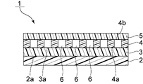
- FIG. 1 is a schematic cross-sectional view showing a tape laminate according to a first embodiment of the invention.
- FIG. 2 is a schematic plan view showing the second adhesive layer of the tape laminate according to the first embodiment of the invention.
- FIG. 3 is a schematic cross-sectional view showing a tape laminate according to a second embodiment of the invention.
- FIG. 4 is a schematic cross-sectional view showing a tape laminate according to a third embodiment of the invention.
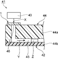
- FIG. 5 is a schematic cross-sectional view showing a microfluidic chip and a microfluidic device according to one embodiment of the present invention.
- FIG. 1 is a schematic cross-sectional view showing a tape laminate according to a first embodiment of the invention.
- the tape laminate 1 includes a substrate 2, a first adhesive layer 3, and a second adhesive layer 4.
- a first pressure-sensitive adhesive layer 3 is provided on the principal surface 2 a of the substrate 2 .
- a second adhesive layer 4 is provided on the main surface 3 a of the first adhesive layer 3 .
- the second adhesive layer 4 has a first major surface 4a and a second major surface 4b facing each other.
- the first main surface 4a of the second adhesive layer 4 is arranged on the first adhesive layer 3 side.
- a release film 5 is provided on the second main surface 4 b of the second pressure-sensitive adhesive layer 4 .
- the first adhesive layer 3 contains a gas generating agent that generates gas by applying light or heat.
- the second adhesive layer 4 has a plurality of through holes 6 .
- the through hole 6 is provided so as to extend from the first main surface 4a of the second adhesive layer 4 to the second main surface 4b.
- the planar shape of the through hole 6 is circular.
- the planar shape of the through-hole 6 is not particularly limited, and may be a substantially circular shape or a substantially rectangular shape including a rectangular shape.
- the diameter of the through-hole 6 can be, for example, 1 mm or more and 10 mm or less.
- the number of through-holes 6 in the second pressure-sensitive adhesive layer 4 may be plural as in the present embodiment, or may be one.
- the number of through-holes 6 in the second pressure-sensitive adhesive layer 4 can be, for example, 1 or more and 25 or less.
- the ratio of the area of the entire through-hole 6 to the area of the second adhesive layer 4 excluding the through-hole 6 can be, for example, 0.005 or more and 2 or less.
- the area of the entire through hole 6 can be, for example, 30 mm 2 or more and 8000 mm 2 or less in plan view.
- the area of the second pressure-sensitive adhesive layer 4 excluding the through-holes 6 can be, for example, 100 mm 2 or more and 7000 mm 2 or less in plan view.
- the area of the tape laminate 1 can be, for example, 130 mm 2 or more and 15000 mm 2 or less in plan view. Also, the thickness of the entire tape laminate 1 can be set to, for example, 0.01 mm or more and 1 mm or less.
- the tape laminate 1 of this embodiment is used with the release film 5 peeled off.
- the tape laminate 1 can be attached to an adherend from the second main surface 4b side of the second pressure-sensitive adhesive layer 4 .
- tape laminate 1 of the present embodiment has the above configuration, when it is used for channel sealing, peeling due to gas generation is unlikely to occur, and gas leakage and contamination can be suppressed.
- the second adhesive layer 4 having the through holes 6 is laminated on the main surface 3a of the first adhesive layer 3 containing the gas generating agent. Therefore, the gas generated from the first pressure-sensitive adhesive layer 3 can be sent to the channel through the through-holes 6 .
- the second main surface 4b of the second pressure-sensitive adhesive layer 4 is attached to the substrate on which the flow path is provided, it is possible to suppress peeling of the flow path sealing portion.
- the distance between the first adhesive layer 3 containing the gas generating agent and the channel can be made closer, so that the size of the device can be reduced when used in a microfluidic device or the like.
- the substrate is not particularly limited as long as it supports the pressure-sensitive adhesive layer, and examples thereof include resin films, fibers, and non-woven fabrics.
- resin films include films of polyester, polyolefin, and the like.
- the resin film is preferably a polyester film.
- polyester include polyethylene terephthalate and polybutylene phthalate, and polyethylene terephthalate is preferred.
- the thickness of the base material is not particularly limited, and can be, for example, 5 ⁇ m or more and 200 ⁇ m or less.
- the first adhesive layer contains an adhesive and a gas generating agent.
- the adhesive is not particularly limited, and for example, a (meth)acrylic adhesive, a rubber adhesive, a silicone adhesive, a urethane adhesive, an epoxy adhesive, or the like can be used. Among them, a silicone adhesive or a (meth)acrylic adhesive is preferable, and a (meth)acrylic adhesive is more preferable. These may be used individually by 1 type, and may use multiple types together. In addition, meth (acrylic) means methacrylic or acryl.
- the content of the adhesive in the first adhesive layer is not particularly limited, and is preferably 20% by mass or more, more preferably 40% by mass or more, preferably 95% by mass or less, more preferably 90% by mass or less. be. When the content of the adhesive in the first adhesive layer is within the above range, the adhesion to the second adhesive layer can be further enhanced.
- a gas generating agent is a compound that generates gas by applying a stimulus such as light or heat.
- a photoresponsive gas generating agent or a thermally responsive gas generating agent can be used, preferably a photoresponsive gas generating agent.
- the photoresponsive gas generating agent generates gas when exposed to light.
- Photoresponsive gas generating agents include, for example, azo compounds and azide compounds.
- azo compounds examples include 2,2′-azobis(N-cyclohexyl-2-methylpropionamide), 2,2′-azobis[N-(2-methylpropyl)-2-methylpropionamide], 2, 2'-azobis (N-butyl-2-methylpropionamide), 2,2'-azobis [N-(2-methylethyl)-2-methylpropionamide], 2,2'-azobis (N-hexyl- 2-methylpropionamide), 2,2'-azobis (N-propyl-2-methylpropionamide), 2,2'-azobis (N-ethyl-2-methylpropionamide), 2,2'-azobis ⁇ 2-methyl-N-[1,1-bis(hydroxymethyl)-2-hydroxyethyl]propionamide ⁇ , 2,2′-azobis ⁇ 2-methyl-N-[2-(1-hydroxybutyl)]propion amide ⁇ , 2,2′-azobis[2-methyl-N-(2-hydroxyethyl)propionamide], 2,2′-azobis[N-(2-propeny
- azide compounds examples include 3-azidomethyl-3-methyloxetane, terephthalazide, and polymers having an azide group.
- polymers having an azide group include glycidyl azide polymers.
- the glycidyl azide polymer can be obtained, for example, by ring-opening polymerization of p-tert-butylbenzazide and 3-azidomethyl-3-methyloxetane.
- These azide compounds may be used individually by 1 type, and may use multiple types together.
- the content of the gas generating agent in the first pressure-sensitive adhesive layer is not particularly limited, and is preferably 5% by mass or more, more preferably 10% by mass or more, preferably 75% by mass or less, and more preferably 55% by mass or less. is.
- the content of the gas generating agent is at least the above lower limit, the gas can be generated more efficiently by applying a stimulus such as light or heat.
- the content of the gas generating agent is equal to or less than the above upper limit, the adhesion to the second pressure-sensitive adhesive layer can be further enhanced.
- the first pressure-sensitive adhesive layer may further contain a photosensitizer, a cross-linking agent, and the like.
- the first pressure-sensitive adhesive layer contains an antioxidant such as a phenol, phosphorus, amine or sulfur antioxidant, or an ultraviolet absorber such as a benzotriazole or hydroxyphenyltriazine, as long as the effect of the present invention is not impaired.
- Halogenated flame retardants such as hexabromobiphenyl ether or decabromodiphenyl ether, flame retardants such as ammonium polyphosphate or trimethyl phosphate, calcium carbonate, talc, mica, clay, aerosil, silica, aluminum hydroxide, magnesium hydroxide, silica sand
- flame retardants such as ammonium polyphosphate or trimethyl phosphate, calcium carbonate, talc, mica, clay, aerosil, silica, aluminum hydroxide, magnesium hydroxide, silica sand
- Other additives such as inorganic fillers, antistatic agents, stabilizers, pigments, dyes, and binder resins may also be included.
- the thickness of the first pressure-sensitive adhesive layer is not particularly limited, it is preferably 5 ⁇ m or more, more preferably 20 ⁇ m or more, preferably 200 ⁇ m or less, and more preferably 100 ⁇ m or less. When the thickness of the first pressure-sensitive adhesive layer is within the above range, the adhesion to the second pressure-sensitive adhesive layer can be further enhanced.
- the method for forming the first pressure-sensitive adhesive layer is not particularly limited, and for example, it can be formed by a solution coating method.
- a solution coating method first, a first pressure-sensitive adhesive layer solution is prepared.
- the above-described adhesive and gas generating agent are mixed in a solvent. Thereby, a first adhesive layer solution can be prepared.
- each component is not particularly limited, and known methods can be used. For example, they can be mixed by stirring with a magnetic stirrer at 200 rpm for 1 hour.
- solvents examples include cyclohexane, hexane, methylcyclohexane, toluene, heptane, ethyl acetate, n-butyl acetate, isobutyl acetate, isopropyl acetate, methyl acetate, propyl acetate, tetrahydrofuran, acetone, pentane, methyl isobutyl ketone, methyl ethyl ketone, and the like. are mentioned.
- the solid content concentration in the first adhesive layer solution is preferably 20% to 80% by mass, more preferably 30% to 70% by mass.
- the first pressure-sensitive adhesive layer solution is evenly applied onto the substrate using a coater such as a knife coater, comma coater, or reverse coater, and dried. Thereby, the solvent can be removed to obtain the first adhesive layer.
- the first pressure-sensitive adhesive layer may be formed by transferring the layer formed on the release film onto the substrate.
- the second adhesive layer is composed of an adhesive.
- the adhesive is not particularly limited, and can be appropriately selected according to the type of adherend.
- a (meth)acrylic adhesive, a rubber adhesive, a silicone adhesive, a urethane adhesive, an epoxy adhesive, or the like can be used as the adhesive.
- a silicone pressure-sensitive adhesive or a (meth)acrylic pressure-sensitive adhesive is preferred, and a silicone pressure-sensitive adhesive is more preferred.
- These may be used individually by 1 type, and may use multiple types together.
- the adhesive that forms the second adhesive layer may be the same type of adhesive as the adhesive that forms the first adhesive layer, or may be of a different type.
- the pressure-sensitive adhesive that constitutes the second pressure-sensitive adhesive layer can be appropriately selected and used in consideration of the adhesiveness to the adherend.
- the pressure-sensitive adhesives constituting the first pressure-sensitive adhesive layer and the second pressure-sensitive adhesive layer should be the same type of pressure-sensitive adhesive layer. It is preferably composed of an agent.
- the second pressure-sensitive adhesive layer may contain a gas generating agent, but preferably does not substantially contain a gas generating agent. In this case, when used for channel sealing, separation due to gas generation can be made more difficult to occur. Note that "substantially free of gas generating agent" means that the content of the gas generating agent in the second pressure-sensitive adhesive layer is 1% by mass or less.
- the second pressure-sensitive adhesive layer may contain other additives similar to those of the first pressure-sensitive adhesive layer.
- the thickness of the second adhesive layer is not particularly limited, it is preferably 5 ⁇ m or more, more preferably 20 ⁇ m or more, preferably 200 ⁇ m or less, and more preferably 100 ⁇ m or less.
- the thickness of the second pressure-sensitive adhesive layer is within the above range, peeling due to gas generation can be made more difficult to occur when used for channel sealing.
- the second adhesive layer can be formed, for example, by a solution coating method in the same manner as the first adhesive layer.
- the method of forming the through-holes in the second pressure-sensitive adhesive layer is not particularly limited. At this time, it is desirable to form the second pressure-sensitive adhesive layer on the release film in advance, and form the through holes in a state in which the release films are adhered to both sides.
- the tape laminate can be obtained by transferring the second pressure-sensitive adhesive layer to the first pressure-sensitive adhesive layer after forming the through-holes.
- release film By providing the release film, the adhesive layer can be protected until the tape laminate is attached to the adherend. It is preferable that the release film can be easily peeled off. Note that the release film may not be provided.
- release film for example, a film coated with silicone or the like can be used.
- silicone for example, polyethylene terephthalate or polypropylene coated with silicone can be used.
- the thickness of the release film is not particularly limited, and can be, for example, 5 ⁇ m or more and 100 ⁇ m or less.
- FIG. 3 is a schematic cross-sectional view showing a tape laminate according to a second embodiment of the invention.
- a third adhesive layer 27 and a substrate 28 are provided between the first adhesive layer 3 and the second adhesive layer 4. .
- a third adhesive layer 27 is provided on the main surface 3 a of the first adhesive layer 3 .
- a substrate 28 is provided on the second main surface 27b of the third pressure-sensitive adhesive layer 27 .
- a second adhesive layer 4 is provided on the main surface 28 a of the base material 28 .
- the double-sided tape 29 is configured by providing the third adhesive layer 27 and the second adhesive layer 4 on both sides of the base material .
- the second adhesive layer 4 constitutes the non-supporting tape.
- the tape laminate 21 is provided with a through-hole 26 extending from the second main surface 4b of the second adhesive layer 4 to the first main surface 27a of the third adhesive layer 27. Details such as the shape and formation method of the through hole 26 are the same as those of the through hole 6 of the first embodiment. Also, the first main surface 27 a of the third adhesive layer 27 is in contact with the main surface 3 a of the first adhesive layer 3 . Also, the first main surface 27a and the second main surface 27b of the third adhesive layer 27 face each other.
- the base material 28 is not particularly limited as long as it supports the adhesive layer, and examples thereof include resin films, fibers, and nonwoven fabrics.
- resin films include films of polyester, polyolefin, and the like.
- the resin film is preferably a polyester film.
- polyester include polyethylene terephthalate and polybutylene phthalate, and polyethylene terephthalate is preferred.
- the thickness of the base material 28 is not particularly limited, and can be, for example, 5 ⁇ m or more and 100 ⁇ m or less.
- the adhesive constituting the third adhesive layer 27 is not particularly limited, and examples thereof include (meth)acrylic adhesive, rubber adhesive, silicone adhesive, urethane adhesive, and epoxy adhesive. can be used. Among them, a silicone pressure-sensitive adhesive or a (meth)acrylic pressure-sensitive adhesive is preferred, and a silicone pressure-sensitive adhesive is more preferred. These may be used individually by 1 type, and may use multiple types together.
- the third adhesive layer 27 may contain a gas generating agent, it preferably does not substantially contain a gas generating agent. In this case, when used for channel sealing, separation due to gas generation can be made more difficult to occur. In addition, the third adhesive layer 27 may contain other additives similar to those of the first adhesive layer 3 .
- the adhesive constituting the third adhesive layer 27 may be the same type of adhesive as the adhesive constituting the second adhesive layer 4, or may be of a different type. good. However, from the viewpoint of further improving productivity, it is preferable that the adhesives constituting the second adhesive layer 4 and the third adhesive layer 27 are made of the same kind of adhesive.
- the double-sided tape 29 having the through holes 26 is laminated on the main surface 3a of the first pressure-sensitive adhesive layer 3 containing the gas generating agent.
- a gas generated from the pressure-sensitive adhesive layer 3 can be fed into the flow path through the through-holes 26 .
- the second main surface 4b of the second pressure-sensitive adhesive layer 4 is attached to the substrate on which the flow path is provided, it is possible to suppress peeling of the flow path sealing portion.
- the distance between the first adhesive layer 3 containing the gas generating agent and the flow path can be made closer, so that when used in a microfluidic device or the like, the size of the device can be reduced.
- FIG. 4 is a schematic cross-sectional view showing a tape laminate according to the third embodiment of the invention.
- the tape laminate 31 is not provided with the third adhesive layer 27 .
- a single-sided tape 39 is configured by providing the second adhesive layer 4 on one side of the base material 28 .
- a through hole 36 is provided so as to penetrate the entire base material 28 from the second main surface 4b of the second adhesive layer 4. Details such as the shape and formation method of the through hole 36 are the same as those of the through hole 6 of the first embodiment.
- the single-sided tape 39 having the through holes 36 is laminated on the main surface 3a of the first pressure-sensitive adhesive layer 3 containing the gas generating agent.
- a gas generated from the pressure-sensitive adhesive layer 3 can be fed into the flow path through the through holes 36 .
- the second main surface 4b of the second pressure-sensitive adhesive layer 4 is attached to the substrate on which the flow path is provided, it is possible to suppress peeling of the flow path sealing portion.
- the distance between the first adhesive layer 3 containing the gas generating agent and the flow path can be made closer, so that when used in a microfluidic device or the like, the size of the device can be reduced.
- FIG. 5 is a schematic cross-sectional view showing a microfluidic chip and a microfluidic device according to one embodiment of the present invention.
- the microfluidic device 41 includes a microchannel chip 42 and a light irradiation section 43.
- the microchannel chip 42 includes a substrate 44 and the tape laminate 1 of the present invention described above.
- a microchannel 45 is provided in the substrate 44 .
- a gas inlet 46 is provided at the upstream end of the microchannel 45 .
- the tape laminate 1 is attached to the substrate 44 so as to seal the gas inlet 46 .
- the tape laminate 1 is attached to the substrate 44 from the second main surface 4b side of the second pressure-sensitive adhesive layer 4 .
- the through holes 6 of the tape laminate 1 and the gas inlets 46 of the substrate 44 are arranged so as to overlap each other.
- the 1st adhesive layer 3 shall contain the photoresponsive gas generating agent.
- the light irradiation unit 43 is provided to irradiate the tape laminate 1 with light.
- the gas is generated from the tape laminate 1 by irradiating light in the direction indicated by the arrow X from the light irradiation unit 43 .
- the gas generated from the tape laminate 1 is sent in the direction indicated by the arrow Y inside the microchannel 45 .
- the liquid Z placed in the microchannel 45 can be sent downstream.
- a heat irradiation unit may be provided in place of the light irradiation unit 43, and gas may be generated from the tape laminate 1 by heating.
- the microfluidic device 41 and the microchannel chip 42 of this embodiment have the tape laminate 1 as described above.
- the second adhesive layer 4 having the through-holes 6 is laminated on the main surface 3a of the first adhesive layer 3 containing the gas generating agent.
- the gas generated from 3 can be sent to the microchannel 45 through the through hole 6 .
- the second main surface 4b of the second pressure-sensitive adhesive layer 4 is attached to the substrate 44, it is possible to suppress peeling of the channel sealing portion.
- the distance between the first adhesive layer 3 containing the gas generating agent and the channel such as the microchannel 45 can be made closer, so that the microfluidic device 41 and the microchannel chip 42 can be miniaturized. can be achieved.
- the substrate 44 has a substantially rectangular plate shape. However, the shape of the substrate 44 is not particularly limited.
- the substrate 44 is composed of a substrate body 44a and a cover member 44b provided on the substrate body 44a.
- the substrate body 44a is made of injection molded synthetic resin.
- the cover member 44b is made of elastomer, synthetic resin, tape, or the like.
- the substrate body 44a and the cover member 44b may be made of other materials.
- the substrate main body 44a may be configured by laminating a plurality of synthetic resin sheets, and the structure and material thereof are not particularly limited.
- microchannel 45 refers to a fine channel that produces a micro effect when the fluid is transported.
- the fluid is strongly affected by surface tension and behaves differently from the fluid flowing through a normal large-sized channel.
- the cross-sectional shape and size of the microchannel 45 are not particularly limited as long as the channel produces the above micro effect.
- the dimension of the smaller side is preferably 20 ⁇ m or more, more preferably 50 ⁇ m or more, even more preferably 100 ⁇ m or more. From the viewpoint of further miniaturizing the microfluidic device 41, the dimension of the smaller side is preferably 5 mm or less, more preferably 1 mm or less, and even more preferably 500 ⁇ m or less.
- the diameter (minor axis in the case of an ellipse) is preferably 20 ⁇ m or more, more preferably 50 ⁇ m or more, and even more preferably 100 ⁇ m or more. From the viewpoint of further miniaturizing the microfluidic device 41, the diameter (minor axis in the case of an ellipse) is preferably 5 mm or less, more preferably 1 mm or less, and even more preferably 500 ⁇ m or less.
- the smaller side is preferably 5 ⁇ m or more, more preferably 10 ⁇ m or more, and even more preferably 20 ⁇ m or more. Also, the dimension of the smaller side is preferably 200 ⁇ m or less, more preferably 100 ⁇ m or less.
- the microfluidic device 41 and the microchannel chip 42 can be used for various tests by controlling liquid transfer and reaction of various specimens or samples.
- the gas generated from the tape laminate 1 can merge and mix a sample containing nucleic acids and a reaction reagent such as a PCR reaction reagent.
- the gas can be used to feed the mixed liquid to the detection channel for inspection.
- a liquid Z such as an extraction solution, a washing solution, a recovery solution, etc. used for purifying a test substance such as nucleic acid is previously held in the middle of the microchannel 45, and the gas generated from the tape laminate 1 is used to hold the liquid Z.
- the liquid Z that has been allowed to flow may be sent.
- the microfluidic device 41 and the microchannel chip 42 can also be used for cell culture.
- a liquid medium reservoir and a cell adhesion part are provided in the microchannel chip 42 .
- the liquid medium is sent from the liquid medium storage section to the cell adhesion section by the gas generated from the tape laminate 1 .
- cell culture can be performed within the microchannel chip 42 .
Landscapes
- Chemical & Material Sciences (AREA)
- Health & Medical Sciences (AREA)
- Chemical Kinetics & Catalysis (AREA)
- Clinical Laboratory Science (AREA)
- General Health & Medical Sciences (AREA)
- Hematology (AREA)
- Analytical Chemistry (AREA)
- Dispersion Chemistry (AREA)
- Organic Chemistry (AREA)
- Engineering & Computer Science (AREA)
- Combustion & Propulsion (AREA)
- Micromachines (AREA)
- Physical Or Chemical Processes And Apparatus (AREA)
Priority Applications (4)
| Application Number | Priority Date | Filing Date | Title |
|---|---|---|---|
| US18/576,207 US20240207848A1 (en) | 2021-07-12 | 2022-07-07 | Tape laminate, microfluidic chip and microfluidic device |
| CN202280048891.0A CN117616094A (zh) | 2021-07-12 | 2022-07-07 | 胶带叠层体、微流路芯片和微流体装置 |
| EP22842025.3A EP4372063A4 (en) | 2021-07-12 | 2022-07-07 | TAPE LAMINATE, MICROFLUIDIC CHIP AND MICROFLUIDIC DEVICE |
| JP2023534751A JP7750960B2 (ja) | 2021-07-12 | 2022-07-07 | テープ積層体、マイクロ流路チップ、及びマイクロ流体デバイス |
Applications Claiming Priority (2)
| Application Number | Priority Date | Filing Date | Title |
|---|---|---|---|
| JP2021-115189 | 2021-07-12 | ||
| JP2021115189 | 2021-07-12 |
Publications (1)
| Publication Number | Publication Date |
|---|---|
| WO2023286681A1 true WO2023286681A1 (ja) | 2023-01-19 |
Family
ID=84920260
Family Applications (1)
| Application Number | Title | Priority Date | Filing Date |
|---|---|---|---|
| PCT/JP2022/026903 Ceased WO2023286681A1 (ja) | 2021-07-12 | 2022-07-07 | テープ積層体、マイクロ流路チップ、及びマイクロ流体デバイス |
Country Status (5)
| Country | Link |
|---|---|
| US (1) | US20240207848A1 (https=) |
| EP (1) | EP4372063A4 (https=) |
| JP (1) | JP7750960B2 (https=) |
| CN (1) | CN117616094A (https=) |
| WO (1) | WO2023286681A1 (https=) |
Families Citing this family (1)
| Publication number | Priority date | Publication date | Assignee | Title |
|---|---|---|---|---|
| EP4220185A4 (en) * | 2020-09-28 | 2024-10-23 | Sekisui Chemical Co., Ltd. | Inspection chip |
Citations (6)
| Publication number | Priority date | Publication date | Assignee | Title |
|---|---|---|---|---|
| WO2009113567A1 (ja) * | 2008-03-11 | 2009-09-17 | 積水化学工業株式会社 | マイクロ流体デバイス |
| JP2010202833A (ja) * | 2009-03-05 | 2010-09-16 | Sekisui Chem Co Ltd | 電子部品加工用粘着テープ |
| JP2011021094A (ja) * | 2009-07-15 | 2011-02-03 | Lintec Corp | 粘着シート及びその製造方法 |
| JP2019070104A (ja) * | 2017-10-06 | 2019-05-09 | 積水化学工業株式会社 | 表面保護フィルム |
| JP2019108231A (ja) | 2017-12-15 | 2019-07-04 | 積水化学工業株式会社 | ガス発生材、ガス発生材の製造方法及びマイクロポンプ |
| WO2021125153A1 (ja) * | 2019-12-19 | 2021-06-24 | 昭和電工株式会社 | 粘着シート |
Family Cites Families (5)
| Publication number | Priority date | Publication date | Assignee | Title |
|---|---|---|---|---|
| JP4540962B2 (ja) * | 2003-10-10 | 2010-09-08 | リンテック株式会社 | 粘着シートおよびその製造方法 |
| JP4704828B2 (ja) * | 2004-09-29 | 2011-06-22 | 積水化学工業株式会社 | ウエハ貼着用粘着シート及びダイ接着用接着剤層付きicチップの製造方法 |
| US20090092819A1 (en) * | 2007-10-09 | 2009-04-09 | Adhesives Research, Inc. | Porous pressure sensitive adhesive and tapes |
| EP2328056B1 (en) * | 2009-11-26 | 2014-09-10 | Dialog Semiconductor GmbH | Low-dropout linear regulator (LDO), method for providing an LDO and method for operating an LDO |
| JP2012072007A (ja) * | 2010-09-28 | 2012-04-12 | Sekisui Chem Co Ltd | ガス発生剤及びマイクロポンプ |
-
2022
- 2022-07-07 EP EP22842025.3A patent/EP4372063A4/en active Pending
- 2022-07-07 CN CN202280048891.0A patent/CN117616094A/zh active Pending
- 2022-07-07 WO PCT/JP2022/026903 patent/WO2023286681A1/ja not_active Ceased
- 2022-07-07 US US18/576,207 patent/US20240207848A1/en active Pending
- 2022-07-07 JP JP2023534751A patent/JP7750960B2/ja active Active
Patent Citations (6)
| Publication number | Priority date | Publication date | Assignee | Title |
|---|---|---|---|---|
| WO2009113567A1 (ja) * | 2008-03-11 | 2009-09-17 | 積水化学工業株式会社 | マイクロ流体デバイス |
| JP2010202833A (ja) * | 2009-03-05 | 2010-09-16 | Sekisui Chem Co Ltd | 電子部品加工用粘着テープ |
| JP2011021094A (ja) * | 2009-07-15 | 2011-02-03 | Lintec Corp | 粘着シート及びその製造方法 |
| JP2019070104A (ja) * | 2017-10-06 | 2019-05-09 | 積水化学工業株式会社 | 表面保護フィルム |
| JP2019108231A (ja) | 2017-12-15 | 2019-07-04 | 積水化学工業株式会社 | ガス発生材、ガス発生材の製造方法及びマイクロポンプ |
| WO2021125153A1 (ja) * | 2019-12-19 | 2021-06-24 | 昭和電工株式会社 | 粘着シート |
Non-Patent Citations (1)
| Title |
|---|
| See also references of EP4372063A4 |
Also Published As
| Publication number | Publication date |
|---|---|
| JP7750960B2 (ja) | 2025-10-07 |
| EP4372063A1 (en) | 2024-05-22 |
| US20240207848A1 (en) | 2024-06-27 |
| JPWO2023286681A1 (https=) | 2023-01-19 |
| EP4372063A4 (en) | 2025-07-23 |
| CN117616094A (zh) | 2024-02-27 |
Similar Documents
| Publication | Publication Date | Title |
|---|---|---|
| KR101560424B1 (ko) | 마이크로유체 디바이스 | |
| JP5700466B2 (ja) | 再剥離粘着剤組成物、粘着シート及びテープ | |
| CN104130723A (zh) | 热剥离型粘合带和电子部件的切断方法 | |
| US20100189601A1 (en) | Capillary | |
| JP2006509063A (ja) | ポリ(メト)アクリレ−トに基づく感圧接着剤 | |
| JP7750960B2 (ja) | テープ積層体、マイクロ流路チップ、及びマイクロ流体デバイス | |
| EP2227690A1 (en) | The micro-chamber plate, manufacturing method thereof | |
| KR20170094320A (ko) | 양면 점착 테이프 및 그 제조 방법 | |
| CA2387064A1 (en) | Sealing for microfluidic devices | |
| JP2018059916A (ja) | マイクロ流路チップ | |
| JP2022179049A (ja) | マイクロ流路チップ、マイクロ流体デバイス、送液システム、及び送液方法 | |
| JP5291415B2 (ja) | マイクロ流体送液装置 | |
| US10987935B1 (en) | Organic solvent sealing tape | |
| JP2013099286A (ja) | 細胞培養容器 | |
| JP6446146B2 (ja) | マイクロチップ | |
| JP2020041058A (ja) | 両面粘着シートおよび剥離シート付き両面粘着シート | |
| JPH07157735A (ja) | 再剥離型粘着剤組成物 | |
| JP5919776B2 (ja) | 細胞培養容器の製造方法 | |
| CN111278941A (zh) | 胶带的等离子体边缘封装 | |
| JP5802894B2 (ja) | マイクロ流体チップ | |
| US20250121601A1 (en) | Silcone tape having improved adhesive properties | |
| JP2008076208A (ja) | プラスチック製マイクロチップ、及びそれを利用したバイオチップ又はマイクロ分析チップ。 | |
| JP2019211266A (ja) | 検査用具及び試薬の混合方法 | |
| TW202340307A (zh) | 熱硬化性樹脂組成物、顯示裝置用密封劑及顯示裝置 | |
| JP2019110779A (ja) | マイクロチップ |
Legal Events
| Date | Code | Title | Description |
|---|---|---|---|
| 121 | Ep: the epo has been informed by wipo that ep was designated in this application |
Ref document number: 22842025 Country of ref document: EP Kind code of ref document: A1 |
|
| ENP | Entry into the national phase |
Ref document number: 2023534751 Country of ref document: JP Kind code of ref document: A |
|
| WWE | Wipo information: entry into national phase |
Ref document number: 18576207 Country of ref document: US |
|
| WWE | Wipo information: entry into national phase |
Ref document number: 202280048891.0 Country of ref document: CN |
|
| WWE | Wipo information: entry into national phase |
Ref document number: 2022842025 Country of ref document: EP |
|
| NENP | Non-entry into the national phase |
Ref country code: DE |
|
| ENP | Entry into the national phase |
Ref document number: 2022842025 Country of ref document: EP Effective date: 20240212 |