WO2023286458A1 - 電子機器制御装置、通信端末および電子機器 - Google Patents
電子機器制御装置、通信端末および電子機器 Download PDFInfo
- Publication number
- WO2023286458A1 WO2023286458A1 PCT/JP2022/021336 JP2022021336W WO2023286458A1 WO 2023286458 A1 WO2023286458 A1 WO 2023286458A1 JP 2022021336 W JP2022021336 W JP 2022021336W WO 2023286458 A1 WO2023286458 A1 WO 2023286458A1
- Authority
- WO
- WIPO (PCT)
- Prior art keywords
- user
- electronic device
- unit
- signal
- activation
- Prior art date
- Legal status (The legal status is an assumption and is not a legal conclusion. Google has not performed a legal analysis and makes no representation as to the accuracy of the status listed.)
- Ceased
Links
Images









Classifications
-
- H—ELECTRICITY
- H04—ELECTRIC COMMUNICATION TECHNIQUE
- H04L—TRANSMISSION OF DIGITAL INFORMATION, e.g. TELEGRAPHIC COMMUNICATION
- H04L12/00—Data switching networks
- H04L12/28—Data switching networks characterised by path configuration, e.g. LAN [Local Area Networks] or WAN [Wide Area Networks]
- H04L12/2803—Home automation networks
- H04L12/2807—Exchanging configuration information on appliance services in a home automation network
-
- H—ELECTRICITY
- H04—ELECTRIC COMMUNICATION TECHNIQUE
- H04L—TRANSMISSION OF DIGITAL INFORMATION, e.g. TELEGRAPHIC COMMUNICATION
- H04L12/00—Data switching networks
- H04L12/28—Data switching networks characterised by path configuration, e.g. LAN [Local Area Networks] or WAN [Wide Area Networks]
- H04L12/2803—Home automation networks
- H04L12/2816—Controlling appliance services of a home automation network by calling their functionalities
- H04L12/282—Controlling appliance services of a home automation network by calling their functionalities based on user interaction within the home
-
- H—ELECTRICITY
- H04—ELECTRIC COMMUNICATION TECHNIQUE
- H04Q—SELECTING
- H04Q9/00—Arrangements in telecontrol or telemetry systems for selectively calling a substation from a main station, in which substation desired apparatus is selected for applying a control signal thereto or for obtaining measured values therefrom
Definitions
- the present invention relates to technology for controlling one or more electronic devices.
- remote controls Many home appliances come with remote controllers (hereinafter abbreviated as "remote controls”). As the number of home electric appliances increases, the number of remote controllers also increases, making the management of remote controllers complicated. It would be convenient if a plurality of home electric appliances could be collectively controlled by a single remote control (see Patent Documents 1 and 2).
- Patent Document 1 discloses a technique for integrating the functions of multiple remote controllers into one device. However, Patent Document 1 does not assume that a plurality of peripheral devices (household appliances) are controlled simultaneously by a single operation.
- the controller disclosed in Patent Document 2 can simultaneously control multiple devices with a single operation. For example, when the voice command "Good morning” is input, the air conditioning equipment, lighting equipment, and electric shutters in the living room can be driven all at once. Furthermore, this controller uses additional information such as "period” to change the device control method. For example, the air conditioner is set to "cooling” in summer, and is set to "heating” in winter (see paragraph [0081] of Patent Document 2). However, in the case of the controller of Patent Document 2, it is necessary to associate the command with the device to be controlled in advance, and to properly set the control method of the device according to the additional information in advance. is considered to be complicated.
- the present invention has been completed based on the recognition of the above problems, and its main purpose is to propose a technique for appropriately controlling electronic devices such as home electric appliances according to the user's lifestyle. .
- An electronic device control device includes a basic setting storage unit that stores basic setting information that associates one or more operating conditions of an electronic device with a user ID and a time period, and specifies a user. and a device control unit that controls one or more electronic devices by referring to basic setting information based on the specified user and the current time.
- the device control unit changes the operating conditions for the specified electronic device and updates the basic setting information.
- An electronic device includes a receiving unit that receives a control signal including a command ID, a device ID, and an operation command from an external electronic device control device by short-range wireless communication; , an operation control unit that sets the operation of the device according to an operation command included in the control signal, and a transmission unit that transmits the control signal by short-range wireless communication.
- the signal transmission unit refers to the instruction ID of the received control signal and transmits the control signal on condition that the control signal has not been received.
- An electronic device control device includes a usage history management unit that manages the usage history of an electronic device for each user, a start reception unit that receives a start signal for the electronic device together with a user ID from a user terminal, An activation transmission unit that transmits the activation signal to the electronic device when the activation signal is received, and a setting transmission unit that transmits the setting signal based on the usage history corresponding to the user ID to the electronic device.
- a communication terminal includes an operation screen display unit that displays an operation screen including activation buttons corresponding to each of a plurality of electronic devices, a confirmation signal reception unit that receives a confirmation signal from an electronic device control device, After receiving the confirmation signal, a specified information transmitting unit that transmits the specified information of the electronic device to the electronic device control device, an operation screen generation unit that adds the start button of the electronic device to the operation screen after transmitting the specified information, and an operation screen an activation signal transmission unit configured to transmit an activation signal for an electronic device corresponding to the selected activation button to the electronic device control device when one of the plurality of activation buttons displayed in the display is selected.
- An electronic device includes a usage history management unit that manages the usage history of the device for each user, an activation reception unit that receives an activation signal together with a user ID from a user terminal, and a , an activation control unit that activates the device itself; and a setting unit that initially sets operating conditions of the device based on the usage history corresponding to the user ID.
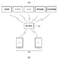
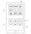
- FIG. 1 is a system configuration diagram of an electronic equipment integration system; FIG. It is a screen figure of the operation screen of a user terminal.
- 3 is a functional block diagram of an integrated terminal in the first embodiment;
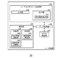
- FIG. 3 is a functional block diagram of a user terminal;
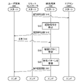
- FIG. 10 is a sequence diagram showing the process of newly registering an air conditioner in the device list;
- FIG. 10 is a sequence diagram showing a process when the air conditioner is started;
- FIG. 9 is a functional block diagram of an integrated terminal in the second embodiment;
- 4 is a data structure diagram of utterance setting information;
- FIG. Fig. 10 is a flow chart showing the process when a speech command is detected; It is a data structure diagram of life information.
- 4 is a data structure diagram of basic setting information;
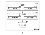
- FIG. 3 is a functional block diagram of electronic equipment involved in control by an integrated terminal;
- FIG. 10 is a sequence diagram showing a method of transferring control commands by a relay method;
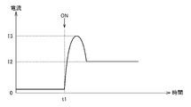
- FIG. 4 is a schematic diagram for explaining an inrush current;
- FIG. 4 is a schematic diagram showing changes in current when the electronic device is turned off;
- 4 is a flow chart showing the process of the integrated terminal when the electronic device is turned on;
- the electronic device integration system will be described below based on the first embodiment and the second embodiment.
- the first embodiment will be described on the assumption that a plurality of electronic devices are controlled by remote controllers.
- the integrated terminal (electronic device control device) in the first embodiment sets the operating conditions of the electronic device based on the usage history of the electronic device.
- a description will be given on the assumption that the integrated terminal preemptively controls a plurality of electronic devices according to the lifestyle of the user.
- the user can also convey his/her intention to the integrated terminal by voice or the like.
- the present embodiment when the first embodiment and the second embodiment are collectively referred to, or when they are not distinguished from each other, they will be referred to as "the present embodiment".
- FIG. 1 is a system configuration diagram of an electronic device integration system 200.
- the electronic device integration system 200 includes an integrated terminal 100 , multiple user terminals 300 , and multiple electronic devices 400 .
- a user terminal 300 is a communication terminal owned by a user, and is assumed to be a laptop PC, a tablet PC, a smart phone, or the like. It is assumed that the user terminal 300 in this embodiment is a smart phone.
- a user is identified by a "user ID".
- the electronic device 400 is a device (electronic device) that can be electronically controlled, such as an automobile, an air conditioner (hereinafter referred to as "air conditioner"), a television, a lighting device, and a multi-storey parking lot.
- air conditioner air conditioner
- the user can collectively control a plurality of electronic devices 400 using the user terminal 300 and the integrated terminal 100 .
- the integrated terminal 100 (electronic device control device) is a relay device that receives a control signal from the user terminal 300 and comprehensively controls one or more electronic devices 400 according to this control signal.
- the integrated terminal 100 is installed in a house and collectively receives control signals from a plurality of user terminals 300 of a plurality of users.
- the control signal here means a signal for remotely controlling the electronic device 400 such as activation, setting, and termination.
- Dedicated software (hereinafter referred to as "remote control software") is installed in the user terminal 300 in advance.
- the remote control software displays a plurality of buttons (operation interface) on the screen of the user terminal 300 (described later). For example, when the user touches the "go home” button displayed on user terminal 300, user terminal 300 transmits a predetermined control signal corresponding to "go home” to integrated terminal 100 together with the user ID.
- Integrated terminal 100 activates, for example, the entrance lighting device, the living room lighting device, and the living room television all at once in response to this “go home” control signal.
- the user can activate multiple electronic devices such as the entrance lighting, the living room lighting, and the television all at once.
- the remote control software has a voice recognition function. Therefore, when the user utters, for example, "go home", a similar control signal is transmitted to integrated terminal 100 together with the user ID.
- integrated terminal 100 may detect the uttered voice instead of user terminal 300 and identify the user based on the voice pattern of the uttered voice.
- the remote control software may display the "Video” button.
- the integrated terminal 100 may activate the television and video (Blu-ray recorder) and set the input switching of the television to "video".
- the user wants to watch a video he/she can start watching the video simply by touching the "video" button on the integrated terminal 100 with one touch.
- the remote control software may display the "car” button.
- the integrated terminal 100 sends a control signal (engine start instruction) to the car, and the car engine starts.
- the integrated terminal 100 also transmits a control signal (a gate opening instruction) to the electric shutter of the parking lot, thereby opening the electric shutter.
- a control signal a gate opening instruction
- the integrated terminal 100 may start the engine of the car, and when the engine of the car is started, the electric shutter may be opened.
- the automobile may send a gate-opening signal to the electric shutter when the engine is started, and the electric shutter may start the gate-opening operation when receiving the gate-opening signal.
- the electric shutter may have a voice recognition function and start opening the gate when it detects the engine start sound of the automobile.
- FIG. 2 is a screen diagram of an operation screen of the user terminal 300.
- the remote control software causes an operation screen 310 including a plurality of activation buttons 306 to be displayed.
- Operation screen 310 includes device operation area 302 and scene operation area 304 .
- Device operation area 302 includes activation button 306 corresponding to the electronic device.
- the scene manipulation area 304 includes activation buttons 306 corresponding to scenes.
- a scene is a concept that expresses a user's situation, such as "coming home” described above.
- the start button may display words uttered by the user in the scene, such as "Good morning”, “Itadakimasu”, “I'm going", “I'm home", and “Good night”. It may be an icon.
- the activation signal corresponding to the activation button 306 is transmitted from the user terminal 300 to the integrated terminal 100 .
- an activation signal corresponding to activation button 306 is transmitted to integrated terminal 100 .
- the activation button 306 or a predetermined voice corresponding to the activation button 306 serves as a trigger for activating various electronic devices 400 .
- a user interface that generates an activation signal is hereinafter referred to as a "activation interface".
- the activation interface may be a touch button, such as activation button 306, or a voice recognition type interface.
- the user can activate a plurality of electronic devices 400 on one user terminal 300 by touching the activation button 306 .
- the integrated terminal 100 provides the user terminal 300 with the operation screen 310 in the form of a web page.
- the operation screen 310 may include not only the activation button 306 but also various setting buttons (not shown). For example, when the air conditioner activation button 306 is touched, various setting buttons for setting the temperature, air volume, etc. of the air conditioner may be displayed. Also, the activation button 306 may be a button for performing various settings.
- FIG. 3 is a functional block diagram of the integrated terminal 100 according to the first embodiment.
- Each component of the integrated terminal 100 includes computing units such as a CPU (Central Processing Unit) and various co-processors, storage devices such as memory and storage, and hardware including wired or wireless communication lines connecting them. , and is implemented by software that is stored in a storage device and supplies processing instructions to the calculator.
- a computer program may consist of a device driver, an operating system, various application programs located in their higher layers, and a library that provides common functions to these programs.
- Each block described below represents a functional block rather than a hardware configuration. The same applies to the user terminal 300 shown in FIG. 4, the integrated terminal 100 in the second embodiment shown in FIG. 7, and the electronic device 400 shown in FIG.
- Integrated terminal 100 includes communication unit 102 , data processing unit 104 and data storage unit 106 .
- the communication unit 102 is in charge of communication processing with the user terminal 300 and the electronic device 400 via a wireless communication network.
- the data storage unit 106 stores various information.
- the data processing unit 104 executes various processes based on data acquired by the communication unit 102 and data stored in the data storage unit 106 .
- Data processing unit 104 also functions as an interface for communication unit 102 and data storage unit 106 .
- the communication unit 102 includes a transmission unit 108 that transmits various types of information to external devices (the user terminal 300 and the electronic device 400), and a reception unit 110 that receives various types of information from the external devices.
- Transmission section 108 includes activation transmission section 112 , setting transmission section 114 , confirmation signal transmission section 116 and operation provision section 118 .
- Activation transmission section 112 transmits a first activation signal for activating electronic device 400 .
- the setting transmission unit 114 transmits to the electronic device 400 a first setting signal for setting various operations of the electronic device 400 , such as the temperature of the air conditioner, the channel of the TV program, the brightness of the lighting in the living room, and the like.
- Confirmation signal transmission section 116 transmits a confirmation signal to user terminal 300 (described later).
- the operation providing unit 118 transmits a web page showing the operation screen 310 to the user terminal 300 .
- Receiver 110 includes activation receiver 120 , setting receiver 122 , signal detector 124 , designation information receiver 126 and name receiver 128 .
- Activation receiving section 120 receives a second activation signal for activating electronic device 400 from user terminal 300 .
- the electronic device 400 cannot be activated by the second activation signal transmitted from the user terminal 300 to the integrated terminal 100 .
- the activation transmission unit 112 converts the second activation signal into a first activation signal corresponding to the electronic device 400 and transmits the first activation signal to the electronic device 400 .
- start signal When the first start signal and the second start signal are collectively referred to or when they are not distinguished from each other, they are simply referred to as "start signal”.
- the setting reception unit 122 receives a second setting signal for setting the operation of the electronic device 400 from the user terminal 300 .
- the second setting signal transmitted from the user terminal 300 to the integrated terminal 100 cannot be used to change the setting of the electronic device 400 .
- setting transmission section 114 converts the second setting signal into a first setting signal and then transmits the first setting signal to electronic device 400 .
- the first setting signal and the second setting signal are collectively referred to or when they are not distinguished from each other, they are simply referred to as "setting signal”.
- the activation signal and the setting signal are collectively referred to as a "control signal”.
- the signal detection unit 124 detects a control signal transmitted from the dedicated remote controller of the electronic device 400 .
- the designation information receiving unit 126 receives designation information for identifying the electronic device 400 from the user terminal 300 (described later).
- the name receiving unit 128 receives from the user terminal 300 a specification of the operation name of the activation interface in the scene operation area 304 .
- Data storage unit 106 includes usage history storage unit 140 , signal pattern storage unit 142 and device list storage unit 144 .
- the usage history storage unit 140 manages the usage history of the electronic device 400 for each user. For example, according to user P1's air conditioner usage history, there is a 60% or more possibility that the heater will be turned on during the time period from 18:00 to 19:00 in January, and the set temperature of the heater will be set to 25 degrees. Information such as 55% is registered.
- the signal pattern storage unit 142 stores signal patterns of control signals for the electronic device 400 (eg, first activation signal, first setting signal).
- the "signal pattern" referred to here may be the waveform and frequency of the control signal (digital signal). For example, the waveform of the digital signal included in the activation signal of the air conditioner X is registered. When the signal detection unit 124 intercepts an unknown control signal, if the waveform of this control signal matches the waveform of the start signal of the air conditioner X, it determines that this control signal is the start signal of the air conditioner X (known). do.
- the device list storage unit 144 manages a list of electronic devices 400 to be controlled as a device list. In this embodiment, the device list storage unit 144 manages the device list for each user.
- Data processing unit 104 includes usage history management unit 130 , setting determination unit 132 , electronic device registration unit 134 , name registration unit 136 and operation screen generation unit 138 .
- Usage history management unit 130 manages usage history for each combination of a user and electronic device 400 .
- the setting determination unit 132 determines setting values for the electronic device 400 based on the usage history.
- the electronic device registration unit 134 registers the electronic device 400 in the device list.
- Operation screen generator 138 generates a web page for operation screen 310 .
- FIG. 4 is a functional block diagram of the user terminal 300. As shown in FIG. As described above, in the first embodiment, it is assumed that the functions shown in FIG. 4 are exhibited by installing the remote control software in a general smart phone.
- the user terminal 300 includes a user interface processing section 322 , a communication section 324 , a data processing section 326 and a data storage section 328 .
- the user interface processing unit 322 is in charge of processing related to the user interface, such as image display and audio output, in addition to receiving operations from the user.
- the communication unit 324 is in charge of communication processing with the integrated terminal 100 via a wireless communication network.
- the data storage unit 328 stores various data.
- the data processing unit 326 executes various processes based on data acquired by the user interface processing unit 322 and the communication unit 324 and data stored in the data storage unit 328 .
- the data processing unit 326 also functions as an interface for the user interface processing unit 322 , the communication unit 324 and the data storage unit 328 .
- the user interface processing section 322 includes an input section 330 and an output section 332 .
- the input unit 330 receives various operations from the user.
- the input unit 330 can also receive voice input from the user.
- the output unit 332 outputs various information such as images and sounds.
- Output unit 332 includes an operation screen display unit 334 .
- the operation screen display section 334 displays the input section 330 .
- the communication unit 324 includes a transmission unit 336 that transmits various information to the integrated terminal 100 and a reception unit 338 that receives various information from an external device.
- Transmitter 336 includes designation information transmitter 340 and activation signal transmitter 342 .
- Designated information transmitting section 340 transmits designated information indicating the name of electronic device 400 .
- the activation signal transmission unit 342 transmits the second activation signal to the integrated terminal 100 .
- the second activation signal includes the user ID and the device ID of electronic device 400 to be operated.
- Receiver 338 includes an acknowledgment signal receiver 344 .
- the confirmation signal receiving section 344 receives the confirmation signal from the integrated terminal 100 .
- FIG. 5 is a sequence diagram showing the process of newly registering an air conditioner in the device list.
- a description will be given on the assumption that when an air conditioner (electronic device 400) is newly purchased, the integrated terminal 100 recognizes the air conditioner. The same applies when the integrated terminal 100 is newly introduced.
- the user operates a remote controller attached to the air conditioner to transmit a first activation signal to the air conditioner (S10).
- the air conditioner is activated by the first activation signal.
- the signal detection unit 124 of the integrated terminal 100 intercepts the first activation signal (eg, infrared signal) (S12).
- the signal pattern storage unit 142 signal patterns of control signals (activation signals and setting signals) of various electronic devices 400, that is, information on signal frequencies and waveforms are registered in advance.
- the confirmation signal transmission unit 116 transmits a confirmation signal to the user terminal 300 (S14).
- the confirmation signal is broadcast to user terminals 300 within a predetermined range from the integrated terminal 100 .
- the user When the user receives the confirmation signal, the user responds to the confirmation signal by sending back the designation information that designates the name of the electronic device 400 "air conditioner” (S16).
- the specified information transmitting unit 340 transmits the specified information including the user ID and the name “air conditioner” to the integrated terminal 100 .
- the electronic device registration unit 134 sets the device ID to "air conditioner”, associates the user ID with the device ID of "air conditioner”, and registers them in the device list (S18). Further, the electronic device registration unit 134 registers the signal pattern of the first activation signal detected in S12 in the signal pattern storage unit 142 in association with the device ID of the air conditioner (S20).
- the operation screen generation unit 138 of the integrated terminal 100 newly generates an operation screen 310 including an "air conditioner" activation interface.
- the operation providing unit 118 transmits the generated web page of the operation screen 310 to the integrated terminal 100 (S22). At this time, the device ID is also notified from the integrated terminal 100 to the user terminal 300 .
- the integrated terminal 100 can register the newly purchased "air conditioner” as a new control target after obtaining confirmation from the user, triggered by interception of the first activation signal. Further, the user can also acquire the operation screen 310 (activation interface) for operating the air conditioner from the user terminal 300 by activating the air conditioner with the dedicated remote control.
- the electronic device registration unit 134 determines whether it matches any of the registered signal patterns. If not registered, the processing from S12 onwards is executed, and the signal pattern is learned at S20. The same applies to the first setting signal. Integrated terminal 100 confirms with the user if the signal pattern is new (unregistered) even when intercepting the second setting signal.
- the user When registering a new air conditioner, the user may be asked to confirm the registration. Specifically, at the same time as sending the confirmation signal in S14 or after receiving the designation information in S16, the sending unit 108 of the integrated terminal 100 sends a message to the user, "This is a new home appliance. Do you want to register it?" may be sent.
- the electronic device registration unit 134 may register the air conditioner in the device list on the condition that registration approval has been received from the user.
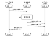
- FIG. 6 is a sequence diagram showing the process when the air conditioner is started. Assume that the user first selects the air conditioner as an activation target on the operation screen 310 of the user terminal 300 .
- the activation signal transmission unit 342 of the user terminal 300 transmits the second activation signal together with the user ID and the device ID to the integrated terminal 100 (S30).
- Activation receiver 120 of integrated terminal 100 receives the second activation signal.
- the setting determination unit 132 refers to the usage history of the user's air conditioner and determines the setting value of the air conditioner. For example, assume that the outside air temperature is 30° C. or higher during the time period from 18:00 to 19:00 when the second activation signal is transmitted. If “25 degrees” and “strong wind” were set most frequently under the same conditions in the past, the setting determination unit 132 determines that "25 degrees” and "strong wind” are appropriate as the setting values for the air conditioner. (S32).
- the activation transmission unit 112 transmits the first activation signal to the air conditioner (S34). Subsequently, the setting transmission unit 114 transmits a setting signal to the electronic device 400 with the setting values of "25 degrees" and "strong wind” (S36). The transmission unit 108 of the integrated terminal 100 transmits a text message indicating the setting contents to the user terminal 300 (S38). According to such a control method, the user terminal 300 can start the air conditioner with the optimum set value based on the past usage history, simply by instructing the air conditioner to start.
- the user can also change the setting value. For example, when the user says “it's a little hot” or touches the "lower temperature” button on the user terminal 300, the user terminal 300 transmits setting request information indicating a desire to lower the temperature to the integrated terminal 100. At this time, the setting determining unit 132 determines that "24 degrees", which is one degree lower than "25 degrees”, is “more appropriate”, and the setting transmitting unit 114 instructs to lower the set temperature of the air conditioner by one degree. Also, the usage history management unit 130 updates the usage history of this user's air conditioner based on the new settings.
- the setting determination unit 132 determines the average value of various temperatures set under the external condition that "the outside temperature is 30 degrees or higher in the time period from 18:00 to 19:00" as “based on the usage history.” Appropriate set temperature”. For example, in the case of the above example, when the user desires "24 degrees", the setting determination unit 132 uses "24.5 degrees”, which is the average value of "24 degrees” and "25 degrees”, from the next time onwards. It may be determined as an appropriate setting temperature based on the history. The same is true for wind power.
- the integrated terminal 100 may be in a constantly activated state, or may be activated by an activation signal from the user terminal 300.
- the operation providing unit 118 of the integrated terminal 100 transmits the operation screen 310 to the user terminal 300 that issued the activation instruction.
- the user terminal 300 is notified of the URL for displaying the operation screen 310 . By clicking this URL, the user can cause the web browser to display the operation screen 310 .
- a plurality of electronic devices 400 can be activated at the same time. For example, it is assumed that the user activates the television with the remote control of the television and then activates the air conditioner with the remote control of the air conditioner. The activation of the air conditioner and the television at this time may be performed by the user terminal 300 instead of the dedicated remote control. After that, the user inputs an arbitrary operation name. For example, suppose you enter the name "Relax". The specified information transmission unit 340 of the user terminal 300 transmits name information including the operation name “relax” to the integrated terminal 100 together with the user ID.
- the name reception unit 128 of the integrated terminal 100 receives the name information.
- the signal detection unit 124 detects that the television and the remote control have been activated within a predetermined period of time, for example, within 10 seconds before receiving the name information.
- the name registration unit 136 sets a command ID for the name "relax”, and associates "television” and "air conditioner” with this command ID.
- the operation screen generator 138 generates an operation screen 310 including a "relax" button for this user.
- the television and the remote control can be activated at the same time. More specifically, for example, assume that the user touches the "relax" button. At this time, a second activation signal (multi-activation signal) is transmitted from the user terminal 300 to the integrated terminal 100 together with a command ID corresponding to "relax".
- the setting determination unit 132 recognizes that the objects to be activated by this command ID are "TV" and "air conditioner”. The setting determination unit 132 sets an appropriate channel based on the television usage history. Similarly, the setting determination unit 132 sets the temperature of the air conditioner based on the use history of the air conditioner.
- the setting determination unit 132 selects the television program A when the television is activated. Assume that the user wants TV program B instead of TV program A. As a result, it is assumed that the probability that TV program A will be selected changes to 50% and the probability that TV program B will be selected changes to 50% in the same time slot. In this case, the setting determining unit 132 preferentially selects the recently selected television program B in the same time slot thereafter.
- the usage history is a combination of user, time period, external environment, device ID (electronic device 400), and operating conditions.
- the “external environment” is information indicating the state of the surrounding environment of the user, such as outside temperature, humidity, presence or absence of noise, and the like.
- the usage history management unit 130 recognizes the external environment from various sensors installed indoors and outdoors.
- the operating conditions indicate various set values for controlling the electronic device 400, such as set temperatures, timers, and channels.
- the usage history management unit 130 appropriately updates the usage history for each user based on the operation content of the electronic device 400 by the user.
- the setting determination unit 132 may set the temperature of the air conditioner to 26 degrees.
- the usage history management unit 130 updates the usage history. As the usage history is updated, the setting determination unit 132 may lower the set temperature of the air conditioner below 26 degrees under the same conditions from the next time. Thus, the usage history management unit 130 updates the usage history based on the user's operation, and the setting determination unit 132 controls the electronic device 400 based on the usage history.
- the hardware configuration of the electronic equipment integration system 200 in the second embodiment is the same as in the first embodiment (see FIG. 1).
- the user terminal 300 controls various electronic devices 400 via the integrated terminal 100 .
- the integrated terminal 100 grasps the lifestyle of the user and preemptively controls various electronic devices 400 before the user gives an instruction.
- the user can also intervene in various settings prepared by the integrated terminal 100 by voice or by the user terminal 300 .
- the explanation will be centered on voice intervention.
- FIG. 7 is a functional block diagram of the integrated terminal 100 according to the second embodiment.
- FIG. 7 illustrates the functional blocks necessary for realizing the control in the second embodiment. You may provide a part.
- Integrated terminal 100 includes device interface processing section 202 , user interface processing section 204 , data processing section 206 and data storage section 208 .
- the device interface processing unit 202 is in charge of communication processing with the electronic device 400 or the user terminal 300 via radio.
- a user interface processing unit 204 is in charge of interface processing with a user via voice, radio, or the like.
- a data storage unit 208 stores various information.
- the data processing unit 206 executes various processes based on the data acquired by the device interface processing unit 202 and the user interface processing unit 204 and the data stored in the data storage unit 208 .
- the data processing unit 206 also functions as an interface for the device interface processing unit 202 , the user interface processing unit 204 and the data storage unit 208 .
- the device interface processing section 202 includes a transmission section 210 , a reception section 212 , a position detection section 214 and an alarm section 216 .
- the transmitter 210 transmits various signals to the electronic device 400 and the user terminal 300 .
- the receiver 212 receives various signals from the electronic device 400 and the user terminal 300 .
- the position detection unit 214 detects the position of a pre-registered vehicle (a type of electronic device 400).
- the position detection unit 214 may detect the position of the automobile by existing means such as GPS (Global Positioning System), or may receive a signal indicating the position from the automobile.
- the alarm unit 216 activates an alarm device (not shown) by transmitting an alarm signal to the alarm device.
- User interface processing section 204 includes user identification section 218 , speech recognition section 220 , presence detection section 222 and program proposal section 224 .
- a user identification unit 218 identifies the user ID of a user existing in a predetermined space, such as a living room or an entrance.
- the user identification unit 218 may identify the user by receiving notification of the user ID from the user terminal 300 owned by the user through short-range wireless communication means such as Bluetooth (registered trademark).
- the user identifying unit 218 may capture an image of the user with a camera installed in advance and identify the user ID by face recognition of the captured image.
- the speech recognition unit 220 identifies the contents of the speech command and the speaker.
- a speech command is a voice command for controlling electronic device 400 .
- the voice recognition unit 220 identifies the command ID by performing voice recognition of the utterance command, and also recognizes words included in the utterance command. For example, when the user utters "it's a little hot", the voice recognition unit 220 recognizes the words "a little" and "hot”.
- the occupancy detection unit 222 detects the presence or absence of the user in a predetermined space (eg, living room, study, entrance).
- the in-room detection unit 222 detects the user entering and leaving the predetermined space by using, for example, a human sensor, LiDAR (Light Detection and Ranging).
- the user identification unit 218 identifies the user ID.
- the user identification unit 218 keeps track of user IDs existing in the target space.
- the program proposal unit 224 proposes a television program that suits the user's taste while referring to the user's viewing setting information (described later).
- Data storage unit 208 includes basic setting storage unit 232 , speech setting storage unit 234 , viewing setting storage unit 236 and life information storage unit 238 .
- the basic setting storage unit 232 stores basic setting information. Basic setting information will be described later in connection with FIG.
- the speech setting storage unit 234 stores speech setting information.
- the utterance setting information will be described later with reference to FIG.
- the viewing setting storage unit 236 stores viewing setting information.
- the viewing setting information will be described later with reference to FIG.
- Life information storage unit 238 stores life information. Life information will be described later with reference to FIG.
- Data processing unit 206 includes device control unit 226 , program table acquisition unit 228 , name registration unit 136 and life information management unit 230 .
- the device control section 226 controls the electronic device 400 based on the basic setting information.
- the program guide acquisition unit 228 acquires a TV program guide via the Internet.
- the life information management unit 230 manages life information, which will be described later.
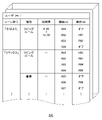
- FIG. 8 is a data structure diagram of the speech setting information 240.
- the utterance setting information 240 is prepared for each user and defines utterance commands corresponding to scenes and operating conditions of various electronic devices 400 corresponding to the utterance commands.
- FIG. 8 shows the speech setting information 240 of the user (P01).
- the speech command defined in advance corresponding to a scene will be referred to as a "scene command”.
- a scene command is identified by a command ID as described above.
- the name registration unit 136 associates and registers command IDs with scene commands such as "relax".
- four types of electronic devices 400 (A01), Electronic device 400 (A02), electronic device 400 (A03), and electronic device 400 (A04) are associated with respective operating conditions.
- the operating condition of electronic device 400 (A01) is "off.” Therefore, when the user (P01) speaks "good morning” in the living room during the above time period, the device control unit 226 powers off the electronic device 400 (A01). For example, when electronic device 400 (A01) is a "lighting device", device control unit 226 sets the lighting device to the off state.
- Action ID is associated with the action condition in advance.
- the device control unit 226 associates and registers the operation ID and the contents of the operation condition in advance.
- an operating condition (R01) is set for the electronic device 400 (A02).
- electronic device 400 (A02) is an air conditioner and the operating condition (R01) is "perform dehumidification for 10 minutes and set the temperature to 25 degrees".
- the device control unit 226 instructs the air conditioner to "dehumidify for only 10 minutes and set the temperature to 25 degrees.” Instruct setting.
- the integrated terminal 100 simultaneously and automatically controls the four types of electronic devices 400 when the user (P01) speaks "good morning” in the living room during the above time period.
- the integrated terminal 100 When the user (P01) says “good morning” outside of the above time period "4:00 to 10:00", the integrated terminal 100 does not perform any special processing. This is because the utterance setting information 240 does not define the control of the electronic device 400 at this time. Also, when the user (P01) speaks "good morning” outside the living room, the integrated terminal 100 does not perform any special processing.
- the device control unit 226 controls the electronic device 400 (A01) according to the operating conditions (R03) regardless of the utterance time period.
- the electronic device 400 (A01) may be "lighting device” and the operating condition (R03) may be "turn on at 20% illuminance”.
- device control unit 226 controls electronic device 400 (A02), electronic device 400 (A03), and electronic device 400 (A04) according to operating conditions (R01), operating conditions (R04), and operating conditions (R05), respectively. Control.
- the device control unit 226 controls the electronic device 400 (A05), the electronic device 400 (A06), and the electronic device 400 (A07).
- the utterance setting information 240 which electronic device 400 the device control section 226 controls and how is defined according to the user, scene command (command ID), place, and time period.
- the operating conditions are defined as whether dehumidification is required, the set temperature, the wind direction, the wind volume, and the like. If the electronic device 400 is a "window” that can be electrically controlled, unlocking and locking, the degree of opening of the window, etc. are defined as operating conditions. As the electronic device 400, in addition to this, an electric curtain, a television, an audio device, a lighting device, and the like are assumed.
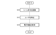
- FIG. 9 is a flow chart showing the process when a speech command is detected.
- the user (P01) enters the living room during the time period of "4:00 to 10:00" and says “Good morning” (see also FIG. 8).
- the user identification unit 218 has grasped the user IDs of all persons in the living room. Since there may be multiple occupants in the living room, it is necessary to identify the speaker when responding to the scene command "good morning".
- the speech recognition unit 220 collects sound with a microphone, recognizes the utterance command "Good morning", and identifies the command ID. That is, the voice recognition unit 220 recognizes the scene command (S10). Next, the speech recognition unit 220 identifies the speaker's user ID based on the features of the speech (S12). Specifically, the speaker is identified from among the one or more people in the room by comparing the voice features of the one or more people in the room identified by the user identification unit 218 and the voice features of the scene command. When there is only one person in the room, the voice recognition unit 220 identifies the only person in the room as the speaker without performing voice verification processing.
- the device control unit 226 refers to the speech setting information 240, specifies the electronic device 400 to be controlled, and controls each electronic device 400 according to the operating conditions of each specified electronic device 400 (S14).
- the integrated terminal 100 simultaneously controls the multiple electronic devices 400 by transmitting control signals to each of the multiple electronic devices 400 .
- Integrated terminal 100 may transmit a control signal to electronic device 400 by LTE (Long Term Evolution).
- the integrated terminal 100 may directly transmit a control signal to the electronic device 400 by a short-range wireless communication method such as Bluetooth (registered trademark), or relay a control signal between a plurality of electronic devices 400 to transmit a plurality of electronic devices.
- a control signal may be sent to the device 400 .
- the relay method will be described later with reference to FIG.
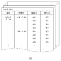
- FIG. 10 is a data structure diagram of the lifestyle information 250.
- the lifestyle information management unit 230 detects the behavior of the user through various sensors installed indoors and outdoors, such as a camera, a motion sensor, a microphone, a LiDAR, and a thermosensor, and registers the user's lifestyle as the lifestyle information 250.
- Life information 250 is prepared for each user and records the operating conditions of each electronic device 400 according to the time period and location.
- FIG. 10 shows the life information 250 of the user (P01) on May 26 (Wednesday). Life information is information similar to the usage history in the first embodiment.
- the user (P01) is in the living room, and the electronic device 400 (A01) is turned off at this time. ing.
- the electronic device 400 (A01) may be turned off automatically by the device control unit 226 (described later), or may be voluntarily turned off by the user (P01) according to a scene command or an instruction from the user terminal 300. There is also sex.
- the electronic device 400 (A02) is controlled according to the operating conditions (R01).
- the operating conditions (R01) of the electronic device 400 (A02) may also be automatically set by the device control unit 226 or set by the user (P01).
- the device control unit 226 responds to the set operating conditions. to assign a new action ID.
- the lifestyle information management unit 230 appropriately records the lifestyle information 250 by detecting the location and time zone of each user and the operating conditions of the electronic device 400 at that time.
- the receiver 212 of the integrated terminal 100 periodically receives the current operating conditions from the electronic device 400 .
- FIG. 11 is a data structure diagram of the basic setting information 260.
- the basic setting information 260 is prepared for each user and defines operating conditions of the electronic device 400 that are considered appropriate for the user according to the time zone and location.
- Device control section 226 generates basic setting information 260 based on life information 250 . For example, when the user (P01) is in the living room during the time period "6:30-7:00", there is a 70% chance that the TV is on and a 30% chance that it is not. In this case, the device control section 226 sets the operating conditions of the basic setting information 260 so that the television (electronic device 400) is turned on. Also, when the television is turned on, if the possibility of watching television on the channel of television station B is higher than that of other television stations, the device control unit 226 sets the operating conditions of the basic setting information 260 so that the channel is set to television station B. do.
- the device control unit 226 selects the “operating conditions with the highest possibility of selection” for each electronic device 400 for each user, time period, and location, such as opening and closing of curtains and set temperature of the air conditioner. It is defined in the basic setting information 260 .
- basic setting information 260 defines operating conditions of electronic device 400 that best suit the user's lifestyle.
- a set of operating conditions for each electronic device 400 defined by the basic setting information 260 will be referred to as a "comfortable environment".
- the device control unit 226 controls the electronic device 400 (A01), Electronic device 400 (A02), electronic device 400 (A03), and electronic device 400 (A04) are automatically controlled. For this reason, the user (P01) can be provided with a comfortable environment suitable for his/her usual lifestyle just by entering the living room without giving various instructions such as turning on the TV, opening the curtains, or turning on the air conditioner. be.
- the device control unit 226 controls the electronic device 400 according to the utterance setting information 240.
- the control contents (operating conditions) of electronic device 400 are recorded in life information 250 by life information management unit 230 .
- the device control section 226 appropriately updates the basic setting information 260 according to the living information 250 .
- the integrated terminal 100 can flexibly change the basic setting information 260 according to instructions from the user while providing the user with a comfortable environment according to the basic setting information 260 .
- the device control unit 226 may define the basic setting information 260 based on conditions other than the time zone and location. For example, it detects whether or not the user (P01) is sitting at a desk, or whether or not the user (P01) is wearing clothes, etc. by image recognition. operating conditions may be varied.
- Life information management unit 230 records such a lifestyle in life information 250 .
- the device control unit 226 registers "song C" in the basic setting information 260 as an audio operating condition. In this case, when it is detected that the user has sat down at the desk in the study, the device control unit 226 turns on the power of the audio in the study, and automatically plays music C or music of the same genre as music C. good too.
- the basic setting information 260 is a file that defines an environment in which the user feels comfortable. A comfortable environment can be prepared automatically.
- FIG. 12 is a flow chart showing the process when the user wakes up and enters the living room.
- the presence detection unit 222 detects presence (entry) of the user (P01) by a human sensor installed in the living room (S20).
- the device control unit 226 refers to the basic setting information 260 and controls the electronic device 400 (S24). At the same time, the lifestyle information management unit 230 records the lifestyle information 250 of the user (P01).
- the speech recognition unit 220 identifies that the speaker is the user (P01) and identifies words such as “slightly” and “hot” (S28).
- the device control unit 226 associates "hot” with the operating condition “lower the temperature of the air conditioner” in advance. "Slightly” is associated with “once” in advance.
- the device control unit 226 detects that the user (P01) said “it's a little hot", it lowers the set temperature of the air conditioner by 1 degree (S30).
- the device control unit 226 appropriately changes the operating conditions of the electronic device 400 according to the user's utterance (utterance command).
- the device control unit 226 changes the set temperature of the air conditioner from “25 degrees” to “24 degrees”.
- the lifestyle information management unit 230 updates the lifestyle information 250 according to the change in the set temperature.
- the device control unit 226 also changes the set temperature of the air conditioner in the basic setting information 260 to "24 degrees” according to the updated lifestyle information 250 (S32).
- the integrated terminal 100 automatically sets the air conditioner to "25 degrees” in accordance with the lifestyle of the user (P01), and when the user feels hot, the integrated terminal 100 turns off the air conditioner.
- the set temperature is lowered and the user's (P01) comfortable temperature (set temperature of the air conditioner defined in the basic setting information 260) is changed from “25 degrees” to "24 degrees". Therefore, when the user (P01) comes to the living room the next morning, the device control unit 226 sets the air conditioner to "24 degrees" according to the basic setting information 260 after the update.
- the basic setting information 260 is not necessarily updated immediately. For example, if the comfortable temperature is "25 degrees” and the setting is changed to “24 degrees” only once, "24 degrees” may not always be the comfortable temperature. On the other hand, when the comfort temperature is set to "25 degrees” and the setting temperature is repeatedly instructed to be changed to "24 degrees", the device control unit 226 changes the comfort temperature of the basic setting information 260 to "24 degrees". Again. As described above, the device control unit 226 refers to the vast amount of living information 250 and registers the "setting temperature with the highest possibility of selection" in the basic setting information 260 as the comfortable temperature.
- the life information management unit 230 may update the life information 250 according to the user's (P01) speech command, and the device control unit 226 may update the basic setting information 260 as the life information 250 is updated. Alternatively, the device control section 226 may immediately update the basic setting information 260 based on the speech command of the user (P01). For example, when the comfortable temperature is "25 degrees" and the user (P01) says “it's a little hot", the device control unit 226 may immediately set the comfortable temperature to "24 degrees".
- the device control unit 226 When the device control unit 226 detects the user's utterance "It's a little hot” when the outside temperature is low, the room temperature may be lowered by opening the windows instead of the air conditioner. Further, when the outside air temperature is higher than the room temperature by a predetermined value or more and the user's utterance "it's a little hot” is detected, the temperature of the air conditioner may be lowered while the window is closed. When the user's utterance "it's very hot” is detected, the device control unit 226 may lower the set temperature of the air conditioner by 2 degrees.
- the method of controlling electronic device 400 in response to the user's (P01) speech command can be arbitrarily set.
- the integrated terminal 100 automatically prepares a comfortable environment for the user (P01) according to the basic setting information 260.
- the integrated terminal 100 appropriately updates the basic setting information 260 based on the speech command of the user (P01) or the operation from the user terminal 300.
- FIG. The user can naturally change and adjust the “comfortable environment” through speech commands or control of the electronic device 400 by the user terminal 300 .
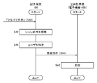
- FIG. 13 is a flow chart showing the process when the user goes to work by car. It is assumed that the user (P01) issues a scene command "go out by car" (S40). The voice recognition unit 220 recognizes the scene command and identifies the command ID (S42). The speech recognition unit 220 identifies that the speaker is the user (P01) (S44). The device control unit 226 refers to the utterance setting information 240 of the user (P01) and specifies the operating conditions of the electronic device 400 corresponding to the scene command "go out by car". Here, the scene instruction "go out by car” is associated with the elevation of the parking structure (electronic device 400).
- the transmission unit 210 of the integrated terminal 100 transmits a step-up instruction designating the vehicle storage position to the parking structure (electronic device 400) (S46).
- the transmission unit 210 transmits the step-up instruction to the multi-storey parking lot by LTE.
- the multi-storey parking lot raises a pallet, which is a pedestal on which the car is placed, so that the car can leave from the specified vehicle position (S48).
- the integrated terminal 100 causes the multi-story parking lot to start preparations for leaving the car.
- the user (P01) can leave the car immediately after arriving at the multi-storey car park without having to wait for the pallet to go up next to the multi-storey car park.
- the device control unit 226 of the integrated terminal 100 may additionally instruct the automobile (electronic device 400) to start the engine and start the cooling when the outside air temperature is equal to or higher than a predetermined temperature when the scene command "go out by car” is recognized.
- the device control unit 226 instructs the parking structure to descend. Specifically, when the position detection unit 214 detects that the vehicle has sufficiently left the parking structure, the device control unit 226 may transmit a descending instruction to the parking structure.
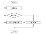
- FIG. 14 is a flow chart showing the process when the user leaves the living room.
- the presence detection unit 222 can detect the leaving of the user (P01).
- the device control section 226 sets a timer. The timer is set for 20 minutes, for example. Here, it is assumed that the last person to leave the living room is the user (P01).
- the process shown in FIG. 14 is started.
- the transmission unit 210 transmits a confirmation notification to the user (P01) (S50).
- the confirmation notification here is an inquiry for confirming whether the user (P01) has temporarily left the living room or will not return for a while. If the user (P01) intends to leave temporarily, the user (P01) operates the user terminal 300 to send a reply indicating "temporary leave" to the integrated terminal 100. FIG. If it is a temporary leave (Y of S52), the timer is reset to 10 minutes (S54). If none of the users return to the living room within 10 minutes after the "temporary exit” notification, the process of FIG. 14 is re-executed.
- the device control unit 226 When there is no reply indicating "temporary withdrawal” from the user (N of S52), the device control unit 226 powers off all the electronic devices 400 in the living room (S56). That is, when the user does not return to the living room after leaving the living room, the device control unit 226 turns off all the electronic devices 400, thereby preventing power consumption.
- the device control unit 226 may not only turn off the power of the electronic device 400, but also shift the electronic device 400 to the power saving mode.
- the power saving mode referred to here may be any operating mode capable of suppressing power consumption more than during normal operation.
- a television may be in a standby mode, and a lighting device may be in a mode in which the illuminance is suppressed more than usual.
- off process the process of turning off the power of the electronic device 400 or shifting to the power saving mode as shown in S56 will be collectively referred to as "off process".
- the device control unit 226 may check the occupancy of each room, not limited to the living room. In addition, when the user is not detected inside the house, the appliance control section 226 may perform the off process for all the electronic appliances 400 inside the house. At this time, the device control section 226 may instruct the doors and windows to be locked.
- the confirmation notification in S50 is not essential.
- the device control section 226 may perform the off processing without sending a confirmation notification.
- the device control unit 226 may perform off processing according to the user's (P01) speech command. For example, when the user (P01) issues an utterance command "I'm going out", the device control unit 226 may execute the off process. Also, when the off process is performed, for example, an exceptional process such as turning on only the air conditioner because there is a pet dog may be set in advance.
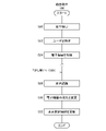
- FIG. 15 is a flow chart showing the process when entry is detected at the entrance.
- the occupancy detection unit 222 detects an event that a person has entered the front door using the human sensor (S60).
- the user identification unit 218 identifies the user ID of the person in the room (the user newly detected to have entered the entrance) (S62).
- the user identification unit 218 identifies the user ID of the person in the room by receiving the user ID from the user terminal 300 owned by the person in the room.
- the user identification unit 218 has set one or more users in advance as "registered users".
- a registered user here is a member who can enter and leave the house freely, for example, a member of a family. If the user is specified (Y of S62) and if the specified user is a registered user (Y of S64), the device control unit 226 controls the electronic device 400 based on the basic setting information 260, A corresponding comfortable environment is prepared (S66).
- the transmission unit 210 transmits a room entry notice to the registered user (S68).
- the room entry notification includes face photo data of the person entering the room.
- the registered user receives the room entry notification from the integrated terminal 100 using the user terminal 300 .
- the registered user When the registered user is not a suspicious person, for example, when the registered user brings a friend who is a non-registered user to his home, the registered user replies with a notification of permission.
- the notification of permission is issued, that is, when the entry is not unauthorized (N of S70)
- the subsequent processing is skipped and the non-registered user is permitted to enter the room.
- the alarm unit 216 transmits an alarm signal to the alarm device (S72).
- the alarm device generates sound and notifies the security company of the intrusion of a suspicious person.
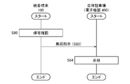
- FIG. 16 is a flow chart showing the process when the user comes home by car.
- the position detection unit 214 detects that the car in which the user (P01) is boarding approaches his home.
- the device control unit 226 confirms with the user (P01) whether or not the user (P01) is scheduled to return home (S80).
- the integrated terminal 100 may start preparing to enter without waiting for confirmation from the user.
- the integrated terminal 100 starts preparing to enter the car. That is, the device control unit 226 transmits a step-up instruction to the parking structure (electronic device 400) (S82). When the multistory parking lot receives the step-up instruction, it steps up the pallet and prepares for the vehicle to enter (S84).
- the integrated terminal 100 when the user (P01) approaches his home, the integrated terminal 100 starts preparing to enter the multi-storey parking lot. No more waiting.
- the device control unit 226 instructs the multi-story parking lot to descend.
- the equipment control unit 226 may transmit a step-down instruction to the parking structure.
- the user terminal 300 may transmit the location information of the user (P01) to the integrated terminal 100.
- the integrated terminal 100 and the user terminal 300 may be notified of status information indicating that the parking structure is entering or exiting the parking lot.
- the multi-storey car park notifies the integrated terminal 300 and the user terminal 300 as state information that the next process can be executed when the work of entering or exiting the parking lot is completed.
- the device control unit 226 may start the entering/exiting instruction when the multi-storey car park is in a state where the next process can be executed.
- FIG. 17 is a data structure diagram of the viewing setting information 270. As shown in FIG. The viewing setting information 270 is prepared for each user, and defines "positive conditions" and "passive conditions" that serve as criteria when the user selects a television program. A positive condition indicates a condition of television programs that the user prefers. A negative condition indicates a condition of a television program that the user does not like.
- “singer Q1" is set as a positive condition for user (P01).
- the program guide acquiring unit 228 acquires a TV program guide from a known web server by searching the Internet. Based on the positive condition, the program proposal unit 224 is likely to propose to the user (P01) a TV program that satisfies the positive condition in the TV program guide, for example, a TV program in which singer Q1 is scheduled to appear.
- Actor Q4" is set as a passive condition for user (P01). Based on the negative condition, it becomes difficult for the program proposal unit 224 to propose to the user (P01) a television program in which actor Q4 is scheduled to appear. More specifically, the program proposal unit 224 sets a recommendation value for each television program. A television program that satisfies more positive conditions has a higher recommendation value, and a television program that satisfies more negative conditions has a lower recommendation value. The program proposal unit 224 calculates a recommendation value for each television program based on the viewing setting information 270 .
- FIG. 18 is a flow chart showing the process when a user who has returned home watches a television program.
- the user who has returned home by car, utters the scene command "relax" in the living room.
- the scene command "relax” is set with the operating condition "turn on the power of the television (electronic device 400)".
- the voice recognition unit 220 recognizes the scene command by voice (S90).
- the program proposal unit 224 selects the television program with the highest recommendation value from among the plurality of television programs currently being broadcast and proposes it to the user (P01) (S94).
- the program proposal unit 224 may make a proposal by voice output, or may transmit information on a recommended TV program to the user terminal 300 (P01).
- the device control unit 226 When the user (P01) approves the proposed TV program (Y of S96), the device control unit 226 powers on the TV and sets the channel to the selected TV program (S98). The user (P01) notifies the integrated terminal 100 of approval or rejection by voice or operation of the user terminal 300.
- the program proposal section 224 proposes a television program with the next highest recommendation value (S94).
- the TV program approved and selected by the user (P01) is recorded in the life information 250 by the life information management unit 230.
- FIG. Based on the life information 250, the device control unit 226 registers the TV programs that the user (P01) prefers in the basic setting information 260.
- the program proposal unit 224 has proposed "professional baseball broadcast” based on the recommendation value of each television program. It is assumed that the user (P01) likes professional baseball, but wants to watch comedy programs rather than professional baseball. At this time, the user (P01) may refuse the "professional baseball broadcast” and wait for the program proposal unit 224 to propose a comedy program, or instruct the integrated terminal 100 to "want to watch a comedy program.” good too.
- the life information management unit 230 records in the life information 250 information that the user (P01) will watch the "comedy program” at 18:15.
- the device control unit 226 updates the basic setting information 260 so that when the user (P01) is in the living room at 18:15, the television is turned on. Set it as a comfortable environment to turn on and set the channel to "comedy program”.
- the user (P01) may set the viewing setting information 270 himself.
- the device control unit 226 may update the viewing setting information 270 based on the cast and genre of the TV program selected by the user (P01). For example, assume that the user (P01) selects a television program in which actor Q4 (passive condition) appears. In this case, it is considered that the user (P01) does not dislike actor Q4 as much as before, so the device control section 226 may exclude actor Q4 from the target of the negative condition.
- the device control section 226 may register singer Q6 in the viewing setting information 270 as a positive condition target.
- a program in which singer Q1 (positive condition) appears is proposed to the user (P01) but is rejected.
- the device control section 226 may exclude singer Q1 from the subject of positive conditions. In this manner, the device control section 226 may update not only the basic setting information 260 but also the viewing setting information 270 as appropriate based on the television program selection history of the user (P01).
- FIG. 19 is a functional block diagram of electronic device 400. As shown in FIG. FIG. 19 shows functional blocks related to control by the integrated terminal 100 among various electronic devices 400 .
- Electronic device 400 includes communication unit 402 , data processing unit 404 and data storage unit 406 .
- the communication unit 402 performs communication processing with the integrated terminal 100 and the user terminal 300 through a wireless communication network or short-range wireless communication.
- a data storage unit 406 stores various information.
- the data processing unit 404 executes various processes based on data acquired by the communication unit 402 and data stored in the data storage unit 406 .
- Data processing unit 404 also functions as an interface for communication unit 402 and data storage unit 406 .
- the communication unit 402 includes a transmission unit 410 that transmits data and a reception unit 408 that receives data.
- the data processing section 404 includes an operation control section 412 and a transfer determination section 414 .
- the operation control unit 412 controls operations of the electronic device 400 .
- operation control unit 412 sets the set temperature, dehumidification, wind direction, wind force, etc. of the air conditioner based on control signals from integrated terminal 100 .
- the transfer determination unit 414 determines whether or not to transfer the control signal received from the integrated terminal 100 to another electronic device 400 . The transfer of control signals is described in detail in connection with FIG. 20 below.
- FIG. 20 is a sequence diagram showing a method of transferring control commands by the relay method.
- the integrated terminal 100 may transmit control commands to the plurality of electronic devices 400 by LTE, or may transmit control commands to the electronic devices 400 by short-range wireless communication such as Bluetooth (registered trademark).
- short-range wireless communication such as Bluetooth (registered trademark).
- a “relay system” is adopted in order to ensure that each electronic device 400 receives the control command.
- a “relay system” for example, a "multi-hop communication function" in a wireless communication system may be used.
- the device control unit 226 of the integrated terminal 100 refers to the basic setting information 260 and multicasts (simultaneously distributes) the control command 1 (denoted as "command 1" in FIG. 20) by short-range wireless communication (S102).
- the control command includes a command ID for identifying the control command, the device ID of electronic device 400 to be controlled, and operating conditions.
- the term "multicast” as used herein refers to transmission of a control command within a predetermined range without specifying a receiving destination.
- the microwave oven electronic device 400
- the microwave oven multicasts the control instruction 1 as it is without performing any particular operation control because the control instruction 1 is not intended for the microwave oven itself (S104).
- the integrated terminal 100 receives the control command 1 from the microwave oven, but does not transfer (multicast) it.
- the refrigerator also receives the control command 1 transmitted from the microwave oven.
- the refrigerator multicasts control instruction 1 without performing any particular operation control because control instruction 1 is not intended for its own device.
- the microwave oven receives the control command 1 transferred from the refrigerator.
- Microwave oven 414 checks the command ID included in control command 1, and if it is a control command that has already been received, it does not perform any more multicasting. Since control instruction 1 is the control instruction that the microwave oven has received and has previously multicast, the microwave oven does not perform any more multicasts.
- the air conditioner receives control command 1 sent by the refrigerator.
- the control command 1 designates the air conditioner by the device ID. Assume that the control command 1 sets an operating condition to lower the set temperature of the air conditioner.
- the operation control unit 412 of the air conditioner lowers the set temperature according to the control command 1 (S108).
- Control instruction 1 is a control instruction for changing the set temperature of the air conditioner in advance to a lower temperature than usual because it is assumed that the room temperature will rise when cooking starts.
- the air conditioner also forwards the control command 1.
- the refrigerator receives control command 1, but since it has already received it, it does not perform any further transfers.
- the transmission unit 410 of the microwave oven transmits the command ID and the control command 2 designating to lower the power of the refrigerator and the air conditioner (S114).
- the integrated terminal 100 receives the control command 2 but does not transfer (multicast) it.
- the refrigerator receives the control command 2 and reduces the power (S116).
- the forwarding determination unit 414 of the refrigerator determines that the multicast is necessary because the control command 2 is received for the first time, and the transmitting unit 410 of the refrigerator multicasts the control command 2 (S118).
- the microwave oven receives control command 2, but since control command 2 has already been received, no further transfer is performed.
- the air conditioner receives control command 2 and reduces power (S120).
- the transmitter 410 of the air conditioner multicasts the control command 2 . Since the refrigerator has already received the control command 2, no further transfer is performed. According to this control method, the refrigerator and the air conditioner can autonomously reduce power consumption in preparation for an increase in power consumption by the microwave oven when cooking is started in the microwave oven.
- the electronic device control method by the electronic device integration system 200 has been described above based on the embodiment.
- the user can collectively control a plurality of electronic devices 400 using the user terminal 300 .
- integrated terminal 100 can operate electronic device 400 with optimal settings for the user at startup.
- the integrated terminal 100 can change the optimum settings of the electronic device 400 by informing the integrated terminal 100 of changes in setting values and wishes of the user. Therefore, even if the electronic device 400 has various parameters, the integrated terminal 100 can appropriately control the electronic device 400 based on the usage history and the user's wishes.
- the user can register the new electronic device 400 in the device list by the integrated terminal 100 simply by activating the electronic device 400 with the remote controller. Similarly, a boot interface for the new electronic device 400 is added to the user terminal 300 . Therefore, it is possible to reduce the troublesomeness associated with the introduction and setting of the electronic device 400 .
- the user's lifestyle generally has a certain degree of stability (pattern).
- the lifestyle information management unit 230 of the integrated terminal 100 records the lifestyle of each user as the lifestyle information 250 based on the behavior of the user, and the device control unit 226 creates basic setting information 260 based on the lifestyle information 250 .
- Basic setting information 260 defines a "comfortable environment" that matches the lifestyle of the user. For example, some people turn on the TV while they work, while others do not.
- the integrated terminal 100 in the second embodiment can preemptively set a comfortable environment suitable for the user according to the user's lifestyle.
- the user can freely intervene in the provision of a comfortable environment based on the basic setting information 260 through the user terminal 300 or voice utterance. Since the basic setting information 260 is appropriately updated based on the life information 250, the user can obtain a comfortable environment with a minimum of operations and instructions.
- the integrated terminal 100 in the second embodiment can receive instructions from the user, but basically functions as a "butler" that casually creates a comfortable environment for the user.
- the integrated terminal 100 does not have to be connected to the Internet.
- the integrated terminal 100 may be configured to communicate only with nearby user terminals 300 or electronic devices 400 via short-range wireless communication such as Bluetooth®. In the case of such a configuration, it is possible to reduce the risk that the user's privacy information (basic setting information 260, etc.) held by the integrated terminal 100 is leaked to the outside via the Internet.
- the integrated terminal 100 automatically turns off the electronic device 400 when the user leaves a space such as a living room. Turning off electronic device 400 by integrated terminal 100 not only reduces power consumption but also contributes to safe operation of electronic device 400 .
- the integrated terminal 100 according to the second embodiment can reduce the waiting time in the multi-storey car park by giving advance instructions for ascending and descending steps in the multi-storey car park.
- the integrated terminal 100 can actively propose TV programs that suit the user's taste based on the viewing setting information 270.
- the user can have the integrated terminal 100 set a TV program that suits his/her taste simply by issuing a scene command such as "relax" or by simply entering the living room.
- the life information management unit 230 of the integrated terminal 100 records the experience of the user in the life information 250 .
- the device control unit 226 of the integrated terminal 100 generates basic setting information 260 indicating a comfortable environment for the user based on the life information 250 .
- the integrated terminal 100 controls each electronic device 400 based on the basic setting information 260 .
- Such a configuration makes it easier for the integrated terminal 100 to always appropriately propose a “comfortable environment at that time” based on the user's experience.
- each electronic device 400 may manage its own usage history.
- electronic device 400 includes a usage history management unit that manages the usage history of the device for each user, an activation reception unit that receives an activation signal from user terminal 300 or a remote controller, and an activation signal that is automatically received when the activation signal is received.
- a start-up control unit that starts the device and a setting unit that initially sets operating conditions of the device may be provided.
- the communication unit of the air conditioner may transmit designation information of the air conditioner to the integrated terminal 100, and the integrated terminal 100 may register the air conditioner in the device list based on this designation information. Also, the integrated terminal 100 may generate an operation screen 310 including an air conditioner activation interface and provide it to the user terminal 300 .
- each electronic device 400 may notify the integrated terminal 100 of the usage history information. According to such a control method, even if the integrated terminal 100 fails, each electronic device 400 backs up the usage history information, so the service by the integrated terminal 100 can be continued promptly.
- the electronic device 400 When the electronic device 400 manages the usage history, first, the user terminal 300 transmits the second activation signal to the integrated terminal 100 , and the integrated terminal 100 transmits the first activation signal to the electronic device 400 .
- the setting unit of electronic device 400 refers to the usage history and sets the operating conditions of its own device. The setting result may be transmitted to the user terminal 300 via the integrated terminal 100 .
- Electronic device 400 may transmit a URL (Uniform Resource Locator) of a web page for controlling itself to user terminal 300 .
- the user can change the setting values of the electronic device 400 by accessing the designated URL from the user terminal 300 .
- the usage history management unit of electronic device 400 updates the usage history information along with the setting change.
- the user terminal 300 may store various personal information about the user.
- the user terminal 300 may provide all or part of this personal information to the integrated terminal 100, and the integrated terminal 100 may change the settings of the electronic device 400 based on the personal information as well as the usage history. For example, if user P1 likes to travel, integrated terminal 100 may tune in to a travel program when the television is turned on. If user P2 recently played shogi, integrated terminal 100 may tune in to a shogi program when the television is started. If user P3 has hay fever, integrated terminal 100 may activate the air purifier when the user returns home when the pollen warning is issued. By deeply analyzing the user's personal information in this way, the integrated terminal 100 can control the plurality of electronic devices 400 at a higher level.
- the integrated terminal 100 activates "air conditioner” and "TV".
- the air conditioner determines the setting value based on the usage history.
- the television sets its own settings (eg, channel) based on the usage history.
- the integrated terminal 100 generates the operation screen 310 and the user terminal 300 displays the operation screen 310 using the web browser.
- the user terminal 300 may include an operation screen generator.
- the operation screen generation unit of user terminal 300 may generate operation screen 310 including an "air conditioner” button.
- a second activation signal including an ID corresponding to the air conditioner may be transmitted from the user terminal 300 to the integrated terminal 100 when the user touches the “air conditioner” button.
- the utterance setting information 240 sets the operating conditions of the electronic device 400 according to the location and time in addition to the scene command.
- the life information 250 also records the operating state of the electronic device 400 according to the location and time. The same applies to basic setting information 260 .
- the operating conditions of the electronic device 400 may be set according to the user's situation.
- the device control unit 226 captures an image of the user with a camera, and "is working (operating a PC at the table)", “cooking”, or “relaxing (sitting on the sofa)".
- the operating conditions of electronic device 400 may be set according to the user's behavior.
- the device control unit 226 may turn off the television when the user (P01) is working in the living room in the morning, and turn on the television when the user (P01) is relaxing in the living room in the morning. .
- the integrated terminal 100 may control the electronic device 400 based not only on the behavior of the user, but also on the user's physical condition or emotion.
- the method of controlling electronic device 400 may be changed based on the user's breathing sound, amount of heat generation, presence or absence of coughing, facial expression, volume and tone of voice, and the like.
- the life information management unit 230 records life information 250 for each of various items such as location, time, behavior, and physical condition.
- Device control unit 226 generates basic setting information 260 based on life information 250 . According to such a control method, it is possible to provide a more suitable comfortable environment according to the user's situation.
- Priority may be set in advance for users. For example, assume that user (P01) and user (P02) are in the living room at the same time. User (P01) has a higher priority than user (P02).
- the device control section 226 of the integrated terminal 100 may control each electronic device 400 according to the basic setting information 260 of the user (P01).
- the device control section 226 may set a comfortable environment intermediate between the comfortable environments of the user (P01) and the user (P02) as the comfortable environment of the two. For example, when the user (P01) prefers "25 degrees" as the set temperature of the air conditioner and the user (P02) prefers "23 degrees", the device control unit 226 sets the air conditioner to the average value of "24 degrees". It may be the temperature.
- the integrated terminal 100 may be a box-shaped device installed indoors, or a device such as the user terminal 300 that can be carried by an individual.
- Integrated terminal 100 may be configured as a wearable terminal such as an earring, an accessory, or a watch.
- the speech recognition unit 220 extracts words by speech recognition from free utterances such as "It's hot”, “Isn't it hot”, “I want to wake you up”, and the electronic device 400 and The device controller 226 may control the electronic device 400 according to the operating conditions.
- the user may directly give a voice instruction to operate the electronic device 400 without being limited to the scene instruction.
- device control unit 226 may turn on the air conditioner (electronic device 400).
- the life information management unit 230 updates the life information 250
- the device control unit 226 updates the basic setting information 260 as the life information 250 is updated.
- the device control unit 226 may control the electronic device 400 based on the cancel statement. For example, when the device control unit 226 turns on the television based on the basic setting information 260, the user (P01) says “You don't have to turn on the television.” At this time, the voice recognition unit 220 recognizes "TV” and “not turn on (turn off)", and the device control unit 226 turns off the power of the TV according to the recognition result. At this time, the life information management unit 230 records in the life information 250 that the television is turned off.
- the device control unit 226 may update the utterance setting information 240 when a cancel utterance is made in response to a scene command. For example, it is assumed that the utterance setting information 240 is set to fully open the electric window (electronic device 400) when the user (P03) utters the scene command "good morning.” It is assumed that the user (P03) utters a cancel utterance of 'Don't open the window' within a predetermined time period, for example, within 20 seconds after uttering the scene command 'good morning'. At this time, the device control unit 226 stops the window opening operation. When the window has already been opened, the device control section 226 instructs the window to close.
- the device control unit 226 updates the speech setting information 240, and deletes the "open window operation" in response to the scene command "good morning” of the user (P03). According to such a control method, the user (P03) can freely change the content of the scene command "good morning” by voice.
- the device control unit 226 instructs the opening operation of the window (electronic device 400).
- the device control unit 226 may update the utterance setting information 240 and add "window opening operation" to the scene command "good morning” of the user (P04).
- FIG. 21 is a schematic diagram for explaining an inrush current.
- the horizontal axis indicates time, and the vertical axis indicates the current value flowing through the power line to which the electronic device 400 is connected.
- FIG. 21 shows a current change when an electronic device 400 (A10) is instructed to be turned on at time t1.
- the current value (hereinafter referred to as "normal current value") in the normal mode of electronic device 400 (A10), in other words, during normal operation, is I2.
- I2 current larger than the normal current value I2 may temporarily flow. This is called inrush current.
- the current value is temporarily I3 (>I2) immediately after it is turned on.
- I3 I2
- inrush current There are various causes of inrush current. For example, immediately after turning on, it is necessary to charge the capacitor of the smoothing circuit incorporated in electronic device 400 (A10), and at this time, a large current tends to flow temporarily. When the rush current flows, the operation of other electronic devices 400 connected to the same power supply line as the electronic device 400 (A10) may become unstable. Therefore, suppression of inrush current is an important issue in controlling a large number of electronic devices 400 . In particular, the peak value of the inrush current tends to increase as the electronic device 400 normally has a higher current value.
- the electronic device 400 (A10) shown below has a standby mode, a normal mode, and an intermediate mode (power saving mode) that operates at a current value lower than the normal current value.
- the standby mode indicates a state in which an instruction from integrated terminal 100 can be received, but electronic device 400 (A10) itself is not operating.
- the current value in standby mode (hereinafter referred to as "standby current value") is very small.
- the intermediate mode is a mode in which the electronic device 400 (A10) operates in a power-saving manner by partially limiting the functions of the electronic device 400 (A10) compared to the normal mode.
- electronic device 400 (A10) is an air conditioner
- intermediate mode may be set as a mode in which air blowing is possible but cooling is not in operation.
- the intermediate mode of the air conditioner may be set as a mode in which cooling is possible but only a temperature setting of 22 degrees or higher is permitted.
- FIG. 22 is a schematic diagram showing changes in current when electronic device 400 is turned off.
- the user issues an off instruction at time t1 to electronic device 400 (A10) operating in the normal mode, targeting electronic device 400 (A10).
- the normal current value is I2.
- integrated terminal 100 changes electronic device 400 (A10) from the normal mode to the intermediate mode instead of from the normal mode to the standby mode.
- the value of current flowing through electronic device 400 (A10) in the intermediate mode (hereinafter referred to as "intermediate current value”) is I1.
- the intermediate current value I1 is larger than the standby current value and smaller than the normal current value I2.
- an instruction from integrated terminal 100 to electronic device 400 to switch from the normal mode to the intermediate mode will be referred to as an "intermediate OFF instruction".
- activation transmission section 112 of integrated terminal 100 transmits an intermediate off instruction to electronic device 400 (A10).
- the mode of electronic device 400 (A10) is changed from the normal mode to the intermediate mode when receiving the intermediate off instruction from integrated terminal 100 .
- integrated terminal 100 turns on electronic device 400 (A10).
- electronic device 400 (A10) is changed from the intermediate mode to the normal mode. Since the current change when changing from the intermediate mode to the normal mode is smaller than the current change when changing from the standby mode to the normal mode, the rush current is also suppressed.
- the activation transmission unit 112 of the integrated terminal 100 transmits an OFF instruction to the electronic device 400 (A10) at time t2.
- electronic device 400 (A10) changes from the intermediate mode to the standby mode.
- FIG. 23 is a flow chart showing the process of integrated terminal 100 when electronic device 400 is turned on.
- electronic device 400 (A10) is connected to a single power supply line together with a plurality of electronic devices 400 .
- integrated terminal 100 executes the process shown in FIG. It is also assumed that electronic device 400 (A10) is in standby mode.
- the current confirmation unit (not shown) of the integrated terminal 100 confirms the current value of the power line to which the electronic device 400 (A10) is connected when the ON instruction is received (S130).
- the current confirmation unit may acquire the current value from, for example, an ammeter (not shown) connected to the power supply line.
- a permissible value L is set for the current value flowing through the power line.
- the activation transmission unit 112 of the integrated terminal 100 transmits an ON instruction to the electronic device 400 (A10), and causes the electronic device 400 (A10) to operate normally.
- mode is set (S134). This is because when the value of the current flowing through the power line is sufficiently small, the other electronic devices 400 will not be adversely affected even if a rush current occurs.
- the activation transmission unit 112 sets the electronic device 400 (A10) to the intermediate mode (S136).
- the current value flowing through the power line is large, the rush current is suppressed by changing the electronic device 400 (A10) from the standby mode to the intermediate mode.
- Integrated terminal 100 switches to normal mode after a predetermined period of time has elapsed after switching to intermediate mode.
- electronic device 400 may automatically switch to the normal mode when a predetermined period of time has elapsed after switching to the intermediate mode.
- Device control section 226 of integrated terminal 100 may confirm the current mode of electronic device 400 (A10) by inquiring electronic device 400 (A10).
- integrated terminal 100 when the user transmits an off instruction to integrated terminal 100, integrated terminal 100 temporarily sets electronic device 400 (A10) to intermediate mode, and then sets it to standby mode. In addition, the user may freely select between the off instruction and the intermediate off instruction.
- integrated terminal 100 changes electronic device 400 (A10) to the standby mode.
- integrated terminal 100 may change electronic device 400 (A10) to the intermediate mode.
- the activation transmission unit 112 of the integrated terminal 100 may set the mode of the electronic device 400 (A10) based on the lifestyle of the user indicated in the lifestyle information 250. Assume that the user (P01) instructs to turn off the electronic device 400 (A10). Activation transmission unit 112 refers to life information 250, and if user (P01) is likely to go out during a time period (for example, the possibility of being abroad is 80(%) or more), electronic device 400 (A10) waits. mode. On the other hand, if the possibility of the user (P01) going out is low, activation transmission section 112 may set electronic device 400 (A10) to the intermediate mode to prepare for another turn-on instruction.
- integrated terminal 100 When integrated terminal 100 receives the off instruction from user (P01), it sets electronic device 400 (A10) to the intermediate mode, refers to life information 250, and determines the time when user (P01) is likely to go out.
- the electronic device 400 (A10) may be set to the standby mode when the band is reached.
- the integrated terminal 100 may always set the electronic device 400 (A10) to the intermediate mode and then to the standby mode.
- a plurality of intermediate modes may be set between the standby mode and the normal mode. Between the normal current value and the standby current value, the first intermediate mode to the nth intermediate mode corresponding to the first intermediate current value, the second intermediate current value, . . .
- integrated terminal 100 changes electronic device 400 from the normal mode to the first intermediate mode, after a predetermined period of time, changes from the first intermediate mode to the second intermediate mode, and finally switches to standby mode after a plurality of stages. You can change it.
- integrated terminal 100 may change electronic device 400 from standby mode to n-th intermediate mode, and finally change to normal mode through a plurality of stages.
Landscapes
- Engineering & Computer Science (AREA)
- Automation & Control Theory (AREA)
- Computer Networks & Wireless Communication (AREA)
- Signal Processing (AREA)
- Human Computer Interaction (AREA)
- Selective Calling Equipment (AREA)
- Telephone Function (AREA)
- Telephonic Communication Services (AREA)
Priority Applications (3)
| Application Number | Priority Date | Filing Date | Title |
|---|---|---|---|
| US18/578,078 US20240333550A1 (en) | 2021-07-12 | 2022-05-25 | Electronic device controller, communication terminal, and electronic device |
| JP2023535160A JPWO2023286458A1 (cg-RX-API-DMAC7.html) | 2021-07-12 | 2022-05-25 | |
| TW111120392A TW202325034A (zh) | 2021-07-12 | 2022-06-01 | 電子機器控制裝置、通信終端及電子機器 |
Applications Claiming Priority (2)
| Application Number | Priority Date | Filing Date | Title |
|---|---|---|---|
| JP2021-114857 | 2021-07-12 | ||
| JP2021114857 | 2021-07-12 |
Publications (1)
| Publication Number | Publication Date |
|---|---|
| WO2023286458A1 true WO2023286458A1 (ja) | 2023-01-19 |
Family
ID=84919966
Family Applications (1)
| Application Number | Title | Priority Date | Filing Date |
|---|---|---|---|
| PCT/JP2022/021336 Ceased WO2023286458A1 (ja) | 2021-07-12 | 2022-05-25 | 電子機器制御装置、通信端末および電子機器 |
Country Status (4)
| Country | Link |
|---|---|
| US (1) | US20240333550A1 (cg-RX-API-DMAC7.html) |
| JP (1) | JPWO2023286458A1 (cg-RX-API-DMAC7.html) |
| TW (1) | TW202325034A (cg-RX-API-DMAC7.html) |
| WO (1) | WO2023286458A1 (cg-RX-API-DMAC7.html) |
Cited By (3)
| Publication number | Priority date | Publication date | Assignee | Title |
|---|---|---|---|---|
| WO2024195483A1 (ja) * | 2023-03-22 | 2024-09-26 | ソニーグループ株式会社 | 情報処理装置、方法、およびプログラム |
| WO2025204170A1 (ja) * | 2024-03-26 | 2025-10-02 | パナソニックIpマネジメント株式会社 | 情報処理方法、情報処理装置、情報処理プログラム |
| WO2026133172A1 (zh) * | 2024-12-18 | 2026-06-25 | 大金工业株式会社 | 语音控制方法、装置、设备、系统、存储介质和程序产品 |
Citations (8)
| Publication number | Priority date | Publication date | Assignee | Title |
|---|---|---|---|---|
| JPH11280282A (ja) * | 1998-03-30 | 1999-10-12 | Fuji Electric Co Ltd | 立体駐車場の入庫・出庫準備システム |
| JP2002044764A (ja) * | 2000-07-26 | 2002-02-08 | Sharp Corp | 双方向リモートコントロールシステムと遠隔制御装置及び被制御装置 |
| WO2006038529A1 (ja) * | 2004-10-01 | 2006-04-13 | Matsushita Electric Industrial Co., Ltd. | チャンネル契約提案装置、方法、プログラム及び集積回路 |
| JP2012038109A (ja) * | 2010-08-06 | 2012-02-23 | Panasonic Electric Works Co Ltd | 機器制御システム |
| JP2014225857A (ja) * | 2013-04-18 | 2014-12-04 | 株式会社バッファロー | 通信システム、通信装置、制御方法、および、コンピュータプログラム |
| JP2016206851A (ja) * | 2015-04-20 | 2016-12-08 | シャープ株式会社 | 制御装置、制御装置の制御方法、制御システム、環境制御機器、および制御プログラム |
| WO2020070888A1 (ja) * | 2018-10-05 | 2020-04-09 | 三菱電機株式会社 | 音声操作支援システム、音声操作システム、音声処理装置、音声操作支援装置、音声操作支援方法及びプログラム |
| CN111856956A (zh) * | 2020-07-21 | 2020-10-30 | 青岛海信日立空调系统有限公司 | 一种实现场景互动的控制方法及控制终端 |
Family Cites Families (5)
| Publication number | Priority date | Publication date | Assignee | Title |
|---|---|---|---|---|
| US8042048B2 (en) * | 2005-11-17 | 2011-10-18 | Att Knowledge Ventures, L.P. | System and method for home automation |
| US20140156281A1 (en) * | 2012-12-03 | 2014-06-05 | Qualcomm Incorporated | Voice-controlled configuration of an automation system |
| TW201618049A (zh) * | 2014-11-14 | 2016-05-16 | Univ Nat Kaohsiung 1St Univ Sc | 智慧家庭控制裝置及方法 |
| KR101784990B1 (ko) * | 2016-01-13 | 2017-10-12 | 주식회사 파이브지티 | 얼굴인식을 이용한 홈 오토메이션 제어 시스템 및 그 방법 |
| US11153716B1 (en) * | 2019-01-04 | 2021-10-19 | Alarm.Com Incorporated | Geolocation polling frequency for home automation |
-
2022
- 2022-05-25 JP JP2023535160A patent/JPWO2023286458A1/ja active Pending
- 2022-05-25 US US18/578,078 patent/US20240333550A1/en active Pending
- 2022-05-25 WO PCT/JP2022/021336 patent/WO2023286458A1/ja not_active Ceased
- 2022-06-01 TW TW111120392A patent/TW202325034A/zh unknown
Patent Citations (8)
| Publication number | Priority date | Publication date | Assignee | Title |
|---|---|---|---|---|
| JPH11280282A (ja) * | 1998-03-30 | 1999-10-12 | Fuji Electric Co Ltd | 立体駐車場の入庫・出庫準備システム |
| JP2002044764A (ja) * | 2000-07-26 | 2002-02-08 | Sharp Corp | 双方向リモートコントロールシステムと遠隔制御装置及び被制御装置 |
| WO2006038529A1 (ja) * | 2004-10-01 | 2006-04-13 | Matsushita Electric Industrial Co., Ltd. | チャンネル契約提案装置、方法、プログラム及び集積回路 |
| JP2012038109A (ja) * | 2010-08-06 | 2012-02-23 | Panasonic Electric Works Co Ltd | 機器制御システム |
| JP2014225857A (ja) * | 2013-04-18 | 2014-12-04 | 株式会社バッファロー | 通信システム、通信装置、制御方法、および、コンピュータプログラム |
| JP2016206851A (ja) * | 2015-04-20 | 2016-12-08 | シャープ株式会社 | 制御装置、制御装置の制御方法、制御システム、環境制御機器、および制御プログラム |
| WO2020070888A1 (ja) * | 2018-10-05 | 2020-04-09 | 三菱電機株式会社 | 音声操作支援システム、音声操作システム、音声処理装置、音声操作支援装置、音声操作支援方法及びプログラム |
| CN111856956A (zh) * | 2020-07-21 | 2020-10-30 | 青岛海信日立空调系统有限公司 | 一种实现场景互动的控制方法及控制终端 |
Cited By (3)
| Publication number | Priority date | Publication date | Assignee | Title |
|---|---|---|---|---|
| WO2024195483A1 (ja) * | 2023-03-22 | 2024-09-26 | ソニーグループ株式会社 | 情報処理装置、方法、およびプログラム |
| WO2025204170A1 (ja) * | 2024-03-26 | 2025-10-02 | パナソニックIpマネジメント株式会社 | 情報処理方法、情報処理装置、情報処理プログラム |
| WO2026133172A1 (zh) * | 2024-12-18 | 2026-06-25 | 大金工业株式会社 | 语音控制方法、装置、设备、系统、存储介质和程序产品 |
Also Published As
| Publication number | Publication date |
|---|---|
| TW202325034A (zh) | 2023-06-16 |
| US20240333550A1 (en) | 2024-10-03 |
| JPWO2023286458A1 (cg-RX-API-DMAC7.html) | 2023-01-19 |
Similar Documents
| Publication | Publication Date | Title |
|---|---|---|
| US11671662B2 (en) | Methods and systems for controlling media display in a smart media display environment | |
| JP7719154B2 (ja) | イベントクリップを提供するための、方法、電子装置、サーバシステム、およびプログラム | |
| US12081830B2 (en) | Video integration with home assistant | |
| US6842510B2 (en) | Method of and apparatus for controlling devices | |
| EP3622493B1 (en) | Systems, methods, and devices for activity monitoring via a home assistant | |
| US10028023B2 (en) | Methods and systems for automatic media output based on user proximity | |
| US20240333550A1 (en) | Electronic device controller, communication terminal, and electronic device | |
| WO2014103304A1 (ja) | 制御方法 | |
| JP6140214B2 (ja) | 制御装置、制御装置の制御方法、制御システム、環境制御機器、および制御プログラム | |
| JP4852449B2 (ja) | 住宅内機器制御システム | |
| JP2005333495A (ja) | 電子機器管理ロボット | |
| CN121690881A (zh) | 一种设备控制方法、装置、系统、电子设备及存储介质 |
Legal Events
| Date | Code | Title | Description |
|---|---|---|---|
| 121 | Ep: the epo has been informed by wipo that ep was designated in this application |
Ref document number: 22841805 Country of ref document: EP Kind code of ref document: A1 |
|
| WWE | Wipo information: entry into national phase |
Ref document number: 18578078 Country of ref document: US |
|
| WWE | Wipo information: entry into national phase |
Ref document number: 2023535160 Country of ref document: JP |
|
| NENP | Non-entry into the national phase |
Ref country code: DE |
|
| 122 | Ep: pct application non-entry in european phase |
Ref document number: 22841805 Country of ref document: EP Kind code of ref document: A1 |