WO2023286207A1 - 空気調和機および空気調和機の製造方法 - Google Patents
空気調和機および空気調和機の製造方法 Download PDFInfo
- Publication number
- WO2023286207A1 WO2023286207A1 PCT/JP2021/026474 JP2021026474W WO2023286207A1 WO 2023286207 A1 WO2023286207 A1 WO 2023286207A1 JP 2021026474 W JP2021026474 W JP 2021026474W WO 2023286207 A1 WO2023286207 A1 WO 2023286207A1
- Authority
- WO
- WIPO (PCT)
- Prior art keywords
- air
- air conditioner
- humidity
- suction
- humidity sensor
- Prior art date
- Legal status (The legal status is an assumption and is not a legal conclusion. Google has not performed a legal analysis and makes no representation as to the accuracy of the status listed.)
- Ceased
Links
Images

Classifications
-
- F—MECHANICAL ENGINEERING; LIGHTING; HEATING; WEAPONS; BLASTING
- F24—HEATING; RANGES; VENTILATING
- F24F—AIR-CONDITIONING; AIR-HUMIDIFICATION; VENTILATION; USE OF AIR CURRENTS FOR SCREENING
- F24F11/00—Control or safety arrangements
- F24F11/89—Arrangement or mounting of control or safety devices
-
- F—MECHANICAL ENGINEERING; LIGHTING; HEATING; WEAPONS; BLASTING
- F24—HEATING; RANGES; VENTILATING
- F24F—AIR-CONDITIONING; AIR-HUMIDIFICATION; VENTILATION; USE OF AIR CURRENTS FOR SCREENING
- F24F2110/00—Control inputs relating to air properties
- F24F2110/20—Humidity
Definitions
- the present invention relates to an air conditioner and an air conditioner manufacturing method, and more specifically, to an air conditioner and a sonic humidity measuring device equipped with a sonic humidity measuring device that measures the humidity in the air using sound waves.
- the present invention relates to a method for manufacturing an air conditioner equipped with.
- Patent Literature 1 proposes an air conditioner that propagates sound waves between a blowing source of air blowing means and a blowing destination of air blowing means, and calculates the spatial humidity based on the time change of the propagating sound waves.
- the present invention has been made in view of the circumstances as described above, and an air conditioner and an air conditioner that enable further miniaturization while making it possible to measure the humidity in the air using sound waves.
- the object is to provide a method for manufacturing a machine.
- An air conditioner for conditioning air to be blown to a destination, and includes an air inlet for sucking air to be conditioned in an air intake direction and a sound wave in a cross direction intersecting the air intake direction. and a humidity sensor that detects the humidity of the air sucked by the suction port.
- a method for manufacturing an air conditioner according to one aspect of the present invention is a method for manufacturing an air conditioner that conditions air to be blown to a destination, and includes a suction port for sucking air to be conditioned in a suction direction. and a humidity sensor arranging step of arranging a humidity sensor for detecting the humidity of the air drawn in by the suction port. configured to detect.
- an air conditioner and a method for manufacturing an air conditioner that enable further miniaturization while making it possible to measure the humidity in the air using sound waves.
- FIG. 1 is a side cross-sectional view when the air conditioner according to Embodiment 1 is installed in a room of a building;
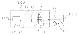
- FIG. 1 is a schematic diagram showing a configuration of a humidity sensor according to Embodiment 1;
- FIG. 1 is a schematic diagram showing a configuration of a humidity sensor according to Embodiment 1;
- FIG. 1 is a side cross-sectional view when an air conditioner 1 according to Embodiment 1 is installed in a room 2 of a building.
- the hollow arrows in FIG. 1 indicate the direction of the airflow.
- An air conditioner 1 according to Embodiment 1 is installed in a ceiling 3 portion of a room 2, and includes a suction port 4, a filter 5, a fan 6, a heat exchanger 7, a humidifying element 8, an air outlet 9, a humidity sensor 10, and a etc.
- the air conditioner 1 performs air conditioning on temperature, humidity, or the like for the air to be sent to the air destination of the room 2 .
- the air conditioner 1 is a package-type air conditioner that conditions the air in the room 2, and has a cooling function, a heating function, and a humidifying function.
- the package type air conditioner described here is only an example, and may be a cassette type air conditioner, a room air conditioner, an outside air processing unit, other air conditioners, or a blower device such as an electric fan having a blowing function.
- a room 2 is an indoor space of a building in which the air conditioner 1 is installed, such as a business office or a residence.
- An air conditioner 1 is fixed to a ceiling 3 of a room 2.
- the suction port 4 is an opening for taking in air from the room 2 into the air conditioner 1 by driving the fan 6, which will be described later.
- the suction port 4 functions as a suction port for sucking in the intake air to be conditioned by the air conditioner 1 in the suction direction.
- the suction port 4 is arranged so as to extend horizontally from the ceiling 3 toward the vertical direction.
- the filter 5 is a membrane filter for removing dust contained in the air sucked from the suction port 4 . As shown in FIG. 1, the filter 5 faces the suction port 4 in the vertical direction and is arranged to extend horizontally above the suction port 4 in the vertical direction.
- the fan 6 is a blowing means for blowing air from the air conditioner 1 into the interior of the room 2 toward a blowing destination located below the air conditioner 1 in the vertical direction.
- the fan 6 is arranged above the filter 5 in the vertical direction, as shown in FIG.
- the fan 6 has a rotating shaft extending vertically. When the air conditioner 1 blows air, the fan 6 is driven to rotate around the rotation axis and draws in air from vertically below. The sucked air is blown horizontally within the air conditioner 1 .
- the heat exchanger 7 is a device that heats or cools the air by exchanging heat with the air blown horizontally through the fan 6 .
- the heat exchanger 7 is, for example, a device having a fin-and-tube structure made of aluminum, and heat exchange between air passing around the heat exchanger 7 and refrigerant flowing inside the heat exchanger 7 The air is heated or cooled by The air blown through the fan 6 is heated or cooled by the heat exchanger 7, and then conveyed to the humidification element 8, which will be described later.
- the humidification element 8 is a device that humidifies the air that has been heated or cooled by the heat exchanger 7. As shown in FIG. 1, the humidifying element 8 is provided side by side so as to face the heat exchanger 7, and is configured in a filter shape using a porous or fibrous member such as paper or resin. . The humidifying element 8 is also configured, for example, so that the facing surface has the same length as the heat exchanger 7 . By adopting such a configuration having the same length, it is possible to suppress the pressure loss when the air that has passed through the heat exchanger 7 is subjected to humidity conditioning. The air humidified by the humidifying element 8 is blown out into the room 2 from an outlet 9, which will be described later.
- the air outlet 9 is an opening for supplying air humidified by the humidifying element 8 into the room 2 .
- the outlet 9 is arranged so as to extend horizontally from the ceiling 3 toward the vertical direction.
- the outlet 9 is arranged outside the outer periphery of the suction port 4 .
- the humidity sensor 10 transmits sound waves in a crossing direction that intersects the suction direction in which the air is drawn in by the suction port 4, and detects the humidity of the air sucked by the suction port 4.
- the humidity sensor 10 is a humidity detection device that measures the humidity of the air by irradiating sound waves in a direction that intersects the air blowing direction from the air outlet 9 to the air blowing destination.
- the humidity sensor 10 is arranged inside the air conditioner 1 . Specifically, the humidity sensor 10 is arranged between the suction port 4 and the filter 5 . By adopting such an arrangement, it becomes possible to suppress adhesion of dust to the humidity sensor 10 .
- the air conditioner 1 according to Embodiment 1 is an air conditioner in which a humidity sensor that transmits sound waves to the outside is arranged while enabling humidity measurement in the air using sound waves. It is possible to reduce the size by comparison.
- FIG. 2 is a schematic diagram showing the configuration of the humidity sensor 10 according to Embodiment 1.
- FIG. Humidity sensor 10 includes sensor unit 10A and reflective surface 10B.
- the humidity sensor 10 is horizontally spaced apart so that the air in the room 2 sucked into the air conditioner 1 from the suction port 4 flows between the sensor unit 10A and the reflecting surface 10B.
- the humidity of the air passing between the acoustic wave element 11 of the sensor unit 10A and the reflecting surface 10B follows the change in humidity of the air in the room 2 . Therefore, the humidity sensor 10 can measure the humidity of the air in the room 2 by measuring the humidity of the air passing between the acoustic wave element 11 of the sensor unit 10A and the reflecting surface 10B.
- the sensor unit 10A has a sound wave transmission function for transmitting sound waves.
- the sensor unit 10A according to an example of the first embodiment has an ultrasonic transmission function of transmitting ultrasonic waves, which are a type of sound waves and are difficult to hear with human ears. By using ultrasound, it is possible to avoid undue stimulation of the user's hearing.
- the sensor unit 10A is arranged so as to transmit ultrasonic waves in a cross direction crossing the suction direction of suction from the suction port 4 . Further, the sensor unit 10A is arranged so as to transmit ultrasonic waves in a direction intersecting with the blowing direction of the air blown out from the outlet 9 to the destination outside the air conditioner 1 by driving the fan 6 . In the example of FIG.
- the sensor unit 10A is arranged so as to transmit ultrasonic waves in a horizontal direction perpendicular to the blowing direction.
- the sensor unit 10A is arranged so that ultrasonic waves transmitted from the sensor unit 10A are reflected by the reflecting surface 10B.
- the air conditioner 1 according to Embodiment 1 can measure the humidity in the air using sound waves, while compared with an air conditioner in which a humidity sensor that transmits sound waves to the outside is arranged. miniaturization becomes possible.
- the reflecting surface 10B is a member that reflects the ultrasonic waves transmitted from the sensor unit 10A.
- the reflecting surface 10B is arranged so as to deliver the reflected ultrasonic waves to the sensor unit 10A.
- the reflecting surface 10B is arranged at a position separated from the sensor unit 10A in the horizontal direction perpendicular to the suction direction.
- the reflecting surface 10B is also arranged at a position separated from the sensor unit 10A in the horizontal direction orthogonal to the blowing direction.
- the humidity sensor 10 extends in the horizontal direction instead of the suction direction or the air blowing direction, so the air conditioner 1 according to Embodiment 1 can measure the humidity in the air using sound waves.
- the sensor unit 10A includes an acoustic wave element 11, electric wires 12, 13, 18, a control section 14, a drive section 15, a detection section 16, a calculation section 17, and wind speed management means 19.
- the acoustic wave element 11 is an element that transmits and receives sound waves, and in one example of this embodiment, is an element that transmits and receives ultrasonic waves, and includes a sound wave transmission/reception surface that transmits and receives sound waves.
- a sound wave transmitting/receiving surface of the sound wave element 11 is arranged to be connected to the air conditioner 1 so as to face the reflecting surface 10B.
- the sound wave transmitting/receiving surface of the sound wave element 11 is preferably connected to the air conditioner 1 so as to face the reflecting surface 10B in the horizontal direction perpendicular to the suction direction.
- the air conditioner 1 can be further miniaturized.
- the sound wave element 11 has a sound wave transmission function for transmitting sound waves, and transmits, for example, sound waves with a frequency of 20 kHz or higher, and ultrasonic waves in one example in this embodiment.
- the acoustic wave element 11 has a mechanism that emits ultrasonic waves by applying a voltage to piezoelectric ceramics. Piezoelectric ceramics can not only transmit ultrasonic waves, but also receive ultrasonic waves propagating in the air and convert them into voltage. That is, the acoustic wave element 11 has a function capable of transmitting and receiving ultrasonic waves.
- the reflecting surface 10B is a reflecting member that reflects the sound wave transmitted by the sound wave element 11.
- the smooth surface of the wall surface of the air conditioner 1 may be sufficient, and the board
- the reflecting surface 10B may be made of, for example, a resin that is used as a member of the air conditioner 1, or may be made of metal.
- the space between the sound wave transmitting/receiving surface of the sound wave element 11 and the reflecting surface 10B functions as a measurement unit that measures sound waves.
- the acoustic wave element 11 and the reflecting surface 10B are connected to the air conditioner 1 at a predetermined arbitrary distance.
- the reflecting surface 10B should be arranged so as to face the acoustic wave element 11 at least so as to reflect the acoustic wave transmitted from the acoustic wave element 11 and maintain a relationship in which the reflected acoustic wave can be received by the acoustic wave element 11. .
- the air conditioner 1 is configured to allow the sucked air of the room 2 to flow between the sensor unit 10A and the reflecting surface 10B of the humidity sensor 10 .
- the air conditioner 1 measures the humidity of the air to be blown by the blowing means such as the fan 6 before air conditioning.
- the air conditioner 1 has a configuration in which a sound wave reflecting surface is provided at the air blowing destination in order to propagate sound waves between the air blowing source and the air blowing destination, and air blowing means such as the fan 6 It is possible to realize miniaturization while making it possible to measure the humidity of the air to be blown before air conditioning.
- the control unit 14 is a control device that controls driving of the acoustic wave element 11 .
- the control unit 14 is electrically connected to the acoustic wave element 11 via electric wires 12 and 13 .
- the control unit 14 includes a drive unit 15, a detection unit 16, a calculation unit 17, and the like.
- a drive section 15 of the control section 14 is electrically connected to the acoustic wave element 11 via the electric wire 12 .
- the drive unit 15 is a drive device that drives the acoustic wave element 11 by applying a pulse wave to the acoustic wave element 11 .
- the drive unit 15 applies a pulse wave to the acoustic wave element 11, the acoustic wave element 11 transmits an ultrasonic wave as the transmission wave 20 based on the applied pulse wave.
- the detection section 16 of the control section 14 is electrically connected to the acoustic wave element 11 via the electric wire 13 .
- the acoustic wave element 11 receives, as a received wave 21, the transmitted wave 20 reflected by the reflecting surface 10B.
- the acoustic wave element 11 converts the vibration of the received ultrasonic wave into a voltage and outputs the voltage to the detection unit 16 as an analog signal.
- the detection unit 16 has an AD conversion function for converting an analog signal into a digital signal, and acquires a digital signal by AD converting the output from the acoustic wave element 11 into a digital signal.
- the sampling frequency of the detector 16 is 2.4 MHz and the resolution is 12 bits.
- the detection unit 16 may include, for example, means for amplifying the analog signal output from the acoustic wave element 11 . By amplifying the analog signal, the difference from the mixed noise is increased, the SN ratio is improved, and the measurement accuracy can be improved.
- the calculation unit 17 analyzes the waveform of the digital signal acquired by the detection unit 16 to detect humidity.
- the control unit 14 is also electrically connected to the wind speed management means 19 via the electric wire 18 .
- the wind speed management means 19 controls the rotation of the fan 6 of the air conditioner 1 based on the operating state of the air conditioner 1, for example, the rotation speed of the fan 6 input to the control unit 14, or based on a command from the control unit 14. Manage numbers.
- the control unit 14 outputs the humidity value measured by the humidity sensor 10 to the air conditioner 1, and performs the humidification operation of the air conditioner 1 so that the measured humidity value and the set value of the humidity of the air conditioner 1 match. Control the execution.
- the control unit 14 is composed of dedicated hardware or a processing circuit using a processor. Therefore, each function of the drive unit 15 and the detection unit 16 of the control unit 14 is realized in software by the processing circuit.
- the dedicated hardware may be, for example, ASIC (Application Specific Integrated Circuit) or FPGA (Field Programmable Gate Array).
- a processor may be a device that executes a program stored in memory.
- the calculation unit 17 of the control unit 14 has a storage unit such as a memory.
- the storage unit may be non-volatile or volatile semiconductor memory such as RAM (Random Access Memory), ROM (Read Only Memory), flash memory, EPROM (Erasable Programmable ROM), magnetic disk, flexible disk, optical disk It may be a disk such as
- the distance between the ultrasonic transmission/reception surface of the acoustic wave element 11 and the reflection surface 10B can be arbitrarily set. However, if the distance between the ultrasonic wave transmitting/receiving surface of the acoustic wave element 11 and the reflecting surface 10B is too long, the ultrasonic waves may be attenuated and may not reach the reflecting surface 10B. Ultrasonic waves with lower frequencies can travel farther than those with higher frequencies. However, ultrasound has greater directivity at lower frequencies than at higher frequencies. When the directivity of ultrasonic waves is large, irregular reflection occurs more easily than when the directivity is small. If irregular reflection occurs, the waveform may become complicated when detected by the acoustic wave element 11 . Therefore, the occurrence of irregular reflection is not preferable.
- the suction port 4 is about 1 to 2 m at the maximum
- the frequency at which the ultrasonic wave reaches a point several meters away should be considered.
- An example in which 40 kHz is used as the frequency of ultrasonic waves will be described below.
- the control unit 14 applies a pulse wave with a frequency of 40 kHz to the acoustic wave element 11 to generate ultrasonic waves.
- the method of transmitting ultrasonic waves is not limited to pulse waves, and may be continuous waves such as alternating current.
- the acoustic wave element 11 transmits an ultrasonic wave as the transmission wave 20 toward the reflecting surface 10B. Also, the acoustic wave element 11 receives the ultrasonic wave reflected by the reflecting surface 10B as the received wave 21 .
- the acoustic wave element 11 When received as the received wave 21 , the acoustic wave element 11 converts the vibration of the ultrasonic wave received as the received wave 21 into a voltage and outputs the voltage to the detection unit 16 .
- the output of the acoustic wave element 11 that is converted into voltage and output is referred to as voltage output.
- the acoustic wave element 11 is configured to receive an ultrasonic wave containing at least one of a component derived from the transmitted wave 20 transmitted by the acoustic wave element 11 and a component derived from the received wave 21 reflected by the reflecting surface 10B. I have
- the acoustic wave element 11 is configured to transmit a voltage output to the detection section 16 via the electric wire 13 .
- the detection unit 16 converts the voltage output transmitted from the acoustic wave element 11 into a digital signal by AD-converting the voltage output transmitted from the acoustic wave element 11 .
- the detection unit 16 outputs the converted digital signal to the calculation unit 17 .
- the calculation unit 17 calculates and outputs humidity based on the voltage output from the detection unit 16 .
- the humidity output by the calculation unit 17 indicates the humidity of the air in the room 2 sucked into the air conditioner 1 detected by the humidity sensor 10 .
- the air conditioner 1 calculates the propagation time of the ultrasonic wave until the ultrasonic wave element 11 receives the ultrasonic wave transmitted by the ultrasonic wave element 11. Measurement is performed by the control unit 14 .
- the acoustic wave element 11 acquires the voltage change of the ultrasonic wave transmitted by the acoustic wave element 11 until the ultrasonic wave element 11 receives the ultrasonic wave.
- a temperature measuring means (not shown) measures the temperature of the air through which the ultrasonic wave transmitted by the ultrasonic wave element 11 propagates when the ultrasonic wave element 11 receives the ultrasonic wave.
- the calculation unit 17 stores a preset distance between the sound wave transmitting/receiving surface of the sound wave element 11 and the reflecting surface 10B.
- the air conditioner 1 according to Embodiment 1 calculates the humidity by the calculation unit 17 based on a combination of information such as a change in the voltage waveform of the sound wave, the propagation time of the sound wave, the temperature, the propagation distance of the sound wave, and the like. demand.
- the air conditioner 1 performs air humidity control based on the humidity obtained by the calculation unit 17 .
- the air conditioner 1 according to Embodiment 1 transmits and receives ultrasonic waves in a direction that intersects the blowing direction of the air that is blown out from the air outlet 9 to the blowing destination outside the air conditioner 1. configured. Therefore, compared with an air conditioner equipped with a conventional sonic humidity measurement device that propagates sound waves between the air conditioner that is the air blow source and the air blow destination, the humidity in the air is measured using sound waves. Further miniaturization is possible while making it possible. Further, the air conditioner 1 according to Embodiment 1 can transmit ultrasonic waves in a direction intersecting with the blowing direction of the air blown from the blower outlet 9 to a blowing destination outside the air conditioner 1. The distance between the element 11 and the reflecting surface 10B is fixed.
- the air conditioner 1 since the air conditioner 1 according to Embodiment 1 transmits ultrasonic waves in a direction that intersects the blowing direction of the air blown from the blower outlet 9 to the blowing destination outside the air conditioner 1, it becomes a blowing source. Compared to conventional sonic wave humidity measurement equipment that propagates sound waves between the air conditioner and the air blowing destination outside the air conditioner, it reduces the influence of the external environment on the transmitted ultrasonic waves and improves the humidity measurement accuracy. improvement is possible.
- the air conditioner 1 controls the humidity of the room by dehumidifying/humidifying the air drawn into the air conditioner 1 based on the humidity measurement result.
- a method for manufacturing the air conditioner 1 according to Embodiment 1 will be described.
- a suction port arranging step is performed for arranging the suction port 4 for sucking in the suction direction of the suction air to be conditioned by the air conditioner 1, and the humidity of the suction air sucked by the suction port 4 is measured.
- a humidity sensor arranging step of arranging the humidity sensor 10 to be detected is executed.
- the humidity sensor 10 is configured to detect humidity by transmitting and receiving ultrasonic waves in a cross direction crossing the suction direction. Therefore, compared with an air conditioner equipped with a conventional sonic humidity measurement device that propagates sound waves between the air conditioner that is the air blow source and the air blow destination, the humidity in the air is measured using sound waves. Further miniaturization is possible while making it possible.
- a sonic element arranging step of arranging the sonic element 11 for transmitting and receiving ultrasonic waves as the humidity sensor 10 is further performed, and a reflective surface for reflecting the ultrasonic wave transmitted by the sonic element 11 to the sonic element is formed.
- 10B is arranged.
- the reflecting surface 10B is arranged apart from the acoustic wave element 11 in the crossing direction.
- an air outlet arranging step for arranging the air outlet 9 for blowing out the sucked air whose humidity is detected by the humidity sensor 10 toward the blowing destination in the air blowing direction is further executed. placed so that it intersects with A configuration in which the suction direction and the crossing direction are orthogonal is preferable.
- the air conditioner 1 is an air conditioner equipped with a conventional sonic humidity measuring device that propagates sound waves between the air conditioner serving as the air blowing source and the air blowing destination. Compared to conventional instruments, it is possible to measure the humidity in the air using sound waves, and at the same time, it is possible to make it even more compact.
- the acoustic wave element 11 may emit an audible sound wave with a frequency of 20 kHz or less.
- the frequencies and wavelengths are different for ultrasound, the phenomena that occur are similar. Therefore, the same effects as in the case of ultrasonic waves can be obtained.
- Embodiment 1 an example in which the wind speed management means 19 is provided has been described, but the present invention is not limited to this example.
- a configuration in which the operating state of the air conditioner 1 is directly input to the humidity sensor 10 without providing the wind speed control means 19 may be employed. This modification can improve the degree of freedom in designing the air conditioner 1 .
- Embodiment 1 an example of a configuration in which the sensor unit 10A that transmits and receives ultrasonic waves and the reflecting surface 10B that reflects the transmitted ultrasonic waves are separated from each other is provided in the humidity sensor 10 has been described.
- the invention is not limited to this example.
- the humidity sensor 10 may be configured such that a transmitting sensor unit that transmits ultrasonic waves and a receiving sensor unit that receives ultrasonic waves are separated from each other. With this configuration, the degree of freedom in designing the humidity sensor of the air conditioner can be improved.
Landscapes
- Engineering & Computer Science (AREA)
- Chemical & Material Sciences (AREA)
- Combustion & Propulsion (AREA)
- Mechanical Engineering (AREA)
- General Engineering & Computer Science (AREA)
- Air Conditioning Control Device (AREA)
- Investigating Or Analyzing Materials By The Use Of Ultrasonic Waves (AREA)
Priority Applications (2)
| Application Number | Priority Date | Filing Date | Title |
|---|---|---|---|
| PCT/JP2021/026474 WO2023286207A1 (ja) | 2021-07-14 | 2021-07-14 | 空気調和機および空気調和機の製造方法 |
| JP2022503562A JP7317204B2 (ja) | 2021-07-14 | 2021-07-14 | 空気調和機および空気調和機の製造方法 |
Applications Claiming Priority (1)
| Application Number | Priority Date | Filing Date | Title |
|---|---|---|---|
| PCT/JP2021/026474 WO2023286207A1 (ja) | 2021-07-14 | 2021-07-14 | 空気調和機および空気調和機の製造方法 |
Publications (1)
| Publication Number | Publication Date |
|---|---|
| WO2023286207A1 true WO2023286207A1 (ja) | 2023-01-19 |
Family
ID=84919166
Family Applications (1)
| Application Number | Title | Priority Date | Filing Date |
|---|---|---|---|
| PCT/JP2021/026474 Ceased WO2023286207A1 (ja) | 2021-07-14 | 2021-07-14 | 空気調和機および空気調和機の製造方法 |
Country Status (2)
| Country | Link |
|---|---|
| JP (1) | JP7317204B2 (cg-RX-API-DMAC7.html) |
| WO (1) | WO2023286207A1 (cg-RX-API-DMAC7.html) |
Citations (3)
| Publication number | Priority date | Publication date | Assignee | Title |
|---|---|---|---|---|
| JPH0894594A (ja) * | 1994-09-28 | 1996-04-12 | Matsushita Electric Works Ltd | 超音波湿度センサ及び超音波温湿度センサ |
| JP2003194388A (ja) * | 2001-12-28 | 2003-07-09 | Daikin Ind Ltd | 空気調和機 |
| JP2012225756A (ja) * | 2011-04-19 | 2012-11-15 | Panasonic Corp | 湿度計測装置 |
Family Cites Families (4)
| Publication number | Priority date | Publication date | Assignee | Title |
|---|---|---|---|---|
| EP1632763A1 (de) * | 2004-09-03 | 2006-03-08 | Siemens Schweiz AG | Vorrichtung zur Erfassung von Raumklimagrössen |
| US8519854B2 (en) * | 2007-10-26 | 2013-08-27 | Panasonic Corporation | Fire alarm system |
| WO2021176545A1 (ja) * | 2020-03-03 | 2021-09-10 | 三菱電機株式会社 | 湿度センサ |
| US11796509B2 (en) * | 2020-05-07 | 2023-10-24 | Mitsubishi Electric Corporation | Humidity sensor and air-conditioning apparatus |
-
2021
- 2021-07-14 WO PCT/JP2021/026474 patent/WO2023286207A1/ja not_active Ceased
- 2021-07-14 JP JP2022503562A patent/JP7317204B2/ja active Active
Patent Citations (3)
| Publication number | Priority date | Publication date | Assignee | Title |
|---|---|---|---|---|
| JPH0894594A (ja) * | 1994-09-28 | 1996-04-12 | Matsushita Electric Works Ltd | 超音波湿度センサ及び超音波温湿度センサ |
| JP2003194388A (ja) * | 2001-12-28 | 2003-07-09 | Daikin Ind Ltd | 空気調和機 |
| JP2012225756A (ja) * | 2011-04-19 | 2012-11-15 | Panasonic Corp | 湿度計測装置 |
Also Published As
| Publication number | Publication date |
|---|---|
| JPWO2023286207A1 (cg-RX-API-DMAC7.html) | 2023-01-19 |
| JP7317204B2 (ja) | 2023-07-28 |
Similar Documents
| Publication | Publication Date | Title |
|---|---|---|
| ES2953305T3 (es) | Unidad exterior de un aparato de acondicionamiento de aire equipada con sistema de control de ruido | |
| JP4547029B2 (ja) | 空気調和機 | |
| US11994532B2 (en) | Ultrasonic anemometers systems for sensing air flows in rooms and ducts | |
| CN102243869A (zh) | 用于空气处理单元中的有源声衰减的方法和系统 | |
| JP6927449B1 (ja) | 環境検出システム | |
| JP7317204B2 (ja) | 空気調和機および空気調和機の製造方法 | |
| JP2840564B2 (ja) | 横断流送風機の騒音減少装置 | |
| JP2004226050A (ja) | 空調機器 | |
| US20140133667A1 (en) | System and method for attenuating noise from a fluid machine or a turbulent noise source | |
| CN112119264B (zh) | 空气调节器 | |
| JP6843309B1 (ja) | 湿度センサおよび空気調和機 | |
| EP4230873A1 (en) | Noise reduced blower means and their use in electric power tools and devices | |
| JP2010270999A (ja) | 空気調和機 | |
| JP6746048B1 (ja) | 湿度センサ | |
| JP2022070575A (ja) | 音制御装置 | |
| JPWO2021038613A5 (cg-RX-API-DMAC7.html) | ||
| JP3829349B2 (ja) | クロスフローファン | |
| JP2010185592A (ja) | 空気調和機 | |
| JP6419999B1 (ja) | 吸気装置 | |
| JP4553867B2 (ja) | 超音波センサ並びに設備機器 | |
| JPH0560357A (ja) | 室内温度制御装置 | |
| JP2022029658A (ja) | 送風機及び、空調機の室内ユニット | |
| Fridman et al. | A generic silent blower module based on a dual active noise control system | |
| JP2022042576A (ja) | シロッコファンおよび空調機器 | |
| JP2023113127A (ja) | ガス検出機能付き機器 |
Legal Events
| Date | Code | Title | Description |
|---|---|---|---|
| ENP | Entry into the national phase |
Ref document number: 2022503562 Country of ref document: JP Kind code of ref document: A |
|
| 121 | Ep: the epo has been informed by wipo that ep was designated in this application |
Ref document number: 21950148 Country of ref document: EP Kind code of ref document: A1 |
|
| NENP | Non-entry into the national phase |
Ref country code: DE |
|
| 122 | Ep: pct application non-entry in european phase |
Ref document number: 21950148 Country of ref document: EP Kind code of ref document: A1 |