WO2023286191A1 - 情報処理装置および駆動データ生成方法 - Google Patents
情報処理装置および駆動データ生成方法 Download PDFInfo
- Publication number
- WO2023286191A1 WO2023286191A1 PCT/JP2021/026415 JP2021026415W WO2023286191A1 WO 2023286191 A1 WO2023286191 A1 WO 2023286191A1 JP 2021026415 W JP2021026415 W JP 2021026415W WO 2023286191 A1 WO2023286191 A1 WO 2023286191A1
- Authority
- WO
- WIPO (PCT)
- Prior art keywords
- unit
- user
- virtual
- presentation unit
- movement
- Prior art date
- Legal status (The legal status is an assumption and is not a legal conclusion. Google has not performed a legal analysis and makes no representation as to the accuracy of the status listed.)
- Ceased
Links
Images






Classifications
-
- A—HUMAN NECESSITIES
- A63—SPORTS; GAMES; AMUSEMENTS
- A63F—CARD, BOARD, OR ROULETTE GAMES; INDOOR GAMES USING SMALL MOVING PLAYING BODIES; VIDEO GAMES; GAMES NOT OTHERWISE PROVIDED FOR
- A63F13/00—Video games, i.e. games using an electronically generated display having two or more dimensions
- A63F13/25—Output arrangements for video game devices
- A63F13/28—Output arrangements for video game devices responding to control signals received from the game device for affecting ambient conditions, e.g. for vibrating players' seats, activating scent dispensers or affecting temperature or light
- A63F13/285—Generating tactile feedback signals via the game input device, e.g. force feedback
-
- A—HUMAN NECESSITIES
- A63—SPORTS; GAMES; AMUSEMENTS
- A63F—CARD, BOARD, OR ROULETTE GAMES; INDOOR GAMES USING SMALL MOVING PLAYING BODIES; VIDEO GAMES; GAMES NOT OTHERWISE PROVIDED FOR
- A63F13/00—Video games, i.e. games using an electronically generated display having two or more dimensions
- A63F13/20—Input arrangements for video game devices
- A63F13/21—Input arrangements for video game devices characterised by their sensors, purposes or types
- A63F13/211—Input arrangements for video game devices characterised by their sensors, purposes or types using inertial sensors, e.g. accelerometers or gyroscopes
-
- A—HUMAN NECESSITIES
- A63—SPORTS; GAMES; AMUSEMENTS
- A63F—CARD, BOARD, OR ROULETTE GAMES; INDOOR GAMES USING SMALL MOVING PLAYING BODIES; VIDEO GAMES; GAMES NOT OTHERWISE PROVIDED FOR
- A63F13/00—Video games, i.e. games using an electronically generated display having two or more dimensions
- A63F13/20—Input arrangements for video game devices
- A63F13/23—Input arrangements for video game devices for interfacing with the game device, e.g. specific interfaces between game controller and console
- A63F13/235—Input arrangements for video game devices for interfacing with the game device, e.g. specific interfaces between game controller and console using a wireless connection, e.g. infrared or piconet
-
- A—HUMAN NECESSITIES
- A63—SPORTS; GAMES; AMUSEMENTS
- A63F—CARD, BOARD, OR ROULETTE GAMES; INDOOR GAMES USING SMALL MOVING PLAYING BODIES; VIDEO GAMES; GAMES NOT OTHERWISE PROVIDED FOR
- A63F13/00—Video games, i.e. games using an electronically generated display having two or more dimensions
- A63F13/20—Input arrangements for video game devices
- A63F13/24—Constructional details thereof, e.g. game controllers with detachable joystick handles
-
- A—HUMAN NECESSITIES
- A63—SPORTS; GAMES; AMUSEMENTS
- A63F—CARD, BOARD, OR ROULETTE GAMES; INDOOR GAMES USING SMALL MOVING PLAYING BODIES; VIDEO GAMES; GAMES NOT OTHERWISE PROVIDED FOR
- A63F13/00—Video games, i.e. games using an electronically generated display having two or more dimensions
- A63F13/55—Controlling game characters or game objects based on the game progress
-
- G—PHYSICS
- G06—COMPUTING OR CALCULATING; COUNTING
- G06F—ELECTRIC DIGITAL DATA PROCESSING
- G06F3/00—Input arrangements for transferring data to be processed into a form capable of being handled by the computer; Output arrangements for transferring data from processing unit to output unit, e.g. interface arrangements
- G06F3/01—Input arrangements or combined input and output arrangements for interaction between user and computer
-
- G—PHYSICS
- G06—COMPUTING OR CALCULATING; COUNTING
- G06T—IMAGE DATA PROCESSING OR GENERATION, IN GENERAL
- G06T19/00—Manipulating three-dimensional [3D] models or images for computer graphics
- G06T19/20—Editing of three-dimensional [3D] images, e.g. changing shapes or colours, aligning objects or positioning parts
-
- G—PHYSICS
- G06—COMPUTING OR CALCULATING; COUNTING
- G06T—IMAGE DATA PROCESSING OR GENERATION, IN GENERAL
- G06T2219/00—Indexing scheme for manipulating 3D models or images for computer graphics
- G06T2219/20—Indexing scheme for editing of 3D models
- G06T2219/2004—Aligning objects, relative positioning of parts
Definitions
- the present invention relates to technology for providing haptic feedback and/or haptic feedback to a user.
- Patent Document 1 discloses a portable computer interface comprising a housing, a mass coupled to the housing, and an actuator coupled to the mass for changing the position of the mass relative to the housing.
- the portable computer interface disclosed in US Pat. No. 5,800,005 is used as a game controller, providing feedback to the user by moving masses.
- a Head Mounted Display (HMD) is worn on the user's head and provides the user with a virtual reality (VR) visual world. Recently, it has become common to connect an HMD to a game device and play a game by operating an operating device while viewing a game image displayed on the HMD.
- VR virtual reality
- the user While playing the game, the user can experience the results of game operations realistically by being given feedback from the game through the operation device. Therefore, by effectively providing haptic feedback and/or haptic feedback to the user, it is believed that the entertainment of applications such as games can be improved.
- the present invention has been made in view of this situation, and its purpose is to realize a technology that provides haptic feedback and/or haptic feedback to the user.
- an information processing apparatus includes an operation information acquisition unit that acquires operation information indicating a movement of an operation device held by a user; and a control unit that controls the movement of a virtual device corresponding to an operation device according to operation information, wherein the operation device is a haptic presentation unit that presents a haptic to a user's hand. and a tactile sense presenting unit that presents a tactile sense to the user's hand, and the control unit provides first drive data and a tactile sense for driving the haptic sense presenting unit based on the relationship between the virtual device and the virtual object. Generate second drive data for driving the presentation unit.
- a drive data generation method comprising: acquiring operation information indicating movement of an operation device held by a user; according to the operation information; and first drive data for driving a haptic presentation unit that presents a haptic to the user's hand based on the relationship between the virtual device and the virtual object, and the user's and generating second drive data for driving a tactile sense presentation unit that presents a tactile sense to a hand.
- FIG. 3 is a diagram showing an example of an image displayed on a display panel;
- FIG. 10 is a diagram showing the entry of the virtual device into the ink;
- FIG. 3 is a diagram showing an example of an image displayed on a display panel;
- FIG. 10 is a diagram showing an example of a map that defines the relationship between the approach length and the amount of movement of the movable portion; It is a figure which shows the example of a vibration waveform.
- FIG. 10 is a diagram showing an example of a map that defines the relationship between the moving speed and the amount of vibration of the vibrating portion;
- FIG. 3 is a diagram showing an example of an image displayed on a display panel;
- FIG. 3 is a diagram showing an example of an image displayed on a display panel;
- FIG. FIG. 10 is a diagram showing an example of a map that defines the relationship between the elapsed time from a collision and the amount of movement of a movable part; It is a figure which shows the example of a vibration waveform.
- FIG. 1 shows a configuration example of an information processing system 1 in an embodiment.
- the information processing system 1 includes an information processing device 10, a recording device 11, a head mounted display (HMD) 100 worn on the user's head, an operation device 20 held by the user's hand, and the HMD 100 and the operation device 20. and an output device 15 for outputting images and sounds.
- Output device 15 may be a television.
- the information processing device 10 is connected to an external network 2 such as the Internet via an access point (AP) 17 .
- the AP 17 has the functions of a wireless access point and router, and the information processing device 10 may be connected to the AP 17 by a cable or by a known wireless communication protocol.
- the recording device 11 records applications such as system software and game software.
- the information processing device 10 may download the application from the content server to the recording device 11 via the network 2 .
- the information processing device 10 executes an application and supplies image data and sound data of the application to the HMD 100 and the output device 15 .
- the information processing device 10 and the HMD 100 may be connected by a known wireless communication protocol, or may be connected by a cable.
- the HMD 100 is a display device that displays an image on a display panel positioned in front of the user's eyes when worn by the user.
- the HMD 100 separately displays a left-eye image on the left-eye display panel and a right-eye image on the right-eye display panel. These images constitute parallax images viewed from left and right viewpoints, and achieve stereoscopic vision. Since the user views the display panel through an optical lens, the information processing apparatus 10 supplies the HMD 100 with parallax image data corrected for optical distortion caused by the lens.
- the HMD 100 provides the user with a virtual reality (VR) visual world.
- VR virtual reality
- a user wearing the HMD 100 does not need the output device 15, but by preparing the output device 15, another user can view the display image of the output device 15.
- the information processing apparatus 10 may cause the output device 15 to display the same image as the image viewed by the user wearing the HMD 100, or may cause the output device 15 to display a different image. For example, when a user wearing an HMD and another user play a game together, the output device 15 may display a game image from the viewpoint of the character of the other user.
- the operation device 20 is a controller that is driven by a battery and has one or more operation buttons for inputting operations for applications.
- the operation input is transmitted to the information processing device 10 by wireless communication.
- a wireless connection may be established between the controller device 20 and the information processing device 10 using, for example, the Bluetooth (registered trademark) protocol.
- the information processing device 10 receives an operation input from the operation device 20 , controls the progress of the application according to the operation input, generates image data and sound data of the application, and supplies the generated image data and sound data to the HMD 100 and the output device 15 .
- the operation device 20 is not limited to a wireless controller, and may be a wired controller connected to the information processing device 10 via a cable.
- the operation device 20 includes a posture sensor including a 3-axis acceleration sensor and a 3-axis gyro sensor, and transmits sensor data to the information processing device 10 at predetermined intervals.
- the drawing application of the embodiment moves the virtual device 22 corresponding to the operating device 20 within the virtual three-dimensional space in accordance with the movement of the operating device 20 held by the user's hand. Therefore, information processing apparatus 10 derives the position, orientation, and/or movement of operation device 20 based on sensor data transmitted from operation device 20, and calculates the derived position, orientation, and/or movement of operation device 20. , as operation information for moving the virtual device 22 .
- the imaging device 14 is a video camera configured with a CCD imaging element, a CMOS imaging element, or the like, and photographs the real space at a predetermined cycle to generate a frame image for each cycle. It is preferable that the imaging device 14 is a stereo camera and the information processing device 10 can measure the distance to the object from the captured image. The imaging speed of the imaging device 14 may be set to 60 frames/second to match the frame rate of the HMD 100 .
- the imaging device 14 is connected to the information processing device 10 via USB (Universal Serial Bus) or other interfaces.
- the HMD 100 is provided with a marker (tracking LED) for tracking the user's head, and the information processing device 10 detects the movement of the HMD 100 based on the position of the marker included in the captured image.
- the HMD 100 is equipped with an orientation sensor (three-axis acceleration sensor and three-axis gyro sensor).
- highly accurate tracking processing may be performed to detect the position and orientation of the user's head (actually HMD 100) in real space.
- the position of the HMD 100 is the position coordinates in a three-dimensional space with the reference position as the origin, and the reference position may be the position coordinates (latitude, longitude) when the power of the HMD 100 is turned on.
- the posture of the HMD 100 is the inclination in the three-axis directions with respect to the reference posture in the three-dimensional space. Attitude may be set.
- Various methods have been conventionally proposed for tracking processing, and any tracking method may be employed as long as the information processing apparatus 10 can detect the movement of the HMD 100 .
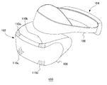
- FIG. 2 shows an example of the external shape of the HMD 100.
- the HMD 100 is composed of an output mechanism section 102 and a mounting mechanism section 104 .
- the mounting mechanism unit 104 includes a mounting band 106 that is worn by the user and wraps around the head to fix the HMD 100 to the head.
- the mounting band 106 has a material or structure whose length can be adjusted according to the circumference of the user's head.
- the output mechanism unit 102 includes a housing 108 shaped to cover the left and right eyes when the user wears the HMD 100, and has a display panel inside that faces the eyes when the HMD 100 is worn.
- the display panel may be a liquid crystal panel, an organic EL panel, or the like.
- the housing 108 further includes a pair of left and right optical lenses positioned between the display panel and the user's eyes to expand the viewing angle of the user.
- the HMD 100 may further include speakers and earphones at positions corresponding to the ears of the user, and may be configured to connect external headphones.
- a plurality of luminous markers 110a, 110b, 110c, and 110d are provided on the outer surface of the housing 108.
- the tracking LED constitutes the light-emitting marker 110, but it may be another type of marker. I wish I had.
- the number and arrangement of the light-emitting markers 110 are not particularly limited, but the number and arrangement must be such that the orientation of the HMD 100 can be detected.
- the luminous marker 110 may be provided on the side or rear portion of the wearing band 106 so that the user can take an image even when the back of the imaging device 14 is turned.
- FIG. 3 shows the functional blocks of the HMD 100.
- the control unit 120 is a main processor that processes and outputs various data such as image data, sound data, sensor data, and commands.
- Storage unit 122 temporarily stores data, instructions, and the like processed by control unit 120 .
- the orientation sensor 124 detects orientation information of the HMD 100 .
- the attitude sensor 124 includes at least a triaxial acceleration sensor and a triaxial gyro sensor.
- the communication control unit 128 transmits data output from the control unit 120 to the external information processing device 10 by wired or wireless communication via a network adapter or an antenna. Further, the communication control unit 128 receives data from the information processing device 10 by wired or wireless communication via a network adapter or an antenna, and outputs the data to the control unit 120 .
- the control unit 120 Upon receiving image data and sound data from the information processing apparatus 10, the control unit 120 supplies the data to the display panel 130 for display, and supplies the data to the sound output unit 132 for output.
- the display panel 130 includes a left-eye display panel 130a and a right-eye display panel 130b, and each display panel displays a pair of parallax images.
- the control unit 120 also causes the communication control unit 128 to transmit sensor data from the posture sensor 124 and audio data from the microphone 126 to the information processing apparatus 10 .
- FIG. 4 shows a state in which the user holds the operating device 20 of the embodiment.
- 4(a) shows the operating device 20 viewed from the front
- FIG. 4(b) shows the operating device 20 viewed from the side.
- the operating device 20 includes a base 30 that is held by a user's hand, and a movable portion 32 that is relatively movable with respect to the base 30 .
- the movable section 32 functions as a haptic presentation section that presents a haptic sensation to the user's hand, and is driven based on drive data transmitted from the information processing device 10 to provide haptic feedback to the user.
- the operating device 20 is a pen-shaped haptic device, and the substrate 30 has two side surfaces arranged substantially parallel. The user uses the operating device 20 with both sides of the base 30 held between the thumb and middle finger and the index finger placed on the movable portion 32 .
- FIG. 5 is a side view of the operating device 20.
- the side on which the movable portion 32 is provided is defined as the front end side, and the left side is called the front side and the right side is called the rear side in the side view shown in FIG.
- the movable portion 32 is at a position protruding forward most from the base 30, and this position is the "reference position" of the movable portion 32. As shown in FIG.
- a finger rest part 36 is provided on the upper surface of the movable part 32 for the user to place the tip of the index finger while gripping the base body 30 .
- a finger engaging portion 34 with which the tip of the finger is engaged is provided at the front end of the finger rest portion 36 .
- the finger engaging portion 34 is erected in a direction different from the direction of movement of the movable portion 32 (that is, the front-rear direction). ing.
- the finger engaging portion 34 has a curved surface 34a that is inclined along the pad of the finger and has a curvature.
- the curved surface 34a is inclined with respect to the upper surface of the movable part 32 and is concave in the direction in which the fingertip is brought into contact, the user can stably bring the tip of the index finger into contact with the curved surface 34a. can.
- a vibrating section 40 including a vibrator is provided in a portion on the tip side of the base 30, specifically, a portion where the thumb or middle finger is placed.
- the vibrating section 40 may be provided on both sides of the tip of the base 30 .
- the vibration unit 40 functions as a tactile sense presenting unit that presents a tactile sense to the user's hand, and is driven based on drive data transmitted from the information processing device 10 to provide tactile feedback to the user.
- the finger rest part 36 is provided with an operation button 42 that can be operated with the tip of the index finger.
- the operation button 42 is a push button, and the user pushes the operation button 42 to turn on a switch (not shown) having a contact structure.
- the operation button 42 is provided on the finger rest portion 36 on the rear side of the curved surface 34a. By providing the operation button 42 on the finger rest portion 36, the user can freely operate the operation button 42 with the index finger while holding the base 30 between the thumb and the middle finger.
- FIG. 6(a) shows a state in which the finger is placed on the movable portion 32 at the reference position.
- the tip portion of the finger fits and contacts the curved surface 34a. Since the tip portion of the finger contacts the finger engaging portion 34 in this manner, the finger reliably moves together with the finger engaging portion 34 when the movable portion 32 moves in the direction in which the movable portion 32 is pulled into the base 30 .
- FIG. 6(b) shows a state in which the movable part 32 moves in the direction in which it is drawn into the base 30.
- the finger tip part moves in conjunction with the movable part 32 due to the frictional force acting between it and the finger rest part 36 .
- the tip of the finger is in contact with the finger engaging portion 34 erected in the direction perpendicular to the moving direction, so that the movement of the movable portion 32 is reliably interlocked.
- the control unit 50 is a main processor that processes and outputs various data such as sensor data and drive data, and commands.
- the storage unit 52 temporarily stores data and commands processed by the control unit 50 .
- the orientation sensor 54 detects orientation information of the operating device 20 .
- the attitude sensor 54 includes at least a triaxial acceleration sensor and a triaxial gyro sensor.
- the communication control unit 56 transmits data output from the control unit 50 to the external information processing device 10 by wired or wireless communication via a network adapter or an antenna. Further, the communication control unit 50 receives data from the information processing device 10 by wired or wireless communication via a network adapter or an antenna, and outputs the data to the control unit 50 .
- the control section 50 drives the movable section 32 and/or the vibrating section 40 .
- the movable section 32 is a force sense presentation section that presents a sense of force to the user's hand
- the vibrating section 40 is a tactile sense presentation section that presents a sense of touch to the user's hand.
- the operating device 20 of the embodiment is used as a virtual device 22 that ejects ink in a drawing application that draws pictures and characters in a virtual three-dimensional space.
- Virtual device 22 is displayed on display panel 130 and output device 15 as a virtual pen including a pen tip.
- the tip of the operation device 20 corresponds to the pen tip of the virtual device 22, and when the user moves the operation device 20 in the real space, the virtual device 22 behaves in conjunction with the operation device 20 in the virtual space.
- FIG. 8 shows functional blocks of the information processing device 10 .
- the information processing apparatus 10 includes a receiving section 200 and a transmitting section 260 as an input/output interface with the outside.
- the information processing apparatus 10 further includes an HMD information acquisition section 210 , an operation information acquisition section 212 and a processing section 220 .
- each element described as a functional block that performs various processes can be configured by a circuit block, memory, and other LSI in terms of hardware, and is loaded in memory in terms of software. It is realized by a program or the like. Therefore, those skilled in the art will understand that these functional blocks can be realized in various forms by hardware only, software only, or a combination thereof, and are not limited to either one.
- the HMD sensor data receiving unit 202 receives sensor data from the orientation sensor 124 of the HMD 100 worn by the user at predetermined intervals, and supplies the sensor data to the HMD information acquiring unit 210 .
- the period at which the HMD 100 transmits sensor data may be set to 11.25 milliseconds.
- the captured image receiving unit 204 receives images captured by the HMD 100 at predetermined intervals from the imaging device 14 and supplies the images to the HMD information acquiring unit 210 .
- the imaging device 14 may capture an image of the forward space every (1/60) second, and the captured image receiving unit 204 may receive the captured image every (1/60) second.
- the operation data receiving unit 206 receives sensor data of the attitude sensor 56 of the operation device 20 held by the user and operation data of the operation button 42 at a predetermined cycle.
- the cycle in which the controller device 20 transmits sensor data and operation data may be set to 11.25 milliseconds.
- the operation data reception unit 206 supplies the sensor data of the orientation sensor 56 and the operation data of the operation button 42 to the operation information acquisition unit 212 .
- the HMD information acquisition unit 210 acquires orientation information indicating the orientation of the HMD 100 in real space and position information indicating the position of the HMD 100 from the sensor data of the HMD 100 and the photographing states of the plurality of light-emitting markers 110 included in the photographed image. .
- the HMD information acquisition unit 210 calculates the inclinations of the plurality of tracking luminous markers 110 included in the captured image, and acquires the attitude information of the HMD 100 using the calculated inclinations and the sensor data of the 3-axis gyro sensor. good.
- the HMD information acquiring section 210 may acquire the position information of the HMD 100 by calculating the amount of movement from the reference position using the sensor data of the triaxial acceleration sensor.
- the HMD information acquisition unit 210 supplies the orientation information and position information of the HMD 100 to the processing unit 220 .
- the operation information acquisition unit 212 acquires orientation information indicating the orientation of the operation device 20 in the real space and position information indicating the position of the operation device 20 from the sensor data of the operation device 20 .
- the operation information acquisition unit 212 mainly uses the sensor data of the 3-axis gyro sensor to calculate the orientation information of the operation device 20 and calculates the position information of the operation device 20 by using the sensor data of the 3-axis acceleration sensor.
- the posture information and position information of the controller device 20 are operation information indicating the movement of the controller device 20 .
- the operation information acquisition unit 212 supplies the orientation information and the position information of the operation device 20 to the processing unit 220 as operation information indicating the movement of the operation device 20 .
- the operation information acquisition unit 212 also supplies the operation data of the operation button 42 to the processing unit 220 .
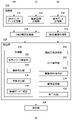
- the processing unit 220 includes a control unit 230 , a line-of-sight direction determination unit 250 , a map holding unit 252 , a vibration waveform holding unit 254 , an image generation unit 256 and a sound generation unit 258 .
- the control unit 230 has a virtual device control unit 232 , a relationship identification unit 234 , an action determination unit 236 and a driving data generation unit 238 .
- the line-of-sight direction determining unit 250 determines the line-of-sight direction of the user according to the posture information of the HMD 100 .
- the line-of-sight direction determination unit 250 converts the posture information of the HMD 100 into the line-of-sight direction of the user, and supplies the converted line-of-sight direction to the image generation unit 256 .
- the image generation unit 256 uses the line-of-sight direction provided from the line-of-sight direction determination unit 250 as information for determining the line-of-sight direction of the player character in the virtual space.
- Image generation unit 256 determines the position and direction of the virtual camera based on the position information of HMD 100 acquired by HMD information acquisition unit 210 and the line-of-sight direction determined by line-of-sight direction determination unit 250, and generates an application image. may be generated.
- the virtual device control unit 232 controls movement of the virtual device 22 in the virtual space according to operation information indicating movement of the operation device 20 . Specifically, the virtual device control unit 232 periodically acquires the orientation information and the position information of the operation device 20 from the operation information acquisition unit 212, and controls the virtual device in the virtual space according to the orientation information and the position information of the operation device 20. 22 are determined, and the virtual device 22 in the virtual space is linked with the movement of the operating device 20 in the real space.
- the player character dips the pen tip of the virtual device 22 into the inkwell in the virtual space to determine the color of the line to be drawn.
- the user moves the operation device 20 while pressing the operation button 42, thereby drawing the trajectory of the tip of the operation device 20 in the virtual space.
- a line drawn in the virtual three-dimensional space serves as a shield that protects the player character, and can be used to protect the player character from flying virtual objects (cannonballs).
- the operation device 20 provides the user with haptic feedback and/or haptic feedback, so that the user can experience the effects of actions in the virtual space. The action of each scene in the application will be described below.
- FIG. 9 shows an example of an image displayed on the display panel 130 of the HMD 100.
- the display panel 130 displays a plurality of inkwells 70a, 70b, 70c filled with ink.
- a plurality of ink reservoirs 70a, 70b, and 70c are arranged at predetermined positions in the virtual space and filled with inks of different colors.
- the ink reservoir 70a is filled with red ink 72a
- the ink reservoir 70b is filled with blue ink 72b
- the ink reservoir 70c is filled with yellow ink 72c.
- the user moves the virtual device 22 over the inkwell 70 of the desired color and dips the pen tip into the ink.
- illustration of the player character holding the virtual device 22 is omitted.
- FIG. 10 shows how the virtual device 22 enters the blue ink 72b of the ink reservoir 70b.
- FIG. 10(a) shows the pen tip slightly below the ink surface
- FIG. 10(b) shows about half of the virtual device 22 entering the blue ink 72b.
- the virtual device control unit 232 controls movement of the virtual device 22 according to the orientation information and position information of the operating device 20 .
- the relationship identifying unit 234 identifies the relative relationship between the virtual device 22 and the blue ink 72b that is the virtual object. Determine the action on device 20 .
- the action determination unit 236 may determine the action of the contact between the two.
- the relationship identifying unit 234 identifies the positional relationship between the virtual device 22 and the blue ink 72b from the three-dimensional coordinates of the ink reservoir 70b placed at a predetermined position and the three-dimensional coordinates of the virtual device 22. In the embodiment, the relationship identifying unit 234 derives the length of the virtual device 22 that has entered the blue ink 72b (entrance length L) from the identified positional relationship.
- the action determining unit 236 determines to move the movable unit 32 as the force sense presenting unit in the direction to pull it toward the base 30 when the virtual device 22 enters the blue ink 72b. At this time, the action determination section 236 derives the amount of movement of the movable section 32, which is the haptic presentation section, based on the approach length L.
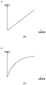
- FIG. 11(a) shows an example of a map that defines the relationship between the approach length L and the amount of movement of the movable portion 32.
- FIG. This relationship is held as a map in the map holding section 252, and the amount of movement indicates the amount of retraction of the movable section 32 from the reference position. Since the relationship shown in FIG. 11A is proportional to the length of entry and the amount of movement, the movable portion 32 is drawn into the base 30 in proportion to the length of the virtual device 22 entering the blue ink 72b.
- the action determination unit 236 When the action determination unit 236 receives the entry length L from the relationship identification unit 234 , the action determination unit 236 refers to the map held in the map holding unit 252 to acquire the movement amount corresponding to the entry length L, and passes it to the drive data generation unit 238 . .
- the drive data generator 238 generates first drive data for driving the movable part 32 based on the movement amount.
- the map holding unit 252 may hold a map defining the relationship between the approach length L and the amount of movement of the movable unit 32 for each virtual object.
- the map holding unit 252 may hold different maps for the red ink 72a, the blue ink 72b, and the yellow ink 72c.
- FIG. 11(b) shows another example of a map that defines the relationship between the approach length L and the amount of movement of the movable portion 32.
- FIG. 11B is a movement profile in which when the virtual device 22 begins to enter the ink, the movable portion 32 moves greatly, and after the virtual device 22 has entered the ink to some extent, the movable portion 32 gradually moves.
- the map holding unit 252 holds a map that defines the relationship between the approach length and the amount of movement for each virtual object (ink in this embodiment), so that the user can feel the virtual device through the haptic sensation presented by the movable unit 32. A resistance peculiar to the virtual object with which 22 is in contact can be felt.
- the relationship identifying unit 234 identifies the relative velocity between the virtual device 22 and the blue ink 72b that is the virtual object
- the action determining unit 236 identifies the relative speed identified by the relationship identifying unit 234. The action on the operating device 20 is determined based on the velocity.
- the relationship identifying unit 234 identifies the speed (moving speed) at which the virtual device 22 enters the blue ink 72b. Since the virtual object blue ink 72b is stationary, the moving speed of the virtual device 22 is equal to the relative speed between the virtual device 22 and the blue ink 72b.
- the action determination unit 236 derives the vibration profile of the vibration unit 40 as the tactile sense presentation unit based on the moving speed of the virtual device 22 .
- the vibration profile may be defined by the vibration waveform and the vibration amount.
- FIGS. 12(a) to (c) show examples of vibration waveforms.
- the horizontal axis indicates time.
- the vibration waveform holding unit 254 holds a vibration waveform, which is a pattern for vibrating the vibrating unit 40, for each virtual object.
- the vibration waveforms shown in FIGS. 12(a) and 12(b) are periodic, and the vibration waveform shown in FIG. 12(c) is aperiodic.
- the vibration waveform may be freely set for each virtual object.
- the vibration waveform is a normalized vibration pattern, and the vibration profile of the vibrating section 40 is derived by multiplying the vibration waveform by the vibration amount (amplitude) determined according to the moving speed.
- FIG. 13(a) shows an example of a map that defines the relationship between the moving speed and the amount of vibration of the vibrating section 40.
- FIG. This relationship is held as a map in the map holding unit 252, and the vibration amount indicates the amplitude of the vibration waveform. Since the relationship shown in FIG. 13A is proportional to the moving speed and the vibration amount (amplitude), the vibration amplitude of the vibrating section 40 increases in proportion to the moving speed of the virtual device 22 .
- the action determining unit 236 refers to the map held in the map holding unit 252 to obtain the vibration amount corresponding to the moving speed, and obtains the vibration amount stored in the vibration waveform holding unit 254.
- the vibration profile is derived by multiplying the vibration waveform corresponding to the virtual object by the vibration amount.
- the action determination unit 236 passes the derived vibration profile to the drive data generation unit 238, and the drive data generation unit 238 generates second drive data for driving the vibration unit 40 based on the vibration profile.
- the map holding unit 252 may hold a map defining the relationship between the moving speed and the vibration amount of the vibrating unit 40 for each virtual object.
- the map holding unit 252 may hold different maps for the red ink 72a, the blue ink 72b, and the yellow ink 72c.
- FIG. 13(b) shows another example of a map that defines the relationship between the moving speed and the amount of vibration of the vibrating section 40.
- the map holding unit 252 holds a map that defines the relationship between the moving speed and the amount of vibration for each virtual object (ink in this embodiment), so that the user can operate the virtual device 22 with the tactile sensation presented by the vibrating unit 40. You can feel the peculiar properties of the virtual object that is in contact with.
- the transmission unit 260 transmits the first driving data and the second driving data generated by the driving data generating unit 238 to the operating device 20.
- the control section 50 drives the movable section 32 based on the first drive data, and drives the vibrating section 40 based on the second drive data. Therefore, the movable part 32 is pulled into the base 30 by a movement amount corresponding to the approach length of the virtual device 22 , and at the same time the vibrating part 40 vibrates with a vibration profile corresponding to the moving speed of the virtual device 22 .
- the information processing system 1 of the embodiment by simultaneously providing haptic feedback and tactile feedback in response to the operation of the operation device 20, the entertainment of the application can be improved.
- FIG. 14 shows an example of an image displayed on the display panel 130 of the HMD 100.
- the user presses the operation button 42 and moves the operating device 20 in the real space. drawn.
- the relationship identifying section 234 identifies the moving speed of the virtual device 22
- the action determining section 236 determines the action for the operating device 20 based on the moving speed identified by the relationship identifying section 234 .
- the relationship identifying unit 234 identifies the moving speed of the virtual device 22 from the moving speed of the operating device 20 whose operation button 42 is pressed.
- the action determination unit 236 derives the vibration profile of the vibration unit 40 as the tactile sense presentation unit based on the moving speed of the virtual device 22 .
- the vibration profile may be defined by the vibration waveform and the vibration amount.
- the drive data generation section 238 generates second drive data for driving the vibration section 40 based on the vibration profile.
- the vibration waveform holding section 254 may hold a vibration waveform, which is a pattern for vibrating the vibrating section 40, for each ink color. Further, the map holding section 252 may hold a map that defines the relationship between the movement speed and the vibration amount of the vibrating section 40 for each ink color.
- FIG. 15 shows an example of an image displayed on the display panel 130 of the HMD 100.
- lines drawn by the user are used as shields to maintain their shape and prevent flying virtual objects.
- a shield 24 is attached to the tip of the virtual device 22, and the user directs the shield 24 in the direction in which the virtual object (cannonball in this example) is flying to guard the player character from the virtual object.
- the relationship identifying unit 234 identifies the relative relationship between the virtual device 22 and the shield 24 and the artillery shell that is the virtual object, and the action determining unit 236 based on the relative relationship identified by the relationship identifying unit 234, It determines the action on the operating device 20 .
- the effect determination unit 236 may determine the effect of the contact between the two.
- the relationship identifying unit 234 determines the collision between the virtual object and the shield 24 from the three-dimensional coordinates of the virtual object, which is the cannonball, and the three-dimensional coordinates of the shield 24 .
- the action determining section 236 determines to drive the movable section 32 as the force sense presenting section.
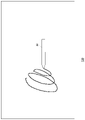
- FIG. 16 shows an example of a map that defines the relationship between the elapsed time from the collision and the amount of movement of the movable part 32.
- FIG. This relationship is held as a map in the map holding section 252, and the amount of movement indicates the amount of retraction of the movable section 32 from the reference position.
- the map holding unit 252 may hold a map defining the relationship between the elapsed time from the collision and the amount of movement of the movable part 32 for each virtual object. For example, maps may be set according to the types and sizes of virtual objects.
- the relationship identifying unit 234 identifies the relative velocity between the virtual device 22 and the artillery shell that is the virtual object
- the action determining unit 236 determines the relative velocity identified by the relationship identifying unit 234.
- the action to the operation device 20 is determined.
- the action determination unit 236 derives the vibration profile of the vibration unit 40, which is the tactile sense presentation unit, based on the relative speed between the virtual device 22 and the virtual object.
- the vibration profile may be defined by the vibration waveform and the vibration amount.
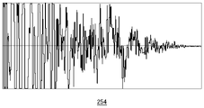
- FIG. 17 shows an example of vibration waveforms.
- the horizontal axis indicates the elapsed time from the collision.
- the vibration waveform holding unit 254 holds a vibration waveform, which is a pattern for vibrating the vibrating unit 40, for each colliding virtual object.
- the action determining unit 236 refers to the map held in the map holding unit 252 to obtain the vibration amount corresponding to the moving speed, and obtains the vibration amount stored in the vibration waveform holding unit 254.
- the vibration profile is derived by multiplying the vibration waveform corresponding to the virtual object by the vibration amount.
- the action determination unit 236 passes the derived vibration profile to the drive data generation unit 238, and the drive data generation unit 238 generates second drive data for driving the vibration unit 40 based on the vibration profile.
- the transmission unit 260 transmits the first driving data and the second driving data generated by the driving data generating unit 238 to the operating device 20.
- the control section 50 drives the movable section 32 based on the first drive data, and drives the vibrating section 40 based on the second drive data.
- the entertainment of the application can be improved.
- control unit 230 executes the VR application, but applications other than the VR application may be executed.
- the action determination unit 236 derives the vibration profile, and the drive data generation unit 238 generates the second drive data according to the vibration profile.
- action determiner 236 may apply the vibration profile derivation technique to sound effects, and sound generator 258 may generate sounds synchronized with haptic feedback.
- the present invention can be used for techniques that provide haptic feedback and/or haptic feedback to the user.
Landscapes
- Engineering & Computer Science (AREA)
- Multimedia (AREA)
- Human Computer Interaction (AREA)
- Theoretical Computer Science (AREA)
- General Engineering & Computer Science (AREA)
- Physics & Mathematics (AREA)
- General Physics & Mathematics (AREA)
- Software Systems (AREA)
- Computer Hardware Design (AREA)
- Computer Graphics (AREA)
- Architecture (AREA)
- Computer Networks & Wireless Communication (AREA)
- User Interface Of Digital Computer (AREA)
- Position Input By Displaying (AREA)
Abstract
操作情報取得部212は、ユーザの手に把持される操作装置の動きを示す操作情報を取得する。操作装置は、ユーザの手に力覚を提示する力覚提示部と、ユーザの手に触覚を提示する触覚提示部とを備える。制御部230は、仮想オブジェクトが存在する空間内で、操作装置に対応する仮想デバイスの動きを操作情報に応じて制御する。制御部230は、仮想デバイスと仮想オブジェクトとの関係にもとづいて、力覚提示部を駆動するための第1駆動データおよび触覚提示部を駆動するための第2駆動データを生成する。
Description
本発明は、ユーザに力覚フィードバックおよび/または触覚フィードバックを提供する技術に関する。
特許文献1は、筐体と、筐体に結合される質量体と、筐体に対する質量体の位置を変更するために質量体に結合されるアクチュエータとを備える携帯コンピュータインタフェースを開示する。特許文献1に開示された携帯コンピュータインタフェースはゲームの操作装置として利用され、質量体を移動させることで、ユーザにフィードバックを提供する。
ヘッドマウントディスプレイ(Head Mounted Display : HMD)はユーザの頭部に装着されて仮想現実(Virtual Reality : VR)の映像世界をユーザに提供する。最近ではHMDをゲーム装置に接続し、ユーザがHMDに表示されたゲーム画像を見ながら、操作装置を操作してゲームをプレイすることが一般的となっている。
ゲームプレイ中、ユーザは操作装置を通じてゲームからフィードバックを与えられることで、ゲーム操作の結果をリアルに体感できる。そのためユーザに力覚フィードバックおよび/または触覚フィードバックを効果的に提供することで、ゲームなどのアプリケーションのエンタテインメント性を向上できると考えられる。
本発明はこうした状況に鑑みてなされたものであり、その目的は、ユーザに力覚フィードバックおよび/または触覚フィードバックを提供する技術を実現することにある。
上記課題を解決するために、本発明のある態様の情報処理装置は、ユーザの手に把持される操作装置の動きを示す操作情報を取得する操作情報取得部と、仮想オブジェクトが存在する空間内で、操作装置に対応する仮想デバイスの動きを操作情報に応じて制御する制御部と、を備えた情報処理装置であって、操作装置は、ユーザの手に力覚を提示する力覚提示部と、ユーザの手に触覚を提示する触覚提示部とを備えており、制御部は、仮想デバイスと仮想オブジェクトとの関係にもとづいて、力覚提示部を駆動するための第1駆動データおよび触覚提示部を駆動するための第2駆動データを生成する。
本発明の別の態様の駆動データ生成方法は、ユーザの手に把持される操作装置の動きを示す操作情報を取得するステップと、仮想オブジェクトが存在する空間内で、操作装置に対応する仮想デバイスの動きを操作情報に応じて制御するステップと、仮想デバイスと仮想オブジェクトとの関係にもとづいて、ユーザの手に力覚を提示する力覚提示部を駆動するための第1駆動データおよびユーザの手に触覚を提示する触覚提示部を駆動するための第2駆動データを生成するステップと、を有する。
なお、以上の構成要素の任意の組合せ、本発明の表現を方法、装置、システムなどの間で変換したものもまた、本発明の態様として有効である。
図1は、実施例における情報処理システム1の構成例を示す。情報処理システム1は情報処理装置10と、記録装置11と、ユーザの頭部に装着されるヘッドマウントディスプレイ(HMD)100と、ユーザの手に把持される操作装置20と、HMD100および操作装置20を撮影する撮像装置14と、画像および音を出力する出力装置15とを備える。出力装置15はテレビであってよい。情報処理装置10は、アクセスポイント(AP)17を介して、インターネットなどの外部のネットワーク2に接続される。AP17は無線アクセスポイントおよびルータの機能を有し、情報処理装置10はAP17とケーブルで接続してもよく、または既知の無線通信プロトコルで接続してもよい。
記録装置11は、システムソフトウェアや、ゲームソフトウェアなどのアプリケーションを記録する。情報処理装置10は、コンテンツサーバからネットワーク2経由で、アプリケーションを記録装置11にダウンロードしてよい。情報処理装置10はアプリケーションを実行して、アプリケーションの画像データおよび音データをHMD100および出力装置15に供給する。情報処理装置10とHMD100とは既知の無線通信プロトコルで接続されてもよく、またはケーブルで接続されてもよい。
HMD100は、ユーザが頭部に装着することによりその眼前に位置する表示パネルに画像を表示する表示装置である。HMD100は、左目用表示パネルに左目用の画像を、右目用表示パネルに右目用の画像を、それぞれ別個に表示する。これらの画像は左右の視点から見た視差画像を構成し、立体視を実現する。ユーザは光学レンズを通して表示パネルを見るため、情報処理装置10は、レンズによる光学歪みを補正した視差画像データをHMD100に供給する。
HMD100は仮想現実(VR)の映像世界をユーザに提供する。情報処理システム1にヘッドトラッキング機能をもたせ、ユーザの頭部の動きに連動して表示画像を更新することで、映像世界への没入感を高められる。
HMD100を装着したユーザにとって出力装置15は必要ないが、出力装置15を用意することで、別のユーザが出力装置15の表示画像を見ることができる。情報処理装置10は、HMD100を装着したユーザが見ている画像と同じ画像を出力装置15に表示させてもよいが、別の画像を表示させてもよい。たとえばHMDを装着したユーザと、別のユーザとが一緒にゲームをプレイするような場合、出力装置15からは、当該別のユーザのキャラクタ視点からのゲーム画像が表示されてもよい。
操作装置20はバッテリにより駆動され、アプリケーションに対する操作を入力するための1つ以上の操作ボタンを備えるコントローラである。ユーザが操作装置20の操作ボタンを操作すると、その操作入力が無線通信により情報処理装置10に送信される。操作装置20と情報処理装置10の間には、たとえばBluetooth(登録商標)プロトコルを用いた無線接続が確立されてよい。情報処理装置10は操作装置20から操作入力を受信し、操作入力に応じてアプリケーションの進行を制御して、アプリケーションの画像データおよび音データを生成し、HMD100および出力装置15に供給する。操作装置20は無線コントローラに限らず、情報処理装置10とケーブルを介して接続される有線コントローラであってもよい。
操作装置20は、3軸の加速度センサおよび3軸のジャイロセンサを含む姿勢センサを備え、所定の周期でセンサデータを情報処理装置10に送信する。実施例の描画アプリケーションは、ユーザの手に把持される操作装置20の動きに合わせて、仮想3次元空間内で操作装置20に対応する仮想デバイス22を動かす。そのため情報処理装置10は、操作装置20から送信されるセンサデータをもとに、操作装置20の位置、姿勢および/または動きを導出し、導出した操作装置20の位置、姿勢および/または動きを、仮想デバイス22を動かすための操作情報として利用する。
撮像装置14は、CCD撮像素子またはCMOS撮像素子などから構成されるビデオカメラであり、実空間を所定の周期で撮影して、周期ごとのフレーム画像を生成する。撮像装置14はステレオカメラであって、情報処理装置10が、撮影画像から対象物との距離を測定できることが好ましい。撮像装置14の撮影速度は60枚/秒として、HMD100のフレームレートと一致させてもよい。撮像装置14は、USB(Universal Serial Bus)あるいはその他のインタフェースを介して情報処理装置10と接続する。
HMD100にはユーザ頭部をトラッキングするためのマーカ(トラッキング用LED)が設けられ、情報処理装置10は、撮影画像に含まれるマーカの位置にもとづいてHMD100の動きを検出する。なおHMD100には姿勢センサ(3軸加速度センサおよび3軸ジャイロセンサ)が搭載され、情報処理装置10は、姿勢センサで検出されたセンサデータをHMD100から取得することで、マーカの撮影画像の利用とあわせて、高精度のトラッキング処理を実施し、実空間におけるユーザ頭部(実際にはHMD100)の位置および姿勢を検出してよい。
ここでHMD100の位置とは、基準位置を原点とした3次元空間における位置座標であり、基準位置はHMD100の電源がオンされたときの位置座標(緯度、経度)であってよい。またHMD100の姿勢とは、3次元空間における基準姿勢に対する3軸方向の傾きであり、基準姿勢は、ユーザの視線方向が水平方向となる姿勢であって、HMD100の電源がオンされたときに基準姿勢が設定されてよい。なおトラッキング処理については従来より様々な手法が提案されており、情報処理装置10はHMD100の動きを検出できるのであれば、どのようなトラッキング手法を採用してもよい。
図2は、HMD100の外観形状の例を示す。HMD100は、出力機構部102および装着機構部104から構成される。装着機構部104は、ユーザが被ることにより頭部を一周してHMD100を頭部に固定する装着バンド106を含む。装着バンド106はユーザの頭囲に合わせて長さの調節が可能な素材または構造をもつ。
出力機構部102は、HMD100をユーザが装着した状態において左右の目を覆う形状の筐体108を含み、内部には装着時に目に正対する表示パネルを備える。表示パネルは液晶パネルや有機ELパネルなどであってよい。筐体108内部にはさらに、表示パネルとユーザの目との間に位置し、ユーザの視野角を拡大する左右一対の光学レンズが備えられる。HMD100はさらに、ユーザの耳に対応する位置にスピーカーやイヤホンを備えてよく、外付けのヘッドホンが接続されるように構成されてもよい。
筐体108の外面には、複数の発光マーカ110a、110b、110c、110dが備えられる。この例ではトラッキング用LEDが発光マーカ110を構成するが、その他の種類のマーカであってよく、いずれにしても撮像装置14により撮影されて、情報処理装置10がマーカ位置を画像解析できるものであればよい。発光マーカ110の数や配置は特に限定されないが、HMD100の姿勢を検出できるための数および配置である必要があり、図示した例では筐体108の前面の4隅に設けている。さらにユーザが撮像装置14に対して背を向けたときにも撮影できるように、発光マーカ110は装着バンド106の側部や後部に設けられてもよい。
図3は、HMD100の機能ブロックを示す。制御部120は、画像データ、音データ、センサデータなどの各種データや、命令を処理して出力するメインプロセッサである。記憶部122は、制御部120が処理するデータや命令などを一時的に記憶する。姿勢センサ124は、HMD100の姿勢情報を検出する。姿勢センサ124は、少なくとも3軸の加速度センサおよび3軸のジャイロセンサを含む。
通信制御部128は、ネットワークアダプタまたはアンテナを介して、有線または無線通信により、制御部120から出力されるデータを外部の情報処理装置10に送信する。また通信制御部128は、ネットワークアダプタまたはアンテナを介して、有線または無線通信により、情報処理装置10からデータを受信し、制御部120に出力する。
制御部120は、画像データや音データを情報処理装置10から受け取ると、表示パネル130に供給して表示させ、また音出力部132に供給して出力させる。表示パネル130は、左目用表示パネル130aと右目用表示パネル130bから構成され、各表示パネルに一対の視差画像が表示される。また制御部120は、姿勢センサ124からのセンサデータや、マイク126からの音声データを、通信制御部128から情報処理装置10に送信させる。
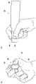
図4は、実施例の操作装置20をユーザが把持した状態を示す。図4(a)は、操作装置20を正面から見た状態を示し、図4(b)は、操作装置20を側面から見た状態を示す。操作装置20は、ユーザの手で把持される基体30と、基体30に対して相対移動可能な可動部32とを備える。可動部32は、ユーザの手に力覚を提示する力覚提示部として機能し、情報処理装置10から送信される駆動データにもとづいて駆動されて、ユーザに力覚フィードバックを提供する。
操作装置20はペン型のハプティクスデバイスであり、基体30は略平行に配置される両側面をもつ。ユーザは基体30の両側面を親指と中指で挟持し、人差し指を可動部32に置いた状態で、操作装置20を使用する。
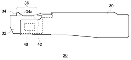
図5は、操作装置20の側面図である。操作装置20において、可動部32が設けられている側が先端側と定義され、図5に示す側面視にて左側を前側、右側を後側と呼ぶ。図5に示す状態で可動部32は基体30から前方に最も突き出た位置にあり、この位置が可動部32の「基準位置」となる。
可動部32の上面には、ユーザが基体30を把持した状態で、人差し指の指先を置くための指置き部36が設けられる。指置き部36の前端には、指の先端部分が係合する指係合部34が設けられる。指係合部34は、可動部32の移動方向(つまり前後方向)とは異なる向きに立設され、実施例で指係合部34は、可動部32の上面に垂直な方向に立設されている。指係合部34は、指の腹に沿うように傾斜し且つ曲率を有する湾曲面34aを有する。湾曲面34aが、可動部32の上面に対して傾斜し且つ指先を接触させる方向に凹状に形成されていることで、ユーザは、人差し指の先端部分を安定して湾曲面34aに接触させることができる。
ユーザは、ペンを持つように親指と中指で基体30の両側面を挟持し、人差し指の腹を指置き部36に置く。このためユーザは利き手に関係なく、人差し指を指置き部36に置くことができる。基体30の先端側の部分、具体的には親指または中指を配置される部分には、振動子を含む振動部40が設けられる。振動部40は、基体30先端の両側に設けられてもよい。振動部40は、ユーザの手に触覚を提示する触覚提示部として機能し、情報処理装置10から送信される駆動データにもとづいて駆動されて、ユーザに触覚フィードバックを提供する。
指置き部36には、人差し指先端により操作可能な操作ボタン42が設けられる。操作ボタン42はプッシュ式ボタンであって、ユーザは操作ボタン42を押し込むことで、接点構造を備えたスイッチ(図示せず)をオンする。操作ボタン42は、指置き部36において湾曲面34aより後方側に設けられる。操作ボタン42が指置き部36に設けられることで、ユーザは、基体30を親指と中指で挟持した状態で、操作ボタン42を人差し指で自由に操作できる。
図6(a)は、基準位置にある可動部32に指を置いた状態を示す。ユーザが指置き部36に指の腹を置くと、指の先端部分が湾曲面34aにフィットして接触する。このように指の先端部分が指係合部34に当接することで、可動部32が基体30に引き込まれる方向に動くときに、指が指係合部34とともに確実に移動する。
図6(b)は、可動部32が基体30に引き込まれる方向に移動する状態を示す。可動部32が移動するとき、指先端部は、指置き部36との間に作用する摩擦力により、可動部32に連動するように動く。このとき指先端部が、移動方向に対して垂直方向に立設されている指係合部34と接触していることで、可動部32の動きに確実に連動するようになる。
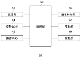
図7は、操作装置20の機能ブロックを示す。制御部50は、センサデータ、駆動データなどの各種データや、命令を処理して出力するメインプロセッサである。記憶部52は、制御部50が処理するデータや命令などを一時的に記憶する。姿勢センサ54は、操作装置20の姿勢情報を検出する。姿勢センサ54は、少なくとも3軸の加速度センサおよび3軸のジャイロセンサを含む。
通信制御部56は、ネットワークアダプタまたはアンテナを介して、有線または無線通信により、制御部50から出力されるデータを外部の情報処理装置10に送信する。また通信制御部50は、ネットワークアダプタまたはアンテナを介して、有線または無線通信により、情報処理装置10からデータを受信し、制御部50に出力する。
制御部50は、駆動データを情報処理装置10から受け取ると、可動部32および/または振動部40を駆動する。操作装置20において、可動部32は、ユーザの手に力覚を提示する力覚提示部であり、振動部40は、ユーザの手に触覚を提示する触覚提示部である。可動部32が触覚フィードバックを提供し、振動部40が触覚フィードバックを提供することで、ユーザは、アプリケーションで生じるイベントをリアルに体感できる。制御部50は、姿勢センサ54からのセンサデータを、通信制御部56から情報処理装置10に送信させる。
実施例の操作装置20は、仮想的な3次元空間に絵や文字を描く描画アプリケーションにおいて、インクを出す仮想デバイス22として利用される。仮想デバイス22は、ペン先を含む仮想ペンとして表示パネル130および出力装置15に表示される。この描画アプリケーションでは、操作装置20の先端部が仮想デバイス22のペン先に対応し、ユーザが実空間で操作装置20を動かすと、仮想デバイス22が仮想空間内で、操作装置20に連動した挙動を示す。
図8は、情報処理装置10の機能ブロックを示す。情報処理装置10は、外部との入出力インタフェースとして、受信部200および送信部260を備える。情報処理装置10は、さらにHMD情報取得部210、操作情報取得部212および処理部220を備える。
図8において、さまざまな処理を行う機能ブロックとして記載される各要素は、ハードウェア的には、回路ブロック、メモリ、その他のLSIで構成することができ、ソフトウェア的には、メモリにロードされたプログラムなどによって実現される。したがって、これらの機能ブロックがハードウェアのみ、ソフトウェアのみ、またはそれらの組合せによっていろいろな形で実現できることは当業者には理解されるところであり、いずれかに限定されるものではない。
HMDセンサデータ受信部202は、ユーザが装着したHMD100の姿勢センサ124のセンサデータを所定の周期で受信して、HMD情報取得部210に供給する。たとえばHMD100がセンサデータを送信する周期は、11.25m秒に設定されてよい。撮影画像受信部204は、撮像装置14から所定の周期でHMD100を撮影した画像を受信して、HMD情報取得部210に供給する。たとえば撮像装置14は(1/60)秒ごとに前方の空間を撮影し、撮影画像受信部204は、(1/60)秒ごとに撮影画像を受信してよい。操作データ受信部206は、ユーザが把持する操作装置20の姿勢センサ56のセンサデータおよび操作ボタン42の操作データを所定の周期で受信する。たとえば操作装置20がセンサデータおよび操作データを送信する周期は、11.25m秒に設定されてよい。操作データ受信部206は、姿勢センサ56のセンサデータおよび操作ボタン42の操作データを操作情報取得部212に供給する。
HMD情報取得部210は、HMD100のセンサデータと、撮影画像に含まれる複数の発光マーカ110の撮影状態から、実空間におけるHMD100の姿勢を示す姿勢情報と、HMD100の位置を示す位置情報を取得する。HMD情報取得部210は、撮影画像に含まれるトラッキング用の複数の発光マーカ110の傾きを算出し、算出した傾きと、3軸ジャイロセンサのセンサデータを用いて、HMD100の姿勢情報を取得してよい。またHMD情報取得部210は、基準位置からの移動量を、3軸加速度センサのセンサデータを用いて算出し、HMD100の位置情報を取得してよい。HMD情報取得部210は、HMD100の姿勢情報および位置情報を処理部220に供給する。
操作情報取得部212は、操作装置20のセンサデータから、実空間における操作装置20の姿勢を示す姿勢情報と、操作装置20の位置を示す位置情報を取得する。操作情報取得部212は、主として3軸ジャイロセンサのセンサデータを用いて操作装置20の姿勢情報を算出し、3軸加速度センサのセンサデータを用いて操作装置20の位置情報を算出する。操作装置20の姿勢情報および位置情報は、操作装置20の動きを示す操作情報である。操作情報取得部212は、操作装置20の姿勢情報および位置情報を、操作装置20の動きを示す操作情報として処理部220に供給する。また操作情報取得部212は、操作ボタン42の操作データを、処理部220に供給する。
処理部220は、制御部230、視線方向決定部250、マップ保持部252、振動波形保持部254、画像生成部256および音生成部258を備える。制御部230は、仮想デバイス制御部232、関係特定部234、作用決定部236および駆動データ生成部238を有する。
視線方向決定部250は、HMD100の姿勢情報に応じてユーザの視線方向を定める。視線方向決定部250は、HMD100の姿勢情報をユーザの視線方向に変換し、変換した視線方向を、画像生成部256に供給する。画像生成部256は、視線方向決定部250から提供される視線方向を、仮想空間におけるプレイヤキャラクタの視線方向を定める情報として利用する。画像生成部256は、HMD情報取得部210で取得されたHMD100の位置情報、および視線方向決定部250で決定された視線方向にもとづいて、仮想カメラの位置および方向を決定して、アプリケーション画像を生成してよい。
仮想デバイス制御部232は、操作装置20の動きを示す操作情報に応じて、仮想空間における仮想デバイス22の動きを制御する。具体的に仮想デバイス制御部232は、操作情報取得部212から周期的に操作装置20の姿勢情報および位置情報を取得し、操作装置20の姿勢情報および位置情報に応じて、仮想空間における仮想デバイス22の姿勢および位置を定めて、実空間における操作装置20の動きに、仮想空間における仮想デバイス22を連動させる。
実施例の描画アプリケーションでは、仮想空間において、プレイヤキャラクタが、仮想デバイス22のペン先をインク壺に浸して、描画する線の色を決める。この後、ユーザが操作ボタン42を押下しながら、操作装置20を動かすことで、仮想空間には、操作装置20の先端部の軌跡が描画される。仮想3次元空間に描かれた線は、プレイヤキャラクタを守るシールドとなり、プレイヤキャラクタを目がけて飛んでくる仮想オブジェクト(砲弾)から身を防ぐために利用できる。この一連の進行において、操作装置20が、ユーザに力覚フィードバックおよび/または触覚フィードバックを提供することで、ユーザは、仮想空間内での行動に対する作用を体感できる。以下、アプリケーションにおける各シーンの作用について説明する。
<ペン先をインク壺に浸すシーン>
図9は、HMD100の表示パネル130に表示される画像の例を示す。表示パネル130には、インクを充填された複数のインク壺70a、70b、70cが表示される。複数のインク壺70a、70b、70cは、仮想空間において所定の位置に配置され、それぞれ異なる色のインクを充填されている。ここでインク壺70aは赤インク72a、インク壺70bは青インク72b、インク壺70cは黄インク72cを充填されている。ユーザは仮想デバイス22を、使いたい色のインク壺70の上に動かし、ペン先をインクに浸す。なお図9、図14、図15に示す表示画像において、仮想デバイス22を持つプレイヤキャラクタの図示は省略している。
図9は、HMD100の表示パネル130に表示される画像の例を示す。表示パネル130には、インクを充填された複数のインク壺70a、70b、70cが表示される。複数のインク壺70a、70b、70cは、仮想空間において所定の位置に配置され、それぞれ異なる色のインクを充填されている。ここでインク壺70aは赤インク72a、インク壺70bは青インク72b、インク壺70cは黄インク72cを充填されている。ユーザは仮想デバイス22を、使いたい色のインク壺70の上に動かし、ペン先をインクに浸す。なお図9、図14、図15に示す表示画像において、仮想デバイス22を持つプレイヤキャラクタの図示は省略している。
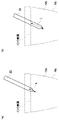
図10は、仮想デバイス22をインク壺70bの青インク72bに進入させる様子を示す。図10(a)は、ペン先が僅かにインク表面の下方に入り込んだ様子を、図10(b)は、仮想デバイス22の半分ほどが青インク72bに進入した様子を示す。仮想デバイス制御部232は、操作装置20の姿勢情報および位置情報に応じて、仮想デバイス22の動きを制御する。
関係特定部234は、仮想デバイス22と、仮想オブジェクトである青インク72bとの相対的な関係を特定し、作用決定部236は、関係特定部234が特定した相対的な関係にもとづいて、操作装置20に対する作用を決定する。実施例では仮想デバイス22と仮想オブジェクトとが接触したときに、作用決定部236が、両者が接触したことによる作用を決定してよい。
関係特定部234は、所定位置に配置されたインク壺70bの3次元座標と、仮想デバイス22の3次元座標から、仮想デバイス22と青インク72bの位置関係を特定する。実施例で関係特定部234は、特定した位置関係から、仮想デバイス22が青インク72bに進入した長さ(進入長L)を導出する。作用決定部236は、仮想デバイス22が青インク72bに進入すると、力覚提示部である可動部32を基体30に引き込む方向に移動させることを決定する。このとき作用決定部236は、進入長Lにもとづいて、力覚提示部である可動部32の移動量を導出する。
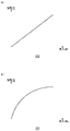
図11(a)は、進入長Lと、可動部32の移動量の関係を定めたマップの例を示す。この関係は、マップとして、マップ保持部252に保持されており、移動量は、可動部32の基準位置からの引込量を示す。図11(a)に示す関係は、進入長と移動量とが比例関係にあるため、仮想デバイス22が青インク72bに進入した長さに比例して、可動部32が基体30に引き込まれる。作用決定部236は、関係特定部234から進入長Lを受け取ると、マップ保持部252に保持されたマップを参照して進入長Lに応じた移動量を取得し、駆動データ生成部238に渡す。駆動データ生成部238は、移動量にもとづいて、可動部32を駆動するための第1駆動データを生成する。
マップ保持部252は、進入長Lと可動部32の移動量の関係を定義したマップを、仮想オブジェクトごとに保持してよい。たとえばマップ保持部252は、赤インク72a、青インク72b、黄インク72cに対して、それぞれ異なるマップを保持してよい。
図11(b)は、進入長Lと、可動部32の移動量の関係を定めたマップの別の例を示す。この関係は、マップ保持部252に保持される。図11(b)に示す関係は、仮想デバイス22がインクに進入し始めると、可動部32が大きく移動し、仮想デバイス22がある程度進入した後は、可動部32が徐々に移動する移動プロファイルをもつ。マップ保持部252が、仮想オブジェクト(実施例ではインク)ごとに、進入長と移動量の関係を定義したマップを保持することで、ユーザは、可動部32により提示される力覚によって、仮想デバイス22が接触している仮想オブジェクト特有の抵抗を感じることができる。
さらに実施例では、関係特定部234が、仮想デバイス22と、仮想オブジェクトである青インク72bとの間の相対的な速度を特定し、作用決定部236が、関係特定部234が特定した相対的な速度にもとづいて、操作装置20に対する作用を決定する。
関係特定部234は、仮想デバイス22が青インク72bに進入する速度(移動速度)を特定する。仮想オブジェクトである青インク72bは静止しているため、仮想デバイス22の移動速度は、仮想デバイス22と青インク72bとの間の相対的な速度に等しい。作用決定部236は、仮想デバイス22の移動速度にもとづいて、触覚提示部である振動部40の振動プロファイルを導出する。ここで振動プロファイルは、振動波形と、振動量によって定義されてよい。
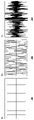
図12(a)~(c)は、振動波形の例を示す。横軸は時間を示す。振動波形保持部254は、仮想オブジェクトごとに、振動部40を振動させるパターンである振動波形を保持する。ここで図12(a)、(b)に示す振動波形は、周期的であり、図12(c)に示す振動波形は、非周期的である。このように振動波形は、仮想オブジェクトごとに自由に設定されてよい。振動波形は、正規化された振動パターンであり、移動速度に応じて決定される振動量(振幅)が振動波形に掛け合わされることで、振動部40の振動プロファイルが導出される。
図13(a)は、移動速度と、振動部40の振動量の関係を定めたマップの例を示す。この関係は、マップとして、マップ保持部252に保持されており、振動量は、振動波形の振幅を示す。図13(a)に示す関係は、移動速度と振動量(振幅)とが比例関係にあるため、仮想デバイス22の移動速度に比例して、振動部40の振動振幅が大きくなる。作用決定部236は、関係特定部234から移動速度を受け取ると、マップ保持部252に保持されたマップを参照して移動速度に応じた振動量を取得し、振動波形保持部254に保持された、仮想オブジェクトに対応する振動波形に振動量を乗算することで、振動プロファイルを導出する。作用決定部236は、導出した振動プロファイルを駆動データ生成部238に渡し、駆動データ生成部238は、振動プロファイルにもとづいて、振動部40を駆動するための第2駆動データを生成する。
マップ保持部252は、移動速度と振動部40の振動量の関係を定義したマップを、仮想オブジェクトごとに保持してよい。たとえばマップ保持部252は、赤インク72a、青インク72b、黄インク72cに対して、それぞれ異なるマップを保持してよい。
図13(b)は、移動速度と、振動部40の振動量の関係を定めたマップの別の例を示す。マップ保持部252は、仮想オブジェクト(実施例ではインク)ごとに、移動速度と振動量の関係を定義したマップを保持することで、ユーザは、振動部40により提示される触覚によって、仮想デバイス22が接触している仮想オブジェクト特有の性質を感じることができる。
送信部260は、駆動データ生成部238が生成した第1駆動データおよび第2駆動データを操作装置20に送信する。操作装置20において制御部50は、第1駆動データにもとづいて可動部32を駆動し、第2駆動データにもとづいて振動部40を駆動する。したがって可動部32は、仮想デバイス22の進入長に応じた移動量で、基体30に引き込まれ、同時に振動部40が、仮想デバイス22の移動速度に応じた振動プロファイルで振動する。実施例の情報処理システム1によると、操作装置20の操作に対して、力覚フィードバックと触覚フィードバックとを同時に提供することで、アプリケーションのエンタテイメント性を向上できる。
<空間にインクで線を描くシーン>
図14は、HMD100の表示パネル130に表示される画像の例を示す。仮想デバイス22のペン先を青インク72bに浸した後、ユーザが操作ボタン42を押下しながら、実空間で操作装置20を動かすことで、仮想空間には、操作装置20の先端部の軌跡が描画される。このシーンでは、関係特定部234が、仮想デバイス22の移動速度を特定し、作用決定部236が、関係特定部234が特定した移動速度にもとづいて、操作装置20に対する作用を決定する。
図14は、HMD100の表示パネル130に表示される画像の例を示す。仮想デバイス22のペン先を青インク72bに浸した後、ユーザが操作ボタン42を押下しながら、実空間で操作装置20を動かすことで、仮想空間には、操作装置20の先端部の軌跡が描画される。このシーンでは、関係特定部234が、仮想デバイス22の移動速度を特定し、作用決定部236が、関係特定部234が特定した移動速度にもとづいて、操作装置20に対する作用を決定する。
関係特定部234は、操作ボタン42が押下されている操作装置20の移動速度から、仮想デバイス22の移動速度を特定する。作用決定部236は、仮想デバイス22の移動速度にもとづいて、触覚提示部である振動部40の振動プロファイルを導出する。上記したように振動プロファイルは、振動波形と、振動量によって定義されてよい。駆動データ生成部238は、振動プロファイルにもとづいて、振動部40を駆動するための第2駆動データを生成する。
振動波形保持部254は、インクの色ごとに、振動部40を振動させるパターンである振動波形を保持してよい。またマップ保持部252は、インクの色ごとに、移動速度と、振動部40の振動量の関係を定めたマップを保持してよい。インクの色に応じた振動波形および振動量を用意することで、描く線の色に応じた触覚フィードバックをユーザに提供でき、ユーザは、線の色による触覚フィードバックの違いを楽しむことができる。
<描いた線をシールドとして利用するシーン>
図15は、HMD100の表示パネル130に表示される画像の例を示す。描画アプリケーションにおいて、ユーザが描いた線は、その形状を維持して、飛んでくる仮想オブジェクトを防ぐためのシールドとして用いられる。このシーンでは、仮想デバイス22の先端にシールド24が装着され、ユーザは、仮想オブジェクト(この例では砲弾)が飛んで来る方向にシールド24を向けて、仮想オブジェクトからプレイヤキャラクタをガードする。
図15は、HMD100の表示パネル130に表示される画像の例を示す。描画アプリケーションにおいて、ユーザが描いた線は、その形状を維持して、飛んでくる仮想オブジェクトを防ぐためのシールドとして用いられる。このシーンでは、仮想デバイス22の先端にシールド24が装着され、ユーザは、仮想オブジェクト(この例では砲弾)が飛んで来る方向にシールド24を向けて、仮想オブジェクトからプレイヤキャラクタをガードする。
関係特定部234は、仮想デバイス22およびシールド24と、仮想オブジェクトである砲弾との相対的な関係を特定し、作用決定部236は、関係特定部234が特定した相対的な関係にもとづいて、操作装置20に対する作用を決定する。実施例ではシールド24と仮想オブジェクトとが接触したときに、作用決定部236が、両者が接触したことによる作用を決定してよい。
関係特定部234は、砲弾である仮想オブジェクトの3次元座標と、シールド24の3次元座標から、仮想オブジェクトとシールド24の衝突を判定する。作用決定部236は、仮想オブジェクトとシールド24の衝突が判定されると、力覚提示部である可動部32を駆動することを決定する。
図16は、衝突からの経過時間と、可動部32の移動量の関係を定めたマップの例を示す。この関係は、マップとして、マップ保持部252に保持されており、移動量は、可動部32の基準位置からの引込量を示す。マップ保持部252は、衝突からの経過時間と、可動部32の移動量の関係を定義したマップを、仮想オブジェクトごとに保持してよい。たとえばマップは、仮想オブジェクトの種類や大きさに応じて設定されてよい。作用決定部236は、関係特定部234から衝突したことを通知されると、マップ保持部252に保持されたマップを読み出して、駆動データ生成部238に渡す。駆動データ生成部238は、マップに定められる移動プロファイルにもとづいて、可動部32を駆動するための第1駆動データを生成する。
さらに実施例では、関係特定部234が、仮想デバイス22と、仮想オブジェクトである砲弾との間の相対的な速度を特定し、作用決定部236が、関係特定部234が特定した相対的な速度にもとづいて、操作装置20に対する作用を決定する。具体的に作用決定部236は、仮想デバイス22と仮想オブジェクトとの間の相対的な速度にもとづいて、触覚提示部である振動部40の振動プロファイルを導出する。ここで振動プロファイルは、振動波形と、振動量によって定義されてよい。
図17は、振動波形の例を示す。横軸は、衝突からの経過時間を示す。振動波形保持部254は、衝突する仮想オブジェクトごとに、振動部40を振動させるパターンである振動波形を保持する。作用決定部236は、関係特定部234から移動速度を受け取ると、マップ保持部252に保持されたマップを参照して移動速度に応じた振動量を取得し、振動波形保持部254に保持された、仮想オブジェクトに対応する振動波形に振動量を乗算することで、振動プロファイルを導出する。作用決定部236は、導出した振動プロファイルを駆動データ生成部238に渡し、駆動データ生成部238は、振動プロファイルにもとづいて、振動部40を駆動するための第2駆動データを生成する。
送信部260は、駆動データ生成部238が生成した第1駆動データおよび第2駆動データを操作装置20に送信する。操作装置20において制御部50は、第1駆動データにもとづいて可動部32を駆動し、第2駆動データにもとづいて振動部40を駆動する。実施例の情報処理システム1によると、操作装置20の操作に対して、力覚フィードバックと触覚フィードバックとを同時に提供することで、アプリケーションのエンタテイメント性を向上できる。
以上、本発明を実施例をもとに説明した。この実施例は例示であり、その各構成要素や各処理プロセスの組合せにいろいろな変形が可能なこと、またそうした変形例も本発明の範囲にあることは当業者に理解されるところである。実施例では、制御部230が、VRアプリケーションを実施することを説明したが、VRアプリケーション以外のアプリケーションを実施してもよい。
実施例では、作用決定部236が振動プロファイルを導出して、駆動データ生成部238が、振動プロファイルに応じた第2駆動データを生成している。変形例では、作用決定部236が、振動プロファイルを導出する手法をサウンドエフェクトにも適用して、音生成部258が、触覚フィードバックと同期した音を生成してもよい。
本発明は、ユーザに力覚フィードバックおよび/または触覚フィードバックを提供する技術に利用できる。
1・・・情報処理システム、10・・・情報処理装置、20・・・操作装置、22・・・仮想デバイス、24・・・シールド、30・・・基体、32・・・可動部、34・・・指係合部、34a・・・湾曲面、36・・・指置き部、40・・・振動部、42・・・操作ボタン、50・・・制御部、52・・・記憶部、54・・・姿勢センサ、56・・・通信制御部、200・・・受信部、202・・・HMDセンサデータ受信部、204・・・撮影画像受信部、206・・・操作データ受信部、210・・・HMD情報取得部、212・・・操作情報取得部、220・・・処理部、230・・・制御部、232・・・仮想デバイス制御部、234・・・関係特定部、236・・・作用決定部、238・・・駆動データ生成部、250・・・視線方向決定部、252・・・マップ保持部、254・・・振動波形保持部、256・・・画像生成部、258・・・音生成部、260・・・送信部。
Claims (6)
- ユーザの手に把持される操作装置の動きを示す操作情報を取得する操作情報取得部と、
仮想オブジェクトが存在する空間内で、操作装置に対応する仮想デバイスの動きを操作情報に応じて制御する制御部と、を備えた情報処理装置であって、前記操作装置は、ユーザの手に力覚を提示する力覚提示部と、ユーザの手に触覚を提示する触覚提示部とを備えており、
前記制御部は、仮想デバイスと仮想オブジェクトとの関係にもとづいて、前記力覚提示部を駆動するための第1駆動データおよび前記触覚提示部を駆動するための第2駆動データを生成する、
ことを特徴とする情報処理装置。 - 前記力覚提示部は、前記操作装置の基体に対して相対移動する可動部であり、前記触覚提示部は、振動を発生する振動部である、
ことを特徴とする請求項1に記載の情報処理装置。 - 前記制御部は、仮想デバイスと仮想オブジェクトとの位置関係にもとづいて、前記力覚提示部を駆動するための第1駆動データを生成する、
ことを特徴とする請求項1または2に記載の情報処理装置。 - 前記制御部は、仮想デバイスと仮想オブジェクトとの間の相対的な速度にもとづいて、前記触覚提示部を駆動するための第2駆動データを生成する、
ことを特徴とする請求項1から3のいずれかに記載の情報処理装置。 - ユーザの手に把持される操作装置の動きを示す操作情報を取得するステップと、
仮想オブジェクトが存在する空間内で、操作装置に対応する仮想デバイスの動きを操作情報に応じて制御するステップと、
仮想デバイスと仮想オブジェクトとの関係にもとづいて、ユーザの手に力覚を提示する力覚提示部を駆動するための第1駆動データおよびユーザの手に触覚を提示する触覚提示部を駆動するための第2駆動データを生成するステップと、
を有することを特徴とする駆動データ生成方法。 - コンピュータに、
ユーザの手に把持される操作装置の動きを示す操作情報を取得する機能と、
仮想オブジェクトが存在する空間内で、操作装置に対応する仮想デバイスの動きを操作情報に応じて制御する機能と、
仮想デバイスと仮想オブジェクトとの関係にもとづいて、ユーザの手に力覚を提示する力覚提示部を駆動するための第1駆動データおよびユーザの手に触覚を提示する触覚提示部を駆動するための第2駆動データを生成する機能と、
を実現させるためのプログラム。
Priority Applications (4)
| Application Number | Priority Date | Filing Date | Title |
|---|---|---|---|
| PCT/JP2021/026415 WO2023286191A1 (ja) | 2021-07-14 | 2021-07-14 | 情報処理装置および駆動データ生成方法 |
| JP2023534811A JP7577218B2 (ja) | 2021-07-14 | 2022-07-12 | 情報処理装置、情報処理方法および駆動データ生成方法 |
| US18/577,883 US12528015B2 (en) | 2021-07-14 | 2022-07-12 | Information processing apparatus, information processing method, and driving data generation method |
| PCT/JP2022/027378 WO2023286761A1 (ja) | 2021-07-14 | 2022-07-12 | 情報処理装置、情報処理方法および駆動データ生成方法 |
Applications Claiming Priority (1)
| Application Number | Priority Date | Filing Date | Title |
|---|---|---|---|
| PCT/JP2021/026415 WO2023286191A1 (ja) | 2021-07-14 | 2021-07-14 | 情報処理装置および駆動データ生成方法 |
Publications (1)
| Publication Number | Publication Date |
|---|---|
| WO2023286191A1 true WO2023286191A1 (ja) | 2023-01-19 |
Family
ID=84919494
Family Applications (2)
| Application Number | Title | Priority Date | Filing Date |
|---|---|---|---|
| PCT/JP2021/026415 Ceased WO2023286191A1 (ja) | 2021-07-14 | 2021-07-14 | 情報処理装置および駆動データ生成方法 |
| PCT/JP2022/027378 Ceased WO2023286761A1 (ja) | 2021-07-14 | 2022-07-12 | 情報処理装置、情報処理方法および駆動データ生成方法 |
Family Applications After (1)
| Application Number | Title | Priority Date | Filing Date |
|---|---|---|---|
| PCT/JP2022/027378 Ceased WO2023286761A1 (ja) | 2021-07-14 | 2022-07-12 | 情報処理装置、情報処理方法および駆動データ生成方法 |
Country Status (3)
| Country | Link |
|---|---|
| US (1) | US12528015B2 (ja) |
| JP (1) | JP7577218B2 (ja) |
| WO (2) | WO2023286191A1 (ja) |
Families Citing this family (1)
| Publication number | Priority date | Publication date | Assignee | Title |
|---|---|---|---|---|
| JP7849823B2 (ja) * | 2023-09-06 | 2026-04-22 | 株式会社豊田中央研究所 | 触覚提示装置および触覚提示装置の制御方法 |
Citations (6)
| Publication number | Priority date | Publication date | Assignee | Title |
|---|---|---|---|---|
| JP2009294844A (ja) * | 2008-06-04 | 2009-12-17 | Saitama Univ | マウス及びマウスパッド |
| JP2010287221A (ja) * | 2009-05-11 | 2010-12-24 | Univ Of Tokyo | 力覚提示装置 |
| WO2018030266A1 (ja) * | 2016-08-09 | 2018-02-15 | 日本電産サンキョー株式会社 | ペン型触力覚提示デバイス |
| JP2019106102A (ja) * | 2017-12-14 | 2019-06-27 | 国立大学法人東京工業大学 | 硬さ感覚提示装置 |
| WO2019225170A1 (ja) * | 2018-05-21 | 2019-11-28 | 株式会社ワコム | 位置指示デバイス及び空間位置指示システム |
| JP2020194465A (ja) * | 2019-05-30 | 2020-12-03 | 学校法人立命館 | 触覚提示システム、触覚提示装置、コントローラ、及び仮想世界における触覚を実世界においてユーザに提示する方法 |
Family Cites Families (4)
| Publication number | Priority date | Publication date | Assignee | Title |
|---|---|---|---|---|
| JP2000200140A (ja) | 1999-01-06 | 2000-07-18 | Nippon Telegr & Teleph Corp <Ntt> | 力覚提示方法及び力覚ペンタブレット |
| US8698736B2 (en) | 2009-03-24 | 2014-04-15 | Immersion Corporation | Handheld computer interface with haptic feedback |
| US10579207B2 (en) * | 2014-05-14 | 2020-03-03 | Purdue Research Foundation | Manipulating virtual environment using non-instrumented physical object |
| JP6571539B2 (ja) | 2016-01-07 | 2019-09-04 | アルプスアルパイン株式会社 | 触覚再現装置 |
-
2021
- 2021-07-14 WO PCT/JP2021/026415 patent/WO2023286191A1/ja not_active Ceased
-
2022
- 2022-07-12 WO PCT/JP2022/027378 patent/WO2023286761A1/ja not_active Ceased
- 2022-07-12 JP JP2023534811A patent/JP7577218B2/ja active Active
- 2022-07-12 US US18/577,883 patent/US12528015B2/en active Active
Patent Citations (6)
| Publication number | Priority date | Publication date | Assignee | Title |
|---|---|---|---|---|
| JP2009294844A (ja) * | 2008-06-04 | 2009-12-17 | Saitama Univ | マウス及びマウスパッド |
| JP2010287221A (ja) * | 2009-05-11 | 2010-12-24 | Univ Of Tokyo | 力覚提示装置 |
| WO2018030266A1 (ja) * | 2016-08-09 | 2018-02-15 | 日本電産サンキョー株式会社 | ペン型触力覚提示デバイス |
| JP2019106102A (ja) * | 2017-12-14 | 2019-06-27 | 国立大学法人東京工業大学 | 硬さ感覚提示装置 |
| WO2019225170A1 (ja) * | 2018-05-21 | 2019-11-28 | 株式会社ワコム | 位置指示デバイス及び空間位置指示システム |
| JP2020194465A (ja) * | 2019-05-30 | 2020-12-03 | 学校法人立命館 | 触覚提示システム、触覚提示装置、コントローラ、及び仮想世界における触覚を実世界においてユーザに提示する方法 |
Non-Patent Citations (1)
| Title |
|---|
| KONYO, MASASHI: "A Display Method of Artificial Tactile Sensation Using Amplitude Modulation of Ultrasonic Vibration", THE 24TH ANNUAL CONFERENCE OF THE ROBOTICS SOCIETY OF JAPAN PROCEEDINGS CD-ROM; SEPTEMBER 14 - 16, 2006, ROBOTICS SOCIETY OF JAPAN, JP, vol. 2K13, 14 September 2006 (2006-09-14) - 16 September 2006 (2006-09-16), JP, pages 1 - 4, XP009542610 * |
Also Published As
| Publication number | Publication date |
|---|---|
| WO2023286761A1 (ja) | 2023-01-19 |
| US20240252924A1 (en) | 2024-08-01 |
| JP7577218B2 (ja) | 2024-11-01 |
| US12528015B2 (en) | 2026-01-20 |
| JPWO2023286761A1 (ja) | 2023-01-19 |
Similar Documents
| Publication | Publication Date | Title |
|---|---|---|
| US9884248B2 (en) | Display control method for head-mounted display (HMD) and image generation device | |
| US20200159389A1 (en) | Information processing method and apparatus for executing the information processing method | |
| JP6532393B2 (ja) | 表示制御装置及び表示制御方法 | |
| US10223064B2 (en) | Method for providing virtual space, program and apparatus therefor | |
| US20180357817A1 (en) | Information processing method, program, and computer | |
| US10564801B2 (en) | Method for communicating via virtual space and information processing apparatus for executing the method | |
| JP6518578B2 (ja) | 表示制御装置及び表示制御方法 | |
| US10515481B2 (en) | Method for assisting movement in virtual space and system executing the method | |
| JP6242473B1 (ja) | 仮想空間を提供するための方法、および当該方法をコンピュータに実行させるためのプログラム、および当該プログラムを実行するための情報処理装置 | |
| JP2016158794A (ja) | 表示制御プログラム、表示制御装置、及び表示制御方法 | |
| JP6470859B1 (ja) | ユーザの動きをアバタに反映するためのプログラム、当該プログラムを実行するための情報処理装置、およびアバタを含む映像を配信するための方法 | |
| JP7057829B2 (ja) | ゲーム装置、ゴルフゲームの制御方法 | |
| JP2018124826A (ja) | 情報処理方法、装置、および当該情報処理方法をコンピュータに実行させるプログラム | |
| JP2019128721A (ja) | ユーザの動きをアバタに反映するためのプログラム、当該プログラムを実行するための情報処理装置、およびアバタを含む映像を配信するための方法 | |
| US20180299948A1 (en) | Method for communicating via virtual space and system for executing the method | |
| JP2019160295A (ja) | ユーザの動きをアバタに反映するためのプログラム、当該プログラムを実行するための情報処理装置、およびアバタを含む映像を配信するための方法 | |
| JP6518645B2 (ja) | 情報処理装置および画像生成方法 | |
| JP6820299B2 (ja) | プログラム、情報処理装置、および方法 | |
| JP7111848B2 (ja) | プログラム、情報処理装置、および方法 | |
| JP7577218B2 (ja) | 情報処理装置、情報処理方法および駆動データ生成方法 | |
| US11794095B2 (en) | Information processing apparatus and device information derivation method | |
| CN108014491A (zh) | 一种vr游戏系统 | |
| JP2018129692A (ja) | 頭部装着型表示装置及びシミュレーションシステム | |
| JP2019066906A (ja) | ヘッドマウントデバイスを用いて仮想現実を提供するためにコンピュータで実行されるプログラムおよび情報処理装置 | |
| US10319346B2 (en) | Method for communicating via virtual space and system for executing the method |
Legal Events
| Date | Code | Title | Description |
|---|---|---|---|
| 121 | Ep: the epo has been informed by wipo that ep was designated in this application |
Ref document number: 21950132 Country of ref document: EP Kind code of ref document: A1 |
|
| NENP | Non-entry into the national phase |
Ref country code: DE |
|
| 122 | Ep: pct application non-entry in european phase |
Ref document number: 21950132 Country of ref document: EP Kind code of ref document: A1 |
|
| NENP | Non-entry into the national phase |
Ref country code: JP |