WO2023286175A1 - 異常検出装置 - Google Patents
異常検出装置 Download PDFInfo
- Publication number
- WO2023286175A1 WO2023286175A1 PCT/JP2021/026347 JP2021026347W WO2023286175A1 WO 2023286175 A1 WO2023286175 A1 WO 2023286175A1 JP 2021026347 W JP2021026347 W JP 2021026347W WO 2023286175 A1 WO2023286175 A1 WO 2023286175A1
- Authority
- WO
- WIPO (PCT)
- Prior art keywords
- determination unit
- rolling
- abnormality
- predetermined
- detection device
- Prior art date
- Legal status (The legal status is an assumption and is not a legal conclusion. Google has not performed a legal analysis and makes no representation as to the accuracy of the status listed.)
- Ceased
Links
Images


Classifications
-
- B—PERFORMING OPERATIONS; TRANSPORTING
- B21—MECHANICAL METAL-WORKING WITHOUT ESSENTIALLY REMOVING MATERIAL; PUNCHING METAL
- B21B—ROLLING OF METAL
- B21B38/00—Methods or devices for measuring, detecting or monitoring specially adapted for metal-rolling mills, e.g. position detection, inspection of the product
-
- B—PERFORMING OPERATIONS; TRANSPORTING
- B21—MECHANICAL METAL-WORKING WITHOUT ESSENTIALLY REMOVING MATERIAL; PUNCHING METAL
- B21C—MANUFACTURE OF METAL SHEETS, WIRE, RODS, TUBES, PROFILES OR LIKE SEMI-MANUFACTURED PRODUCTS OTHERWISE THAN BY ROLLING; AUXILIARY OPERATIONS USED IN CONNECTION WITH METAL-WORKING WITHOUT ESSENTIALLY REMOVING MATERIAL
- B21C51/00—Measuring, gauging, indicating, counting, or marking devices specially adapted for use in the production or manipulation of material in accordance with subclasses B21B - B21F
-
- G—PHYSICS
- G05—CONTROLLING; REGULATING
- G05B—CONTROL OR REGULATING SYSTEMS IN GENERAL; FUNCTIONAL ELEMENTS OF SUCH SYSTEMS; MONITORING OR TESTING ARRANGEMENTS FOR SUCH SYSTEMS OR ELEMENTS
- G05B23/00—Testing or monitoring of control systems or parts thereof
- G05B23/02—Electric testing or monitoring
Definitions
- the present invention relates to an abnormality detection device that detects an abnormality in a rolling system.
- the rolling process for rolling iron and steel uses a rolling system that includes hot rolling lines and cold rolling lines, and rolls materials (rolled materials: materials) in multiple lines or processes.
- the rolled material will have shape abnormalities such as bending and runnability abnormalities such as off-center.
- the operator monitors the state of the material and process data during operation, intervenes in the control based on the rolling conditions set in advance by the computer, and manually manipulates the rolling conditions in order to finish the material to the appropriate quality accuracy. are adjusted accordingly.
- anomalies are detected from the results of the rolling process, such as the accuracy of the material after rolling and the stability of the rolling. It is judged that there was an abnormality in the rolling process including.
- Patent Document 1 discloses a model-based method for diagnosing abnormalities in the rolling process.
- a method based on data utilization is disclosed in Patent Document 2, for example.
- a sub-model expressing a plurality of mathematical formulas for predicting the state of a product being manufactured is created using the actual values of a plurality of types of variables in the manufacturing process obtained during normal operation. Estimate the cause of the anomaly using the scenario estimation list.
- the material results before manufacturing the equipment settings, the equipment results, the manual intervention results, the intermediate product status results, and the product results after manufacturing
- the rules used when estimating the cause of an abnormal state that has occurred in the manufacturing process are defined as a scenario inference list.
- the presence or absence of anomalies is detected for each submodel, and the cause of the anomaly in the manufactured product is estimated using the scenario inference list.
- the main factor (upstream factor) of the abnormal state of the manufacturing process at facility i is "facilities performance”
- the secondary factor (downstream factor) of the abnormal state of the manufacturing process at facility k is "manual intervention performance”.
- the cause of the abnormal state of the manufacturing process is that "an equipment failure occurred in the equipment i, and the operator operated the equipment k to compensate for the equipment failure, but a mistake occurred”.
- this diagnostic method searches for the equipment, settings, and manual intervention that caused the abnormality as the causal relationship when an abnormality occurs in the manufacturing performance. In other words, this diagnosis method does not include detecting whether there is an abnormality in the rolling process including equipment, regardless of whether there is an abnormality in the manufacturing performance.
- Patent Document 2 discloses an abnormality diagnosis method that can clarify the causal relationship between the cause of an abnormality and the abnormal state, for a method and apparatus for diagnosing an abnormal state of equipment and product processes in a data rolling facility. It is
- Patent Document 2 describes a method for diagnosing product process abnormal states by performing linear multivariate analysis, and a method for identifying causal relationships between abnormal causes and abnormal states using neural networks and genetic algorithms. It discloses a method of discarding unnecessary explanatory variables.
- these diagnostic methods are also diagnostic methods for determining the cause of abnormalities that appear as a result of rolling from abnormalities in the rolling process, including equipment abnormalities.
- the present invention is made to solve the above problems, and detects an abnormality occurring in a predetermined process even if the material after the predetermined process of processing the material satisfies a predetermined specification. It is an object of the present invention to provide an anomaly detection device capable of
- An abnormality detection device is an abnormality detection device that detects an abnormality in a rolling system that rolls a material in a predetermined process, and determines whether the material before the predetermined process satisfies predetermined specifications.
- a pre-process specification determination unit for determining whether or not a material after the predetermined process satisfies a predetermined specification;
- the intervention manipulated variable extracting unit for extraction and at least the post-process specification determining unit determine that the predetermined specifications are satisfied, and the manipulated variable extracted by the intervening manipulated variable extracting unit exceeds the predetermined manipulated variable.
- an output unit for outputting the result determined by the determination unit.
- the abnormality detection device is preferably characterized in that the determination unit determines whether or not there is an abnormality based on material specifications or criteria that differ from operator to operator.
- the anomaly detection device is preferably characterized in that the determination unit determines whether or not there is an anomaly using a non-statistical method.
- the present invention even if the material satisfies the predetermined specifications after the predetermined process of processing the material, it is possible to detect an abnormality occurring in the predetermined process.
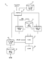
- FIG. 1 is a diagram showing a configuration example of a rolling system and a process control system including an abnormality detection device that detects an abnormality in the rolling system;
- FIG. It is a figure which shows the structural example of the abnormality detection apparatus concerning one Embodiment.
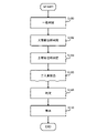
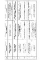
- 4 is a flow chart showing an operation example of the abnormality detection device according to the embodiment; It is a figure which enumerates and shows the specific example of the process which an abnormality detection apparatus detects abnormality, the equipment deterioration which affects, and the operation which an operator intervenes manually. It is a figure which enumerates and shows the specific example of the process which an abnormality detection apparatus detects abnormality, the equipment deterioration which affects, and the operation which an operator intervenes manually.
- FIG. 1 is a diagram showing a configuration example of a rolling system and a process control system 1 including an abnormality detection device for detecting an abnormality in the rolling system.
- a process control system 1 is configured by connecting two rolling systems, a hot rolling line 2 and a cold rolling line 3, to an abnormality detection device 4 via a control network 10, respectively. Then, the raw material (rolled material) is sequentially rolled by a plurality of rolling processes.
- the control network 10 is, for example, a network such as a LAN (Local Area Network), and may be configured to include a control LAN and an information system LAN.
- LAN Local Area Network
- the hot rolling line 2 includes, for example, a heating furnace (RF: Reheating Furnace) 20, a roughing mill (RM: Roughing mill) 21, a crop shear (CS: Crop Shear) 22, a finishing mill (FM: Finishing Mills) 23, It has a cooling device (ROT: Run Out Table) 24 and a winder (DC: Down Coiler) 25 . Further, the hot rolling line 2 is equipped with sensors 26-1 to 26-4, for example, and the operator operates the first control panel 27 so that the first controller 28 controls each part of the hot rolling line 2. configured to control.
- RF Reheating Furnace
- RM roughing mill
- CS Crop Shear
- FM Finishing Mills
- DC Down Coiler
- the rough rolling mill 21 performs rough rolling on the slab output from the heating furnace 20 , and the crop shear 22 cuts the rolled material and sends it to the finishing rolling mill 23 .
- the rough rolled material is further rolled to a predetermined specification by the finishing rolling mill 23 , cooled by the cooling device 24 , and then wound by the winder 25 .
- the hot rolling line 2 includes a plurality of steps to perform predetermined treatments on the rolled material.
- the sensor 26-1 is arranged, for example, on the delivery side of the roughing mill 21, detects the rolling performance data of the rolled material rolled by the roughing mill 21, and outputs it to the first control device 28.
- the sensor 26-1 is configured so that the first control device 28 can acquire the length, thickness, width, temperature, etc. of the rolled material at each of a plurality of different positions in the rolling direction (advancing direction of the rolled material). Detect each actual value in the rolling process.
- the sensor 26-2 is arranged on the entry side of the finishing rolling mill 23, detects rolling performance data of the rolled material sent to the finishing rolling mill 23, and outputs it to the first controller 28. For example, the sensor 26-2 obtains actual values for the rolled material so that the first controller 28 can acquire the length, thickness, width, temperature, etc. of the rolled material at each of a plurality of different positions in the rolling direction. To detect.
- the sensor 26 - 3 is arranged on the delivery side of the finishing mill 23 , detects rolling performance data of the rolled material rolled by the finishing mill 23 , and outputs it to the first controller 28 .
- the sensor 26-3 collects each actual value in the rolling process so that the first controller 28 can acquire the length, thickness, width, temperature, etc. of the rolled material at each of a plurality of different positions in the rolling direction. To detect.
- the sensor 26-4 is arranged on the output side of the cooling device 24, detects rolling performance data of the rolled material cooled by the cooling device 24, and outputs it to the first control device 28.
- the sensor 26-4 may be used for each actual value after the cooling process so that the first control device 28 can acquire the length, thickness, width, temperature, etc. of the rolled material at each of a plurality of different positions in the rolling direction. to detect
- the first control device 28 transmits each rolling performance data detected by the sensors 26-1 to 26-4 to the abnormality detection device 4 via the control network 10.
- the hot rolling line 2 is also provided with many other sensors (not shown), and transmits various data detected by the sensors to the abnormality detection device 4 .
- the cold rolling line 3 includes, for example, a payoff reel 30, an entry-side shear 31, a welding machine 32, a looper 33, a rolling mill 34, an exit-side shear 35, a tension reel 36, a plurality of sensors 37, a second operation panel 38, and a 2 controller 39 .
- the cold rolling line 3 is configured such that the second control device 39 controls each part of the cold rolling line 3 by operating the second operation panel 38 by the operator.
- the cold rolling line 3 further rolls the rolled material rolled by the hot rolling line 2 with the tail end of the coil of the rolled material wound by the winder 25 of the hot rolling line 2 as the tip.
- the payoff reel 30 pays out the rolled material toward the entry side shear 31 with the tail end of the coil wound by the winder 25 as the leading end.
- the entry-side shear 31 and the exit-side shear 35 sandwich the material between front and rear pinch rolls (not shown) in order to straighten the leading end and trailing end of the rolled material. Cut the rolled material.
- the welder 32 has the function of connecting coils by welding and making it possible to continuously perform the rolling process for a plurality of coils.
- the looper 33 stores the rolled material and supplies the rolled material to the rolling mill 34 at a constant rate.
- the rolling mill 34 further rolls the rolled material.
- the tension reel 36 winds up the rolled material rolled by the rolling mill 34 .
- the cold rolling line 3 includes a plurality of steps to perform predetermined treatments on the rolled material.
- a plurality of sensors 37 are arranged around a plurality of stands provided in the rolling mill 34 , detect, for example, the thickness of the rolled material, and output to the second control device 39 . Further, the sensor 37 may detect each actual value in the rolling process so that the second control device 39 can acquire the length, width, temperature, etc. of the rolled material at each of a plurality of positions different in the rolling direction. .
- the second control device 39 transmits each rolling performance data detected by each sensor 37 and the like to the abnormality detection device 4 via the control network 10 .
- the cold rolling line 3 is also provided with many other sensors (not shown), and transmits various data detected by the sensors to the abnormality detection device 4 .
- the process control system 1 rolls the rolled material by the hot rolling line 2 and the cold rolling line 3 respectively, and the abnormality detection device 4 receives actual time-series data and the like in each rolling process. Further, the abnormality detection device 4 receives information indicating operations performed on the first operation panel 27 and the second operation panel 38 by the operator. In other words, the abnormality detection device 4 collects the amount of operation performed by the operator on the hot rolling line 2 and the cold rolling line 3 .
- FIG. 2 is a diagram showing a configuration example of the abnormality detection device 4 according to one embodiment.
- the abnormality detection device 4 is, for example, a computer having a CPU, and includes a production information storage unit 40, a performance storage unit 41, an operation amount storage unit 42, a coincidence determination unit 43, a pre-process specification determination unit 44, and a post-process specification determination unit. 45 , an intervention operation amount extraction unit 46 , a determination unit 47 , and an output unit 48 .
- the production information storage unit 40 pre-stores production information (production conditions, etc.) of the rolled material in the hot rolling line 2 and the cold rolling line 3 .
- the production information is, for example, computer data set in advance including the steel type of the raw material to be fed to the hot rolling line 2 and the cold rolling line 3, the product size, and the like.
- the performance storage unit 41 stores performance time-series data transmitted by the hot rolling line 2 and the cold rolling line 3 .
- the actual time-series data is the result of each sensor detecting the rolled material processed in each process of the hot rolling line 2 and the cold rolling line 3 .
- the actual time-series data is data relating to quality accuracy of rolled material, stability of rolling phenomena, quality problems other than accuracy, and the like.
- the operation amount storage unit 42 stores information (time-series data) indicating operations (lever operation, gain adjustment, etc.) manually performed on the first operation panel 27 and the second operation panel 38 by the operator at his or her own discretion. do.
- the abnormality detection device 4 can collect the amount of operation performed by the operator on the hot rolling line 2 and the cold rolling line 3 .
- the coincidence determination unit 43 acquires information indicating a process start operation to the hot rolling line 2 or the cold rolling line 3 input by the operator via the first operation panel 27 or the second operation panel 38, and stores the production information. The production information stored by the unit 40 is read. Also, the coincidence determination unit 43 determines whether the process executed in each process by the hot rolling line 2 or the cold rolling line 3 matches the read production information.
- the coincidence determination unit 43 identifies processes to be executed by the hot rolling line 2 or the cold rolling line 3 from among the plurality of production conditions stored in the production information storage unit 40 . Then, the coincidence determination unit 43 outputs the standard specifications that should exist before a predetermined process to the pre-process specification determination unit 44 . Also, the coincidence determination unit 43 outputs the standard specifications that should exist after a predetermined process to the post-process specification determination unit 45 . In addition, the coincidence determination unit 43 outputs to the determination unit 47 an operation amount (a reference operation amount: for example, a threshold) that an operator can normally intervene in a predetermined process.
- an operation amount a reference operation amount: for example, a threshold
- the pre-process specification determination unit 44 compares the predetermined pre-process reference specification input from the coincidence determination unit 43 with the performance time-series data of the predetermined pre-process read out from the performance storage unit 41, and determines the pre-process specification. It is determined whether or not the rolled material in satisfies the predetermined specifications. In other words, the pre-process specification determining unit 44 quantifies the precision of the rolled material before a predetermined process and monitors changes. Then, the pre-process specification determination unit 44 outputs the determination result to the determination unit 47 .
- the post-process specification determination unit 45 compares the standard specifications after the predetermined process input from the coincidence determination unit 43 with the performance time-series data after the predetermined process read from the performance storage unit 41, and determines the post-process specifications. It is determined whether or not the rolled material in satisfies the predetermined specifications. That is, the post-process specification determination unit 45 quantifies the accuracy of the rolled material after a predetermined process and monitors changes. Then, the post-process specification determination section 45 outputs the determination result to the determination section 47 .
- the intervention operation amount extraction unit 46 reads information (time-series data) indicating the operations manually performed on the first operation panel 27 and the second operation panel 38 by the operator at his/her own judgment from the operation amount storage unit 42 . , the intervention operation amount indicating the operation amount manually intervened by the operator for each predetermined process in the hot rolling line 2 and the cold rolling line 3 , and output to the determination unit 47 . In other words, the intervention operation amount extraction unit 46 extracts the operator's operation amount, quantifies it, and monitors the change.
- the determination unit 47 determines that at least the post-process specification determination unit 45 satisfies the predetermined specifications, and the operation amount (intervention operation amount) extracted by the intervention operation amount extraction unit 46 is a predetermined operation amount ( If it exceeds a reference manipulated variable (for example, a threshold value), it is determined that there is an abnormality in the predetermined process. Then, the determination unit 47 outputs the determined result to the output unit 48 .
- a reference manipulated variable for example, a threshold value
- the determination unit 47 determines whether there is an abnormality based on the specification of the rolled material input via the first operation panel 27 or the second operation panel 38, or a standard (for example, a specific condition) that differs for each operator. You may This is because it is conceivable that the operation amount to be intervened differs depending on the specification of the rolled material or each operator. Moreover, the determination unit 47 may determine whether or not there is an abnormality using a non-statistical method such as clustering.
- the determination unit 47 determines whether or not the operator's operation is useful for maintaining the accuracy of the rolled material. is determined by logic and threshold.
- the output unit 48 outputs the determination result input from the determination unit 47 .
- the output unit 48 may output the determination results and process changes input from the determination unit 47 by displaying them on a display or the like, or output them by sound, light, or the like.
- the abnormality detection device 4 detects the past data, etc., based on the operation amount of the operator in the process. , it is determined that the process is abnormal.
- FIG. 3 is a flowchart showing an operation example of the abnormality detection device 4 according to one embodiment.
- the coincidence determination unit 43 selects the hot rolling line 2 or the cold rolling line 2 from among a plurality of production conditions stored in the production information storage unit 40 A process that the intermediate rolling line 3 performs in each step is specified.
- step 102 the pre-process specification determination unit 44 selects the predetermined pre-process reference specification input from the coincidence determination unit 43 and the predetermined pre-process performance time-series data read from the performance storage unit 41. By comparison, it is determined whether or not the rolled material before a predetermined process satisfies predetermined specifications.
- step 104 the post-process specification determination unit 45 selects the standard specification after the predetermined process input from the coincidence determination unit 43 and the performance time-series data after the predetermined process read from the performance storage unit 41. By comparing, it is determined whether or not the rolled material after the predetermined process satisfies the predetermined specifications.
- step 106 the intervention operation amount extraction unit 46 manipulates information (time-series data) indicating the operations manually performed on the first operation panel 27 and the second operation panel 38 by the operator's own judgment. It reads out from the quantity storage unit 42 and extracts each intervention operation amount indicating the operation amount manually intervened by the operator for each predetermined process in the hot rolling line 2 and the cold rolling line 3 .
- step 108 the determination unit 47 determines that at least the post-process specification determination unit 45 satisfies the predetermined specifications, and the operation amount (intervention operation amount) extracted by the intervention operation amount extraction unit 46 is If it exceeds a predetermined manipulated variable (reference manipulated variable: for example, threshold value), it is determined that there is an abnormality in the predetermined process.
- a predetermined manipulated variable reference manipulated variable: for example, threshold value
- the output unit 48 outputs the determination result input from the determination unit 47.
- the match determination unit 43 uses the steel grade number, thickness division number, width division number, etc. of the material as input data from a computer (not shown) of production information (steel grade, product size, etc.) Decide on a different number. At this time, all materials are assigned a layer number, and the same layer number is regarded as the same production condition.
- the pre-process specification determination unit 44 uses as input data actual time-series data of the material before the process (quality accuracy, instability of rolling phenomena, quality problems other than accuracy, etc.), and determines the amount of bending of the material on the delivery side of rough rolling. Quantify and monitor changes in the amount of bending of the material on the delivery side of rough rolling. As a monitoring method, the pre-process specification determination unit 44 uses, for example, a method of determining data exceeding a threshold value of 1 ⁇ based on an Xs control chart as abnormal.
- the post-process specification judging section 45 uses actual time-series data of the material after the process (quality accuracy, instability of rolling phenomena, quality problems other than accuracy, etc.) as input data, and determines the amount of bending of the material on the delivery side of the finishing rolling. Quantify and monitor changes in the amount of bending of the material on the delivery side of the finishing rolling. As a monitoring method, the post-process specification determination unit 45 uses, for example, a method of determining data exceeding a threshold value of 1 ⁇ based on an Xs control chart as being abnormal.
- the intervention operation amount extracting unit 46 uses the time-series data of the operator's operation amount (lever, gain, etc.) as input data, extracts and quantifies the operation amount of the gap leveling by the operator for the finish rolling process, and monitors the change in the operation amount. do.
- the intervention manipulated variable extracting unit 46 uses, for example, a method of judging data exceeding a threshold value of 2 ⁇ based on an Xs control chart as abnormal.
- the determination unit 47 determines the presence or absence of process changes in finish rolling or rough rolling and abnormalities in the process as follows.
- the process changes include left-right imbalance of the gap caused by the rolls, left-right imbalance of the gap caused by the screw down device, and the like.
- the determination unit 47 determines the correlation between the operator's operation amount and the post-process material accuracy using logic and threshold values, and detects changes in the process.
- the determination unit 47 determines that the amount of bending of the material on the rough output side is normal with no change, and that the amount of bending of the material on the finishing output side is normal with no change, and that the operator's If the manipulated variable changes significantly, it may be determined that the operation has absorbed the process change.
- the determination unit 47 determines that there is a change in the amount of bending of the material on the rough output side, there is no change in the amount of bending of the material on the finishing output side, and the accuracy is normal, and the operation amount of the operator changes greatly. If so, it may be determined that a change has occurred in both the current process and the previous process, or either one of them, and that the operation has absorbed the process change.
- the determination unit 47 performs the finish rolling process in which the coil is rolled. It is determined that there is a possibility of process abnormality.
- the result determined by the determination unit 47 is displayed by the output unit 48, for example, on a display.
- 4 and 5 are diagrams listing specific examples of the process (controlled object) in which the abnormality detection device 4 detects an abnormality, the equipment deterioration that affects it, and the operation (intervention method) that the operator manually intervenes. .
- the operator increases the amount of intermesh when the leveler pressing pressure changes.
- the hot rolling CTC control ⁇ hot rolling> if the on/off speed of the spray valve deteriorates, the operator switches to the fixed bank setting or adjusts the valve delay speed setting to the actual situation.
- the operator adds an offset to the target thickness or performs AGC control.
- An operation is performed to add an offset to the thickness variation target (normally 0).
- loop car position control ⁇ cold rolling/process> if the loop car housing tilts or the swing mechanism fails (meandering or plate vibration increases), the operator should move the synchronous position to the short end side. Perform the operation to set so that the loop car does not go to the long end side.
- the wiper roll control ⁇ cold rolling/process> if the surface of the wiper roll (rubber roll) is deteriorated, the operator increases the pressing amount of the wiper roll.
- the operator can additionally set the offset amount so that the actual result becomes the desired tension. to perform the operation.
- the abnormality detection device 4 determines that at least the post-process specification determination unit 45 satisfies the predetermined specification, and the operation amount extracted by the intervention operation amount extraction unit 46 is a predetermined operation. Since it is determined that there is an abnormality in the predetermined process when the amount exceeds the amount, even if the material after the predetermined process of processing the material satisfies the predetermined specifications, an abnormality occurring in the predetermined process is detected. can do.
- Each function of the abnormality detection device 4 may be partially or wholly configured by hardware such as PLD (Programmable Logic Device) or FPGA (Field Programmable Gate Array), or may be executed by a processor such as a CPU. It may be configured as a program to
Landscapes
- Engineering & Computer Science (AREA)
- Mechanical Engineering (AREA)
- Physics & Mathematics (AREA)
- General Physics & Mathematics (AREA)
- Automation & Control Theory (AREA)
- Control Of Metal Rolling (AREA)
- Testing And Monitoring For Control Systems (AREA)
Abstract
Description
Claims (3)
- 素材を所定の工程により圧延する圧延システムの異常を検出する異常検出装置において、
前記所定の工程前における素材が所定の仕様を満たしているか否かを判定する工程前仕様判定部と、
前記所定の工程後における素材が所定の仕様を満たしているか否かを判定する工程後仕様判定部と、
前記所定の工程に対してオペレータが介入した操作量を抽出する介入操作量抽出部と、
少なくとも前記工程後仕様判定部が所定の仕様を満たしていると判定し、かつ、前記介入操作量抽出部が抽出した操作量が予め定められた操作量を超えている場合に、前記所定の工程に異常があったと判定する判定部と、
前記判定部が判定した結果を出力する出力部と
を有することを特徴とする異常検出装置。 - 前記判定部は、
素材の仕様、又はオペレータごとに異なる基準により異常があったか否かを判定すること
を特徴とする請求項1に記載の異常検出装置。 - 前記判定部は、
非統計手法を用いて異常があったか否かを判定すること
を特徴とする請求項1又は2に記載の異常検出装置。
Priority Applications (4)
| Application Number | Priority Date | Filing Date | Title |
|---|---|---|---|
| JP2022506813A JP7156569B1 (ja) | 2021-07-13 | 2021-07-13 | 異常検出装置 |
| PCT/JP2021/026347 WO2023286175A1 (ja) | 2021-07-13 | 2021-07-13 | 異常検出装置 |
| CN202180060937.6A CN116324654B (zh) | 2021-07-13 | 2021-07-13 | 异常检测装置 |
| TW111113280A TWI830189B (zh) | 2021-07-13 | 2022-04-07 | 異常檢測裝置 |
Applications Claiming Priority (1)
| Application Number | Priority Date | Filing Date | Title |
|---|---|---|---|
| PCT/JP2021/026347 WO2023286175A1 (ja) | 2021-07-13 | 2021-07-13 | 異常検出装置 |
Publications (1)
| Publication Number | Publication Date |
|---|---|
| WO2023286175A1 true WO2023286175A1 (ja) | 2023-01-19 |
Family
ID=83688443
Family Applications (1)
| Application Number | Title | Priority Date | Filing Date |
|---|---|---|---|
| PCT/JP2021/026347 Ceased WO2023286175A1 (ja) | 2021-07-13 | 2021-07-13 | 異常検出装置 |
Country Status (4)
| Country | Link |
|---|---|
| JP (1) | JP7156569B1 (ja) |
| CN (1) | CN116324654B (ja) |
| TW (1) | TWI830189B (ja) |
| WO (1) | WO2023286175A1 (ja) |
Families Citing this family (1)
| Publication number | Priority date | Publication date | Assignee | Title |
|---|---|---|---|---|
| JP7156569B1 (ja) * | 2021-07-13 | 2022-10-19 | 東芝三菱電機産業システム株式会社 | 異常検出装置 |
Citations (3)
| Publication number | Priority date | Publication date | Assignee | Title |
|---|---|---|---|---|
| JPH11347614A (ja) * | 1998-06-05 | 1999-12-21 | Mitsubishi Electric Corp | 異常診断装置及び異常診断方法 |
| JP2004167604A (ja) * | 2002-11-20 | 2004-06-17 | Posco Corp Ltd | 仕上圧延異常診断装置及び方法 |
| JP2019181483A (ja) * | 2018-04-03 | 2019-10-24 | Jfeスチール株式会社 | 熱間仕上圧延の圧延制御方法および圧延制御装置 |
Family Cites Families (12)
| Publication number | Priority date | Publication date | Assignee | Title |
|---|---|---|---|---|
| KR100919423B1 (ko) * | 2002-11-20 | 2009-09-29 | 주식회사 포스코 | 사상 압연 이상 진단 장치 및 방법 |
| JP2009054843A (ja) * | 2007-08-28 | 2009-03-12 | Omron Corp | プロセス異常検出装置および方法並びにプログラム |
| JP6003718B2 (ja) * | 2012-03-06 | 2016-10-05 | Jfeスチール株式会社 | 異常監視システムおよび異常監視方法 |
| WO2017061028A1 (ja) * | 2015-10-09 | 2017-04-13 | 株式会社日立製作所 | 異常検知装置 |
| JP6374372B2 (ja) * | 2015-11-27 | 2018-08-15 | 株式会社アドヴィックス | 異常診断装置 |
| JP6791261B2 (ja) * | 2016-11-28 | 2020-11-25 | 東芝三菱電機産業システム株式会社 | 圧延設備の異常診断の方法及び装置 |
| JP2019056447A (ja) * | 2017-09-22 | 2019-04-11 | Thk株式会社 | 転がり案内装置の状態診断方法 |
| JP7031512B2 (ja) * | 2018-06-25 | 2022-03-08 | 東芝三菱電機産業システム株式会社 | 鉄鋼プラント用監視作業支援システム |
| JP7057252B2 (ja) * | 2018-08-08 | 2022-04-19 | Dmg森精機株式会社 | 異常状態判定システム |
| JP2020095617A (ja) * | 2018-12-14 | 2020-06-18 | コニカミノルタ株式会社 | 安全管理支援システム、および制御プログラム |
| JP2021023941A (ja) * | 2019-07-31 | 2021-02-22 | 東芝三菱電機産業システム株式会社 | 操作介入量評価装置 |
| JP7156569B1 (ja) * | 2021-07-13 | 2022-10-19 | 東芝三菱電機産業システム株式会社 | 異常検出装置 |
-
2021
- 2021-07-13 JP JP2022506813A patent/JP7156569B1/ja active Active
- 2021-07-13 CN CN202180060937.6A patent/CN116324654B/zh active Active
- 2021-07-13 WO PCT/JP2021/026347 patent/WO2023286175A1/ja not_active Ceased
-
2022
- 2022-04-07 TW TW111113280A patent/TWI830189B/zh active
Patent Citations (3)
| Publication number | Priority date | Publication date | Assignee | Title |
|---|---|---|---|---|
| JPH11347614A (ja) * | 1998-06-05 | 1999-12-21 | Mitsubishi Electric Corp | 異常診断装置及び異常診断方法 |
| JP2004167604A (ja) * | 2002-11-20 | 2004-06-17 | Posco Corp Ltd | 仕上圧延異常診断装置及び方法 |
| JP2019181483A (ja) * | 2018-04-03 | 2019-10-24 | Jfeスチール株式会社 | 熱間仕上圧延の圧延制御方法および圧延制御装置 |
Also Published As
| Publication number | Publication date |
|---|---|
| CN116324654A (zh) | 2023-06-23 |
| JP7156569B1 (ja) | 2022-10-19 |
| CN116324654B (zh) | 2026-04-10 |
| JPWO2023286175A1 (ja) | 2023-01-19 |
| TWI830189B (zh) | 2024-01-21 |
| TW202303319A (zh) | 2023-01-16 |
Similar Documents
| Publication | Publication Date | Title |
|---|---|---|
| CN109926453A (zh) | 确定单机架可逆冷轧机升降速轧制效率系数的方法 | |
| JP7156569B1 (ja) | 異常検出装置 | |
| KR20250093609A (ko) | 마무리 압연재의 폭 예측 방법, 마무리 압연재의 폭 제어 방법, 열연 강판의 제조 방법, 및 마무리 압연재의 폭 예측 모델의 생성 방법 | |
| JP4847111B2 (ja) | 多段式圧延機及び多段式圧延機の制御方法 | |
| JP7750417B2 (ja) | タンデム圧延機の板厚スケジュール計算方法及び圧延プラント | |
| JP7517369B2 (ja) | 鋼板の板プロフィル判定方法、処置工程設定方法、製造方法、及び板プロフィル判定モデルの生成方法 | |
| JP7230880B2 (ja) | 圧延荷重予測方法、圧延方法、熱延鋼板の製造方法、及び圧延荷重予測モデルの生成方法 | |
| CN101939118B (zh) | 钢板带轧制方法及钢板制造方法 | |
| CN117881493A (zh) | 轧机的板厚控制方法以及刚性监视方法 | |
| JP2934178B2 (ja) | 熱間圧延における板厚精度予測方法 | |
| JP3709028B2 (ja) | 冷間タンデム圧延方法および冷間タンデム圧延機 | |
| JP7327675B2 (ja) | データ収集装置 | |
| WO2011004454A1 (ja) | 操業支援装置、操業支援方法及びプログラム | |
| CN113578975A (zh) | 一种酸轧轧机紧急变规格的方法 | |
| JP2000263113A (ja) | 圧延機における異常圧延状態修正方法および装置 | |
| CN118568962B (zh) | 一种槽钢轧辊孔型磨损量在线预测方法及系统 | |
| EP4516419A1 (en) | Method for setting rolling condition for cold rolling mill, cold rolling method, method for manufacturing steel sheet, device for setting rolling condition for cold rolling mill, and cold rolling mill | |
| KR100510107B1 (ko) | 열간 압연 강판 제조시 강판의 폭 압연 방법 | |
| JP2018158365A (ja) | 熱間圧延方法及び熱間圧延装置 | |
| EP4647188A1 (en) | Cold rolling condition-setting method, cold rolling method, cold rolled steel sheet manufacturing method, cold rolling condition-calculating device, and cold rolling mill | |
| TWI877839B (zh) | 鋼板的冷軋方法、冷軋鋼板的製造方法及冷軋鋼板的製造設備 | |
| JP7626256B2 (ja) | 粗圧延材の幅制御方法及び熱延鋼板の製造方法 | |
| US20240399434A1 (en) | Strip thickness control device for hot rolling mill | |
| Degtev et al. | Stabilization of Strip Thickness at Nonstationary Stages of Cold Rolling in Multistand Rolling Mill for Shortening End Sections of Metal Strips with Thickness Outside Tolerance Space | |
| JP2018140400A (ja) | 熱間仕上圧延異常時の被圧延材処理方法 |
Legal Events
| Date | Code | Title | Description |
|---|---|---|---|
| ENP | Entry into the national phase |
Ref document number: 2022506813 Country of ref document: JP Kind code of ref document: A |
|
| WWE | Wipo information: entry into national phase |
Ref document number: 202317002869 Country of ref document: IN |
|
| 121 | Ep: the epo has been informed by wipo that ep was designated in this application |
Ref document number: 21950116 Country of ref document: EP Kind code of ref document: A1 |
|
| NENP | Non-entry into the national phase |
Ref country code: DE |
|
| 122 | Ep: pct application non-entry in european phase |
Ref document number: 21950116 Country of ref document: EP Kind code of ref document: A1 |