WO2023282097A1 - 物体検出装置 - Google Patents
物体検出装置 Download PDFInfo
- Publication number
- WO2023282097A1 WO2023282097A1 PCT/JP2022/025401 JP2022025401W WO2023282097A1 WO 2023282097 A1 WO2023282097 A1 WO 2023282097A1 JP 2022025401 W JP2022025401 W JP 2022025401W WO 2023282097 A1 WO2023282097 A1 WO 2023282097A1
- Authority
- WO
- WIPO (PCT)
- Prior art keywords
- transmission
- deviation
- detection device
- wave
- echo information
- Prior art date
- Legal status (The legal status is an assumption and is not a legal conclusion. Google has not performed a legal analysis and makes no representation as to the accuracy of the status listed.)
- Ceased
Links
Images




Classifications
-
- G—PHYSICS
- G01—MEASURING; TESTING
- G01S—RADIO DIRECTION-FINDING; RADIO NAVIGATION; DETERMINING DISTANCE OR VELOCITY BY USE OF RADIO WAVES; LOCATING OR PRESENCE-DETECTING BY USE OF THE REFLECTION OR RERADIATION OF RADIO WAVES; ANALOGOUS ARRANGEMENTS USING OTHER WAVES
- G01S15/00—Systems using the reflection or reradiation of acoustic waves, e.g. sonar systems
- G01S15/88—Sonar systems specially adapted for specific applications
- G01S15/93—Sonar systems specially adapted for specific applications for anti-collision purposes
- G01S15/931—Sonar systems specially adapted for specific applications for anti-collision purposes of land vehicles
-
- G—PHYSICS
- G01—MEASURING; TESTING
- G01S—RADIO DIRECTION-FINDING; RADIO NAVIGATION; DETERMINING DISTANCE OR VELOCITY BY USE OF RADIO WAVES; LOCATING OR PRESENCE-DETECTING BY USE OF THE REFLECTION OR RERADIATION OF RADIO WAVES; ANALOGOUS ARRANGEMENTS USING OTHER WAVES
- G01S7/00—Details of systems according to groups G01S13/00, G01S15/00, G01S17/00
- G01S7/52—Details of systems according to groups G01S13/00, G01S15/00, G01S17/00 of systems according to group G01S15/00
- G01S7/52004—Means for monitoring or calibrating
-
- G—PHYSICS
- G01—MEASURING; TESTING
- G01S—RADIO DIRECTION-FINDING; RADIO NAVIGATION; DETERMINING DISTANCE OR VELOCITY BY USE OF RADIO WAVES; LOCATING OR PRESENCE-DETECTING BY USE OF THE REFLECTION OR RERADIATION OF RADIO WAVES; ANALOGOUS ARRANGEMENTS USING OTHER WAVES
- G01S7/00—Details of systems according to groups G01S13/00, G01S15/00, G01S17/00
- G01S7/52—Details of systems according to groups G01S13/00, G01S15/00, G01S17/00 of systems according to group G01S15/00
- G01S7/523—Details of pulse systems
- G01S7/526—Receivers
- G01S7/527—Extracting wanted echo signals
-
- G—PHYSICS
- G01—MEASURING; TESTING
- G01S—RADIO DIRECTION-FINDING; RADIO NAVIGATION; DETERMINING DISTANCE OR VELOCITY BY USE OF RADIO WAVES; LOCATING OR PRESENCE-DETECTING BY USE OF THE REFLECTION OR RERADIATION OF RADIO WAVES; ANALOGOUS ARRANGEMENTS USING OTHER WAVES
- G01S7/00—Details of systems according to groups G01S13/00, G01S15/00, G01S17/00
- G01S7/52—Details of systems according to groups G01S13/00, G01S15/00, G01S17/00 of systems according to group G01S15/00
- G01S7/539—Details of systems according to groups G01S13/00, G01S15/00, G01S17/00 of systems according to group G01S15/00 using analysis of echo signal for target characterisation; Target signature; Target cross-section
-
- G—PHYSICS
- G01—MEASURING; TESTING
- G01S—RADIO DIRECTION-FINDING; RADIO NAVIGATION; DETERMINING DISTANCE OR VELOCITY BY USE OF RADIO WAVES; LOCATING OR PRESENCE-DETECTING BY USE OF THE REFLECTION OR RERADIATION OF RADIO WAVES; ANALOGOUS ARRANGEMENTS USING OTHER WAVES
- G01S13/00—Systems using the reflection or reradiation of radio waves, e.g. radar systems; Analogous systems using reflection or reradiation of waves whose nature or wavelength is irrelevant or unspecified
- G01S13/88—Radar or analogous systems specially adapted for specific applications
- G01S13/93—Radar or analogous systems specially adapted for specific applications for anti-collision purposes
- G01S13/931—Radar or analogous systems specially adapted for specific applications for anti-collision purposes of land vehicles
-
- G—PHYSICS
- G01—MEASURING; TESTING
- G01S—RADIO DIRECTION-FINDING; RADIO NAVIGATION; DETERMINING DISTANCE OR VELOCITY BY USE OF RADIO WAVES; LOCATING OR PRESENCE-DETECTING BY USE OF THE REFLECTION OR RERADIATION OF RADIO WAVES; ANALOGOUS ARRANGEMENTS USING OTHER WAVES
- G01S15/00—Systems using the reflection or reradiation of acoustic waves, e.g. sonar systems
- G01S15/88—Sonar systems specially adapted for specific applications
- G01S15/93—Sonar systems specially adapted for specific applications for anti-collision purposes
- G01S15/931—Sonar systems specially adapted for specific applications for anti-collision purposes of land vehicles
- G01S2015/937—Sonar systems specially adapted for specific applications for anti-collision purposes of land vehicles sensor installation details
- G01S2015/938—Sonar systems specially adapted for specific applications for anti-collision purposes of land vehicles sensor installation details in the bumper area
Definitions
- the present disclosure relates to an object detection device.
- a transmission wave such as an ultrasonic wave is transmitted from the vehicle, and a reception wave (reflected wave) generated by the reflection of the transmission wave from the object is received, thereby detecting objects existing around the vehicle.
- An object detection device is utilized. For example, in a device for detecting a collision of an object with a vehicle, a configuration using a combination of an ultrasonic sensor and an impact sensor is disclosed (Patent Document 1).
- One of the problems to be solved by the present disclosure is to provide an object detection device capable of detecting the deviation of the transmitter/receiver.
- An object detection device as an example of the present disclosure is an object detection device that is mounted on a mobile body and detects an object existing around the mobile body, transmits a transmission wave, and reflects the transmission wave from the object. At a predetermined mounting position of the transmitter/receiver based on the transmitter/receiver that receives the received wave generated by the and a deviation detection unit that detects a deviation from a certain normal position.
- the deviation detection unit may detect deviation when an impact on the moving body is detected.
- the deviation detection unit may detect deviation when the moving body shifts from the stopped state to the driven state.
- the reference echo information may be echo information acquired when the transmitting/receiving unit is at a regular position.
- the reference echo information may include road surface information based on waves received from the road surface.
- the deviation of the transmitting/receiving unit can be accurately detected by using the road surface information corresponding to the normal position.
- FIG. 1 is a top view showing an example of the configuration of a vehicle according to a first embodiment
- FIG. FIG. 2 is a block diagram of an example of a hardware configuration of the vehicle control system according to the embodiment
- 3 is a block diagram illustrating an example of a functional configuration of the object detection device according to the embodiment
- FIG. FIG. 4 is a diagram for explaining an outline of an obstacle detection method using TOF.
- FIG. 5 is a diagram illustrating an example of reference echo information according to the embodiment
- FIG. 6 is a diagram showing a comparison example between echo information after occurrence of deviation and reference echo information in the embodiment.
- FIG. 7 is a flowchart illustrating an example of processing when detecting a deviation of the transmitting/receiving unit in the object detection device according to the embodiment;
- FIG. 1 is a top view showing an example of the configuration of the vehicle 1 according to the embodiment.
- a vehicle 1 is an example of a moving body on which the object detection device according to the present embodiment is mounted.
- the object detection apparatus according to the present embodiment transmits a transmission wave from the vehicle 1 and receives a received wave (reflected wave) generated by the reflection of the transmitted wave from an object, thereby obtaining a TOF (Time Of Flight). , Doppler shift, etc., to detect objects (other vehicles, structures, pedestrians, etc.) existing around the vehicle 1.
- TOF Time Of Flight
- the object detection device includes a plurality of transmission/reception units 21A to 21H (hereinafter abbreviated as transmission/reception unit 21 when there is no need to distinguish between the plurality of transmission/reception units 21A to 21H).
- Each transmitting/receiving unit 21 is installed in the vehicle body 2 as the exterior of the vehicle 1, transmits an ultrasonic wave (an example of a transmission wave) toward the outside of the vehicle body 2, and receives a reflected wave from an object existing outside the vehicle body 2. Received as received waves.
- four transmitting/receiving units 21A to 21D are arranged at the front end of the vehicle body 2
- four transmitting/receiving units 21E to 21H are arranged at the rear end.
- the number and installation positions of the transmitting/receiving units 21 are not limited to this example.
- FIG. 2 is a block diagram showing an example of the hardware configuration of the vehicle control system 50 according to the embodiment.
- the vehicle control system 50 performs processing for controlling the vehicle 1 based on information output from the object detection device 200 .
- a vehicle control system 50 according to this embodiment includes an ECU 100 and an object detection device 200 .
- the object detection device 200 includes a plurality of transmission/reception units 21 and a control unit 220.
- Each transmission/reception unit 21 includes a transducer 211 configured using a piezoelectric element or the like, an amplifier, and the like, and realizes transmission and reception of ultrasonic waves by vibration of the transducer 211 .
- each transmitting/receiving unit 21 transmits an ultrasonic wave generated in accordance with the vibration of the transducer 211 as a transmission wave, and the transmission wave is a reflected wave ( Vibration of the vibrator 211 caused by the received wave) is detected.
- the vibration of the vibrator 211 is converted into an electric signal, and based on the electric signal, TOF corresponding to the distance from the transmitting/receiving unit 21 to the obstacle O, Doppler shift information corresponding to the relative speed of the obstacle O, etc. can be obtained. .
- FIG. 2 illustrates a configuration in which both transmission of transmission waves and reception of reception waves are performed using a single transducer 211, but the configuration of the transmission/reception unit 21 is similar to this. It is not limited. For example, a configuration in which a transmitting side and a receiving side are separated, such as a configuration in which a transducer for transmitting a transmission wave and a transducer for receiving a received wave are separately provided, may be employed.
- the control unit 220 includes an input/output device 221 , a storage device 222 and a processor 223 .
- the input/output device 221 is an interface device that enables transmission and reception of information between the control unit 220 and the outside (the transmission/reception unit 21, the ECU 100, etc.).
- the storage device 222 includes main storage devices such as ROM (Read Only Memory) and RAM (Random Access Memory), and auxiliary storage devices such as HDD (Hard Disk Drive) and SSD (Solid State Drive).
- the processor 223 is an integrated circuit that executes various processes for realizing the functions of the control unit 220. For example, a CPU (Central Processing Unit) that operates according to a program, an ASIC (Application Specific Integrated Circuit) designed for a specific application. and the like.
- the processor 223 reads and executes programs stored in the storage device 222 to perform various arithmetic processing and control processing.
- the ECU 100 is a unit that executes various processes for controlling the vehicle 1 based on various information acquired from the object detection device 200 and the like.
- the ECU 100 has an input/output device 110 , a storage device 120 and a processor 130 .
- the input/output device 110 is an interface device that enables transmission and reception of information between the ECU 100 and external mechanisms (object detection device 200, drive mechanism, braking mechanism, steering mechanism, transmission mechanism, in-vehicle display, speaker, various sensors, etc.).
- the storage device 120 includes main storage devices such as ROM and RAM, and auxiliary storage devices such as HDD and SSD.
- the processor 130 is an integrated circuit that executes various processes for realizing the functions of the ECU 100, and can be configured using, for example, a CPU, an ASIC, or the like.
- the processor 130 reads programs stored in the storage device 120 and executes various arithmetic processing and control processing.
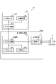
- FIG. 3 is a block diagram showing an example of the functional configuration of the object detection device 200 according to the embodiment.
- the object detection device 200 according to this embodiment has a signal processing section 301 , an obstacle detection section 302 , a deviation detection section 303 and an output section 304 .
- These functional components 301 to 304 can be realized, for example, by cooperation of hardware components of the object detection device 200 illustrated in FIG. 2 and software components such as firmware and programs.
- the signal processing unit 301 processes the signal acquired by the transmitting/receiving unit 21 and generates various data.
- the signal processing unit 301 performs, for example, amplification processing, filtering processing, envelope processing, etc. on the electrical signal corresponding to the vibration of the transducer 211, and measures the intensity (signal level) of the ultrasonic waves transmitted and received by the transmission/reception unit 21 over time. Generates echo information that indicates changes. Based on the echo information, a TOF corresponding to an object existing around the vehicle 1 can be detected, and the distance from the vehicle 1 (transmitting/receiving unit 21) to the object can be calculated.
- the obstacle detection unit 302 detects obstacles O (for example, other vehicles, structures, pedestrians, etc.) existing around the vehicle 1 based on the echo information and the like generated by the signal processing unit 301, and detects the obstacles. Generate obstacle information for O.
- the obstacle information may include, for example, the distance from the vehicle 1 to the obstacle O, the relative speed of the obstacle O, the moving direction of the obstacle O, the type of the obstacle O, and the like.
- the deviation detection unit 303 Based on the echo information generated by the signal processing unit 301 and the reference echo information prepared in advance, the deviation detection unit 303 detects the movement of the transmission/reception unit 21 from the predetermined normal position where the transmission/reception unit 21 is mounted. A deviation is detected, and deviation information relating to the deviation of the transmitting/receiving unit 21 is generated.
- the reference echo information is echo information acquired when the transmitting/receiving section 21 is at a regular position, and preferably includes road surface information based on received waves from the road surface RS.
- the road surface information may include, for example, the TOF indicating the distance from the transmitting/receiving unit 21 at the normal position to the road surface, the strength of the received wave corresponding to the TOF, and the like.
- the reference echo information may be stored in advance in the storage devices 222, 120, etc. in FIG.
- the deviation detection unit 303 executes processing for detecting deviation of the transmission/reception unit 21 and generates deviation information when a predetermined start condition is satisfied.
- the start condition may be, for example, when an impact to the vehicle is detected, when the vehicle 1 transitions from a stopped state to a driving state, and the like.
- Such a function of the displacement detection unit 303 can detect displacement of the transmission/reception unit 21 caused by contact of an object with the vehicle 1, vibration of the vehicle 1, or the like.
- the output unit 304 outputs the obstacle information generated by the obstacle detection unit 302 and the deviation information generated by the deviation detection unit 303 to a predetermined mechanism (ECU 100, etc.).
- the obstacle information and deviation information output from the output unit 304 can be used for various controls such as danger avoidance control of the vehicle 1 .
- FIG. 4 is a diagram for explaining the outline of the obstacle detection method using TOF.
- FIG. 4 exemplifies an envelope L11 (an example of echo information) indicating a temporal change in the intensity of the ultrasonic waves transmitted and received by the transmitter/receiver 21 .
- the horizontal axis corresponds to time (TOF)
- the vertical axis corresponds to the intensity of ultrasonic waves transmitted and received by the transmitting/receiving section 21 (magnitude of vibration of transducer 211).
- An envelope L11 indicates the change over time of the strength indicating the magnitude of vibration of the vibrator 211 .
- the oscillator 211 is driven and oscillated for the time Ta from the timing t0, and the transmission of the transmission wave is completed at the timing t1.
- the vibration of the vibrator 211 due to inertia continues while attenuating. Therefore, in the graph shown in FIG. 4, the time Tb corresponds to the so-called reverberation time.
- the envelope L11 reaches a peak when the magnitude of vibration of the vibrator 211 is equal to or greater than the detection threshold Ith at timing t4, which is the time Tp after the timing t0 when transmission of the transmission wave is started.
- This detection threshold value Ith is determined whether the vibration of the oscillator 211 is caused by receiving a received wave from an obstacle O (another vehicle, a structure, a pedestrian, etc.) or an object other than the obstacle O (for example, the road surface RS etc.).
- the detection threshold Ith is shown here as a constant value, the detection threshold Ith may be a variable value that changes according to the situation.
- a vibration having a peak equal to or greater than the detection threshold Ith can be regarded as being caused by the reception of the received wave from the obstacle O.
- the envelope L11 in this example indicates that the vibration of the vibrator 211 is attenuated after timing t4. Therefore, the timing t4 corresponds to the timing when the reception of the received wave from the obstacle O is completed, in other words, the timing when the last transmitted wave at the timing t1 returns as the received wave.
- timing t3 which is the starting point of the peak at timing t4 is the timing at which reception of the received wave from the obstacle O starts. corresponds to the timing of returning as Therefore, the time ⁇ T between the timing t3 and the timing t4 is equal to the time Ta as the transmission time of the transmission wave.
- the timing t0 when the transmission wave starts to be transmitted and the reception wave starts to be received It is necessary to obtain the time Tf between timing t3.
- This time Tf is obtained by subtracting the time ⁇ T equal to the time Ta as the transmission time of the transmission wave from the time Tp as the difference between the timing t0 and the timing t4 when the intensity of the received wave exceeds the detection threshold value Ith and peaks. can ask.
- the timing t0 when the transmission wave starts to be transmitted can be easily identified as the timing when the object detection device 200 starts operating, and the time Ta as the transmission time of the transmission wave is predetermined by setting or the like. Therefore, the distance from the transmission/reception source to the obstacle O can be obtained by specifying the timing t4 at which the intensity of the received wave reaches a peak equal to or greater than the detection threshold value Ith.
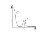
- FIG. 5 is a diagram showing an example of reference echo information Lc according to the embodiment.
- the reference echo information Lc according to the present embodiment is echo information acquired when the transmitting/receiving unit 21 is at the normal position, and corresponds to the received wave from the road surface RS received when the transmitting/receiving unit 21 is at the normal position.
- FIG. 6 is a diagram showing a comparison example between the echo information L and the reference echo information Lc after occurrence of deviation in the embodiment. If the transmission/reception unit 21 deviates due to an impact or the like on the vehicle 1, an error occurs between the peak P in the echo information L and the reference peak Pc, as illustrated in FIG. For example, when at least one of the error between the time T of the peak P and the reference time Tc and the error between the intensity I of the peak P and the reference intensity Ic is equal to or greater than a predetermined value, it is determined that the transmission/reception unit 21 has deviated. I can judge.
- the method of comparing echo information and reference echo information is not limited to the above.
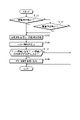
- FIG. 7 is a flowchart showing an example of processing when detecting deviation of the transmitter/receiver 21 in the object detection device 200 according to the embodiment.
- the deviation detection unit 303 determines whether or not it is time to start driving the vehicle 1 from a stopped state to a driving state (S101). If it is time to start driving (S101: Yes), the transmitter/receiver 21 transmits a transmission wave and receives a reception wave (S103), and the signal processing unit 301 generates echo information L (S104).
- the deviation detection unit 303 determines whether or not an impact to the vehicle 1 is detected based on impact information (for example, output of an acceleration sensor) acquired from the ECU 100 or the like ( S102). If the impact on the vehicle 1 is detected (S102: Yes), steps S103 and S104 are executed, and if the impact on the vehicle 1 is not detected (S102: No), this routine ends.
- impact information for example, output of an acceleration sensor
- the deviation detection unit 303 compares the echo information L and the reference echo information Lc to determine the difference between the echo information L and the reference echo information Lc (for example, the peak P and the reference peak Pc). ) is equal to or greater than a predetermined value (S105). If the error between the echo information L and the reference echo information Lc is greater than or equal to a predetermined value (S105: Yes), the deviation detection unit 303 generates deviation information indicating that a deviation has occurred in the transmission/reception unit 21, and the output unit 304 The deviation information is output to the ECU 100 and the like (S106). If the error between the echo information L and the reference echo information Lc is less than the predetermined value (S105: No), this routine ends.
- a program that causes a computer for example, the processor 223 of the control unit 220, the processor 130 of the ECU 100, etc.
- a computer for example, the processor 223 of the control unit 220, the processor 130 of the ECU 100, etc.
- the processing for realizing various functions in the above-described embodiment can be downloaded as an installable or executable file on a CD (Compact Disc)-ROM, flexible disk (FD), CD-R (Recordable), DVD (Digital Versatile Disk), or other computer-readable recording medium, which can be recorded and provided.
- the program may be provided or distributed via a network such as the Internet.
Landscapes
- Engineering & Computer Science (AREA)
- Radar, Positioning & Navigation (AREA)
- Remote Sensing (AREA)
- Physics & Mathematics (AREA)
- Computer Networks & Wireless Communication (AREA)
- General Physics & Mathematics (AREA)
- Acoustics & Sound (AREA)
- Measurement Of Velocity Or Position Using Acoustic Or Ultrasonic Waves (AREA)
- Traffic Control Systems (AREA)
Priority Applications (4)
| Application Number | Priority Date | Filing Date | Title |
|---|---|---|---|
| CN202280042248.7A CN117480407A (zh) | 2021-07-06 | 2022-06-24 | 物体检测装置 |
| US18/289,078 US20240230893A1 (en) | 2021-07-06 | 2022-06-24 | Object detection device |
| EP22837514.3A EP4369039A4 (en) | 2021-07-06 | 2022-06-24 | Object detection device |
| JP2023533538A JPWO2023282097A1 (https=) | 2021-07-06 | 2022-06-24 |
Applications Claiming Priority (2)
| Application Number | Priority Date | Filing Date | Title |
|---|---|---|---|
| JP2021112223 | 2021-07-06 | ||
| JP2021-112223 | 2021-07-06 |
Publications (1)
| Publication Number | Publication Date |
|---|---|
| WO2023282097A1 true WO2023282097A1 (ja) | 2023-01-12 |
Family
ID=84801053
Family Applications (1)
| Application Number | Title | Priority Date | Filing Date |
|---|---|---|---|
| PCT/JP2022/025401 Ceased WO2023282097A1 (ja) | 2021-07-06 | 2022-06-24 | 物体検出装置 |
Country Status (5)
| Country | Link |
|---|---|
| US (1) | US20240230893A1 (https=) |
| EP (1) | EP4369039A4 (https=) |
| JP (1) | JPWO2023282097A1 (https=) |
| CN (1) | CN117480407A (https=) |
| WO (1) | WO2023282097A1 (https=) |
Citations (6)
| Publication number | Priority date | Publication date | Assignee | Title |
|---|---|---|---|---|
| JP2014133478A (ja) | 2013-01-10 | 2014-07-24 | Denso Corp | 車両情報記録装置 |
| WO2015118804A1 (ja) * | 2014-02-05 | 2015-08-13 | パナソニックIpマネジメント株式会社 | 物体検知装置 |
| JP2017207334A (ja) * | 2016-05-17 | 2017-11-24 | 本田技研工業株式会社 | 移動体 |
| JP2018072236A (ja) * | 2016-11-01 | 2018-05-10 | 株式会社デンソー | 異常検出装置 |
| DE102019119586A1 (de) * | 2019-07-19 | 2021-01-21 | Valeo Schalter Und Sensoren Gmbh | Ausrichtungs- und Einbaupositionserkennung von Ultraschallsensoren anhand einer statistischen Analyse von Bodenreflexionen |
| US20210173063A1 (en) * | 2017-12-01 | 2021-06-10 | Volkswagen Aktiengesellschaft | Method for checking a distance measuring device having an ultrasonic sensor |
Family Cites Families (3)
| Publication number | Priority date | Publication date | Assignee | Title |
|---|---|---|---|---|
| JP2002148347A (ja) * | 2000-08-31 | 2002-05-22 | Denso Corp | 車両用障害物検知装置 |
| WO2013161834A1 (ja) * | 2012-04-24 | 2013-10-31 | 非破壊検査株式会社 | 積層体の剥離検査方法及び剥離検査装置 |
| JP2017167096A (ja) * | 2016-03-18 | 2017-09-21 | パナソニックIpマネジメント株式会社 | 取り付け状態判定装置および取り付け状態判定方法 |
-
2022
- 2022-06-24 JP JP2023533538A patent/JPWO2023282097A1/ja active Pending
- 2022-06-24 US US18/289,078 patent/US20240230893A1/en active Pending
- 2022-06-24 CN CN202280042248.7A patent/CN117480407A/zh active Pending
- 2022-06-24 WO PCT/JP2022/025401 patent/WO2023282097A1/ja not_active Ceased
- 2022-06-24 EP EP22837514.3A patent/EP4369039A4/en not_active Withdrawn
Patent Citations (6)
| Publication number | Priority date | Publication date | Assignee | Title |
|---|---|---|---|---|
| JP2014133478A (ja) | 2013-01-10 | 2014-07-24 | Denso Corp | 車両情報記録装置 |
| WO2015118804A1 (ja) * | 2014-02-05 | 2015-08-13 | パナソニックIpマネジメント株式会社 | 物体検知装置 |
| JP2017207334A (ja) * | 2016-05-17 | 2017-11-24 | 本田技研工業株式会社 | 移動体 |
| JP2018072236A (ja) * | 2016-11-01 | 2018-05-10 | 株式会社デンソー | 異常検出装置 |
| US20210173063A1 (en) * | 2017-12-01 | 2021-06-10 | Volkswagen Aktiengesellschaft | Method for checking a distance measuring device having an ultrasonic sensor |
| DE102019119586A1 (de) * | 2019-07-19 | 2021-01-21 | Valeo Schalter Und Sensoren Gmbh | Ausrichtungs- und Einbaupositionserkennung von Ultraschallsensoren anhand einer statistischen Analyse von Bodenreflexionen |
Non-Patent Citations (1)
| Title |
|---|
| See also references of EP4369039A4 |
Also Published As
| Publication number | Publication date |
|---|---|
| CN117480407A (zh) | 2024-01-30 |
| EP4369039A1 (en) | 2024-05-15 |
| EP4369039A4 (en) | 2024-10-30 |
| US20240230893A1 (en) | 2024-07-11 |
| JPWO2023282097A1 (https=) | 2023-01-12 |
Similar Documents
| Publication | Publication Date | Title |
|---|---|---|
| US11999353B2 (en) | Detection device for detecting road surface information related to movable body and control thereof | |
| WO2023282097A1 (ja) | 物体検出装置 | |
| JP7460020B2 (ja) | 物体検出装置 | |
| WO2022239470A1 (ja) | 物体検出装置 | |
| WO2023189807A1 (ja) | 物体検出装置 | |
| JP7721906B2 (ja) | 物体検出装置及び移動体制御装置 | |
| US12517246B2 (en) | Object detection device | |
| JP7563317B2 (ja) | 物体検出装置、物体検出方法、及びプログラム | |
| US12618956B2 (en) | Object detection device and object detection method | |
| JP2025062323A (ja) | 物体検出装置 | |
| US20240201352A1 (en) | Object detection device | |
| US12613324B2 (en) | Object detection device, object detection method, and program | |
| JP7547853B2 (ja) | 物体検出装置 | |
| US20220291367A1 (en) | Object detection device and moving body control device | |
| JP2025121307A (ja) | 物体検出装置 | |
| WO2025169808A1 (ja) | 物体検出装置 | |
| JP2025121308A (ja) | 物体検出装置 | |
| WO2025074778A1 (ja) | 物体検出装置 | |
| WO2025163959A1 (ja) | 物体検出装置 | |
| WO2025164629A1 (ja) | 物体検出装置 |
Legal Events
| Date | Code | Title | Description |
|---|---|---|---|
| 121 | Ep: the epo has been informed by wipo that ep was designated in this application |
Ref document number: 22837514 Country of ref document: EP Kind code of ref document: A1 |
|
| WWE | Wipo information: entry into national phase |
Ref document number: 18289078 Country of ref document: US |
|
| WWE | Wipo information: entry into national phase |
Ref document number: 2023533538 Country of ref document: JP |
|
| WWE | Wipo information: entry into national phase |
Ref document number: 202280042248.7 Country of ref document: CN |
|
| WWE | Wipo information: entry into national phase |
Ref document number: 2022837514 Country of ref document: EP |
|
| NENP | Non-entry into the national phase |
Ref country code: DE |
|
| ENP | Entry into the national phase |
Ref document number: 2022837514 Country of ref document: EP Effective date: 20240206 |
|
| WWW | Wipo information: withdrawn in national office |
Ref document number: 2022837514 Country of ref document: EP |