WO2023277115A1 - 車両の後部構造 - Google Patents
車両の後部構造 Download PDFInfo
- Publication number
- WO2023277115A1 WO2023277115A1 PCT/JP2022/026148 JP2022026148W WO2023277115A1 WO 2023277115 A1 WO2023277115 A1 WO 2023277115A1 JP 2022026148 W JP2022026148 W JP 2022026148W WO 2023277115 A1 WO2023277115 A1 WO 2023277115A1
- Authority
- WO
- WIPO (PCT)
- Prior art keywords
- vehicle
- battery
- vertical wall
- wall portion
- width direction
- Prior art date
- Legal status (The legal status is an assumption and is not a legal conclusion. Google has not performed a legal analysis and makes no representation as to the accuracy of the status listed.)
- Ceased
Links
Images




Classifications
-
- B—PERFORMING OPERATIONS; TRANSPORTING
- B60—VEHICLES IN GENERAL
- B60K—ARRANGEMENT OR MOUNTING OF PROPULSION UNITS OR OF TRANSMISSIONS IN VEHICLES; ARRANGEMENT OR MOUNTING OF PLURAL DIVERSE PRIME-MOVERS IN VEHICLES; AUXILIARY DRIVES FOR VEHICLES; INSTRUMENTATION OR DASHBOARDS FOR VEHICLES; ARRANGEMENTS IN CONNECTION WITH COOLING, AIR INTAKE, GAS EXHAUST OR FUEL SUPPLY OF PROPULSION UNITS IN VEHICLES
- B60K1/00—Arrangement or mounting of electrical propulsion units
- B60K1/04—Arrangement or mounting of electrical propulsion units of the electric storage means for propulsion
-
- B—PERFORMING OPERATIONS; TRANSPORTING
- B60—VEHICLES IN GENERAL
- B60R—VEHICLES, VEHICLE FITTINGS, OR VEHICLE PARTS, NOT OTHERWISE PROVIDED FOR
- B60R16/00—Electric or fluid circuits specially adapted for vehicles and not otherwise provided for; Arrangement of elements of electric or fluid circuits specially adapted for vehicles and not otherwise provided for
- B60R16/02—Electric or fluid circuits specially adapted for vehicles and not otherwise provided for; Arrangement of elements of electric or fluid circuits specially adapted for vehicles and not otherwise provided for electric constitutive elements
- B60R16/04—Arrangement of batteries
-
- B—PERFORMING OPERATIONS; TRANSPORTING
- B60—VEHICLES IN GENERAL
- B60R—VEHICLES, VEHICLE FITTINGS, OR VEHICLE PARTS, NOT OTHERWISE PROVIDED FOR
- B60R5/00—Compartments within vehicle body primarily intended or sufficiently spacious for trunks, suit-cases, or the like
- B60R5/04—Compartments within vehicle body primarily intended or sufficiently spacious for trunks, suit-cases, or the like arranged at rear of vehicle
-
- B—PERFORMING OPERATIONS; TRANSPORTING
- B62—LAND VEHICLES FOR TRAVELLING OTHERWISE THAN ON RAILS
- B62D—MOTOR VEHICLES; TRAILERS
- B62D25/00—Superstructure or monocoque structure sub-units; Parts or details thereof not otherwise provided for
- B62D25/20—Floors or bottom sub-units
-
- H—ELECTRICITY
- H01—ELECTRIC ELEMENTS
- H01M—PROCESSES OR MEANS, e.g. BATTERIES, FOR THE DIRECT CONVERSION OF CHEMICAL ENERGY INTO ELECTRICAL ENERGY
- H01M50/00—Constructional details or processes of manufacture of the non-active parts of electrochemical cells other than fuel cells, e.g. hybrid cells
- H01M50/20—Mountings; Secondary casings or frames; Racks, modules or packs; Suspension devices; Shock absorbers; Transport or carrying devices; Holders
- H01M50/244—Secondary casings; Racks; Suspension devices; Carrying devices; Holders characterised by their mounting method
-
- H—ELECTRICITY
- H01—ELECTRIC ELEMENTS
- H01M—PROCESSES OR MEANS, e.g. BATTERIES, FOR THE DIRECT CONVERSION OF CHEMICAL ENERGY INTO ELECTRICAL ENERGY
- H01M50/00—Constructional details or processes of manufacture of the non-active parts of electrochemical cells other than fuel cells, e.g. hybrid cells
- H01M50/20—Mountings; Secondary casings or frames; Racks, modules or packs; Suspension devices; Shock absorbers; Transport or carrying devices; Holders
- H01M50/249—Mountings; Secondary casings or frames; Racks, modules or packs; Suspension devices; Shock absorbers; Transport or carrying devices; Holders specially adapted for aircraft or vehicles, e.g. cars or trains
-
- Y—GENERAL TAGGING OF NEW TECHNOLOGICAL DEVELOPMENTS; GENERAL TAGGING OF CROSS-SECTIONAL TECHNOLOGIES SPANNING OVER SEVERAL SECTIONS OF THE IPC; TECHNICAL SUBJECTS COVERED BY FORMER USPC CROSS-REFERENCE ART COLLECTIONS [XRACs] AND DIGESTS
- Y02—TECHNOLOGIES OR APPLICATIONS FOR MITIGATION OR ADAPTATION AGAINST CLIMATE CHANGE
- Y02E—REDUCTION OF GREENHOUSE GAS [GHG] EMISSIONS, RELATED TO ENERGY GENERATION, TRANSMISSION OR DISTRIBUTION
- Y02E60/00—Enabling technologies; Technologies with a potential or indirect contribution to GHG emissions mitigation
- Y02E60/10—Energy storage using batteries
Definitions
- This invention relates to the rear structure of a vehicle.
- Cars are equipped with batteries that supply power to electrical components such as lamps and air conditioners.
- This battery is often mounted in the engine room at the front of the vehicle, but may be mounted in the cargo box at the rear of the vehicle depending on the layout (for example, Patent Document 1).
- Batteries are roughly divided into wet batteries that contain electrolyte in a fluid state, and dry batteries that contain sheets, etc. that absorb the electrolyte into a non-flowing state.
- the wet battery hereinafter simply referred to as the "battery”
- the cargo box and the battery installed in the cargo box will be damaged in the event of an accident in which the following vehicle collides with the own vehicle. It may be damaged.
- the battery must be placed at a biased position on one side in the vehicle width direction within the cargo box.
- the distance from the battery to the vehicle interior outside the cargo box is short, so when the battery is damaged as described above, the electrolyte in the battery may splash into the vehicle interior.
- the present invention has been made in view of the above problems, and its object is to prevent damage to a cargo box and a battery mounted in the cargo box when a following vehicle collides with the own vehicle, and to prevent the collision.
- the present invention provides a vehicle rear portion structure having the following configuration. a rear floor panel arranged at the rear of the vehicle; a battery disposed at a position biased to one side of the upper surface of the rear floor panel in the vehicle width direction and containing an electrolytic solution; a top plate covering the battery from above; an end plate extending downward from one end of the top plate in the vehicle width direction; a vertical wall portion integrally formed to protrude to the side; and rear structure of a vehicle with a
- the vertical wall portion may adopt a configuration in which the upper surface side of the top plate is formed in the shape of a hollow box that is open.
- the lower end portion of the vertical wall portion may be bifurcated in the longitudinal direction of the vehicle.
- the lower end of the end plate is formed with a notch that penetrates in the vehicle width direction at a position that overlaps with the space between the two forks of the lower end of the vertical wall when viewed from the vehicle width direction. can do.
- the vertical wall portion may have a stepped shape in which an upper portion of the vertical wall portion protrudes toward the battery with respect to a lower portion of the vertical wall portion when viewed from the vehicle front-rear direction.
- a configuration may be adopted in which the end of the upper portion of the vertical wall portion on the other side in the vehicle width direction is arranged closer to the battery than the position of the outer peripheral edge of the battery tray.
- the vertical wall portion may have a shape that protrudes toward the battery side from the front side toward the rear side in the vehicle front-rear direction when viewed in the vertical direction.
- the end plate can adopt a configuration in which it is arranged in the vehicle width direction so as to face the quarter trim that constitutes the side surface of the luggage compartment at the rear of the vehicle.
- a configuration may be adopted in which the end plate and the vertical wall portion are arranged directly above at least one of the pair of side members.
- the one side member has a pair of side walls facing each other in the vehicle width direction and a bottom wall connecting the lower ends of the pair of side walls,
- the vertical wall portion is arranged directly above the side wall of the pair of side walls that is closer to the battery,
- the end plate may be arranged directly above the side wall of the pair of side walls farther from the battery.
- the vertical wall portion is integrally formed downward from the top plate.
- the rigidity of the cargo box itself can be increased, so damage to the cargo box when the following vehicle collides with the own vehicle and damage to the battery caused by the damage to the cargo box can be prevented.
- a vertical wall portion and an end plate are provided on one outer side of the battery in the vehicle width direction. Therefore, due to the layout, the battery must be placed in a biased position on one side in the vehicle width direction. Even so, the vertical wall portion and the end plate act as a barrier to prevent the electrolytic solution from splashing into the passenger compartment.
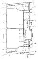
- FIG. 2 is a diagram schematically showing a state in which the tailgate of a vehicle employing the vehicle rear portion structure of the embodiment of the present invention is opened to open the luggage compartment at the rear portion of the vehicle;
- the figure which looked at the luggage compartment of the vehicle rear part shown in FIG. 1 from upper direction Partial cross-sectional view showing a state in which the cargo lid shown in FIG. 2 is removed Sectional view along IV-IV line in FIG. Enlarged view near the battery in FIG.
- Cross-sectional view along line VII-VII in FIG. 3 is an exploded perspective view of the cargo box shown in FIG.
- FIG. 1 schematically shows a state in which a tailgate (not shown) for opening and closing a luggage compartment 1 at the rear of a vehicle is opened to open the luggage compartment 1 .
- the luggage compartment 1 is an interior space behind the rear seat 2 in the longitudinal direction of the vehicle.
- the left quarter trim 3 constitutes the left side of the luggage compartment 1
- the right quarter trim 4 constitutes the right side of the luggage compartment 1 .
- the quarter trims 3 and 4 are interior members provided along the inner surface of the body 5 at the rear portion of the vehicle.
- a cargo box 6 and a cargo lid 7 covering the upper surface of the cargo box 6 are provided in the lower part of the luggage compartment 1 (see FIG. 1).
- the cargo box 6 is arranged between the rear seat 2 and the rear end panel 8 facing each other in the longitudinal direction of the vehicle.
- the upper surface of the cargo box 6 is formed with a storage recess 9 capable of storing luggage such as tools and cleaning supplies.
- the cargo lid 7 (see FIG. 2) is supported so as to be able to swing up and down with the front end of the cargo lid 7 in the longitudinal direction of the vehicle as a fulcrum.
- the cargo lid 7 on the cargo box 6 By overlapping the cargo lid 7 on the cargo box 6, the accommodation recess 9 on the upper surface of the cargo box 6 can be closed. Further, by lifting the cargo lid 7 upward, the accommodation recess 9 on the upper surface of the cargo box 6 can be opened.
- the rear portion of the vehicle is provided with a pair of left and right side members 10, 11 extending in the longitudinal direction of the vehicle, and a rear floor panel 12 supported from below by the pair of side members 10, 11. ing.
- the pair of side members 10 and 11 are arranged symmetrically with respect to the center in the vehicle width direction (horizontal direction of the vehicle).
- a lower surface of the rear floor panel 12 is fixed to upper surfaces of the side members 10 and 11 .
- the side member 10 has a C-shaped cross section having a pair of side walls 13 and 14 facing each other in the vehicle width direction and a bottom wall 15 connecting the lower ends of the pair of side walls 13 and 14 to each other. It is steel.
- a battery 16 is provided between the rear floor panel 12 and the cargo box 6 as shown in FIG.
- the battery 16 is a wet battery containing electrolyte in a fluid state.
- the battery 16 is arranged on the upper surface of the rear floor panel 12 at a position biased to one side (left side in the figure) in the vehicle width direction. In the drawing, the battery 16 is arranged so as to exist only on one side (left side in the drawing) of the upper surface of the rear floor panel 12 with respect to the central position of the rear floor panel 12 in the vehicle width direction.
- the cargo box 6 is composed of a top plate 20 disposed facing above the rear floor panel 12 so as to cover the battery 16 from above, and a top plate 20 extending downward from one end (left side in the figure) of the top plate 20 in the vehicle width direction.
- a first end plate 21 extending, a second end plate 22 extending downward from the end of the top plate 20 on the other side (right side in the figure) in the vehicle width direction, and the first end plate 21 and the battery from the top plate 20 and a box wall portion 24 extending downward from the top plate 20 through between the second end plate 22 and the battery 16 .
- the box wall portion 24 is formed in a hollow box shape with an open upper surface side of the top plate 20 so as to form the accommodation recess 9 (see FIGS. 2 and 3) inside the box wall portion 24 .
- a cargo lid 7 is superimposed on the upper surface of the top plate 20 so as to close the upper end opening of the box wall portion 24 .
- the first end plate 21 is formed integrally with the top plate 20
- the second end plate 22 is also formed integrally with the top plate 20
- the first end plate 21 is arranged to face the left quarter trim 3 in the vehicle width direction
- the second end plate 22 is also arranged to face the right quarter trim 4 in the vehicle width direction.
- the lower end of the first end plate 21 is supported by a horizontal portion 25 integrally formed with the lower end of the left quarter trim 3
- the lower end of the second end plate 22 is also integrally formed with the lower end of the right quarter trim 4 . It is supported by the formed horizontal portion 26 .
- the lower end of the first end plate 21 and the lower end of the second end plate 22 may be directly supported by the rear floor panel 12 .
- the vertical wall portion 23 is also formed in the shape of a hollow box whose upper surface side of the top plate 20 is open, so that tools, cleaning supplies, and other articles can be accommodated therein. .
- the box wall portion 24 integrally protrudes downward from the top plate 20
- the vertical wall portion 23 also integrally protrudes downward from the top plate 20 .
- the cargo box 6 including the top plate 20, the first end plate 21, the second end plate 22, the box wall portion 24, and the vertical wall portion 23 can be made of synthetic resin or synthetic rubber. If the cargo box 6 is made of synthetic rubber (e.g., ethylene propylene diene rubber), it is possible to reliably prevent the cargo box 6 from cracking when a following vehicle collides with the own vehicle.
- the battery 16 has a battery case 27 , a lid 28 provided on the upper end of the battery case 27 , and a pair of terminals 29 provided on the lid 28 .
- the battery container 27 contains a liquid electrolyte and electrodes (not shown) immersed in the electrolyte. Dilute sulfuric acid can be used as the electrolytic solution.
- a battery harness 30 is connected to each terminal 29 provided on the lid 28 .
- the battery 16 outputs a DC voltage of 12 V and supplies electric power to electrical equipment such as vehicle lamps and an air conditioner.
- a battery cover 31 that protects the battery 16 is attached to the battery 16 .
- a portion of the top plate 20 of the cargo box 6 located directly above the battery 16 serves as a battery service hole cover 33 .
- the battery service hole 32 penetrating vertically through the top plate 20 can be opened and closed.
- a battery tray 34 is provided between the battery 16 and the rear floor panel 12 to receive and support the lower surface of the battery 16 .
- the battery tray 34 has a tray bottom portion 35 on which the batteries 16 are placed, and a tray peripheral wall portion 36 rising from the peripheral edge of the tray bottom portion 35 .
- the battery tray 34 is fitted into a battery tray fitting recess 37 formed in the upper surface of the rear floor panel 12 .
- the battery tray 34 is made of resin or metal coated with an antirust coating so that it will not corrode even if the electrolyte of the battery 16 adheres to it.
- the vertical wall portion 23 is provided so as to cover the entire length of the battery 16 in the vehicle front-rear direction when viewed from the vehicle width direction. That is, the length of the vertical wall portion 23 in the vehicle front-rear direction is set longer than the length of the battery 16 in the vehicle front-rear direction, and the front end of the vertical wall portion 23 in the vehicle front-rear direction coincides with the front end of the battery 16 in the vehicle front-rear direction.
- the vertical wall portion 23 is provided such that the rear end of the vertical wall portion 23 in the vehicle front-rear direction is positioned rearward of the rear end of the battery 16 in the vehicle front-rear direction.
- the lower end portion of the vertical wall portion 23 is formed in two halves in the vehicle front-rear direction, and a space penetrating in the vehicle width direction is formed between the two tines.
- the lower end of the first end plate 21 is provided at a position overlapping the space between the two forks of the lower end of the vertical wall portion 23 when viewed in the vehicle width direction.
- a through notch 38 is formed.
- the battery harness 30 connected to the terminal 29 of the battery 16 is separated from the space between the two forks at the lower end of the vertical wall portion 23 and the notch at the lower end of the first end plate 21 . 38 in order.
- the vertical wall portion 23 has an upper portion 23 a that protrudes toward the battery 16 with respect to a lower portion 23 b of the vertical wall portion 23 when viewed from the vehicle front-rear direction. It has a stepped shape that That is, the upper portion 23a of the vertical wall portion 23 has a surface facing the battery 16 at a position closer to the battery 16 in the vehicle width direction than the surface facing the battery 16 of the lower portion 23b of the vertical wall portion 23. .
- the lower end of the surface of the upper portion 23a of the vertical wall portion 23 facing the battery 16 and the upper end of the surface of the lower portion 23b of the vertical wall portion 23 facing the battery 16 are connected via a horizontal stepped portion 23c. there is As shown in FIG.
- the end of the upper portion 23 a of the vertical wall portion 23 on the other side in the vehicle width direction (the right side in the figure) is positioned closer to the battery 16 than the position of the outer peripheral edge of the battery tray 34 . is located on the side closest to the
- the upper portion 23a of the vertical wall portion 23 has a shape that protrudes toward the battery 16 from the front side toward the rear side in the vehicle front-rear direction (a shape that approaches the battery 16) when viewed from the vertical direction.
- the width dimension in the vehicle width direction of the upper portion 23a of the vertical wall portion 23 gradually increases from the front side toward the rear side in the vehicle longitudinal direction.
- Vertical wall portions 23 are formed so that the distance between them gradually decreases.
- the first end plate 21 and the vertical wall portion 23 of the cargo box 6 are arranged directly above the side member 10 . That is, the first end plate 21 is arranged so as to have a portion overlapping the side member 10 when viewed in the vertical direction. 10 are arranged so as to have overlapping portions.
- the vertical wall portion 23 is arranged directly above the side wall 14 of the pair of side walls 13 and 14 of the side member 10 that is closer to the battery 16 .
- the first end plate 21 is arranged directly above the side wall 13 of the pair of side walls 13 and 14 of the side member 10 farther from the battery 16 .
- FIG. A vertical wall portion 23 formed integrally with the top plate 20 of the cargo box 6 is provided between the battery 16 located on the left side in the width direction. Therefore, when the following vehicle collides with the own vehicle and the battery 16 is damaged, the electrolyte that scatters from the battery 16 to the left side in the vehicle width direction can be dissipated from the vertical wall portion 23 of the cargo box 6 before the scattering spreads. can accept. Therefore, when the following vehicle collides with the own vehicle and the battery 16 mounted on the rear part of the vehicle is damaged, it is possible to prevent the electrolyte from the battery 16 from scattering.
- a vertical wall portion 23 and a first end plate 21 are provided on the outer side of the battery 16 in one of the vehicle width directions (the left direction in the drawing). Therefore, due to the layout, the battery 16 must be placed at a biased position on one side (left side in the figure) in the vehicle width direction. Even if the battery 16 is damaged by an impact or the like, the vertical wall portion 23 and the first end plate 21 act as a barrier to prevent the electrolyte from splashing into the passenger compartment.
- the structural rigidity of the cargo box 6 can be increased by the hollow box-shaped vertical wall portion 23 formed integrally with the top plate 20 .
- the vertical wall portion 23 of the cargo box 6 is formed in the shape of a hollow box in which the upper surface side of the top plate 20 is open. It is possible to store loads such as tools and cleaning supplies not only in the storage recess 9 shown, but also in the vertical wall portion 23, so that a large number of loads can be stored.
- the lower end portion of the vertical wall portion 23 is formed to be bifurcated in the vehicle front-rear direction.
- a battery harness 30 for drawing power from the battery 16 can be wired through the space between the two branches at the lower end of the vertical wall portion 23 .
- the battery harness 30 can be protected by the vertical wall portion 23, and disconnection of the battery harness 30 can be prevented.
- the upper portion 23a of the vertical wall portion 23 faces the lower portion 23b of the vertical wall portion 23 when viewed from the vehicle front-rear direction. Since the vertical wall portion 23 having a stepped shape protruding toward the battery 16 is adopted, the upper portion 23a of the vertical wall portion 23 is arranged relatively close to the battery 16, and the electrolyte splashing from the upper portion of the battery 16 is prevented. can be effectively received by the upper portion 23a of the vertical wall portion 23 before the scattering spreads. Further, since the lower portion 23b of the vertical wall portion 23 is arranged relatively far from the battery 16, other members (for example, the battery harness 30, etc.) are placed between the lower portion 23b of the vertical wall portion 23 and the battery 16. It is possible to secure the placement space.
- other members for example, the battery harness 30, etc.
- the vertical wall portion 23 has a shape that protrudes toward the battery 16 as it goes from the front side to the rear side in the vehicle front-rear direction. At the rear portion of the battery 16 in the vehicle front-rear direction, the gap between the battery 16 and the vertical wall portion 23 is narrowed, thereby effectively suppressing splashing of the electrolyte from the battery 16 .
- the gap between the battery 16 and the vertical wall portion 23 is relatively widened, so that the vertical wall portion 23 and the battery 16, it is possible to secure an arrangement space for other members (for example, the battery harness 30, a fusible link (not shown), etc.).
- the vehicle rear portion structure of this embodiment includes the first end plate 21 and the first end plate 21 of the cargo box 6 directly above the side member 10 having high rigidity against external force acting in the longitudinal direction of the vehicle. Since the vertical wall portion 23 is positioned, it is possible to suppress deformation of the first end plate 21 and the vertical wall portion 23 of the cargo box 6 when the following vehicle collides with the host vehicle. Therefore, the electrolytic solution that scatters from the battery 16 can be reliably received by the first end plate 21 and the vertical wall portion 23 of the cargo box 6 .
- the battery 16 is arranged on the left side of the rear floor panel 12 in the vehicle width direction. It is also possible to place it in a different position. In this case, the left and right configurations of the above embodiment may be interchanged.
Landscapes
- Engineering & Computer Science (AREA)
- Mechanical Engineering (AREA)
- Chemical & Material Sciences (AREA)
- Combustion & Propulsion (AREA)
- Transportation (AREA)
- Chemical Kinetics & Catalysis (AREA)
- Electrochemistry (AREA)
- General Chemical & Material Sciences (AREA)
- Aviation & Aerospace Engineering (AREA)
- Body Structure For Vehicles (AREA)
- Vehicle Step Arrangements And Article Storage (AREA)
- Battery Mounting, Suspending (AREA)
Priority Applications (1)
| Application Number | Priority Date | Filing Date | Title |
|---|---|---|---|
| JP2023532043A JP7424547B2 (ja) | 2021-06-30 | 2022-06-30 | 車両の後部構造 |
Applications Claiming Priority (2)
| Application Number | Priority Date | Filing Date | Title |
|---|---|---|---|
| JP2021108543 | 2021-06-30 | ||
| JP2021-108543 | 2021-06-30 |
Publications (1)
| Publication Number | Publication Date |
|---|---|
| WO2023277115A1 true WO2023277115A1 (ja) | 2023-01-05 |
Family
ID=84691868
Family Applications (1)
| Application Number | Title | Priority Date | Filing Date |
|---|---|---|---|
| PCT/JP2022/026148 Ceased WO2023277115A1 (ja) | 2021-06-30 | 2022-06-30 | 車両の後部構造 |
Country Status (2)
| Country | Link |
|---|---|
| JP (1) | JP7424547B2 (https=) |
| WO (1) | WO2023277115A1 (https=) |
Cited By (1)
| Publication number | Priority date | Publication date | Assignee | Title |
|---|---|---|---|---|
| JP2024130117A (ja) * | 2023-03-14 | 2024-09-30 | 株式会社豊田自動織機 | 車両用デッキ装置 |
Citations (4)
| Publication number | Priority date | Publication date | Assignee | Title |
|---|---|---|---|---|
| JP2012179963A (ja) * | 2011-02-28 | 2012-09-20 | Toyota Auto Body Co Ltd | 車両の荷室構造 |
| US20170008574A1 (en) * | 2015-07-07 | 2017-01-12 | GM Global Technology Operations LLC | Motor vehicle and floor module for the latter |
| JP2020019444A (ja) * | 2018-08-03 | 2020-02-06 | トヨタ自動車株式会社 | 車両の荷室 |
| JP2020111306A (ja) * | 2019-01-17 | 2020-07-27 | 本田技研工業株式会社 | 車両用荷室構造 |
-
2022
- 2022-06-30 JP JP2023532043A patent/JP7424547B2/ja active Active
- 2022-06-30 WO PCT/JP2022/026148 patent/WO2023277115A1/ja not_active Ceased
Patent Citations (4)
| Publication number | Priority date | Publication date | Assignee | Title |
|---|---|---|---|---|
| JP2012179963A (ja) * | 2011-02-28 | 2012-09-20 | Toyota Auto Body Co Ltd | 車両の荷室構造 |
| US20170008574A1 (en) * | 2015-07-07 | 2017-01-12 | GM Global Technology Operations LLC | Motor vehicle and floor module for the latter |
| JP2020019444A (ja) * | 2018-08-03 | 2020-02-06 | トヨタ自動車株式会社 | 車両の荷室 |
| JP2020111306A (ja) * | 2019-01-17 | 2020-07-27 | 本田技研工業株式会社 | 車両用荷室構造 |
Cited By (2)
| Publication number | Priority date | Publication date | Assignee | Title |
|---|---|---|---|---|
| JP2024130117A (ja) * | 2023-03-14 | 2024-09-30 | 株式会社豊田自動織機 | 車両用デッキ装置 |
| JP7845236B2 (ja) | 2023-03-14 | 2026-04-14 | 株式会社豊田自動織機 | 車両用デッキ装置 |
Also Published As
| Publication number | Publication date |
|---|---|
| JP7424547B2 (ja) | 2024-01-30 |
| JPWO2023277115A1 (https=) | 2023-01-05 |
Similar Documents
| Publication | Publication Date | Title |
|---|---|---|
| JP5829706B2 (ja) | 車載用バッテリー | |
| US9975416B2 (en) | Vehicle body structure and onboard battery for vehicle | |
| CN107546346B (zh) | 车载用蓄电池 | |
| US9873456B2 (en) | Onboard battery for vehicle | |
| US10189371B2 (en) | Electrically-powered vehicle | |
| CN101395022A (zh) | 蓄电组的车载构造 | |
| CN116638955A (zh) | 后部车体构造 | |
| JP5375727B2 (ja) | 蓄電パックの車両搭載構造 | |
| KR20210071116A (ko) | 고전압배터리가 장착되는 차체 | |
| CN116638954A (zh) | 后部车体构造 | |
| CN116638953A (zh) | 车体构造 | |
| CN101312855B (zh) | 束线排布结构 | |
| CN108116498A (zh) | 车辆下部结构 | |
| WO2023277115A1 (ja) | 車両の後部構造 | |
| CN214028868U (zh) | 车身后部构造 | |
| CN114987179B (zh) | 车辆搭载用电池封装体 | |
| JP2005247064A (ja) | 蓄電機構の搭載構造 | |
| JP2017144819A (ja) | 電子機器の車載構造 | |
| CN219007933U (zh) | 后纵梁连接件和汽车车架 | |
| JP6629515B2 (ja) | 車載用バッテリー | |
| JP4580200B2 (ja) | 電動式フォークリフトの電装品カバー装置 | |
| CN115817642A (zh) | 后纵梁连接件和汽车车架 | |
| KR20230051763A (ko) | 냉각 모듈 뒤에 배치된 충돌 구조물을 구비한 자동차의 전방 단부 구조물 | |
| JP7316508B2 (ja) | 車両の下部構造 | |
| JP2013103690A (ja) | 車両の電池支持構造 |
Legal Events
| Date | Code | Title | Description |
|---|---|---|---|
| 121 | Ep: the epo has been informed by wipo that ep was designated in this application |
Ref document number: 22833261 Country of ref document: EP Kind code of ref document: A1 |
|
| WWE | Wipo information: entry into national phase |
Ref document number: 2023532043 Country of ref document: JP |
|
| WWE | Wipo information: entry into national phase |
Ref document number: 2301008555 Country of ref document: TH |
|
| NENP | Non-entry into the national phase |
Ref country code: DE |
|
| 122 | Ep: pct application non-entry in european phase |
Ref document number: 22833261 Country of ref document: EP Kind code of ref document: A1 |