WO2023276852A1 - 融着接続機及びv溝清掃用治具 - Google Patents
融着接続機及びv溝清掃用治具 Download PDFInfo
- Publication number
- WO2023276852A1 WO2023276852A1 PCT/JP2022/025135 JP2022025135W WO2023276852A1 WO 2023276852 A1 WO2023276852 A1 WO 2023276852A1 JP 2022025135 W JP2022025135 W JP 2022025135W WO 2023276852 A1 WO2023276852 A1 WO 2023276852A1
- Authority
- WO
- WIPO (PCT)
- Prior art keywords
- groove
- optical fiber
- group
- fusion splicer
- foreign matter
- Prior art date
- Legal status (The legal status is an assumption and is not a legal conclusion. Google has not performed a legal analysis and makes no representation as to the accuracy of the status listed.)
- Ceased
Links
Images










Classifications
-
- G—PHYSICS
- G02—OPTICS
- G02B—OPTICAL ELEMENTS, SYSTEMS OR APPARATUS
- G02B6/00—Light guides; Structural details of arrangements comprising light guides and other optical elements, e.g. couplings
- G02B6/24—Coupling light guides
- G02B6/255—Splicing of light guides, e.g. by fusion or bonding
- G02B6/2555—Alignment or adjustment devices for aligning prior to splicing
- G02B6/2556—Alignment or adjustment devices for aligning prior to splicing including a fibre supporting member inclined to the bottom surface of the alignment means
-
- B—PERFORMING OPERATIONS; TRANSPORTING
- B08—CLEANING
- B08B—CLEANING IN GENERAL; PREVENTION OF FOULING IN GENERAL
- B08B1/00—Cleaning by methods involving the use of tools
- B08B1/10—Cleaning by methods involving the use of tools characterised by the type of cleaning tool
- B08B1/16—Rigid blades, e.g. scrapers; Flexible blades, e.g. wipers
- B08B1/165—Scrapers
-
- B—PERFORMING OPERATIONS; TRANSPORTING
- B08—CLEANING
- B08B—CLEANING IN GENERAL; PREVENTION OF FOULING IN GENERAL
- B08B1/00—Cleaning by methods involving the use of tools
- B08B1/30—Cleaning by methods involving the use of tools by movement of cleaning members over a surface
-
- G—PHYSICS
- G02—OPTICS
- G02B—OPTICAL ELEMENTS, SYSTEMS OR APPARATUS
- G02B6/00—Light guides; Structural details of arrangements comprising light guides and other optical elements, e.g. couplings
- G02B6/24—Coupling light guides
- G02B6/255—Splicing of light guides, e.g. by fusion or bonding
- G02B6/2553—Splicing machines, e.g. optical fibre fusion splicer
-
- G—PHYSICS
- G02—OPTICS
- G02B—OPTICAL ELEMENTS, SYSTEMS OR APPARATUS
- G02B6/00—Light guides; Structural details of arrangements comprising light guides and other optical elements, e.g. couplings
- G02B6/24—Coupling light guides
- G02B6/255—Splicing of light guides, e.g. by fusion or bonding
- G02B6/2555—Alignment or adjustment devices for aligning prior to splicing
-
- G—PHYSICS
- G02—OPTICS
- G02B—OPTICAL ELEMENTS, SYSTEMS OR APPARATUS
- G02B6/00—Light guides; Structural details of arrangements comprising light guides and other optical elements, e.g. couplings
- G02B6/24—Coupling light guides
- G02B6/255—Splicing of light guides, e.g. by fusion or bonding
- G02B6/2555—Alignment or adjustment devices for aligning prior to splicing
- G02B6/2557—Alignment or adjustment devices for aligning prior to splicing using deformable flexure members, flexible hinges or pivotal arms
-
- G—PHYSICS
- G02—OPTICS
- G02B—OPTICAL ELEMENTS, SYSTEMS OR APPARATUS
- G02B6/00—Light guides; Structural details of arrangements comprising light guides and other optical elements, e.g. couplings
- G02B6/24—Coupling light guides
- G02B6/36—Mechanical coupling means
- G02B6/3628—Mechanical coupling means for mounting fibres to supporting carriers
- G02B6/3648—Supporting carriers of a microbench type, i.e. with micromachined additional mechanical structures
- G02B6/3652—Supporting carriers of a microbench type, i.e. with micromachined additional mechanical structures the additional structures being prepositioning mounting areas, allowing only movement in one dimension, e.g. grooves, trenches or vias in the microbench surface, i.e. self aligning supporting carriers
Definitions
- the present disclosure relates to a fusion splicer and a V-groove cleaning jig.
- Patent Document 1 Conventionally, there is known a method of positioning an optical fiber to be spliced in a V-groove and performing fusion splicing (see Patent Document 1).
- a fusion splicer is a fusion splicer for fusion splicing an optical fiber, comprising a base member having a V-groove in which the optical fiber is installed, and an inclined surface of the V-groove is provided with a stepped portion, and the stepped portion is provided at a position in contact with the optical fiber.
- FIG. 1 is a perspective view of a portion of a fusion splicer.
- FIG. 2A is a top view of a portion of a fusion splicer.
- FIG. 2B is a top view of a portion of the fusion splicer.
- FIG. 3 is a cross-sectional view of part of a fusion splicer.
- FIG. 4 is a block diagram showing a control system for controlling the fusion splicer.
- FIG. 5 is a perspective view of part of a fusion splicer.
- FIG. 6A is a top view of an example of a first left V-groove.
- 6B is a top view of the first left V-groove and first left optical fiber of FIG. 6A.
- FIG. 6C is a cross-sectional view of the first left V-groove and the first left optical fiber of FIG. 6A.
- FIG. 6D is a top view of another example of the first left V-groove of FIG. 6A.
- FIG. 7A is a perspective view of a jig;
- FIG. 7B is a right side view of the jig of FIG. 7A.
- 7C is a right side view of another example of the fixture of FIG. 7A.
- 7D is a right side view of yet another example of the fixture of FIG. 7A.
- FIG. 8A is a top view of another example of the first left V-groove.
- 8B is a top view of the first left V-groove and first left optical fiber of FIG. 8A.
- FIG. 8C is a cross-sectional view of the first left V-groove and the first left optical fiber of FIG. 8A.
- FIG. 8D is a top view of another example of the first left V-groove of FIG. 8A.
- FIG. 8E is a top view of yet another example of the first left V-groove of FIG. 8A.
- FIG. 9A is a top view of still another example of the first left V-groove.
- 9B is a top view of the first left V-groove and first left optical fiber of FIG. 9A.
- 9C is a cross-sectional view of the first left V-groove and first left optical fiber of FIG. 9A.
- FIG. 10A is a top view of still another example of the first left V-groove.
- FIG. 10A is a top view of still another example of the first left V-groove.
- FIG. 10B is a top view of the first left V-groove and first left optical fiber of FIG. 10A.
- FIG. 10C is a cross-sectional view of the first left V-groove and first left optical fiber of FIG. 10A.
- FIG. 11A is a top view of still another example of the first left V-groove.
- FIG. 11B is a top view of the first left V-groove and first left optical fiber of FIG. 11A.
- FIG. 11C is a cross-sectional view of the first left V-groove and first left optical fiber of FIG. 11A.
- FIG. 12A is a top view of still another example of the first left V-groove. 12B is a cross-sectional view of the first left V-groove of FIG. 12A.
- FIG. 12C is a top view of another example of the first left V-groove of FIG. 12A.
- Patent Literature 1 discloses a method for removing foreign matter adhering between an optical fiber and a V-groove. However, in this method, it is necessary to perform an operation for positively removing the foreign matter in addition to the normal fusion splicing operation. Therefore, it is desirable to reduce the additional work for removing the foreign matter as much as possible.
- a fusion splicer is a fusion splicer for fusion splicing optical fibers, comprising a base member having a V-groove in which the optical fiber is installed, the V-groove A stepped portion may be provided on the inclined surface of the stepped portion, and the stepped portion may be provided at a position in contact with the optical fiber. This configuration reduces the surface area of the portion of the inclined surface (groove surface) of the V-groove that is in contact with the optical fiber, thereby reducing the probability of foreign matter adhering to that portion.
- this configuration has the effect of reducing the probability that a foreign object will be caught between the optical fiber and the V-groove when the optical fiber is installed in the V-groove.
- This configuration then has the advantage that the optical fiber is accurately positioned within the V-groove.
- the portion of the optical fiber that is installed in the V-groove is the portion where the coating material is removed and the glass fiber is exposed, and is also called a bare fiber portion.
- the portion coated with the coating material is also called an optical fiber bare wire or an optical fiber core wire.
- a fusion splicer is a fusion splicer for fusion splicing optical fibers, comprising a base member having a V-groove in which the optical fiber is installed, the V-groove A stepped portion may be provided on the inclined surface of the stepped portion, and the stepped portion may be a concave portion provided on the bottom portion of the V-groove.
- This configuration has an effect that since there is a region where foreign matter is accumulated at the bottom of the V-groove, foreign matter can be prevented from being caught between the optical fiber and the V-groove when the optical fiber is installed in the V-groove. bring.
- This configuration then has the advantage that the optical fiber is accurately positioned within the V-groove.
- the recess may be a through hole penetrating through the base member.
- This configuration allows foreign matter entering the V-groove to be discharged out of the V-groove through the through-hole. Therefore, this configuration has the effect of suppressing foreign matter from being caught between the optical fiber and the V-groove when the optical fiber is installed in the V-groove. This configuration then has the advantage that the optical fiber is accurately positioned within the V-groove.
- the optical fibers may be a plurality of optical fibers
- the V-grooves may be a plurality of V-grooves in which the plurality of optical fibers are installed.
- the stepped portion is provided in at least one of the plurality of V-grooves.
- a V-groove cleaning jig used for cleaning the V-groove in the fusion splicer has a sliding surface that contacts a support surface that constitutes a part of the inclined surface.
- the cleaning of the V-groove is, for example, the removal of foreign matter adhering to the groove surface of the V-groove.
- the V-groove cleaning jig may be configured to be slidable in the extending direction of the V-groove while the support surface and the sliding surface are in contact with each other.
- the support surface may be a surface that contacts the optical fiber and supports the optical fiber.
- This V-groove cleaning jig can peel off foreign matter attached to the support surface before the optical fiber is installed in the V-groove. Therefore, when the optical fiber is installed in the V-groove, it is possible to prevent foreign matter from being caught between the optical fiber and the V-groove.
- This V-groove cleaning jig has the effect of allowing the optical fiber to be accurately positioned within the V-groove.
- FIG. 1 is a perspective view showing part of the fusion splicer 1.
- X1 represents one direction of the X-axis forming the three-dimensional orthogonal coordinate system
- X2 represents the other direction of the X-axis
- Y1 represents one direction of the Y-axis forming the three-dimensional orthogonal coordinate system
- Y2 represents the other direction of the Y-axis
- Z1 represents one direction of the Z-axis forming the three-dimensional orthogonal coordinate system
- Z2 represents the other direction of the Z-axis.
- the X1 side of the fusion splicer 1 corresponds to the front side (front side) of the fusion splicer 1
- the X2 side of the fusion splicer 1 corresponds to the rear side (back side) of the fusion splicer 1. side).
- the Y1 side of the fusion splicer 1 corresponds to the left side of the fusion splicer 1
- the Y2 side of the fusion splicer 1 corresponds to the right side of the fusion splicer 1 .
- the Z1 side of the fusion splicer 1 corresponds to the upper side of the fusion splicer 1
- the Z2 side of the fusion splicer 1 corresponds to the lower side of the fusion splicer 1 .
- the fusion splicer 1 is a device configured to fusion splice a plurality of pairs of optical fibers arranged with their end faces facing each other by arc discharge.
- the fusion splicer 1 is configured to be capable of fusion splicing four optical fiber pairs.
- the fusion splicer 1 includes a pair of electrode rods 5 (rear electrode rod 5B and front electrode rod 5F), a pair of base members 11 (left base member 11L and right base member 11R), and a pair of It includes a clamp 21 (a left clamp 21L and a right clamp 21R) and a pair of fiber holders 31 (a left fiber holder 31L and a right fiber holder 31R).
- the pair of electrode rods 5 includes a rear electrode rod 5B and a front electrode rod 5F that are spaced apart from each other in the X-axis direction.
- the pair of electrode rods 5 are arranged such that the tip 5Ba of the rear electrode rod 5B and the tip 5Fa of the front electrode rod 5F face each other.
- the rear electrode rod 5B includes a conical portion whose diameter decreases toward the tip 5Ba. The same applies to the front electrode rod 5F.
- a plurality of pairs of optical fibers arranged on the pair of base members 11 are glass fibers and arranged between the rear electrode rod 5B and the front electrode rod 5F for generating arc discharge. Also, among the plurality of pairs of optical fibers, the portions placed on the pair of base members 11 are bare fiber portions where the coating material is removed and the glass fibers are exposed.
- the plurality of pairs of bare fiber portions include the bare fiber portion of the left optical fiber group 3L that constitutes the left optical fiber ribbon 4L and the bare fiber portion of the right optical fiber group 3R that constitutes the right optical fiber ribbon 4R. including.
- the left optical fiber group 3L and the right optical fiber group 3R may be referred to as the optical fiber group 3 for convenience of explanation.
- a tape core wire is made by arranging multiple optical fibers (optical fiber strands) in parallel and coating them collectively with, for example, an ultraviolet curable resin (coating material).
- Each of the left optical fiber ribbon 4L and the right optical fiber ribbon 4R in the illustrated example is a four-fiber tape core in which four optical fibers (optical fiber bare wires) are arranged in parallel and collectively coated with an ultraviolet curable resin (coating material). is a line.
- the pair of base members 11 are members for supporting a plurality of pairs of optical fibers, and include a left base member 11L and a right base member 11R arranged so as to sandwich the pair of electrode rods 5 therebetween. That is, the pair of electrode rods 5 are arranged between the left base member 11L and the right base member 11R which are arranged apart from each other in the Y-axis direction.
- the illustrated right base member 11R has a right V-groove group 17R, also referred to as a right optical fiber placement portion or right groove portion, and the left base member 11L is also referred to as a left optical fiber placement portion or left groove portion. It has a left V groove group 17L. Note that, hereinafter, the left V-groove group 17L and the right V-groove group 17R may be referred to as the V-groove group 17 for convenience of explanation.
- the left V-groove group 17L has a plurality of V-grooves for arranging a plurality of optical fibers (left optical fiber group 3L), and the right V-groove group 17R has a plurality of optical fibers (right optical fiber group 3R). ) for arranging a plurality of V-grooves.
- the left V-groove group 17L has four V-grooves for arranging four optical fibers.
- the four V-grooves are arranged at equal intervals in the X-axis direction and formed to extend linearly along the Y-axis direction.
- right V-groove group 17R has four V-grooves for arranging four optical fibers.
- the four V-grooves are arranged at equal intervals in the X-axis direction and formed to extend linearly along the Y-axis direction.
- the plurality of V-grooves in the right V-groove group 17R and the plurality of V-grooves in the left V-groove group 17L are configured so that positioning of a plurality of optical fiber pairs can be performed simultaneously.
- the four V-grooves in the right V-groove group 17R and the four V-grooves in the left V-groove group 17L are arranged to face each other in the extending direction (Y-axis direction), forming four optical fiber pairs. are configured to be positioned at the same time.
- the four optical fibers positioned by the four V-grooves in the right V-groove group 17R and the four optical fibers positioned by the four V-grooves in the left V-groove group 17L are connected to the right base member 11R. (Right V-groove group 17R) and Left base member 11L (Left V-groove group 17L) abut against each other.
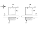
- FIGS. 2A and 2B are top views showing part of the fusion splicer 1.
- FIGS. 2A and 2B are top views of the electrode rod 5 and the base member 11.
- FIG. 2A shows the state before the optical fiber group 3 is installed in the V-groove group 17
- FIG. 2B shows the state after the optical fiber group 3 is installed in the V-groove group 17. show.
- a rough dot pattern is given to the groove surface of the V groove group 17 for clarity.
- the bottom of each V-groove is indicated by a dashed line.
- the left V-groove group 17L includes a first left V-groove 17AL, a second left V-groove 17BL, a third left V-groove 17CL, and a fourth left V-groove 17DL, and a right V-groove group 17R.
- a first right V-groove 17AR includes a first right V-groove 17AR, a second right V-groove 17BR, a third right V-groove 17CR, and a fourth right V-groove 17DR.
- the first left V-groove 17AL and the first right V-groove 17AR form a first V-groove pair 17A
- the second left V-groove 17BL and the second right V-groove 17BR form a second V-groove pair 17B
- the third left V-groove 17CL and the third right V-groove 17CR constitute a third V-groove pair 17C
- the fourth left V-groove 17DL and the fourth right V-groove 17DR constitute a fourth V-groove pair 17D.
- the left optical fiber group 3L includes a first left optical fiber 3AL, a second left optical fiber 3BL, a third left optical fiber 3CL, and a fourth left optical fiber 3DL as bare fiber portions.
- the right optical fiber group 3R includes a first right optical fiber 3AR, a second right optical fiber 3BR, a third right optical fiber 3CR, and a fourth right optical fiber 3DR as bare fiber portions.
- the first left optical fiber 3AL and the first right optical fiber 3AR constitute a first optical fiber pair 3A
- the second left optical fiber 3BL and the second right optical fiber 3BR constitute a second optical fiber pair 3B.
- the third left optical fiber 3CL and the third right optical fiber 3CR constitute a third optical fiber pair 3C
- the fourth left optical fiber 3DL and the fourth right optical fiber 3DR constitute a fourth optical fiber pair 3D. do.
- FIG. 3 is a cross-sectional view showing part of the fusion splicer 1. As shown in FIG. Specifically, FIG. 3 is a view of the cross section including the section line III-III in FIG. 2B viewed from the X1 side as indicated by the arrow. In addition, the cross section in FIG. 2B includes the cross section of the base member 11 .
- the left clamp 21L is configured to be able to relatively press the left optical fiber group 3L installed in the left V-groove group 17L against the left V-groove group 17L.
- the right clamp 21R is configured to relatively press the right optical fiber group 3R installed in the right V-groove group 17R against the right V-groove group 17R.
- the left clamp 21L includes a left arm portion 21La and a left pressing portion 21Lb
- the right clamp 21R includes a right arm portion 21Ra and a right pressing portion 21Rb.
- the left arm portion 21La is arranged above the left V-groove group 17L
- the right arm portion 21Ra is arranged above the right V-groove group 17R.
- the left arm portion 21La and the right arm portion 21Ra are configured to be movable in the Z-axis direction.
- the left arm portion 21La and the right arm portion 21Ra may have, for example, a rectangular columnar outer shape as shown in FIG.
- the left pressing portion 21Lb may be attached to the lower end of the left arm portion 21La
- the right pressing portion 21Rb may be attached to the lower end of the right arm portion 21Ra.
- the left pressing portion 21Lb is movable in the Z-axis direction at the lower end of the left arm portion 21La
- the right pressing portion 21Rb is movable in the Z-axis direction at the lower end of the right arm portion 21Ra. In the state shown in FIG.
- the left pressing portion 21Lb is separated from the left optical fiber group 3L installed in the left V-groove group 17L. , and the left optical fiber group 3L, and can press the left optical fiber group 3L toward the left V-groove group 17L. The same applies to the right pressing portion 21Rb.
- the left clamp 21L may be configured so that the clamping pressure can be changed.
- the clamp pressure is the pressure that the left optical fiber group 3L placed in the left V-groove group 17L receives from the left pressing portion 21Lb of the left clamp 21L.
- An elastic body such as a spring may be arranged between the left arm portion 21La and the left pressing portion 21Lb to urge the left pressing portion 21Lb downward.
- the left clamp 21L can control the clamp pressure by controlling the position of the left arm portion 21La in the Z-axis direction. The same applies to the right clamp 21R.
- the left fiber holder 31L is configured to hold the left optical fiber group 3L
- the right fiber holder 31R is configured to hold the right optical fiber group 3R.
- the left fiber holder 31L is configured to hold the left ribbon core 4L including the left optical fiber group 3L
- the right fiber holder 31R is configured to hold the right ribbon core 4R including the right optical fiber group 3R. configured to hold.
- the left fiber holder 31L includes a left fiber holder main body 31La having a recess (not shown) for accommodating the left ribbon fiber 4L, and a left lid attached to the left fiber holder main body 31La. 31 Lb.
- the right fiber holder 31R includes a right fiber holder main body 31Ra having a recess (not shown) for accommodating the right fiber ribbon 4R, and a right lid 31Rb attached to the right fiber holder main body 31Ra. have.
- the left fiber ribbon 4L is held by the left fiber holder 31L by closing the left lid 31Lb while the left fiber holder main body 31La accommodates the left fiber ribbon 4L.
- the left fiber holder 31L is movable in a direction along the axial direction of the left optical fiber group 3L that it holds. That is, the left fiber holder 31L can move along the extending direction (Y-axis direction) of the left V-groove group 17L.
- the held left optical fiber group 3L can move along the left V-groove group 17L.
- the right fiber ribbon 4R is held in the right fiber holder 31R by closing the right lid 31Rb while the right fiber holder body 31Ra accommodates the right fiber ribbon 4R.
- the right fiber holder 31R is movable in the axial direction of the held right optical fiber group 3R. That is, the right fiber holder 31R is movable along the extending direction (Y-axis direction) of the right V-groove group 17R.
- the held right optical fiber group 3R can move along the right V-groove group 17R.
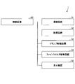
- FIG. 4 is a block diagram showing a control system for controlling the fusion splicer 1. As shown in FIG. 4
- the fusion splicer 1 includes an imaging device 51, a fusion device 52, a clamp driving device 53, a fiber holder driving device 54, a display device 55, and a control device 60.
- the imaging device 51 , the fusing device 52 , the clamp driving device 53 , the fiber holder driving device 54 and the display device 55 are controlled by the control device 60 .
- the control device 60 is, for example, a computer equipped with a CPU (Central Processing Unit), RAM (Random Access Memory), ROM (Read Only Memory), a communication module, and an external storage device.
- CPU Central Processing Unit
- RAM Random Access Memory
- ROM Read Only Memory
- communication module an external storage device.
- the imaging device 51 includes, for example, a pair of cameras (X camera and Y camera). Both the X camera and the Y camera can simultaneously image the end of the left optical fiber group 3L installed in the left V-groove group 17L and the end of the right optical fiber group 3R installed in the right V-groove group 17R. are arranged as Also, the imaging direction of the X camera and the imaging direction of the Y camera are orthogonal to each other.
- the control device 60 can identify the position of the optical fiber group 3 based on the images of the optical fiber group 3 captured from two different directions by the pair of cameras.
- the fusion splicer 52 is a device that fusion splices the end of the left optical fiber group 3L and the end of the right optical fiber group 3R.
- a pair of electrode rods 5 are included in a fusion device 52 .
- the clamp drive device 53 is a device for pressing the optical fiber group 3 against the V groove group 17 relatively.
- the clamp driving device 53 includes actuators that move the left arm portion 21La that forms the left clamp 21L and the right arm portion 21Ra that forms the right clamp 21R in the Z-axis direction.
- the fiber holder driving device 54 is a device for moving the optical fiber group 3 in the axial direction (Y-axis direction).
- the fiber holder driving device 54 includes an actuator that moves the left fiber holder 31L in a direction along the axial direction (Y-axis direction) of the left optical fiber group 3L, and an actuator that moves the left fiber holder 31L in the axial direction (Y-axis direction) of the right optical fiber group 3R. Y-axis direction) to move the right fiber holder 31R.
- the display device 55 is a device for displaying various information.
- the display device 55 is configured to display the image captured by the imaging device 51 .
- the display device 55 is a liquid crystal display.
- the control device 60 is a device for controlling each of the imaging device 51, the fusion splicing device 52, the clamp driving device 53, the fiber holder driving device 54, and the display device 55.
- the control device 60 acquires an image captured by the imaging device 51 by controlling the imaging device 51 .
- the control device 60 can cause the display device 55 to display the acquired image, for example.
- the control device 60 can determine the state of one or more pairs of optical fibers by performing image processing on the acquired image. Further, the control device 60 can generate an arc discharge between the rear electrode rod 5B and the front electrode rod 5F by controlling the fusing device 52 .
- control device 60 can move the left arm portion 21La of the left clamp 21L and the right arm portion 21Ra of the right clamp 21R in the Z-axis direction by controlling the clamp driving device 53 .
- the left clamp 21L can change the pressing state of the left optical fiber group 3L arranged in the left V-groove group 17L
- the right clamp 21R can change the pressing state of the right optical fiber group 3L arranged in the right V-groove group 17R.
- the pressing state of the fiber group 3R can be changed.
- the control device 60 can control the positions of the left fiber holder 31L and the right fiber holder 31R in the Y-axis direction by controlling the fiber holder drive device 54 .
- control device 60 can move the left optical fiber group 3L held by the left fiber holder 31L in the Y-axis direction by moving the left fiber holder 31L in the Y-axis direction.
- the right optical fiber group 3R held by the right fiber holder 31R can be moved in the Y-axis direction.
- the V-groove group 17 is used for positioning the optical fiber group 3 to be fusion-spliced. There is a risk that you will not be able to
- FIG. 5 shows an example of the state of the optical fiber when foreign matter is present in the V-groove. Specifically, FIG. 5 shows, for clarity, the first left optical fiber 3AL installed in the first left V-groove 17AL when an extremely large foreign object G adheres to the first left V-groove 17AL. and the state of the first right optical fiber 3AR installed in the first right V-groove 17AR to which foreign matter is not attached.
- a step portion ST is formed in each of the V-groove groups 17 in the fusion splicer 1 according to this embodiment.
- the stepped portion ST is a portion (structure) formed in the V-groove.
- the stepped portion ST is formed so as to prevent foreign matter from adhering to the portion of the groove surface of the V-groove that is expected to come into contact with the optical fiber.
- the step ST is a convex structure formed on the groove surface of the V-groove that contacts the optical fiber when the optical fiber is placed in the V-groove. is configured to
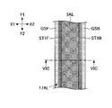
- FIGS. 6A to 6D are diagrams showing configuration examples of the first left V-groove 17AL.
- FIG. 6A is a top view of the first left V-groove 17AL before the first left optical fiber 3AL is installed.
- FIG. 6B is a top view of the first left V-groove 17AL after the first left optical fiber 3AL is installed.
- FIG. 6C is a view of the section including the section line VIC-VIC in FIG. 6B as viewed from the Y2 side as indicated by the arrow.
- FIG. 6D is a top view of the first left V-groove 17AL including another configuration example of the step ST.
- FIGS. 1 is a top view of the first left V-groove 17AL before the first left optical fiber 3AL is installed.
- FIG. 6B is a top view of the first left V-groove 17AL after the first left optical fiber 3AL is installed.
- FIG. 6C is a view of the section including the section line VIC-VIC
- the groove surface GS is provided with a rough dot pattern
- the step ST formed on the groove surface GS is provided with a fine dot pattern.
- the first left optical fiber 3AL is given a cross pattern for clarity.
- FIGS. 6A to 6C show a pressing guide ST1, which is an example of the stepped portion ST.
- the pressing guide ST1 is a portion that sandwiches and presses the optical fiber from both sides within the V-groove and guides the optical fiber along the extending direction of the V-groove.
- the pressing guide ST1 includes a front pressing guide ST1F formed on the front groove surface GSF of the first left V-groove 17AL and a rear pressing guide ST1F formed on the rear groove surface GSB of the first left V-groove 17AL. ST1B.
- the front pressing guide ST1F has a rectangular cross section as shown in FIG. 6C, and is formed to extend continuously over the entire length of the first left V-groove 17AL as shown in FIG. 6A. The same applies to the rear pressing guide ST1B.
- the support surface RF including the contact portion CT (the portion represented by the dashed line in FIGS. 6A and 6C), which is the portion where the first left optical fiber 3AL and the pressing guide ST1 are in contact, protrudes from the groove surface GS.
- the pressing guide ST1 may be arranged intermittently along the axial direction of the first left V-groove 17AL, as shown in FIG. 6D. Since this configuration can further reduce the surface area of the support surface RF, it is possible to further suppress foreign matter from adhering to the support surface RF.
- the pressing guide ST1 is formed to have a rectangular cross-section as shown in FIG. 6C, it may have another cross-sectional shape such as a trapezoid.
- FIGS. 7A to 7D are diagrams showing configuration examples of the jig 70.
- FIG. 7A is a perspective view of jig 70 and FIG. 7B is a right side view of jig 70 .
- 7C is a right side view of another configuration example of the jig 70, and
- FIG. 7D is a right side view of still another configuration example of the jig 70.
- FIG. 7A is a perspective view of jig 70 and FIG. 7B is a right side view of jig 70 .
- 7C is a right side view of another configuration example of the jig 70
- FIG. 7D is a right side view of still another configuration example of the jig 70.
- the jig 70 is a jig used when cleaning the V-groove having a groove surface in which the pressing guide ST1 shown in FIGS. 6A to 6D is formed.
- the operator can bring the sliding surface 71 of the jig 70 into contact with the groove surface GS of the V-groove while gripping the grip portion HD.
- the jig 70 is used for cleaning the first left V-groove 17AL. 17DR are similarly used in cleaning.
- the jig 70 has a sliding surface 71 configured to come into contact with the groove surface GS of the first left V-groove 17AL.
- the sliding surface 71 includes a front sliding surface 71F formed to contact the front groove surface GSF (see FIG. 6C) and a rear groove surface GSB (see FIG. 6C). and a rear sliding surface 71B formed in the .
- the front sliding surface 71F is composed of a central sliding surface 71MF formed to contact the support surface RF of the front pressing guide ST1F and a front groove surface GSF above the front pressing guide ST1F. It includes an upper sliding surface 71UF formed to contact a portion and a lower sliding surface 71DF formed to contact a portion of the front groove surface GSF below the front hold down guide ST1F.
- the rear sliding surface 71B consists of a central sliding surface 71MB formed to contact the support surface RF of the rear pressing guide ST1B and a rear groove surface GSB located above the rear pressing guide ST1B. It includes an upper sliding surface 71UB formed to contact a portion and a lower sliding surface 71DB formed to contact a portion of the rear groove surface GSB below the rear pressing guide ST1B. .
- the sliding surface 71 also includes a tip portion 71E formed to contact the bottom of the first left V-groove 17AL at a portion where the front sliding surface 71F and the rear sliding surface 71B contact each other.
- the jig 70 is moved from the Y1 side or the Y2 side of the first left V-groove 17AL into the first left V-groove 17AL so that the sliding surface 71 and the groove surface GS of the first left V-groove 17AL are in surface contact with each other. be fitted in. Then, the jig 70 slides in the extending direction (Y-axis direction) of the first left V-groove 17AL while the sliding surface 71 and the groove surface GS of the first left V-groove 17AL are in surface contact. Let me.
- the jig 70 can scrape off foreign matter adhering to the groove surface GS of the first left V-groove 17AL and push the scraped-off foreign matter out of the first left V-groove 17AL.
- the contour of the sliding surface 71 of the jig 70 (see FIG. 7B) and the contour of the groove surface GS of the first left V-groove 17AL (see FIG. 6C) are on the right side. They match in appearance. Therefore, the jig 70 can scrape off or push out foreign matter adhering to the bottom of the first left V-groove 17AL as well as the foreign matter adhering to the upper and lower end faces of the front pressing guide ST1F.
- the jig 70 may be configured to have contours as shown in FIG. 7C or FIG. 7D. 7C and 7D, for comparison, the outline of the jig 70 in FIG. 7B is indicated by a dashed line.
- the jig 70 shown in FIG. 7C differs from the jig 70 shown in FIG. 7B in that the tip portion 71E is omitted. Specifically, the jig 70 shown in FIG. 7C has a bottom surface that connects the lower end of the lower sliding surface 71DF of the front sliding surface 71F and the lower end of the lower sliding surface 71DB of the rear sliding surface 71B. It differs from the jig 70 shown in FIG. 7B in that it has 71S.
- the jig 70 shown in FIG. 7C has the effect of collecting scraped foreign matter (for example, foreign matter adhering to the support surface RF) to the bottom of the first left V-groove 17AL.
- the jig 70 shown in FIG. 7D differs from the jig shown in FIG. 7B in that the lower sliding surface 71DF of the front sliding surface 71F and the lower sliding surface 71DB of the rear sliding surface 71B are omitted. Different from 70. Specifically, in the jig 70 shown in FIG. 7D, the central sliding surface 71MF of the front sliding surface 71F and the central sliding surface 71MB of the rear sliding surface 71B are in contact with each other at the distal end portion 71G. is different from the jig 70 shown in FIG.
- the jig 70 shown in FIG. 7D can bring the sliding surface 71 into contact with the support surface RF formed on the groove surface GS of the first left V-groove 17AL even from directly above the first left V-groove 17AL. bring about the effect of being able to That is, the jig 70 shown in FIG. 7D brings about the effect that the sliding surface 71 is easily brought into contact with the support surface RF.
- the jig 70 is configured to be able to clean one V-groove. It may be configured such that the substantially convex sliding surfaces 71 are arranged side by side.
- the jig 70 is configured such that the sliding surface 71 is in contact with each of the groove surface GS and the support surface RF, but the sliding surface 71 is in contact with the support surface RF It may be configured to come into contact with a chisel.
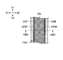
- FIGS. 8A to 8E are diagrams showing configuration examples of the first left V-groove 17AL.
- FIG. 8A is a top view of the first left V-groove 17AL before the first left optical fiber 3AL is installed.
- FIG. 8B is a top view of the first left V-groove 17AL after the first left optical fiber 3AL is installed.
- FIG. 8C is a view of the section including the section line VIIIC-VIIIC in FIG. 8B as viewed from the Y2 side as indicated by the arrow.
- FIG. 8D is a top view of the first left V-groove 17AL including another configuration example of the semi-cylindrical protrusion ST2.
- FIG. 8E is a top view of the first left V-groove 17AL including the hemispherical projection ST3, which is still another structural example of the stepped portion ST.
- the groove surface GS is given a rough dot pattern, and the step ST formed on the groove surface GS is given a fine dot pattern.
- the first left optical fiber 3AL is marked with a cross pattern for clarity.
- a contact portion CT which is a portion where the first left optical fiber 3AL and the first left V-groove 17AL contact each other, is indicated by a dashed line.
- step portion ST (semi-cylindrical projection ST2 or hemispherical projection ST3) formed in the first left V-groove 17AL, but the second left V-groove 17BL to the fourth left V-groove 17BL
- step ST formed in each of the left V-groove 17DL and the first right V-groove 17AR to the fourth right V-groove 17DR.
- FIGS. 8A to 8D show a semi-cylindrical projection ST2, which is still another example of the stepped portion ST.
- the semi-cylindrical projection ST2 includes a front semi-cylindrical projection ST2F formed on the front groove surface GSF of the first left V-groove 17AL and a rear semi-cylindrical projection ST2F formed on the rear groove surface GSB of the first left V-groove 17AL. and a protrusion ST2B.
- the front semi-cylindrical projection ST2F has a semi-circular cross section as shown in FIG. 8C, and is formed to extend continuously over the entire length of the first left V-groove 17AL as shown in FIG. 8A. The same applies to the rear semi-cylindrical projection ST2B.
- the support surface RF including the contact portion CT which is the portion where the first left optical fiber 3AL and the semi-cylindrical projection ST2 are in contact with each other, protrudes from the groove surface GS, thereby making it difficult for foreign matter to adhere to the support surface RF. have the effect of becoming This is because the surface area of the support surface RF is smaller than the surface area of the groove surface GS without the semi-cylindrical projections ST2.
- the semi-cylindrical projections ST2 may be intermittently arranged along the axial direction of the first left V-groove 17AL, as shown in FIG. 8D. Since this configuration can further reduce the surface area of the support surface RF, it is possible to further suppress foreign matter from adhering to the support surface RF.
- FIG. 8E shows a hemispherical projection ST3 that is still another example of the stepped portion ST.
- the hemispherical protrusion ST3 includes a front hemispherical protrusion ST3F formed on the front groove surface GSF of the first left V-groove 17AL and a rear hemispherical protrusion ST3B formed on the rear groove surface GSB of the first left V-groove 17AL. including. Since this configuration can further reduce the surface area of the support surface RF, it is possible to further suppress foreign matter from adhering to the support surface RF.
- the semi-cylindrical projection ST2 is formed to have a semi-circular cross-section, but the projection as the stepped portion ST may be semi-elliptical, triangular, square, or other shape. It may be formed to have a cross-sectional shape.
- the hemispherical projection ST3 is formed to have a semicircular cross section, but the projection as the stepped portion ST is formed to have another cross sectional shape such as a semielliptical, triangular, or quadrangular shape. may have been
- FIGS. 9A to 9C are diagrams showing configuration examples of the first left V-groove 17AL.
- FIG. 9A is a top view of the first left V-groove 17AL before the first left optical fiber 3AL is installed.
- FIG. 9B is a top view of the first left V-groove 17AL after the first left optical fiber 3AL is installed.
- FIG. 9C is a view of the section including the section line IXC-IXC in FIG. 9B as viewed from the Y2 side as indicated by the arrow.
- the groove surface GS has a rough dot pattern
- the stepped portion ST (hemispherical hole ST4) formed in the groove surface GS has a fine dot pattern.
- the first left optical fiber 3AL is marked with a cross pattern for clarity.
- a contact portion CT which is a portion where the first left optical fiber 3AL and the first left V-groove 17AL contact each other, is indicated by a dashed line.
- step portion ST (hemispherical hole ST4) formed in the first left V-groove 17AL, but the second left V-groove 17BL to the fourth left V-groove 17DL and the first left V-groove 17DL The same applies to the stepped portions ST formed in each of the right V-groove 17AR to the fourth right V-groove 17DR.
- FIGS. 9A to 9C show a hemispherical hole ST4, which is an example of the stepped portion ST.
- the hemispherical hole ST4 includes a front hemispherical hole ST4F formed in the front groove surface GSF of the first left V-groove 17AL and a rear hemispherical hole ST4B formed in the rear groove surface GSB of the first left V-groove 17AL.
- the front hemispherical hole ST4F is a recess formed in the front groove surface GSF so as to face the first left optical fiber 3AL installed in the first left V-groove 17AL. As shown, they are arranged at regular intervals along the extending direction (Y-axis direction) of the first left V-groove 17AL. The same applies to the rear hemispheric hole ST4B. However, both the front hemispherical hole ST4F and the rear hemispherical hole ST4B may be arranged at uneven intervals. In the example shown in FIG.
- the front hemispherical hole ST4F and the rear hemispherical hole ST4B are arranged so as to face each other in the X-axis direction, but they may be arranged so as not to face each other in the X-axis direction.
- the surface area of the contact portion CT which is the portion where the first left optical fiber 3AL and the groove surface GS of the first left V-groove 17AL contact each other, is smaller than in the case of the groove surface GS without the hemispherical hole ST4. Therefore, an effect that foreign matter is less likely to adhere to the contact portion CT is brought about.
- the hemispherical hole ST4 is formed to have a semicircular cross section, but the hole as the stepped portion ST may have other cross sectional shapes such as a semielliptical, triangular, or quadrangular shape. may be formed to have
- FIGS. 10A to 10C are diagrams showing configuration examples of the first left V-groove 17AL.
- FIG. 10A is a top view of the first left V-groove 17AL before the first left optical fiber 3AL is installed.
- FIG. 10B is a top view of the first left V-groove 17AL after the first left optical fiber 3AL is installed.
- FIG. 10C is a view of the cross section including the section line XC-XC in FIG. 10B as viewed from the Y2 side as indicated by the arrow.
- the groove surface GS is provided with a rough dot pattern, and the step ST (semi-cylindrical hole ST5) formed in the groove surface GS is provided with a fine dot pattern.
- a cross pattern is given to the first left optical fiber 3AL for clarity.
- the contact portion CT which is the portion where the first left optical fiber 3AL and the first left V-groove 17AL contact each other, is indicated by a dashed line.
- the contact portion CT constitutes the support surface RF.
- step portion ST (semi-cylindrical hole ST5) formed in the first left V-groove 17AL.
- stepped portion ST formed in each of the first right V-groove 17AR to the fourth right V-groove 17DR.
- FIGS. 10A to 10C show a semi-cylindrical hole ST5 which is an example of the step ST.
- the semi-cylindrical hole ST5 includes a front semi-cylindrical hole ST5F formed in the front groove surface GSF of the first left V-groove 17AL and a rear semi-cylindrical hole ST5F formed in the rear groove surface GSB of the first left V-groove 17AL. and hole ST5B.
- the front semi-cylindrical hole ST5F is, as shown in FIG. As shown in 10A, it is formed to extend continuously over the entire length of the first left V-groove 17AL. The same applies to the rear semi-cylindrical hole ST5B.
- the contact portion CT (support surface RF) where the first left optical fiber 3AL and the semi-cylindrical hole ST5 contact to the edge of the semi-cylindrical hole ST5
- the contact portion CT This provides an effect that foreign matter is less likely to adhere to the support surface (RF). This is because the surface area of the contact portion CT (support surface RF) is smaller than the surface area of the groove surface GS without the semi-cylindrical hole ST5.
- the semi-cylindrical hole ST5 is formed to have a semi-circular cross-section, but the hole as the step ST may be semi-elliptical, triangular, square, or other shape. It may be formed to have a cross-sectional shape.
- FIGS. 11A to 11C are diagrams showing configuration examples of the first left V-groove 17AL.
- FIG. 11A is a top view of the first left V-groove 17AL before the first left optical fiber 3AL is installed.
- FIG. 11B is a top view of the first left V-groove 17AL after the first left optical fiber 3AL is installed.
- FIG. 11C is a view of the section including the section line XIC-XIC in FIG. 11B as viewed from the Y2 side as indicated by the arrow.
- FIGS. 11A and 11B a rough dot pattern is added to the groove surface GS for clarity. Further, in FIG. 11A, for clarity, a fine dot pattern is added to the stepped portion ST (recessed portion ST6) formed on the groove surface GS. Also, in FIG. 11B, a cross pattern is given to the first left optical fiber 3AL for clarity. In addition, in FIGS. 11A and 11C, a contact portion CT, which is a portion where the first left optical fiber 3AL and the first left V-groove 17AL contact each other, is indicated by a dashed line.
- stepped portion ST recessed portion ST6 formed in the first left V-groove 17AL.
- stepped portions ST formed in each of the V-groove 17AR to the fourth right V-groove 17DR.
- FIGS. 11A to 11C show a recessed portion ST6, which is an example of the stepped portion ST.
- the recess ST6 is a portion that can temporarily store foreign matter, and is formed in the front recess ST6F formed in the front groove surface GSF of the first left V-groove 17AL and in the rear groove surface GSB of the first left V-groove 17AL. and a rear recess ST6B.
- the front recess ST6F is part of a recess provided at the bottom of the first left V-groove 17AL, and as shown in FIG. formed to extend. The same applies to the rear recess ST6B.
- this configuration by increasing the volume of the space provided at the bottom of the first left V-groove 17AL (the space capable of receiving foreign matter), the foreign matter deposited on the bottom of the first left V-groove 17AL is removed from the first left V-groove 17AL.
- This brings about the effect of being able to suppress contact with the fiber 3AL. That is, this configuration has the effect of suppressing the lifting of the first left optical fiber 3AL due to the foreign matter deposited on the bottom of the first left V-groove 17AL. And this structure brings about the effect that it can suppress that the contact of 1st left optical fiber 3AL and 1st left V-groove 17AL in contact part CT is obstructed.
- the recess ST6 is formed to have a rectangular cross section as shown in FIG. 11C, it may be formed to have another cross section such as trapezoidal, circular, or elliptical.
- FIGS. 12A to 12C are diagrams showing configuration examples of the first left V-groove 17AL.
- FIG. 12A is a top view of the first left V-groove 17AL before the first left optical fiber 3AL is installed.
- FIG. 12B is a view of the section including the section line XIIB-XIIB in FIG. 12A viewed from the Y2 side as indicated by the arrow.
- FIG. 12C is a top view of first left V-groove 17AL including round through hole ST8 that is another example of through hole ST7.
- FIGS. 12A and 12C a rough dot pattern is added to the groove surface GS for clarity.
- a contact portion CT which is a portion where the first left optical fiber 3AL and the first left V-groove 17AL contact each other, is indicated by a dashed line.
- step portion ST through hole ST7 or round through hole ST8 formed in the first left V-groove 17AL, but the second left V-groove 17BL to the fourth left V-groove 17BL
- stepped portion ST formed in each of the groove 17DL and the first right V-groove 17AR to the fourth right V-groove 17DR.
- FIGS. 12A and 12B show a through hole ST7, which is still another example of the stepped portion ST.
- the through hole ST7 includes a front recess ST7F formed in the front groove surface GSF of the first left V-groove 17AL and a rear recess ST7B formed in the rear groove surface GSB of the first left V-groove 17AL.
- the front concave portion ST7F is part of a rectangular through-hole provided in the bottom of the first left V-groove 17AL, and as shown in FIG. are formed to line up. The same applies to the rear recess ST7B.
- the through holes ST7 are arranged at equal intervals along the extending direction (Y-axis direction) of the first left V-groove 17AL.
- the through holes ST7 may be arranged at uneven intervals.
- This configuration has the effect of suppressing or preventing foreign matter from accumulating in the first left V-groove 17AL by providing the through hole ST7 at the bottom of the first left V-groove 17AL. That is, this configuration has the effect of preventing foreign matter from accumulating in the first left V-groove 17AL. Therefore, this configuration has the effect of suppressing the lifting of the first left optical fiber 3AL due to foreign matter deposited in the first left V-groove 17AL.
- This configuration has the effect of suppressing or preventing interference between the first left optical fiber 3AL and the first left V-groove 17AL at the contact portion CT. As a result, this configuration can reduce the frequency with which the position of the optical fiber installed in the V-groove is displaced from the predetermined position due to foreign matter, and as a result, additional work for removing foreign matter can be reduced. can.
- FIG. 12C shows a round through hole ST8 that is an example of the stepped portion ST.
- the through round hole ST8 includes a front concave portion ST8F formed in the front groove surface GSF of the first left V-groove 17AL and a rear concave portion ST8B formed in the rear groove surface GSB of the first left V-groove 17AL.
- the front recess ST8F is a part of the through round hole ST8 provided at the bottom of the first left V-groove 17AL, and is formed intermittently along the entire length of the first left V-groove 17AL as shown in FIG. 12C. It is The same applies to the rear recess ST8B. Further, in the example shown in FIG. 12c, the through round holes ST8 are arranged at regular intervals along the extending direction (Y-axis direction) of the first left V-groove 17AL. However, the through round holes ST8 may be arranged at uneven intervals.
- This configuration has the effect of suppressing or preventing foreign matter from accumulating in the first left V-groove 17AL by providing the round through hole ST8 at the bottom of the first left V-groove 17AL. That is, this configuration has the effect of suppressing the lifting of the first left optical fiber 3AL due to foreign matter deposited in the first left V-groove 17AL.
- This configuration has the effect of suppressing or preventing interference between the first left optical fiber 3AL and the first left V-groove 17AL at the contact portion CT. As a result, this configuration can reduce the frequency with which the position of the optical fiber installed in the V-groove is displaced from the predetermined position due to foreign matter, and as a result, additional work for removing foreign matter can be reduced. can.
- the fusion splicer 1 is configured to be able to fusion splice the first left optical fiber 3AL.
- the fusion splicer 1 includes a left base member 11L having a first left V-groove 17AL in which the first left optical fiber 3AL is installed.
- a step portion ST (holding guide ST1 in FIG. 6A or 6D, semi-cylindrical projection ST2 in FIG. 8A or 8D, semi-spherical projection in FIG. 8E) is provided on the inclined surface (groove surface GS) of the first left V-groove 17AL.
- ST3 the hemispherical hole ST4 in FIG. 9A, or the semi-cylindrical hole ST5 in FIG. 10A
- the stepped portion ST is provided at a position in contact with the first left optical fiber 3AL.
- This configuration reduces the surface area of the support surface RF including the contact portion CT, which is the portion of the groove surface GS of the first left V-groove 17AL with which the first left optical fiber 3AL contacts, thereby preventing foreign matter from entering the contact portion CT. can reduce the probability of adhesion. Therefore, this configuration prevents foreign objects from being caught between the first left optical fiber 3AL and the first left V-groove 17AL when the first left optical fiber 3AL is installed in the first left V-groove 17AL. It has the effect of suppressing This configuration has the effect that the first left optical fiber 3AL is accurately positioned within the first left V-groove 17AL.
- the support surface RF is typically a smaller (finer) surface than other portions of the groove surface GS so that the first left optical fiber 3AL can be positioned with high accuracy within the first left V-groove 17AL. It is configured to have roughness. Therefore, it may become difficult to peel off the foreign matter adhering to the support surface RF.
- the foreign matter is, for example, a substance (such as a residue of glass or a coating material) that has been vaporized by arc discharge during the previous fusion splicing and solidified after vaporization.
- the fusion splicer 1 can suppress or prevent foreign matter from adhering to the support surface RF for the reasons described above. Therefore, the fusion splicer 1 brings about an effect of realizing, for example, simplification or omission of cleaning of the first left optical fiber 3AL performed before fusion splicing. Similarly, the fusion splicer 1 brings about the effect of realizing, for example, simplification or omission of cleaning of the first left V-groove 17AL performed before fusion splicing. In addition, the fusion splicer 1 has the effect of suppressing or preventing breakage of the first left V-groove 17AL during cleaning of the first left V-groove 17AL.
- the groove surface GS which does not affect the positioning accuracy of the first left optical fiber 3AL, may be formed to have a larger (rougher) surface roughness than the support surface RF. This is for the purpose of forming at low cost. Also, this is to prevent foreign matter from adhering to the groove surface GS.
- the step ST may be a recess ST6 provided in the bottom of the first left V-groove 17AL, as shown in FIGS. It may be a through hole ST7 that penetrates. Alternatively, as shown in FIG. 12C, the stepped portion ST may be a through round hole ST8 penetrating through the left base member 11L.
- this configuration can suppress accumulation of foreign matter in the first left V-groove 17AL, it is possible to suppress or prevent the first left optical fiber 3AL from being lifted by the foreign matter accumulated in the first left V-groove 17AL. effect.
- This configuration also prevents foreign objects from being caught between the first left optical fiber 3AL and the first left V-groove 17AL when the first left optical fiber 3AL is installed in the first left V-groove 17AL. It brings about the effect of being able to suppress or prevent.
- This configuration has the effect that the first left optical fiber 3AL is accurately positioned within the first left V-groove 17AL. As a result, this configuration can reduce the frequency with which the position of the optical fiber installed in the V-groove is displaced from the predetermined position due to foreign matter, and as a result, additional work for removing foreign matter can be reduced. can.
- the step ST may be provided in at least one of the plurality of V-grooves (the first left V-groove 17AL to the fourth left V-groove 17DL). That is, the stepped portion ST may be provided in all of the plurality of V-grooves, or may be provided in only some of the plurality of V-grooves.
- the V-groove cleaning jig 70 used for cleaning the V-groove in the fusion splicer 1 is, as shown in FIG. It has a sliding surface 71 (central sliding surface 71MB and central sliding surface 71MF) in contact with the supporting surface RF (see FIG. 6B) that constitutes a part of the groove surface GS), and slides with the supporting surface RF It is configured to be slidable in the extending direction (Y-axis direction) of the first left V-groove 17AL while in contact with the surface 71 .
- This V-groove cleaning jig 70 can peel off foreign matter adhering to the support surface RF from the support surface RF before the first left optical fiber 3AL is installed in the first left V-groove 17AL. Therefore, when the first left optical fiber 3AL is installed in the first left V-groove 17AL, foreign matter can be prevented from being caught between the first left optical fiber 3AL and the first left V-groove 17AL. bring. Then, the jig 70 brings about the effect that the first left optical fiber 3AL is accurately positioned in the first left V-groove 17AL.
- the fusion splicer 1 includes the left base member 11L formed with a plurality of V-grooves and the right base member 11R formed with a plurality of V-grooves.
- the fusion splicer 1 may include the left base member 11L having only one V-groove and the right base member 11R having only one V-groove.
- Each V groove may be provided with a step portion ST. That is, the fusion splicer 1 may be a device for fusion splicing a single optical fiber.
- the shape of the jig 70 shown in FIGS. 7A to 7D is configured to conform to the shape of the V-groove shown in FIG. 6B. It may be configured to fit other V-groove shapes.
- V groove group 17A First V groove pair 17AL First left V groove 17AR First right V groove 17B Second V groove pair 17BL Second left V groove 17BR Second right V groove 17C Third V groove pair 17CL Third left V groove 17CR Third right V groove 17D Fourth V groove pair 17DL Fourth left V groove 17DR Fourth right V groove 17L Left V groove group 17R Right V groove group 21 Clamp 21L Left clamp 21La Left arm portion 21Lb... Left pressing part 21R... Right clamp 21Ra... Right arm part 21Rb... Right pressing part 31... Fiber holder 31L... Left fiber holder 31La... Left fiber holder body 31Lb.
Landscapes
- Physics & Mathematics (AREA)
- General Physics & Mathematics (AREA)
- Optics & Photonics (AREA)
- Engineering & Computer Science (AREA)
- Plasma & Fusion (AREA)
- Chemical & Material Sciences (AREA)
- Crystallography & Structural Chemistry (AREA)
- Mechanical Coupling Of Light Guides (AREA)
Priority Applications (4)
| Application Number | Priority Date | Filing Date | Title |
|---|---|---|---|
| CN202280036961.0A CN117377897A (zh) | 2021-06-29 | 2022-06-23 | 熔接机和v形槽清扫用工具 |
| KR1020237041364A KR20240023509A (ko) | 2021-06-29 | 2022-06-23 | 융착 접속기 및 v홈 청소용 지그 |
| US18/561,486 US20240248257A1 (en) | 2021-06-29 | 2022-06-23 | Fusion splicer and v groove cleaning jig |
| JP2023531881A JPWO2023276852A1 (https=) | 2021-06-29 | 2022-06-23 |
Applications Claiming Priority (2)
| Application Number | Priority Date | Filing Date | Title |
|---|---|---|---|
| JP2021-107911 | 2021-06-29 | ||
| JP2021107911 | 2021-06-29 |
Publications (1)
| Publication Number | Publication Date |
|---|---|
| WO2023276852A1 true WO2023276852A1 (ja) | 2023-01-05 |
Family
ID=84691307
Family Applications (1)
| Application Number | Title | Priority Date | Filing Date |
|---|---|---|---|
| PCT/JP2022/025135 Ceased WO2023276852A1 (ja) | 2021-06-29 | 2022-06-23 | 融着接続機及びv溝清掃用治具 |
Country Status (5)
| Country | Link |
|---|---|
| US (1) | US20240248257A1 (https=) |
| JP (1) | JPWO2023276852A1 (https=) |
| KR (1) | KR20240023509A (https=) |
| CN (1) | CN117377897A (https=) |
| WO (1) | WO2023276852A1 (https=) |
Families Citing this family (1)
| Publication number | Priority date | Publication date | Assignee | Title |
|---|---|---|---|---|
| JP1740469S (ja) * | 2022-11-15 | 2023-03-30 | 光ファイバ整列部材 |
Citations (5)
| Publication number | Priority date | Publication date | Assignee | Title |
|---|---|---|---|---|
| JPH05224070A (ja) * | 1992-02-14 | 1993-09-03 | Fujikura Ltd | 光ファイバ接続装置に於けるファイバ軸合わせブロック体のv溝清掃具 |
| JPH0743548A (ja) * | 1993-07-29 | 1995-02-14 | Sumitomo Electric Ind Ltd | 光ファイバの調心装置 |
| JP2015129925A (ja) * | 2013-12-04 | 2015-07-16 | 株式会社成和技研 | 融着機 |
| US20190346627A1 (en) * | 2016-12-05 | 2019-11-14 | Commscope Technologies Llc | Multi-fiber ferrule-less duplex fiber optic connectors with multi-fiber alignment devices |
| WO2020162044A1 (ja) * | 2019-02-06 | 2020-08-13 | Seiオプティフロンティア株式会社 | 光ファイバの融着接続方法及び融着接続装置 |
Family Cites Families (1)
| Publication number | Priority date | Publication date | Assignee | Title |
|---|---|---|---|---|
| US6874950B2 (en) * | 2002-12-17 | 2005-04-05 | International Business Machines Corporation | Devices and methods for side-coupling optical fibers to optoelectronic components |
-
2022
- 2022-06-23 JP JP2023531881A patent/JPWO2023276852A1/ja active Pending
- 2022-06-23 US US18/561,486 patent/US20240248257A1/en active Pending
- 2022-06-23 WO PCT/JP2022/025135 patent/WO2023276852A1/ja not_active Ceased
- 2022-06-23 KR KR1020237041364A patent/KR20240023509A/ko not_active Withdrawn
- 2022-06-23 CN CN202280036961.0A patent/CN117377897A/zh not_active Withdrawn
Patent Citations (5)
| Publication number | Priority date | Publication date | Assignee | Title |
|---|---|---|---|---|
| JPH05224070A (ja) * | 1992-02-14 | 1993-09-03 | Fujikura Ltd | 光ファイバ接続装置に於けるファイバ軸合わせブロック体のv溝清掃具 |
| JPH0743548A (ja) * | 1993-07-29 | 1995-02-14 | Sumitomo Electric Ind Ltd | 光ファイバの調心装置 |
| JP2015129925A (ja) * | 2013-12-04 | 2015-07-16 | 株式会社成和技研 | 融着機 |
| US20190346627A1 (en) * | 2016-12-05 | 2019-11-14 | Commscope Technologies Llc | Multi-fiber ferrule-less duplex fiber optic connectors with multi-fiber alignment devices |
| WO2020162044A1 (ja) * | 2019-02-06 | 2020-08-13 | Seiオプティフロンティア株式会社 | 光ファイバの融着接続方法及び融着接続装置 |
Also Published As
| Publication number | Publication date |
|---|---|
| US20240248257A1 (en) | 2024-07-25 |
| JPWO2023276852A1 (https=) | 2023-01-05 |
| CN117377897A (zh) | 2024-01-09 |
| KR20240023509A (ko) | 2024-02-22 |
Similar Documents
| Publication | Publication Date | Title |
|---|---|---|
| US12276841B2 (en) | Optical fiber fusion splicing method and fusion splicing device | |
| JP4682496B2 (ja) | 融着接続装置 | |
| WO2023276852A1 (ja) | 融着接続機及びv溝清掃用治具 | |
| JP6712869B2 (ja) | ベース部材および融着機 | |
| US20240280753A1 (en) | Fusion splicer, and method for connecting optical fiber | |
| CN118355303A (zh) | 熔接机 | |
| EP3923049B1 (en) | Fusion splicing device and fusion splicing method | |
| JP2003014974A (ja) | 光ファイバ融着接続装置の光ファイバ保持機構 | |
| JP6839654B2 (ja) | 光ファイバ保持部材、融着機 | |
| JP5144817B2 (ja) | ファイバークランプ機構 | |
| EP4339667A1 (en) | Fusion splice machine | |
| WO2023112910A1 (ja) | 融着接続機 | |
| US9753233B2 (en) | Method and apparatus for making an optical fiber array | |
| US11237330B2 (en) | Optical fiber alignment jig, optical fiber fusion splicer equipped with optical fiber alignment jig, and method for aligning optical fiber | |
| CN111123433B (zh) | 用于特种光纤的切割装置配件、切割装置及光纤切割方法 | |
| JP7110553B2 (ja) | レンズ付き光ファイバの製造方法、及び切断装置 | |
| JP2007279291A (ja) | 光ファイバ構造体及びその製造装置、並びに、それに用いられるブロック状チップ | |
| CN121443984A (zh) | 光纤的熔接方法和光纤的熔接装置 | |
| WO2024122648A1 (en) | Optical fiber cutting device and optical fiber cutting method | |
| WO2023085332A1 (ja) | 光ファイバの融着接続方法、及び、光ファイバの融着接続装置 | |
| JP2016057531A (ja) | 光コネクタ部品の製造方法 | |
| JP2007248522A (ja) | ファイバコリメータの製造方法および光ファイバ保持台 | |
| WO2014065922A2 (en) | Binding material processing of gradient index (grin) rods into grin lenses attachable to optical devices, components, and methods |
Legal Events
| Date | Code | Title | Description |
|---|---|---|---|
| 121 | Ep: the epo has been informed by wipo that ep was designated in this application |
Ref document number: 22832999 Country of ref document: EP Kind code of ref document: A1 |
|
| WWE | Wipo information: entry into national phase |
Ref document number: 18561486 Country of ref document: US |
|
| WWE | Wipo information: entry into national phase |
Ref document number: 202280036961.0 Country of ref document: CN |
|
| WWE | Wipo information: entry into national phase |
Ref document number: 2023531881 Country of ref document: JP |
|
| NENP | Non-entry into the national phase |
Ref country code: DE |
|
| 122 | Ep: pct application non-entry in european phase |
Ref document number: 22832999 Country of ref document: EP Kind code of ref document: A1 |
|
| WWW | Wipo information: withdrawn in national office |
Ref document number: 1020237041364 Country of ref document: KR |