WO2023276825A1 - 物体検出装置 - Google Patents
物体検出装置 Download PDFInfo
- Publication number
- WO2023276825A1 WO2023276825A1 PCT/JP2022/024915 JP2022024915W WO2023276825A1 WO 2023276825 A1 WO2023276825 A1 WO 2023276825A1 JP 2022024915 W JP2022024915 W JP 2022024915W WO 2023276825 A1 WO2023276825 A1 WO 2023276825A1
- Authority
- WO
- WIPO (PCT)
- Prior art keywords
- time limit
- threshold
- object detection
- wave
- transmission
- Prior art date
Links
- 238000001514 detection method Methods 0.000 title claims abstract description 97
- 230000005540 biological transmission Effects 0.000 claims abstract description 66
- 230000008859 change Effects 0.000 claims description 8
- 238000010586 diagram Methods 0.000 description 13
- 238000000034 method Methods 0.000 description 13
- 230000004048 modification Effects 0.000 description 8
- 238000012986 modification Methods 0.000 description 8
- 238000012545 processing Methods 0.000 description 6
- 230000008569 process Effects 0.000 description 5
- 230000007257 malfunction Effects 0.000 description 4
- 238000002366 time-of-flight method Methods 0.000 description 4
- 238000005516 engineering process Methods 0.000 description 3
- 230000006870 function Effects 0.000 description 3
- 238000004590 computer program Methods 0.000 description 2
- 238000005259 measurement Methods 0.000 description 2
- 230000002123 temporal effect Effects 0.000 description 2
- 230000002238 attenuated effect Effects 0.000 description 1
- 238000004891 communication Methods 0.000 description 1
- 230000006866 deterioration Effects 0.000 description 1
- 230000000694 effects Effects 0.000 description 1
- 230000004044 response Effects 0.000 description 1
- 230000035945 sensitivity Effects 0.000 description 1
- 239000007787 solid Substances 0.000 description 1
Images


Classifications
-
- G—PHYSICS
- G01—MEASURING; TESTING
- G01S—RADIO DIRECTION-FINDING; RADIO NAVIGATION; DETERMINING DISTANCE OR VELOCITY BY USE OF RADIO WAVES; LOCATING OR PRESENCE-DETECTING BY USE OF THE REFLECTION OR RERADIATION OF RADIO WAVES; ANALOGOUS ARRANGEMENTS USING OTHER WAVES
- G01S15/00—Systems using the reflection or reradiation of acoustic waves, e.g. sonar systems
- G01S15/88—Sonar systems specially adapted for specific applications
- G01S15/93—Sonar systems specially adapted for specific applications for anti-collision purposes
- G01S15/931—Sonar systems specially adapted for specific applications for anti-collision purposes of land vehicles
-
- G—PHYSICS
- G01—MEASURING; TESTING
- G01S—RADIO DIRECTION-FINDING; RADIO NAVIGATION; DETERMINING DISTANCE OR VELOCITY BY USE OF RADIO WAVES; LOCATING OR PRESENCE-DETECTING BY USE OF THE REFLECTION OR RERADIATION OF RADIO WAVES; ANALOGOUS ARRANGEMENTS USING OTHER WAVES
- G01S7/00—Details of systems according to groups G01S13/00, G01S15/00, G01S17/00
- G01S7/52—Details of systems according to groups G01S13/00, G01S15/00, G01S17/00 of systems according to group G01S15/00
- G01S7/523—Details of pulse systems
- G01S7/526—Receivers
Definitions
- the present invention relates to an object detection device.
- information about an object is obtained by transmitting a transmitted wave and receiving a received wave (reflected wave) as a transmitted wave that has been reflected back from an object using an ultrasonic sensor.
- Techniques for detection are known.
- Patent Document 1 by switching the object detection threshold according to the reverberation beat state that appears when foreign matter adheres to the surface of the ultrasonic sensor, the object detection performance is less likely to deteriorate even if the sensitivity is lowered due to the adhesion of foreign matter. Techniques are disclosed.
- the present invention has been made in view of the above, and provides an object detection device that performs appropriate object detection without being affected by outside temperature.
- the object detection device of the present invention includes, for example, a transmission unit that transmits a transmission wave and a reception wave as the transmission wave that is returned by being reflected by an object.
- a temperature sensor for measuring the surrounding outside air temperature, and a time limit for detecting that the degree of vibration after the transmission by the transmitting part falls below the reverberation threshold, the outside temperature measured by the temperature sensor and a time limit for detecting that the degree of vibration after transmission is below the reverberation threshold set by the threshold time limit setting unit, and based on the reflected wave received by the receiving unit and an object detection unit that detects an object present in the surroundings.
- the object detection device described above even if the reverberation time is extended at low temperatures, the detection cycle delay in normal detection does not occur, and the degree of vibration after transmission is reliably below the reverberation threshold. Since it becomes possible to detect, it can be realized to perform proper object detection.
- the threshold time limit setting unit determines whether to change the time limit in a situation where the system operation for object detection does not occur. According to such a configuration, it is possible to avoid malfunction caused by switching the time limit during the operation of the object detection system.
- the threshold time limit setting unit determines whether to change the time limit in a situation where the vehicle is stopped due to the shift of the vehicle being in parking. According to such a configuration, it is possible to avoid malfunction caused by switching the time limit during the operation of the object detection system.
- the threshold time limit setting unit determines whether to change the time limit in a situation where the vehicle is stopped due to the vehicle's brake being stepped on. According to such a configuration, it is possible to avoid malfunction caused by switching the time limit during the operation of the object detection system.
- the threshold time limit setting unit determines that the outside temperature is equal to or less than the threshold value
- the time limit is switched to a second time limit longer than the first time limit for normal use. According to such a configuration, even if the reverberation time is extended at low temperature, the detection cycle delay in normal detection does not occur, and it is reliably detected that the degree of vibration after transmission is below the threshold. Therefore, it is possible to perform proper object detection.
- FIG. 1 is an exemplary schematic diagram showing the appearance of a vehicle equipped with an object detection system according to an embodiment, viewed from above.
- FIG. 2 is an exemplary schematic block diagram showing the hardware configuration of the object detection system according to the embodiment; 3A and 3B are exemplary and schematic diagrams for explaining an outline of a technique used by the object detection device according to the embodiment to detect a distance to an object;
- FIG. FIG. 4 is a diagram showing an example of an event when the reverberation time is extended at low temperature.
- FIG. 5 is a functional block diagram of the functional configuration of the object detection device according to the embodiment;
- FIG. 6 is an exemplary flowchart illustrating the flow of processing executed by the threshold expiration date setting unit of the object detection device according to the embodiment;
- FIG. 7 is a diagram showing an example of switching the time limit at low temperature.
- FIG. 1 is an exemplary schematic diagram showing the appearance of a vehicle 1 equipped with an object detection device according to an embodiment, viewed from above.
- the object detection apparatus transmits and receives sound waves (ultrasonic waves), and acquires the time difference between the transmission and reception, thereby detecting objects including humans existing in the surroundings (e.g. 2 is an in-vehicle sensor system that detects information about an obstacle O) shown in FIG.
- the object detection system includes an ECU (Electronic Control Unit) 100 as an in-vehicle control device and object detection devices 201 to 204 as in-vehicle sonars. ing.
- the ECU 100 is mounted inside a four-wheeled vehicle 1 including a pair of front wheels 3F and a pair of rear wheels 3R.
- the object detection devices 201 to 204 are installed at different positions in the rear end portion (rear bumper) of the vehicle body 2 as the exterior of the vehicle 1. 204 are not limited to the example shown in FIG.
- the object detection devices 201 to 204 may be installed at the front end (front bumper) of the vehicle body 2, may be installed at the side of the vehicle body 2, or may be installed at the rear end, the front end, and the side surface. may be installed in two or more of
- the hardware configurations and functions of the object detection devices 201 to 204 are the same. Therefore, hereinafter, the object detection devices 201 to 204 may be collectively referred to as the object detection device 200 for simplification. Also, in the embodiment, the number of object detection devices 200 is not limited to four as shown in FIG.
- FIG. 2 is an exemplary and schematic block diagram showing the hardware configuration of the object detection system according to the embodiment.
- the ECU 100 has a hardware configuration similar to that of a normal computer. More specifically, the ECU 100 includes an input/output device 110 , a storage device 120 and a processor 130 .
- the input/output device 110 is an interface for realizing transmission and reception of information between the ECU 100 and the outside.
- communication partners of ECU 100 are object detection device 200 and temperature sensor 50 .
- a temperature sensor 50 is mounted on the vehicle 1 to measure the outside air temperature around the vehicle 1 .
- the storage device 120 includes main storage devices such as ROM (Read Only Memory) and RAM (Random Access Memory), and/or auxiliary storage devices such as HDD (Hard Disk Drive) and SSD (Solid State Drive). .
- main storage devices such as ROM (Read Only Memory) and RAM (Random Access Memory)
- auxiliary storage devices such as HDD (Hard Disk Drive) and SSD (Solid State Drive).
- the processor 130 controls various processes executed in the ECU 100.
- Processor 130 includes an arithmetic unit such as a CPU (Central Processing Unit).
- Processor 130 reads and executes computer programs stored in storage device 120 to implement various functions such as automatic parking.
- the object detection device 200 includes a transducer 210 and a control section 220.
- the wave transmitter/receiver 210 has a transducer 211 configured by a piezoelectric element or the like, and the transducer 211 transmits and receives ultrasonic waves.
- the transducer 210 transmits an ultrasonic wave generated in response to vibration of the transducer 211 as a transmission wave, and the ultrasonic wave transmitted as the transmission wave is reflected by an external object and returned. Vibration of the vibrator 211 brought about by coming is received as a reception wave.
- an obstacle O placed on the road surface RS is illustrated as an object that reflects ultrasonic waves from the transducer 210 .
- FIG. 2 illustrates a configuration in which both transmission of transmission waves and reception of received waves are realized by a single transducer 210 having a single transducer 211 .
- the technique of the embodiment is different from the configuration of the transmitting side, such as a configuration in which a first transducer for transmitting transmission waves and a second transducer for receiving reception waves are separately provided. It can also be applied to a configuration in which the receiving side configuration is separated.
- the control unit 220 has the same hardware configuration as a normal computer. More specifically, the controller 220 includes an input/output device 221 , a storage device 222 and a processor 223 .
- the input/output device 221 is an interface for realizing transmission and reception of information between the control unit 220 and the outside (the ECU 100 and the transducer 210 in the example shown in FIG. 1).
- the storage device 222 includes main storage such as ROM and RAM, and auxiliary storage such as HDD or SSD.
- the processor 223 controls various processes executed by the control unit 220 .
- Processor 223 includes an arithmetic unit such as a CPU, for example.
- the processor 223 implements various functions by reading and executing computer programs stored in the storage device 333 .
- the object detection device 200 detects the distance to the object using a technique called the TOF (Time Of Flight) method.
- the TOF method considers the difference between the timing at which the transmission wave is transmitted (more specifically, the transmission has started) and the timing at which the reception wave has been received (more specifically, the reception has started). , is a technique for calculating the distance to an object.
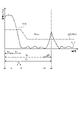
- FIG. 3 is an exemplary and schematic diagram for explaining an overview of the technique used by the object detection device 200 according to the embodiment to detect the distance to an object.
- FIG. 3 is an exemplary and schematic diagram showing temporal changes in the signal level (for example, amplitude) of ultrasonic waves transmitted and received by the object detection apparatus 200 according to the embodiment.
- the horizontal axis corresponds to time
- the vertical axis corresponds to the signal level of the signal transmitted and received by the object detection device 200 via the transducer 210 (vibrator 211).
- a solid line L11 represents an example of an envelope representing the signal level of the signal transmitted and received by the object detection device 200, that is, the temporal change in the degree of vibration of the transducer 211. From this solid line L11, the oscillator 211 is driven and oscillated for the time Ta from timing t0, and the transmission of the transmission wave is completed at timing t1. It can be read that the vibration of the vibrator 211 continues while attenuating. Therefore, in the graph shown in FIG. 3, time Tb corresponds to so-called reverberation time.
- the solid line L11 indicates that the degree of vibration of the transducer 211 exceeds (or exceeds) a predetermined threshold value Th1 represented by the dashed-dotted line L21 at timing t4, which is the time Tp after the timing t0 at which transmission of the transmission wave is started. ) peak.
- This threshold Th1 is caused by reception of a received wave (reflected wave) as a transmitted wave that has been reflected back by an object to be detected (for example, an obstacle O shown in FIG. 2). or caused by receiving a received wave (reflected wave) as a transmitted wave that has been reflected back by an object other than the specimen (for example, the road surface RS shown in FIG. 2). It is a preset value for
- the threshold Th1 is the reverberation time end determination, that is, the reverberation threshold Th1a used for the start determination when acquiring the received wave (reflected wave) as the reflected and returned transmitted wave, and the reflected and returned transmitted wave
- the control unit 220 determines that the reverberation time has ended when a predetermined delay time Ty elapses after the degree of vibration after wave transmission falls below the reverberation threshold value Th1a. (Timing t2), reading of a received wave (reflected wave) as a reflected transmitted wave is started.
- the time limit (Ta+Tb) for detecting that the degree of vibration after transmission falls below the reverberation threshold Th1a (the length of the reverberation threshold Th1a when reverberation is not detected) is defined in advance.
- the control unit 220 determines that the reverberation time has ended, it proceeds to start reading the received wave (reflected wave) as the transmitted wave that has been reflected back.
- the control unit 220 switches the threshold Th1 from the reverberation threshold Th1a to the reflected wave threshold Th1b as the reading of the received wave (reflected wave) as the transmitted wave that has been reflected back is started. is used for object detection.
- the threshold Th1 is gradually lowered from the reverberation threshold Th1a to the reflected wave threshold Th1b, and then kept constant at the reflected wave threshold Th1b.
- control unit 220 compares the degree of vibration of the reflected wave with the reflected wave threshold value Th1b, and determines that an object has been detected based on whether the degree of vibration of the reflected wave exceeds the reflected wave threshold value Th1b. .
- the vibration having a peak exceeding (or more than) the threshold Th1 (reflected wave threshold Th1b) is also caused by receiving a received wave (reflected wave) as a transmitted wave that has been reflected back by the object to be detected. It can be regarded as a given.
- vibrations having a peak below (or less than) the threshold Th1 (reflected wave threshold Th1b) are caused by receiving a received wave (reflected wave) as a transmitted wave that has been reflected back by an object outside the detection target. can be considered to have been
- the vibration of the transducer 211 at timing t4 was caused by the reception of the received wave (reflected wave) as the transmitted wave that was reflected back by the object to be detected. can be read.
- the timing t4 is the timing when the received wave (reflected wave) as the transmitted wave that has been reflected back by the object to be detected has been completely received. It corresponds to the timing of returning as (reflected wave).
- the timing t3 as the starting point of the peak at the timing t4 is the timing at which the reception of the received wave (reflected wave) as the transmitted wave that has been reflected back by the object to be detected starts to be received. For example, it corresponds to the timing at which the transmission wave first transmitted at timing t0 returns as a reception wave (reflected wave). Therefore, on the solid line L11, the time ⁇ T between the timing t3 and the timing t4 is equal to the time Ta as the transmission time of the transmission wave.
- the time Tf between the timing t0 when the transmission wave starts to be transmitted and the timing t3 when the reception wave starts to be received is obtained. is required.
- This time Tf is calculated from time Tp as the difference between timing t0 and timing t4 at which the signal level of the received wave reaches a peak exceeding the threshold Th1 (reflected wave threshold Th1b), and time Ta as the transmission time of the transmitted wave. can be obtained by subtracting a time ⁇ T equal to .
- the timing t0 when the transmission wave starts to be transmitted can be easily identified as the timing when the object detection device 200 starts operating, and the time Ta as the transmission time of the transmission wave is predetermined by setting or the like. Therefore, in order to obtain the distance to the object to be detected by the TOF method, it is important to specify the timing t4 when the signal level of the received wave peaks over the threshold Th1 (reflected wave threshold Th1b). becomes. In order to specify the timing t4, it is important to accurately detect the correspondence between the transmitted wave and the received wave (reflected wave) as the transmitted wave that is reflected back by the object to be detected. becomes.
- the transducer 210 that transmits and receives ultrasonic waves has temperature characteristics. Therefore, it is known that the transducer 210 has a longer reverberation time at low temperatures than at room temperature. When the reverberation time is extended at low temperatures, the following problems arise.
- FIG. 4 is a diagram showing an example of an event when the reverberation time is extended at low temperatures.
- the time limit (Ta+Tb) for detecting that the degree of vibration after wave transmission falls below the reverberation threshold Th1a is exceeded.
- Detection period delay in normal detection occurs, such as being unable to detect that the degree of vibration falls below the reverberation threshold Th1a, or delaying the timing of detecting that the degree of vibration after transmission falls below the reverberation threshold Th1a.
- Detection period delay in normal detection occurs, such as being unable to detect that the degree of vibration falls below the reverberation threshold Th1a, or delaying the timing of detecting that the degree of vibration after transmission falls below the reverberation threshold Th1a.
- the object detection device 200 by configuring the object detection device 200 as follows, even when the reverberation time is extended at low temperature, the degree of vibration after transmitting the wave is less than the reverberation threshold Th1a. To enable reliable detection and to execute appropriate object detection.
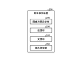
- FIG. 5 is a functional block diagram showing the functional configuration of the object detection device 200 according to the embodiment.
- the object detection device 200 includes a transmission section 230 , a reception section 240 , a threshold deadline setting section 250 and a detection processing section 260 .
- the transmission unit 230 transmits transmission waves to the outside by vibrating the above-described transducer 211 at predetermined transmission intervals.
- a transmission interval is a time interval from when a transmission wave is transmitted to when the next transmission wave is transmitted.
- the transmitter 230 includes, for example, a circuit that generates a carrier wave, a circuit that generates a pulse signal corresponding to identification information to be given to the carrier wave, a multiplier that modulates the carrier wave according to the pulse signal, and a transmission output from the multiplier. It is configured using an amplifier or the like that amplifies a signal.
- the receiving section 240 receives a received wave as a reflected wave of the transmitted wave transmitted from the transmitting section 230 until a predetermined measurement time elapses after the transmission wave is transmitted.
- the measurement time is a waiting time set for receiving a reception wave as a reflected wave of the transmission wave after transmission of the transmission wave.
- the threshold time limit setting unit 250 varies the time limit (Ta+Tb) for detecting that the degree of vibration after wave transmission falls below the reverberation threshold Th1a based on the outside air temperature around the vehicle 1 measured by the temperature sensor 50. set to More specifically, the threshold time limit setting unit 250 sets the first time limit as the time limit when the outside air temperature around the vehicle 1 is normal. Further, when the outside air temperature around the vehicle 1 is in a state of low temperature, a second time limit longer than the first time limit (first time limit ⁇ second time limit) is set as the time limit. set.
- the threshold time limit setting unit 250 may variably set the delay time Ty based on the outside air temperature around the vehicle 1 measured by the temperature sensor 50 .
- the reflected wave is generated earlier by the extension of the time limit (Ta+Tb) for detecting that the degree of vibration after transmission is below the reverberation threshold Th1a. It is desirable to move to the start of reading of Therefore, the threshold time limit setting unit 250 may set the delay time Ty short when the outside air temperature around the vehicle 1 is low. This avoids erroneous detection of an object based on the ambient temperature around the vehicle 1, while ensuring detection performance for short-distance objects.
- the detection processing unit 260 follows the time limit (Ta+Tb) for detecting that the degree of vibration after transmission is below the reverberation threshold Th1a set by the threshold period setting unit 250, and the reflection received by the receiving unit 240 is Based on the waves, the TOF method detects the distance to the object.
- At least part of the configuration shown in FIG. 5 is the result of cooperation between hardware and software. is implemented as a result of reading and executing
- at least part of the configuration shown in FIG. 5 may be realized by dedicated hardware (circuitry).
- each configuration shown in FIG. 5 may operate under the control of the control unit 220 of the object detection device 200 itself, or may operate under the control of the external ECU 100. good.
- the threshold time limit setting unit 250 of the object detection device 200 executes processing according to the flow shown in FIG. Switch the time limit of the time (Ta+Tb) for detecting falling below Th1a.
- FIG. 6 is an exemplary flowchart showing the flow of processing executed by the threshold deadline setting unit 250 of the object detection device 200 according to the embodiment.
- the threshold time limit setting unit 250 of the object detection device 200 acquires vehicle information of the vehicle 1 from the ECU 100 (step S1).
- the vehicle information acquired from the ECU 100 includes, for example, shift information and vehicle speed information.
- the threshold time limit setting unit 250 of the object detection device 200 acquires the outside air temperature around the vehicle 1 measured by the temperature sensor 50 (step S2).
- the threshold time limit setting unit 250 of the object detection device 200 determines whether the vehicle 1 is stopped based on the vehicle information of the vehicle 1 (step S3).
- whether or not the vehicle 1 is stopped is determined by the time (Ta+Tb) for detecting that the degree of vibration after transmission is below the reverberation threshold Th1a in a situation where the system operation for object detection does not occur. This is because it is necessary to switch the time limit.
- a situation in which the system operation for object detection does not occur is a situation in which the vehicle 1 is stopped because the shift of the vehicle 1 is in P (parking), and a situation in which the vehicle 1 stops because the brake of the vehicle 1 is applied. Such as when the vehicle is parked.
- a situation in which the vehicle 1 is in P (parking) and the vehicle 1 is stopped can be determined from shift information or the like as vehicle information acquired from the ECU 100 .
- a situation in which the vehicle 1 is stopped because the brakes of the vehicle 1 are stepped on can be determined from vehicle speed information or the like as vehicle information acquired from the ECU 100 . By doing so, it is possible to avoid the occurrence of malfunction due to switching of the time limit during the operation of the object detection system.
- the threshold time limit setting unit 250 of the object detection device 200 determines that the vehicle 1 is not stopped (No in step S3), it means that the object detection system is operating, so the process ends.
- the threshold time limit setting unit 250 of the object detection device 200 determines that the vehicle 1 is not stopped (Yes in step S3), it determines whether the outside temperature is equal to or less than the threshold (step S4).
- the threshold value of the outside air temperature is assumed to be zero degrees, for example.
- the threshold time limit setting unit 250 of the object detection device 200 determines that the outside air temperature is equal to or lower than the threshold (zero degrees) (Yes in step S4), it detects that the degree of vibration after transmission is below the reverberation threshold Th1a.
- the time limit of time (Ta+Tb) is switched to the second time limit for low temperature (step S5), and the process ends.
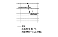
- FIG. 7 is a diagram showing an example of switching the time limit at low temperatures.
- the threshold time limit setting unit 250 of the object detection device 200 detects that the degree of vibration after transmission is below the reverberation threshold Th1a.
- the time limit of the time (Ta+Tb) for normal use is switched to a second time limit longer than the first time limit for normal use.
- the threshold time period setting unit 250 of the object detection device 200 determines that the outside air temperature is not equal to or lower than the threshold (zero degrees) (No in step S4), it detects that the degree of vibration after transmission is below the reverberation threshold Th1a.
- the time limit for the time (Ta+Tb) to be set is switched to the first time limit for normal use (step S6), and the process is terminated.
- the object detection device 200 includes the threshold deadline setting unit 250.
- the threshold time limit setting unit 250 sets the time limit (Ta+Tb) for detecting that the degree of vibration after transmission falls below the reverberation threshold Th1a. In some cases, it should be longer than usual. As a result, even when the reverberation time is extended at low temperatures, it is possible to reliably detect that the degree of vibration after transmission is below the reverberation threshold Th1a without causing a detection period delay in normal detection. Therefore, it is realized to perform proper object detection.
- the object detection device 200 at room temperature, it is possible to shorten the time limit (Ta+Tb) for detecting that the degree of vibration after wave transmission falls below the reverberation threshold Th1a. , it is possible to improve the object detection performance at a short distance at room temperature.
- the technology of the present disclosure is applied to a configuration that detects information about an object by transmitting and receiving ultrasonic waves. It can also be applied to a configuration in which information about an object is detected by transmitting and receiving waves and other waves such as electromagnetic waves.
- an object detection device that detects the distance to an object is exemplified. It can also be applied to an object detection device that detects
- the time limit (Ta+Tb) for detecting that the outside temperature falls below the reverberation threshold Th1a is switched to a second time limit longer than the first time limit for normal use.
- the time limit for the outside air temperature it is also possible to finely change the time limit.
Abstract
Description
図1は、実施形態にかかる物体検出装置を備えた車両1を上方から見た外観を示した例示的かつ模式的な図である。
なお、上述した実施形態では、本開示の技術が、超音波の送受信によって物体に関する情報を検知する構成に適用されているが、本開示の技術は、超音波以外の波動としての、音波、ミリ波、および電磁波などの他の波動の送受信によって物体に関する情報を検知する構成にも適用することが可能である。
50 温度センサ
200 物体検出装置
230 送信部
240 受信部
250 閾値制限設定部
260 物体検出部
Claims (5)
- 送信波を送信する送信部と、
物体での反射により戻ってきた前記送信波としての受信波を受信する受信部と、
周囲の外気温を測定する温度センサと、
前記送信部による送波後の振動の度合が残響閾値を下回ることを検知する時間の制限時間を、前記温度センサで測定した外気温によって変更する閾値期限設定部と、
前記閾値期限設定部により設定された送波後の振動の度合が残響閾値を下回ることを検知する時間の制限時間に従い、前記受信部で受信した反射波に基づいて、周囲に存在する物体を検出する物体検出部と、
を備えることを特徴とする物体検出装置。 - 前記閾値期限設定部は、物体検出のシステム作動が発生しない状況において、前記制限時間の変更を判断する、
ことを特徴とする請求項1に記載の物体検出装置。 - 前記閾値期限設定部は、車両のシフトがパーキングに入っていることにより当該車両が停車している状況において、前記制限時間の変更を判断する、
ことを特徴とする請求項2に記載の物体検出装置。 - 前記閾値期限設定部は、車両のブレーキが踏まれていることにより当該車両が停車している状況において、前記制限時間の変更を判断する、
ことを特徴とする請求項2に記載の物体検出装置。 - 前記閾値期限設定部は、外気温が閾値以下であると判定した場合、前記制限時間を通常用の第1の制限時間よりも長い第2の制限時間に切り替える、
ことを特徴とする請求項1に記載の物体検出装置。
Priority Applications (3)
| Application Number | Priority Date | Filing Date | Title |
|---|---|---|---|
| CN202280033833.0A CN117280244A (zh) | 2021-06-30 | 2022-06-22 | 物体检测装置 |
| EP22832973.6A EP4365627A1 (en) | 2021-06-30 | 2022-06-22 | Object detection device |
| JP2023531867A JPWO2023276825A1 (ja) | 2021-06-30 | 2022-06-22 |
Applications Claiming Priority (2)
| Application Number | Priority Date | Filing Date | Title |
|---|---|---|---|
| JP2021108401 | 2021-06-30 | ||
| JP2021-108401 | 2021-06-30 |
Publications (1)
| Publication Number | Publication Date |
|---|---|
| WO2023276825A1 true WO2023276825A1 (ja) | 2023-01-05 |
Family
ID=84691808
Family Applications (1)
| Application Number | Title | Priority Date | Filing Date |
|---|---|---|---|
| PCT/JP2022/024915 WO2023276825A1 (ja) | 2021-06-30 | 2022-06-22 | 物体検出装置 |
Country Status (4)
| Country | Link |
|---|---|
| EP (1) | EP4365627A1 (ja) |
| JP (1) | JPWO2023276825A1 (ja) |
| CN (1) | CN117280244A (ja) |
| WO (1) | WO2023276825A1 (ja) |
Citations (4)
| Publication number | Priority date | Publication date | Assignee | Title |
|---|---|---|---|---|
| JP2016194451A (ja) * | 2015-03-31 | 2016-11-17 | パナソニックIpマネジメント株式会社 | 障害物検出装置および超音波センサ調整方法 |
| JP2018105702A (ja) | 2016-12-26 | 2018-07-05 | 株式会社Soken | 物体検知装置 |
| JP2018105701A (ja) * | 2016-12-26 | 2018-07-05 | 株式会社Soken | 物体検知装置 |
| JP2018128395A (ja) * | 2017-02-09 | 2018-08-16 | 株式会社デンソー | 車両用障害物検出装置 |
-
2022
- 2022-06-22 WO PCT/JP2022/024915 patent/WO2023276825A1/ja active Application Filing
- 2022-06-22 CN CN202280033833.0A patent/CN117280244A/zh active Pending
- 2022-06-22 EP EP22832973.6A patent/EP4365627A1/en active Pending
- 2022-06-22 JP JP2023531867A patent/JPWO2023276825A1/ja active Pending
Patent Citations (4)
| Publication number | Priority date | Publication date | Assignee | Title |
|---|---|---|---|---|
| JP2016194451A (ja) * | 2015-03-31 | 2016-11-17 | パナソニックIpマネジメント株式会社 | 障害物検出装置および超音波センサ調整方法 |
| JP2018105702A (ja) | 2016-12-26 | 2018-07-05 | 株式会社Soken | 物体検知装置 |
| JP2018105701A (ja) * | 2016-12-26 | 2018-07-05 | 株式会社Soken | 物体検知装置 |
| JP2018128395A (ja) * | 2017-02-09 | 2018-08-16 | 株式会社デンソー | 車両用障害物検出装置 |
Also Published As
| Publication number | Publication date |
|---|---|
| EP4365627A1 (en) | 2024-05-08 |
| CN117280244A (zh) | 2023-12-22 |
| JPWO2023276825A1 (ja) | 2023-01-05 |
Similar Documents
| Publication | Publication Date | Title |
|---|---|---|
| WO2019012837A1 (ja) | 超音波式の物体検出装置 | |
| JPH11295419A (ja) | 送受信分離型反射方式の超音波距離測定方法とその装置 | |
| WO2023276825A1 (ja) | 物体検出装置 | |
| JP2021196254A (ja) | 物体検出装置 | |
| JP2019200194A (ja) | 物体検知装置および駐車支援装置 | |
| JP7456248B2 (ja) | 物体検出装置、および物体検出システム | |
| JP7230619B2 (ja) | 物体検出装置 | |
| WO2022149485A1 (ja) | 物体検出装置 | |
| WO2023277097A1 (ja) | 物体検出装置 | |
| US20240151847A1 (en) | Object detection device | |
| WO2023282265A1 (ja) | 物体検出装置、物体検出方法、及びプログラム | |
| US20220214450A1 (en) | Object detection device | |
| WO2023282096A1 (ja) | 物体検出装置 | |
| US11860274B2 (en) | Object detection device | |
| US11698456B2 (en) | Object detection system | |
| EP4369039A1 (en) | Object detection device | |
| US20240159896A1 (en) | Object detection device | |
| US20220291367A1 (en) | Object detection device and moving body control device | |
| JP7460020B2 (ja) | 物体検出装置 | |
| US20210302571A1 (en) | Object detection system | |
| WO2023282098A1 (ja) | 物体検出装置及び物体検出方法 | |
| US20210318431A1 (en) | Object detection device | |
| JP2023009631A (ja) | 物体検出システムおよび物体検出装置 | |
| JP2022035278A (ja) | 物体検出装置 | |
| JP2021196251A (ja) | 物体検出装置 |
Legal Events
| Date | Code | Title | Description |
|---|---|---|---|
| 121 | Ep: the epo has been informed by wipo that ep was designated in this application |
Ref document number: 22832973 Country of ref document: EP Kind code of ref document: A1 |
|
| WWE | Wipo information: entry into national phase |
Ref document number: 2023531867 Country of ref document: JP |
|
| WWE | Wipo information: entry into national phase |
Ref document number: 18555368 Country of ref document: US |
|
| WWE | Wipo information: entry into national phase |
Ref document number: 2022832973 Country of ref document: EP |
|
| NENP | Non-entry into the national phase |
Ref country code: DE |
|
| ENP | Entry into the national phase |
Ref document number: 2022832973 Country of ref document: EP Effective date: 20240130 |