WO2023276546A1 - 電池測定装置及び電池測定方法 - Google Patents
電池測定装置及び電池測定方法 Download PDFInfo
- Publication number
- WO2023276546A1 WO2023276546A1 PCT/JP2022/022532 JP2022022532W WO2023276546A1 WO 2023276546 A1 WO2023276546 A1 WO 2023276546A1 JP 2022022532 W JP2022022532 W JP 2022022532W WO 2023276546 A1 WO2023276546 A1 WO 2023276546A1
- Authority
- WO
- WIPO (PCT)
- Prior art keywords
- signal
- frequency
- composite wave
- output
- battery
- Prior art date
- Legal status (The legal status is an assumption and is not a legal conclusion. Google has not performed a legal analysis and makes no representation as to the accuracy of the status listed.)
- Ceased
Links
Images

Classifications
-
- G—PHYSICS
- G01—MEASURING; TESTING
- G01R—MEASURING ELECTRIC VARIABLES; MEASURING MAGNETIC VARIABLES
- G01R27/00—Arrangements for measuring resistance, reactance, impedance, or electric characteristics derived therefrom
- G01R27/02—Measuring real or complex resistance, reactance, impedance, or other two-pole characteristics derived therefrom, e.g. time constant
-
- G—PHYSICS
- G01—MEASURING; TESTING
- G01R—MEASURING ELECTRIC VARIABLES; MEASURING MAGNETIC VARIABLES
- G01R31/00—Arrangements for testing electric properties; Arrangements for locating electric faults; Arrangements for electrical testing characterised by what is being tested not provided for elsewhere
- G01R31/36—Arrangements for testing, measuring or monitoring the electrical condition of accumulators or electric batteries, e.g. capacity or state of charge [SoC]
- G01R31/3644—Constructional arrangements
- G01R31/3648—Constructional arrangements comprising digital calculation means, e.g. for performing an algorithm
-
- G—PHYSICS
- G01—MEASURING; TESTING
- G01R—MEASURING ELECTRIC VARIABLES; MEASURING MAGNETIC VARIABLES
- G01R31/00—Arrangements for testing electric properties; Arrangements for locating electric faults; Arrangements for electrical testing characterised by what is being tested not provided for elsewhere
- G01R31/36—Arrangements for testing, measuring or monitoring the electrical condition of accumulators or electric batteries, e.g. capacity or state of charge [SoC]
- G01R31/382—Arrangements for monitoring battery or accumulator variables, e.g. SoC
- G01R31/3835—Arrangements for monitoring battery or accumulator variables, e.g. SoC involving only voltage measurements
-
- G—PHYSICS
- G01—MEASURING; TESTING
- G01R—MEASURING ELECTRIC VARIABLES; MEASURING MAGNETIC VARIABLES
- G01R31/00—Arrangements for testing electric properties; Arrangements for locating electric faults; Arrangements for electrical testing characterised by what is being tested not provided for elsewhere
- G01R31/36—Arrangements for testing, measuring or monitoring the electrical condition of accumulators or electric batteries, e.g. capacity or state of charge [SoC]
- G01R31/389—Measuring internal impedance, internal conductance or related variables
-
- G—PHYSICS
- G01—MEASURING; TESTING
- G01R—MEASURING ELECTRIC VARIABLES; MEASURING MAGNETIC VARIABLES
- G01R31/00—Arrangements for testing electric properties; Arrangements for locating electric faults; Arrangements for electrical testing characterised by what is being tested not provided for elsewhere
- G01R31/36—Arrangements for testing, measuring or monitoring the electrical condition of accumulators or electric batteries, e.g. capacity or state of charge [SoC]
- G01R31/392—Determining battery ageing or deterioration, e.g. state of health
-
- H—ELECTRICITY
- H01—ELECTRIC ELEMENTS
- H01M—PROCESSES OR MEANS, e.g. BATTERIES, FOR THE DIRECT CONVERSION OF CHEMICAL ENERGY INTO ELECTRICAL ENERGY
- H01M10/00—Secondary cells; Manufacture thereof
- H01M10/42—Methods or arrangements for servicing or maintenance of secondary cells or secondary half-cells
- H01M10/4285—Testing apparatus
-
- H—ELECTRICITY
- H01—ELECTRIC ELEMENTS
- H01M—PROCESSES OR MEANS, e.g. BATTERIES, FOR THE DIRECT CONVERSION OF CHEMICAL ENERGY INTO ELECTRICAL ENERGY
- H01M10/00—Secondary cells; Manufacture thereof
- H01M10/42—Methods or arrangements for servicing or maintenance of secondary cells or secondary half-cells
- H01M10/48—Accumulators combined with arrangements for measuring, testing or indicating the condition of cells, e.g. the level or density of the electrolyte
-
- H—ELECTRICITY
- H02—GENERATION; CONVERSION OR DISTRIBUTION OF ELECTRIC POWER
- H02J—CIRCUIT ARRANGEMENTS OR SYSTEMS FOR SUPPLYING OR DISTRIBUTING ELECTRIC POWER; SYSTEMS FOR STORING ELECTRIC ENERGY
- H02J7/00—Circuit arrangements for charging or depolarising batteries or for supplying loads from batteries
- H02J7/0047—Circuit arrangements for charging or depolarising batteries or for supplying loads from batteries with monitoring or indicating devices or circuits
-
- Y—GENERAL TAGGING OF NEW TECHNOLOGICAL DEVELOPMENTS; GENERAL TAGGING OF CROSS-SECTIONAL TECHNOLOGIES SPANNING OVER SEVERAL SECTIONS OF THE IPC; TECHNICAL SUBJECTS COVERED BY FORMER USPC CROSS-REFERENCE ART COLLECTIONS [XRACs] AND DIGESTS
- Y02—TECHNOLOGIES OR APPLICATIONS FOR MITIGATION OR ADAPTATION AGAINST CLIMATE CHANGE
- Y02E—REDUCTION OF GREENHOUSE GAS [GHG] EMISSIONS, RELATED TO ENERGY GENERATION, TRANSMISSION OR DISTRIBUTION
- Y02E60/00—Enabling technologies; Technologies with a potential or indirect contribution to GHG emissions mitigation
- Y02E60/10—Energy storage using batteries
Definitions
- the present disclosure relates to a battery measuring device and a battery measuring method.
- Patent Document 1 an alternating current having a plurality of frequency components is output from a storage battery, and the impedance is obtained by analyzing the voltage fluctuation of the storage battery for each frequency component, thereby obtaining the impedance at a plurality of measurement frequencies in a short time. It is possible to measure
- the present disclosure has been made in view of the above problems, and an object thereof is to provide a battery measuring device and a battery measuring method capable of efficiently measuring impedance.
- a battery measuring device for measuring the state of a storage battery includes a current control unit that outputs a composite wave obtained by superimposing a plurality of alternating current signals with different frequencies from the storage battery or inputs it to the storage battery; a voltage measurement unit for measuring voltage fluctuations of the storage battery with respect to the composite wave; and analyzing the voltage fluctuations for each frequency of the AC signal based on the AC signal and the voltage fluctuations forming the composite wave, and measuring the voltage fluctuations in the storage battery. and a calculation unit that calculates information about the complex impedance of the composite wave, wherein the current control unit inputs and outputs a predetermined wave number for each of the AC signals that constitute the composite wave, and configures the composite wave.
- a battery measuring method implemented by a battery measuring device for measuring the state of a storage battery includes outputting a composite wave obtained by superimposing a plurality of AC signals having different frequencies from the storage battery, or a voltage measurement step of measuring voltage fluctuations of the storage battery with respect to the composite wave; and based on the AC signals and the voltage fluctuations forming the composite wave, the a calculation step of analyzing voltage fluctuations and calculating information about the complex impedance of the storage battery, wherein the current control step inputs and outputs a predetermined wave number for each of the AC signals constituting the composite wave.
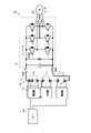
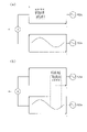
- FIG. 1 is a schematic configuration diagram of a power supply system
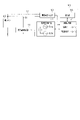
- FIG. 2 is a configuration diagram of a battery measuring device
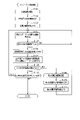
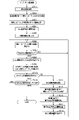
- FIG. 3 is a flowchart of impedance calculation processing
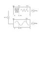
- FIG. 4 is a time chart showing transitions of AC signals that make up the composite wave
- FIG. 5 is a flowchart of the impedance calculation process of the second embodiment
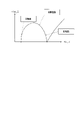
- FIG. 6 is a diagram showing an example of a cole-cole plot
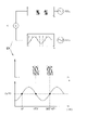
- FIG. 7 is a time chart showing AC signals forming a composite wave in a comparative example
- FIG. 8 is a time chart showing AC signals forming a composite wave in a comparative example of the third embodiment
- FIG. 9 is a configuration diagram of a battery measuring device in another example.
- a power supply system 10 includes a motor 20 as a rotating electrical machine, an inverter 30 as a power converter that supplies a three-phase current to the motor 20, a rechargeable battery 40, and a rechargeable battery 40. 40, and an ECU 60 for controlling the motor 20 and the like.
- the motor 20 is the vehicle's main engine, and can transmit power to drive wheels (not shown).
- a three-phase permanent magnet synchronous motor is used as the motor 20 .
- the inverter 30 is composed of a full bridge circuit having the same number of upper and lower arms as the number of phases of the phase windings, and by turning on and off the switches (semiconductor switching elements) provided in each arm, current flows in each phase winding. adjusted.
- the inverter 30 is provided with an inverter control device (not shown), and the inverter control device controls energization by turning on and off each switch in the inverter 30 based on various detection information in the motor 20 and requests for power running and power generation. to implement.
- the inverter control device supplies electric power from the assembled battery 40 to the motor 20 via the inverter 30 to drive the motor 20 in power running mode.
- the inverter control device causes the motor 20 to generate power based on the power from the drive wheels, converts the generated power via the inverter 30 and supplies it to the assembled battery 40 to charge the assembled battery 40 .
- the assembled battery 40 is electrically connected to the motor 20 via the inverter 30 .
- the assembled battery 40 has a terminal voltage of, for example, 100 V or more, and is configured by connecting a plurality of battery modules 41 in series.
- the battery module 41 is configured by connecting a plurality of battery cells 42 in series.
- As the battery cell 42 for example, a lithium ion storage battery or a nickel metal hydride storage battery can be used.
- Each battery cell 42 is a storage battery having an electrolyte and a plurality of electrodes.
- a positive terminal of an electrical load such as an inverter 30 is connected to a positive power supply path L1 connected to a positive power supply terminal of the assembled battery 40 .
- a negative terminal of an electrical load such as the inverter 30 is connected to the negative power supply path L2 connected to the negative power supply terminal of the assembled battery 40 .
- a relay switch SMR system main relay switch
- the battery measuring device 50 is a device that measures the state of charge (SOC) and the state of deterioration (SOH) of each battery cell 42 .
- the battery measuring device 50 is connected to the ECU 60, measures the state of each battery cell 42, and outputs the results.
- the configuration of the battery measuring device 50 will be described later.
- the ECU 60 requests the inverter control device for power running and power generation based on various information.
- the various information includes, for example, accelerator and brake operation information, vehicle speed, the state of the assembled battery 40, and the like.
- the battery measuring device 50 is provided so as to be able to measure the battery state of each battery cell 42 .
- the battery measuring device 50 includes an alternating current generating section 51 connected to each battery cell 42 via a first electrical path 81 and a voltage response measuring section 52 connected to each battery cell 42 via a second electrical path 82. , a modulation signal generator 53 connected to the alternating current generation unit 51, an arithmetic processing unit 54 connected to the voltage response measurement unit 52 and the modulation signal generator 53, and a communication unit 55 connected to the arithmetic processing unit 54. And prepare.
- the alternating current generator 51 outputs an alternating current using the battery cell 42 to be measured as a power source. Specifically, the alternating current generator 51 causes the battery cell 42 to output an alternating current based on the instruction signal input from the modulation signal generator 53 . When alternating current flows from the battery cell 42 , a response signal (voltage fluctuation) reflecting internal complex impedance information is generated in the voltage across the terminals of the battery cell 42 .
- the voltage response measuring unit 52 measures a response signal (voltage fluctuation) reflecting internal complex impedance information of the battery cell 42 between terminals of the battery cell 42 . Therefore, the voltage response measurement section 52 corresponds to a voltage measurement section.
- the modulation signal generator 53 includes a plurality of oscillators.
- the modulation signal generator 53 of this embodiment comprises two oscillators, a first oscillator 53a and a second oscillator 53b.
- the modulated signal generator 53 is configured to allow the oscillators 53a and 53b to generate AC signals in accordance with instructions from the arithmetic processing unit 54, and combine (superimpose) them to generate a composite wave.
- the AC signal generated by the first oscillator 53a may be referred to as the first AC signal
- the AC signal generated by the second oscillator 53b may be referred to as the second AC signal.
- the AC signal in this embodiment is a sine wave signal, it may be changed arbitrarily as long as it is an AC signal, and may be a rectangular wave, a triangular wave, or the like.
- a DC bias is applied to the composite wave or AC signal so that the AC current flowing from the battery cell 42 does not become a negative current (backflow to the battery cell 42).
- the modulated signal generator 53 converts the composite wave into a digital signal to generate an instruction signal, and instructs (outputs) the alternating current generator 51 to generate an alternating current based on the instruction signal. It should be noted that it is not always necessary to output the composite wave, and either the first AC signal or the second AC signal may be output as required.
- the arithmetic processing unit 54 has a microcomputer consisting of a CPU (arithmetic unit) and a storage device (various types of memory), and implements various control functions by executing programs stored in the storage device.
- Various functions may be implemented by an electronic circuit that is hardware, or may be implemented by both hardware and software.
- the arithmetic processing unit 54 has a function of calculating the complex impedance of the battery cell 42 .
- the arithmetic processing unit 54 instructs the modulation signal generator 53 about the measurement frequency of the complex impedance.
- the modulated signal generator 53 causes the battery cell 42 to generate an alternating current through the alternating current generation section 51 based on the instruction from the arithmetic processing section 54 .
- the voltage response measurement unit 52 measures the voltage between the terminals of the battery cell 42 , measures a response signal (voltage fluctuation) responding to the alternating current, and outputs the measured response signal to the arithmetic processing unit 54 .
- the arithmetic processing unit 54 calculates information about the complex impedance of the battery cell 42 based on the response signal. The arithmetic processing unit 54 repeats this series of processes until complex impedances are calculated for a plurality of predetermined measurement frequencies within the measurement range. Further, the arithmetic processing unit 54 notifies the ECU 60 of the calculation result.
- the ECU 60 creates, for example, a complex impedance plane plot (Cole-Cole plot) based on the calculation results, and grasps the characteristics of the electrodes, the electrolyte, and the like. For example, the state of charge (SOC) and the state of deterioration (SOH) are grasped.
- SOC state of charge
- SOH state of deterioration
- the complex impedance at a specific frequency is measured at regular time intervals, and changes in SOC, SOH, battery temperature, etc. during running may be grasped based on the time change of the complex impedance at the specific frequency.
- the complex impedance at a specific frequency may be measured at time intervals such as every day, every week, or every year, and changes in SOH and the like may be grasped based on time changes in the complex impedance at the specific frequency.
- the required accuracy in order to ensure the measurement accuracy of the complex impedance, it is necessary to average (integrate) the measured voltage fluctuation values to suppress the error. should be output and the voltage variation should be measured during that period.
- the required accuracy when the required accuracy is predetermined, it is necessary to output an AC signal with a wavenumber corresponding to the accuracy.
- the measurement frequency differs, the number of waves per unit time also differs. Therefore, if the measurement frequency is a low frequency, it will be necessary to output an alternating current for a longer period of time than when the measurement frequency is a high frequency. That is, the required output period differs for each measurement frequency.
- the battery measuring device 50 of the present embodiment is configured as follows. Details of the impedance calculation process will be described with reference to FIG.
- the arithmetic processing unit 54 executes the impedance calculation process shown in FIG. 3 at a predetermined timing.
- the predetermined timing is, for example, the time when the vehicle starts to start, the time when the vehicle stops, or a predetermined time within a day or a week. Moreover, it may be any timing while the vehicle is running.
- the complex impedance measurement frequency is set (step S101).
- the arithmetic processing unit 54 selects and sets a plurality of (two in this embodiment) measurement frequencies from among a plurality of predetermined frequencies within the measurement range.
- select (or slightly shift and adjust one frequency) so that any frequency is not an integral multiple of the other frequency. This is to avoid the influence of harmonic components. Note that it is not always necessary to set a plurality of (two in this embodiment) measurement frequencies, and if there is only one measurement frequency that can be set, that measurement frequency is set.
- the arithmetic processing unit 54 determines the output period of the AC signal based on the measurement frequency set in step S101 (step S102). When two measurement frequencies are set in step S101, the arithmetic processing unit 54 determines the output period for each of the first AC signal and the second AC signal. The output period is a period until the number of waves of the AC signal is output a predetermined number of times, and is calculated based on the measurement frequency. The predetermined number of times indicating the number of waves is determined in advance according to the required measurement accuracy.
- the arithmetic processing unit 54 indicates the set measurement frequency to the modulation signal generator 53 (step S103).
- the modulation signal generator 53 sets the frequency of the AC signal to be output to the oscillators 53a and 53b according to the instructed measurement frequency.
- the oscillators 53a and 53b of the modulation signal generator 53 then generate AC signals according to the set measurement frequency.
- the modulated signal generator 53 superimposes them to generate a composite wave.
- the modulated signal generator 53 converts the analog signal of the generated composite wave (or AC signal) into a digital signal, and outputs an instruction signal for outputting the composite wave (or AC signal) to the AC current generator 51 .
- the alternating current generator 51 causes the battery cell 42 to output an alternating current (composite wave, first alternating signal, or second alternating signal) based on the instruction signal.
- the voltage response measurement unit 52 measures the voltage between the terminals of the battery cell 42 , measures a response signal (voltage fluctuation) responding to the alternating current, and outputs the measured response signal to the arithmetic processing unit 54 .
- the arithmetic processing unit 54 calculates information about the complex impedance of the battery cell 42 based on the alternating current and voltage fluctuation (step S104). Specifically, the arithmetic processing unit 54 measures an alternating current and obtains measured values of a first alternating signal and a second alternating signal (or any of them) that constitute the alternating current. That is, the AC current flowing through the first electrical path 81 is measured, the measured AC current is analyzed by the frequency of each AC signal (measurement frequency), each AC signal (measurement signal) that actually flows is extracted, get. Note that the arithmetic processing unit 54 may receive and acquire each AC signal generated by the modulated signal generator 53 from the modulated signal generator 53 .
- the arithmetic processing unit 54 analyzes the response signal based on the acquired AC signal, and calculates a value proportional to the real part and a value proportional to the imaginary part of the response signal (information on complex impedance).
- the value proportional to the real part and the value proportional to the imaginary part of the response signal are average values (integrated values) from the start of output of each AC signal.
- the arithmetic processing unit 54 determines whether or not the output period of any of the AC signals (the first AC signal and the second AC signal) has ended (step S105). If the determination result is negative, the arithmetic processing unit 54 proceeds to step S104. That is, the arithmetic processing unit 54 continues measurement and calculation.
- step S105 determines whether the determination result in step S105 is affirmative.
- the arithmetic processing unit 54 stops generating the AC signal whose output period has ended (step S106).
- the modulated signal generator 53 stops generating the AC signal whose output period has ended. If there is an AC signal whose output period has not ended, the modulated signal generator 53 continues to generate the AC signal. After that, an instruction signal is generated based on the remaining AC signals and output to the AC current generator 51 until generation of a new AC signal is instructed.
- the arithmetic processing unit 54 acquires values proportional to the real part and the imaginary part of the response signal corresponding to the AC signal whose output period has ended, and based on these values, calculates All or one of the absolute value and phase of the complex impedance is calculated (step S107). Further, the arithmetic processing unit 54 notifies the calculated complex impedance to the ECU 60 .
- the arithmetic processing unit 54 determines whether or not all of the plurality of predetermined measurement frequencies within the measurement range have been selected (step S108). That is, it is determined whether or not the complex impedance has been calculated at each frequency in the measurement range.
- the arithmetic processing unit 54 selects and sets, as the measurement frequency, a frequency that has not yet been selected from among a plurality of predetermined frequencies within the measurement range (step S109). As in step S101, when selecting the measurement frequencies, select (or shift and adjust one of the frequencies) so that one of the frequencies is not an integral multiple of the other.
- the arithmetic processing unit 54 determines a new AC signal output period based on the newly set measurement frequency (step S110). The output period is determined in the same manner as in step S102.
- the arithmetic processing unit 54 instructs the newly set measurement frequency to the modulation signal generator 53 at a predetermined output timing (step S111).
- the predetermined output timing is, for example, the timing after a certain period of time has passed since the end of the output period of the previous AC signal.
- the modulated signal generator 53 causes the oscillators 53a and 53b for which the measurement frequency is not set among the oscillators 53a and 53b (that is, the oscillators 53a and 53b that do not output the AC signal) to newly output the AC signal according to the instructed measurement frequency. frequency is set. Then, the modulation signal generator 53 generates AC signals according to the two instructed measurement frequencies, and superimposes them to generate a composite wave. The modulated signal generator 53 converts the generated composite wave (analog signal) into a digital signal, and outputs an instruction signal for outputting the composite wave to the alternating current generator 51 .
- the alternating current generator 51 causes the battery cell 42 to output an alternating current (composite wave) based on the instruction signal.
- the voltage response measurement unit 52 measures the voltage between the terminals of the battery cell 42 , measures a response signal (voltage fluctuation) responding to the alternating current, and outputs the measured response signal to the arithmetic processing unit 54 .
- step S104 calculates information regarding the complex impedance of the battery cell 42 based on the alternating current and voltage fluctuation.
- step S108 determines whether or not the AC signal generated by the modulation signal generator 53 is present. That is, it is determined whether or not there is still an AC signal whose output period has not ended (step S112). If the determination result is affirmative, the arithmetic processing unit 54 proceeds to step S104 and calculates information regarding the complex impedance of the battery cell 42 for the remaining AC signals.
- step S112 determines whether the arithmetic processing unit 54 is capable of performing the following operations. If the determination result in step S112 is negative, that is, if the calculation of the complex impedance for all measurement frequencies is completed, the arithmetic processing unit 54 ends the impedance calculation process.
- the arithmetic processing unit 54 has a function as a current control unit 54a that causes the storage battery to output a composite wave obtained by superimposing a plurality of AC signals having different frequencies. Further, the calculation processing section 54 functions as a calculation section 54b that analyzes the voltage fluctuation for each frequency of the AC signal and calculates information on the complex impedance. Also, the impedance calculation method corresponds to the battery measurement method. Steps S101 to 103 and S109 to S111 correspond to current control steps. Step S104 corresponds to the voltage measurement step and the calculation step.
- each AC signal forming the composite wave is output as shown in FIG.
- the first AC signal is set to have a higher measurement frequency than the second AC signal.
- the first AC signal generated first is indicated as a first AC signal S11
- the first AC signal generated second is indicated as a first AC signal S12.
- the second AC signal is indicated as a second AC signal S21.
- the output period until the first AC signal S11 with the necessary wave number is output is shortened. Therefore, as shown in FIG. 4, when the composite wave of the first AC signal S11 and the second AC signal S21 is output as an AC current from time T0, the first AC signal S11 is generated earlier than the second AC signal S21. Output period ends. That is, the output period of the first AC signal S11 ends at time T1.
- the arithmetic processing unit 54 outputs a predetermined wave number for each AC signal that constitutes the composite wave.
- the arithmetic processing unit 54 continues to output the other AC signals, to an alternating signal with another frequency. For example, as shown in FIG. 4, the arithmetic processing unit 54 continues the output of the other second AC signal S21 when the output of the predetermined wave number of the first AC signal S11 forming the composite wave is completed. Meanwhile, the first AC signal S11 whose output has been completed is switched to the first AC signal S12 having another frequency.
- a new first AC signal S12 having a different measurement frequency can be obtained without waiting for the output period of the low-frequency second AC signal S21 to end. can be output as an alternating current. Therefore, compared to the case of setting a new composite wave after waiting for the end of the output period of the low-frequency first AC signal S11, efficiency can be improved.
- an AC signal having a predetermined wavenumber can be output to maintain the accuracy of complex impedance calculation.
- the arithmetic processing unit 54 sets the frequency of each of the AC signals forming the composite wave so that the frequency of any one of the AC signals forming the composite wave does not become an integral multiple of the frequency of the other AC signal. do. This prevents a certain frequency or its harmonic frequency from matching another frequency or its harmonic frequency, thereby suppressing an abnormal increase in the amplitude of the alternating current.
- the configuration of the first embodiment may be changed as in the following second embodiment.
- the second embodiment differences from the configurations described in the above embodiments will be mainly described.
- the power supply system 10 of the first embodiment will be described as an example of the basic configuration.
- the arithmetic processing unit 54 first sets the measurement frequency of the complex impedance in the same manner as in step S101 (step S201).
- the arithmetic processing unit 54 refers to the history of complex impedance stored in the storage device, etc., and estimates the magnitude of the complex impedance based on each measurement frequency set in step S201 (step S202). For example, it is assumed that the storage device stores a Cole-Cole plot as shown in FIG. 6 and a map showing the relationship between the measurement frequency and the measurement result when each measurement result was measured. In this case, the arithmetic processing unit 54 may refer to the map and calculate the estimated value of the magnitude (absolute value) of the complex impedance based on each measurement frequency set in step S201. Thereby, the arithmetic processing section 54 has a function as an estimating section for estimating the magnitude of the complex impedance.
- the arithmetic processing unit 54 sets the amplitude of the AC signal according to the magnitude of the estimated complex impedance for each measurement frequency (step S203). If the magnitude of the complex impedance is small, the amplitude of the AC signal is determined to be larger than the normal amplitude. This increases the voltage fluctuation in response to the AC signal and improves the measurement accuracy. For example, as shown in FIG. 6, when the measurement frequency is a band of about several kHz (high frequency) or a band of about several tens of Hz (low frequency), the estimated value of the magnitude of the complex impedance is small. Increase the amplitude of the signal. On the other hand, when the measurement frequency is in a band of about several hundred Hz (intermediate frequency), the amplitude of the AC signal is reduced (normal value) because the estimated value of the magnitude of the complex impedance is large.
- the arithmetic processing unit 54 adjusts the amplitude of the composite wave so that it falls within a predetermined range. Specifically, considering the DC bias superimposed on the composite wave, the maximum value of the composite wave (the value at which the instantaneous value is the maximum) is equal to or less than a predetermined maximum current value, and the minimum value of the composite wave The amplitude of each AC signal is determined so that (the value that minimizes the instantaneous value) is greater than or equal to a predetermined minimum current value.
- the maximum current value of the battery cell 42 is determined by, for example, the rated current.
- the arithmetic processing unit 54 determines the AC signal output period based on the measurement frequency set in step S201 (step S204). Next, the arithmetic processing unit 54 indicates the parameters (measurement frequency and amplitude) set in steps S202 and S203 to the modulation signal generator 53 (step S205). The modulation signal generator 53 sets the frequency and amplitude of the AC signal to be output to the oscillators 53a and 53b according to the designated parameters.
- the oscillators 53a and 53b of the modulation signal generator 53 generate AC signals according to the set measurement frequency and amplitude.
- the modulated signal generator 53 superimposes them to generate a composite wave.
- the modulated signal generator 53 converts the analog signal of the generated composite wave (or AC signal) into a digital signal, and outputs an instruction signal for outputting the composite wave (or AC signal) to the AC current generator 51 .
- the alternating current generator 51 causes the battery cell 42 to output an alternating current based on the instruction signal.
- the voltage response measurement unit 52 measures the voltage between the terminals of the battery cell 42 , measures the response signal responding to the alternating current, and outputs the measured response signal to the arithmetic processing unit 54 .
- steps S206 to S211 and S216 are the same as steps S104 to S109 and step S112, respectively, so detailed description thereof will be omitted.
- the arithmetic processing unit 54 After setting a new measurement frequency in step S211, the arithmetic processing unit 54 estimates the magnitude of the complex impedance based on the newly set measurement frequency in the same manner as in step S202 (step S212). Next, in the same manner as in step S203, the arithmetic processing unit 54 sets the amplitude of the AC signal for the new measurement frequency according to the magnitude of the estimated complex impedance (step S213).
- the arithmetic processing unit 54 determines a new AC signal output period based on the new measured frequency (step S214).
- the arithmetic processing unit 54 instructs the newly set measurement frequency and amplitude to the modulation signal generator 53 at a predetermined output timing (step S215).
- the predetermined output timing is, for example, the timing after a certain period of time has passed since the end of the output period of the previous AC signal.
- the frequency and amplitude of the AC signal to be newly output to the oscillators 53a and 53b for which the measurement frequency and amplitude are not set among the oscillators 53a and 53b are set according to the instructed measurement frequency and amplitude. be. Then, the modulated signal generator 53 generates AC signals according to the set measurement frequency and amplitude, and superimposes them to generate a composite wave. The modulated signal generator 53 outputs an instruction signal to the AC current generator 51 to output the generated composite wave.
- the alternating current generator 51 causes the battery cell 42 to output an alternating current (composite wave) based on the instruction signal.
- the voltage response measurement unit 52 measures the voltage between the terminals of the battery cell 42 , measures the response signal responding to the alternating current, and outputs the measured response signal to the arithmetic processing unit 54 .
- step S206 calculates information regarding the complex impedance of the battery cell 42 based on the alternating current and voltage fluctuation.
- the arithmetic processing unit 54 estimates the magnitude of the complex impedance for each frequency (measurement frequency) of the AC signal forming the composite wave. Then, when determining the amplitude of the AC signal forming the composite wave, the arithmetic processing unit 54 determines the amplitude of the AC signal according to the estimated value of the complex impedance according to the measurement frequency. Specifically, when the estimated value of the complex impedance is small, the amplitude of the AC signal is increased, and when the estimated value of the complex impedance is large, the amplitude of the AC signal is decreased. As a result, when the complex impedance is expected to be small, the amplitude of the AC signal can be increased to increase the voltage fluctuation corresponding to the AC signal. Therefore, the measurement accuracy is improved when the complex impedance is small.
- the arithmetic processing unit 54 adjusts the amplitude of the AC signal forming the composite wave so that the amplitude of the composite wave is within a predetermined range. Specifically, in consideration of the DC bias superimposed on the composite wave, the maximum value of the composite wave (the value at which the instantaneous value is maximum) is equal to or less than the predetermined maximum current value, and the minimum value of the composite wave The amplitude of each AC signal is determined so that (the value that minimizes the instantaneous value) is greater than or equal to a predetermined minimum current value.
- the configuration of the first embodiment may be changed as in the following third embodiment.
- the third embodiment differences from the configurations described in the above embodiments will be mainly described.
- the power supply system 10 of the second embodiment will be described as an example of the basic configuration.
- the measurement frequency of the complex impedance may be several kHz or more at high and several tens of Hz at low. . Therefore, when a low-frequency AC signal and a high-frequency AC signal are superimposed to form a composite wave, the output period of the high-frequency AC signal ends in a half cycle or less of the output of the low-frequency AC signal. Sometimes.
- the third embodiment is configured as follows.
- the output period of the high-frequency AC signal among the plurality of AC signals is one of the low-frequency AC signals. is less than or equal to half of the period of
- the arithmetic processing unit 54 determines whether or not the output period of the high-frequency AC signal of the first AC signal and the second AC signal is less than or equal to half the period of the low-frequency AC signal.
- the arithmetic processing unit 54 determines that the instantaneous value (displacement from the average value) of the low-frequency AC signal is closer to the average value than the maximum value or the minimum value, and the high-frequency AC signal The output start timing of the high-frequency AC signal is adjusted so that the output period of is set. More specifically, the arithmetic processing unit 54 adjusts the high-frequency AC signal so that the midpoint of the output period of the high-frequency AC signal coincides with the point at which the phase of the low-frequency AC signal becomes n ⁇ (n is a natural number). Sets the output period of the AC signal of the
- the arithmetic processing unit 54 operates at an intermediate point in the output period of the high-frequency AC signal and a point at which the displacement of the low-frequency AC signal becomes zero (a point at which the instantaneous value coincides with the average value). ), set the output period of the high-frequency AC signal.
- half of the output period of the high-frequency AC signal overlaps with the period in which the displacement of the low-frequency AC signal is more positive than the reference (average value, DC bias), and the remaining half is the period in which it is negative.
- the output period of the high-frequency AC signal overlaps with the period in which the displacement of the low-frequency AC signal is small.
- the arithmetic processing unit 54 sets the output period of the high-frequency AC signal in a period in which the instantaneous value (displacement from the average value) of the low-frequency AC signal is closer to the average value than the maximum value or the minimum value. Also, adjust the output start timing of the high-frequency AC signal. As a result, the bias of the AC current can be suppressed in comparison with the case where the output period of the high-frequency AC signal is set in the period where the instantaneous value of the low-frequency AC signal is close to the maximum value and the minimum value. can. Therefore, it is possible to suppress the state of the battery cell 42 from being changed by the output of the AC power.
- the arithmetic processing unit 54 performs a period in which the phase ⁇ of the low-frequency AC signal satisfies 0° ⁇ ⁇ ⁇ 45°, 135° ⁇ ⁇ ⁇ 225°, and 315° ⁇ ⁇ ⁇ 360°
- the output period of the high-frequency AC signal may be set inside. That is, in the case of a sinusoidal signal to which a DC bias is not applied, the output period of the high-frequency AC signal may be set during the period in which the instantaneous value (displacement) is less than half the amplitude.
- the method of analyzing the response signal (voltage fluctuation) for each measurement frequency, and measuring and calculating the amplitude, phase, etc. of the complex impedance may be any method.
- lock-in detection may be used. good too.
- heterodyne detection, Fourier transform, etc. may be used.
- lock-in amplifiers 101 and 102 may be provided for each of the AC signals forming the composite wave. Then, using a plurality of lock-in amplifiers 101 and 102, lock-in detection (two-phase lock-in detection) is performed on response signals simultaneously in a plurality of channels, the response signals are analyzed, and information on complex impedance (voltage fluctuation real part and imaginary part) may be obtained.
- the reference signal by which the response signal (voltage fluctuation) is multiplied may be an AC signal generated by the oscillators 53a and 53b, or may be an AC signal extracted from the feedback signal (detection signal). This makes it possible to calculate information about the complex impedance at a plurality of measurement frequencies at the same time.
- the battery measuring device 50 is provided with a stabilized power supply unit 103 .
- the stabilized power supply unit 103 is connected to the power supply line of the battery cell 42, and supplies power supplied from the battery cell 42 to various circuit elements (arithmetic processing unit 54, oscillators 53a and 53b, communication unit 55, etc.). We are supplying to.
- the measured response signal (voltage fluctuation) may be temporarily stored, and the stored response signal may be analyzed for each measurement frequency.
- the measured response signal voltage fluctuation
- lock-in detection two-phase detection
- the feedback signal detection signal
- the measured AC signal and the response signal voltage fluctuation
- the reference signal to be multiplied by the feedback signal may be the AC signal generated by the oscillators 53a and 53b.
- the arithmetic processing unit 54 does not need to calculate the absolute value and phase difference of the complex impedance, and calculates information about the complex impedance based on the response signal and the current signal, and outputs the information to an external device such as the ECU 60.
- the information about the complex impedance is, for example, intermediate progress (for example, only the real and imaginary parts of the current and voltage) necessary for calculating the absolute value of the complex impedance, the phase difference, and the like. Then, an external device may be caused to calculate the final result, that is, the absolute value of the complex impedance, the phase difference, and the like.
- the battery measuring device 50 of the above embodiment may be employed in HEVs, EVs, PHVs, auxiliary batteries, electric airplanes, electric motorcycles, and electric ships as vehicles. Moreover, in the above embodiment, the battery cells 42 may be connected in parallel.
- the AC signal is output from the battery cell 42, but an AC signal may be input to the battery cell 42 from an external power supply to provide disturbance. At this time, an AC signal may be input that equalizes the amount of charge and the amount of discharge so that the state of charge (SOC, etc.) of the battery cell 42 does not change due to the input of the AC signal. It should be noted that it is also possible to adjust the charge state of the battery cell 42 to a desired value by providing a difference between the amount of charged charge and the amount of discharged charge.
- the external power source may be one mounted on the vehicle or may be a device outside the vehicle.
- the battery measuring device 50 may measure the state of a storage battery other than the mounted battery 40 .
- the number of AC signals forming the composite wave may be arbitrarily changed.
- AC signals are generated by a plurality of oscillators 53a and 53b and synthesized, but an oscillator capable of generating an arbitrary waveform may be provided.
- the waveform of the composite wave itself may be stored, and an oscillator capable of generating the composite wave according to the waveform may be provided.
- the magnitude of the complex impedance is estimated for each frequency of the AC signal that constitutes the composite wave, the amplitude of the AC signal is determined according to the estimated value, and the complex impedance is determined based on the AC signal. was measured and calculated. At this time, if the calculated complex impedance value is less than or equal to a certain reference value compared to the estimated value before measurement, the amplitude of the AC signal may be increased and measurement may be performed again. This makes it possible to improve the measurement accuracy.
- the measured voltage fluctuations and AC currents may be stored, and analysis may be performed sequentially for each measurement frequency based on the stored voltage fluctuations and AC currents. In other words, it is not necessary to analyze voltage fluctuations for a plurality of AC signals at the same time.
- the wave number of the AC signal may be changed arbitrarily.
- the arithmetic processing unit 54 may set a larger number of waves to be input and output than when the electric load (inverter 30 or the like) connected to the battery cell 42 is activated or stopped.
- the disclosure in this specification is not limited to the illustrated embodiments.
- the disclosure encompasses the illustrated embodiments and variations thereon by those skilled in the art.
- the disclosure is not limited to the combinations of parts and/or elements shown in the embodiments.
- the disclosure can be implemented in various combinations.
- the disclosure can have additional parts that can be added to the embodiments.
- the disclosure encompasses omitting parts and/or elements of the embodiments.
- the disclosure encompasses permutations or combinations of parts and/or elements between one embodiment and another.
- the disclosed technical scope is not limited to the description of the embodiments.
- the disclosed technical scope is indicated by the description of the claims, and should be understood to include all modifications within the meaning and range of equivalents to the description of the claims.
- the controller and techniques described in this disclosure may be implemented by a dedicated computer provided by configuring a processor and memory programmed to perform one or more functions embodied by the computer program.
- the controls and techniques described in this disclosure may be implemented by a dedicated computer provided by configuring the processor with one or more dedicated hardware logic circuits.
- the control units and techniques described in this disclosure can be implemented by a combination of a processor and memory programmed to perform one or more functions and a processor configured by one or more hardware logic circuits. It may also be implemented by one or more dedicated computers configured.
- the computer program may also be stored as computer-executable instructions on a computer-readable non-transitional tangible recording medium.
Landscapes
- Physics & Mathematics (AREA)
- General Physics & Mathematics (AREA)
- Engineering & Computer Science (AREA)
- Power Engineering (AREA)
- Manufacturing & Machinery (AREA)
- Chemical & Material Sciences (AREA)
- Chemical Kinetics & Catalysis (AREA)
- Electrochemistry (AREA)
- General Chemical & Material Sciences (AREA)
- Measurement Of Resistance Or Impedance (AREA)
- Tests Of Electric Status Of Batteries (AREA)
- Charge And Discharge Circuits For Batteries Or The Like (AREA)
- Secondary Cells (AREA)
Priority Applications (3)
| Application Number | Priority Date | Filing Date | Title |
|---|---|---|---|
| DE112022003336.3T DE112022003336T5 (de) | 2021-06-30 | 2022-06-02 | Batteriemessverfahren und -gerät |
| CN202280046868.8A CN117597589A (zh) | 2021-06-30 | 2022-06-02 | 电池测定装置和电池测定方法 |
| US18/399,074 US20240230770A9 (en) | 2021-06-30 | 2023-12-28 | Battery measurement method and apparatus |
Applications Claiming Priority (2)
| Application Number | Priority Date | Filing Date | Title |
|---|---|---|---|
| JP2021-109557 | 2021-06-30 | ||
| JP2021109557A JP7559688B2 (ja) | 2021-06-30 | 2021-06-30 | 電池測定装置及び電池測定方法 |
Related Child Applications (1)
| Application Number | Title | Priority Date | Filing Date |
|---|---|---|---|
| US18/399,074 Continuation US20240230770A9 (en) | 2021-06-30 | 2023-12-28 | Battery measurement method and apparatus |
Publications (1)
| Publication Number | Publication Date |
|---|---|
| WO2023276546A1 true WO2023276546A1 (ja) | 2023-01-05 |
Family
ID=84691320
Family Applications (1)
| Application Number | Title | Priority Date | Filing Date |
|---|---|---|---|
| PCT/JP2022/022532 Ceased WO2023276546A1 (ja) | 2021-06-30 | 2022-06-02 | 電池測定装置及び電池測定方法 |
Country Status (5)
| Country | Link |
|---|---|
| US (1) | US20240230770A9 (enExample) |
| JP (1) | JP7559688B2 (enExample) |
| CN (1) | CN117597589A (enExample) |
| DE (1) | DE112022003336T5 (enExample) |
| WO (1) | WO2023276546A1 (enExample) |
Families Citing this family (2)
| Publication number | Priority date | Publication date | Assignee | Title |
|---|---|---|---|---|
| JP7775720B2 (ja) * | 2022-01-20 | 2025-11-26 | 株式会社デンソー | 二次電池システム |
| WO2025093896A1 (ja) * | 2023-11-03 | 2025-05-08 | 日産自動車株式会社 | インピーダンス計測装置及びインピーダンス計測方法 |
Citations (7)
| Publication number | Priority date | Publication date | Assignee | Title |
|---|---|---|---|---|
| JPS5547433A (en) * | 1978-10-02 | 1980-04-03 | Shiro Haruyama | Method of corrosion rate measurement and its device |
| JP2003090869A (ja) * | 2001-07-09 | 2003-03-28 | Yokogawa Electric Corp | インピーダンスの測定装置 |
| JP2012078339A (ja) * | 2010-09-10 | 2012-04-19 | Denso Corp | ガス濃度測定装置 |
| US20140176142A1 (en) * | 2012-12-20 | 2014-06-26 | Hyundai Autron Co., Ltd. | Method for diagnosing fault of fuel cell stack |
| KR101567248B1 (ko) * | 2014-10-21 | 2015-11-06 | 현대자동차주식회사 | 가변적 신호생성 및 신호수집 속도를 갖는 연료전지 임피던스 측정 방법 및 시스템 |
| JP2018190502A (ja) * | 2017-04-28 | 2018-11-29 | トヨタ自動車株式会社 | 二次電池システム |
| JP2021018069A (ja) * | 2019-07-17 | 2021-02-15 | 株式会社デンソー | 電池監視装置 |
Family Cites Families (3)
| Publication number | Priority date | Publication date | Assignee | Title |
|---|---|---|---|---|
| KR20140085802A (ko) * | 2012-12-27 | 2014-07-08 | 현대자동차주식회사 | 연료전지 스택의 상태 진단을 위한 임피던스 측정 방법 및 시스템 |
| JP7409097B2 (ja) | 2020-01-10 | 2024-01-09 | 住友ゴム工業株式会社 | タイヤ |
| JP2022007515A (ja) * | 2020-06-26 | 2022-01-13 | 株式会社デンソー | 電池診断システム |
-
2021
- 2021-06-30 JP JP2021109557A patent/JP7559688B2/ja active Active
-
2022
- 2022-06-02 CN CN202280046868.8A patent/CN117597589A/zh active Pending
- 2022-06-02 WO PCT/JP2022/022532 patent/WO2023276546A1/ja not_active Ceased
- 2022-06-02 DE DE112022003336.3T patent/DE112022003336T5/de active Pending
-
2023
- 2023-12-28 US US18/399,074 patent/US20240230770A9/en active Pending
Patent Citations (7)
| Publication number | Priority date | Publication date | Assignee | Title |
|---|---|---|---|---|
| JPS5547433A (en) * | 1978-10-02 | 1980-04-03 | Shiro Haruyama | Method of corrosion rate measurement and its device |
| JP2003090869A (ja) * | 2001-07-09 | 2003-03-28 | Yokogawa Electric Corp | インピーダンスの測定装置 |
| JP2012078339A (ja) * | 2010-09-10 | 2012-04-19 | Denso Corp | ガス濃度測定装置 |
| US20140176142A1 (en) * | 2012-12-20 | 2014-06-26 | Hyundai Autron Co., Ltd. | Method for diagnosing fault of fuel cell stack |
| KR101567248B1 (ko) * | 2014-10-21 | 2015-11-06 | 현대자동차주식회사 | 가변적 신호생성 및 신호수집 속도를 갖는 연료전지 임피던스 측정 방법 및 시스템 |
| JP2018190502A (ja) * | 2017-04-28 | 2018-11-29 | トヨタ自動車株式会社 | 二次電池システム |
| JP2021018069A (ja) * | 2019-07-17 | 2021-02-15 | 株式会社デンソー | 電池監視装置 |
Also Published As
| Publication number | Publication date |
|---|---|
| US20240133960A1 (en) | 2024-04-25 |
| JP2023006784A (ja) | 2023-01-18 |
| JP7559688B2 (ja) | 2024-10-02 |
| DE112022003336T5 (de) | 2024-04-11 |
| CN117597589A (zh) | 2024-02-23 |
| US20240230770A9 (en) | 2024-07-11 |
Similar Documents
| Publication | Publication Date | Title |
|---|---|---|
| US11644512B2 (en) | Battery monitoring device | |
| JP7259614B2 (ja) | 電池監視装置 | |
| US20230090001A1 (en) | Battery diagnostic system | |
| JP7552776B2 (ja) | 電池監視装置 | |
| CN102043127B (zh) | 用于执行电机转子的故障诊断的方法和系统 | |
| US20240133960A1 (en) | Battery measurement method and apparatus | |
| US20240230777A9 (en) | Battery measurement device | |
| WO2023189179A1 (ja) | 2次電池のインピーダンス測定装置 | |
| US9304173B2 (en) | Determining the internal resistance of a battery cell of a traction battery that is connected to a controllable motor/generator | |
| CN117597592A (zh) | 电池测定装置以及电池测定方法 | |
| JP2023105941A (ja) | 二次電池システム | |
| JP2013160613A (ja) | 蓄電池特性導出装置 | |
| Gadoue et al. | Electrochemical impedance spectroscopy state of charge measurement for batteries using power converter modulation | |
| CN114616478B (zh) | 电池监视装置 | |
| US20240168100A1 (en) | Battery measurement apparatus and battery state measurement method | |
| JP2021018946A (ja) | 電池監視装置 | |
| JP6759465B2 (ja) | ハイブリッド車両 | |
| Diao et al. | A nonlinear observer for DC bus voltage estimation and sensor diagnosis for a battery charger used in automotive systems | |
| JP2019102136A (ja) | 燃料電池システム | |
| JP2023154277A (ja) | パワーユニット | |
| Pan et al. | An Online Impedance Measurement Method of Energy Storage Battery Based on DC-DC | |
| JP2025057539A (ja) | 電流測定システム及び電流測定方法 | |
| JP2005341759A (ja) | ハイブリッド車のバッテリ管理装置 | |
| Gadoue et al. | 2 Department of Electrical and Electronic Engineering, Imperial College London, United Kingdom 3 Department of Earth Science and Engineering, Imperial College London, United Kingdom E-mail: s. gadoue@ aston. ac. uk |
Legal Events
| Date | Code | Title | Description |
|---|---|---|---|
| 121 | Ep: the epo has been informed by wipo that ep was designated in this application |
Ref document number: 22832704 Country of ref document: EP Kind code of ref document: A1 |
|
| WWE | Wipo information: entry into national phase |
Ref document number: 202280046868.8 Country of ref document: CN |
|
| WWE | Wipo information: entry into national phase |
Ref document number: 112022003336 Country of ref document: DE |
|
| 122 | Ep: pct application non-entry in european phase |
Ref document number: 22832704 Country of ref document: EP Kind code of ref document: A1 |