WO2023248387A1 - メンテナンス装置及びメンテナンスシステム - Google Patents
メンテナンス装置及びメンテナンスシステム Download PDFInfo
- Publication number
- WO2023248387A1 WO2023248387A1 PCT/JP2022/024938 JP2022024938W WO2023248387A1 WO 2023248387 A1 WO2023248387 A1 WO 2023248387A1 JP 2022024938 W JP2022024938 W JP 2022024938W WO 2023248387 A1 WO2023248387 A1 WO 2023248387A1
- Authority
- WO
- WIPO (PCT)
- Prior art keywords
- communication line
- communication
- unit
- air conditioning
- conditioning system
- Prior art date
- Legal status (The legal status is an assumption and is not a legal conclusion. Google has not performed a legal analysis and makes no representation as to the accuracy of the status listed.)
- Ceased
Links
Images





Classifications
-
- F—MECHANICAL ENGINEERING; LIGHTING; HEATING; WEAPONS; BLASTING
- F24—HEATING; RANGES; VENTILATING
- F24F—AIR-CONDITIONING; AIR-HUMIDIFICATION; VENTILATION; USE OF AIR CURRENTS FOR SCREENING
- F24F11/00—Control or safety arrangements
- F24F11/30—Control or safety arrangements for purposes related to the operation of the system, e.g. for safety or monitoring
- F24F11/49—Control or safety arrangements for purposes related to the operation of the system, e.g. for safety or monitoring ensuring correct operation, e.g. by trial operation or configuration checks
-
- F—MECHANICAL ENGINEERING; LIGHTING; HEATING; WEAPONS; BLASTING
- F24—HEATING; RANGES; VENTILATING
- F24F—AIR-CONDITIONING; AIR-HUMIDIFICATION; VENTILATION; USE OF AIR CURRENTS FOR SCREENING
- F24F2110/00—Control inputs relating to air properties
- F24F2110/50—Air quality properties
Definitions
- the present disclosure relates to a maintenance device and a maintenance system.
- Air conditioning systems for buildings are known that include a central control device, multiple outdoor units, and multiple indoor units connected by communication lines such as centralized transmission lines and internal/external transmission lines.
- a maintenance device which is a maintenance device, is temporarily connected to the communication line of the air conditioning system.
- These operations may be performed from the maintenance device.
- Patent Document 1 describes a data collection system in which a collection device is temporarily connected to an air conditioning system via a hypothetical cable, and the collection device performs data collection processing.
- Some air conditioning systems are known that supply power to each device via communication lines. When connecting a maintenance device to such a communication line, it is necessary to cut off power supply to each device before connecting. Therefore, there is a problem that the air conditioning system cannot be used during that time. It is also conceivable to connect the maintenance device to the air conditioning system by working with a live line while maintaining the power supply. However, in this case, special skills and qualifications are required of the workers, and protective measures are required to prevent electric shock. Furthermore, if the connection is made incorrectly, there is a risk that the equipment will malfunction.
- the present disclosure has been made in view of the above circumstances, and an object of the present disclosure is to provide a maintenance device and a maintenance system that can be easily connected to an air conditioning system for communication while maintaining power supply to the air conditioning system. With the goal.
- the maintenance device includes: A connection means for connecting in a contactless manner to a communication line of an air conditioning system in which at least some of the plurality of component devices are connected by a communication line that transmits and receives high-frequency signals; Communication means for communicating with the air conditioning system via the connection means using electromagnetic waves having the same frequency as the high frequency signal; Equipped with.
- a diagram showing the overall configuration of a maintenance system in an embodiment of the present disclosure Block diagram showing the configuration of a central management device in an embodiment of the present disclosure
- a block diagram showing the configuration of an outdoor unit in an embodiment of the present disclosure A block diagram showing the configuration of an indoor unit in an embodiment of the present disclosure
- Block diagram showing the configuration of a maintenance device in an embodiment of the present disclosure A diagram showing the relationship between cables used for communication lines, ease of occurrence of crosstalk, and recommended mounting positions of connection parts in an embodiment of the present disclosure.
- a diagram showing a functional configuration of a control unit of a maintenance device in an embodiment of the present disclosure Flowchart showing the procedure of maintenance processing in the embodiment of the present disclosure
- a block diagram showing the configuration of a maintenance device in Modification 1 of the present disclosure Diagram for explaining modification example 2 of the present disclosure A diagram showing the overall configuration of a maintenance system in Modification 4 of the present disclosure
- FIG. 1 is a diagram showing the overall configuration of a maintenance system 100 according to an embodiment of the present disclosure.
- the maintenance system 100 includes an air conditioning system 1 and a maintenance device 10 temporarily connected to the air conditioning system 1.
- the air conditioning system 1 is, for example, a multi-air conditioning system for buildings that air-conditions buildings such as office buildings and commercial facilities.
- the air conditioning system 1 includes a central control device 20, a plurality of outdoor units 30a to 30c, and a plurality of indoor units 40a to 40f as a plurality of component devices.
- the central control device 20 and each of the outdoor units 30a to 30c are connected in a daisy chain via a communication line 50A, which is a so-called centralized transmission line.
- the central management device 20 and each of the outdoor units 30a to 30c communicate with each other by transmitting and receiving a high frequency signal of a first frequency of 100 kHz or more via the communication line 50A.
- the communication line 50A is connected to a power source (not shown), and supplies power to the central management device 20 and the outdoor units 30a to 30c.
- the outdoor unit 30a and indoor units 40a and 40b, the outdoor unit 30b and indoor units 40c and 40d, and the outdoor unit 30c and indoor units 40e and 40f are connected by a communication line 50B, which is a so-called internal and external transmission line.
- the outdoor unit 30a and the indoor units 40a, 40b, the outdoor unit 30b and the indoor units 40c, 40d, and the outdoor unit 30c and the indoor units 40e, 40f each communicate at a frequency of 100 kHz or more different from the first frequency via the communication line 50B. Communication is performed by transmitting and receiving high frequency signals of a certain second frequency. Further, the communication line 50B is connected to a power source (not shown), and supplies power to the indoor units 40a to 40f.
- the outdoor units 30 without specifically specifying each one.
- the indoor units 40a to 40f will be referred to as indoor units 40 for common explanations without specifying each individual unit.
- the communication lines 50A and 50B are not distinguished, they are referred to as communication lines 50.
- the centralized management device 20 is a device for centrally managing the outdoor unit 30 and the indoor unit 40, and is installed, for example, in a management room in a building. As shown in FIG. 2, the centralized management device 20 includes a terminal block 21, a communication section 22, an input section 23, a display section 24, a storage section 25, and a control section 26.
- the terminal block 21 is an interface for connecting the central management device 20 to each outdoor unit 30.
- a connection port of the terminal block 21 is exposed to the outside of the casing of the central management device 20, and a communication line 50A is connected to the connection port. Note that the communication line 50A may be directly connected to the communication section 22 without providing the terminal block 21.
- the communication unit 22 communicates with each outdoor unit 30 connected via the terminal block 21 and the communication line 50A using a communication method using a high-frequency signal of the first frequency.
- the input unit 23 is, for example, an input device such as a keyboard, a mouse, a keypad, a push button, a touch panel, a touch pad, etc., and receives an input operation from a user and outputs a signal related to the received input operation to the control unit 26.
- the display unit 24 is, for example, a CRT display, a liquid crystal display, an organic EL display, a plasma display, etc., and displays screens and status for operating the outdoor unit 30 and the indoor unit 40 under the control of the control unit 26. Display screens etc.
- the storage unit 25 is composed of an EEPROM (Electrically Erasable Programmable Read-Only Memory), a readable/writable nonvolatile semiconductor memory such as a flash memory, an HDD (Hard Disk Drive), and the like.
- the storage unit 25 stores management programs, data, etc. for managing the outdoor unit 30.
- the control unit 26 is configured to include a CPU (Central Processing Unit), a ROM (Read Only Memory), a RAM (Random Access Memory), etc., and performs overall control of the central management device 20.
- a CPU Central Processing Unit
- ROM Read Only Memory
- RAM Random Access Memory
- the outdoor unit 30 includes a terminal block 31, a first communication section 32, a second communication section 33, a main unit 34, and a control section 35.
- the terminal block 31 is an interface for connecting the outdoor unit 30 to the central management device 20 and the indoor unit 40.
- a connection port of the terminal block 31 is exposed to the outside of the casing of the outdoor unit 30, and a communication line 50A and a communication line 50B are connected to the connection port.
- the communication line 50A may be directly connected to the first communication section 32 and the communication line 50B may be directly connected to the second communication section 33 without providing the terminal block 31.
- the first communication unit 32 communicates with the central management device 20 connected via the terminal block 31 and the communication line 50A under the control of the control unit 35 using a communication method using a high-frequency signal of a first frequency. conduct.
- the second communication unit 33 communicates with each indoor unit 40 connected via the terminal block 31 and the communication line 50B using a communication method using a high-frequency signal of a second frequency. conduct.
- the main unit 34 is a component for realizing the original functions of the general outdoor unit 30, and includes a refrigerant circuit including a compressor, a heat exchanger, an expansion valve, a four-way valve, etc., a fan, and various other components. Equipped with sensors (current sensor, temperature sensor, pressure sensor, frequency sensor, acceleration sensor, etc.).
- the control unit 35 is configured to include a CPU, ROM, RAM, etc. (all not shown), and centrally controls the outdoor unit 30.
- the indoor unit 40 includes a terminal block 41, a communication section 42, a main unit 43, and a control section 44.
- the terminal block 41 is an interface for connecting the indoor unit 40 to the outdoor unit 30.
- a connection port of the terminal block 41 is exposed to the outside of the casing of the indoor unit 40, and a communication line 50B is connected to the connection port. Note that the communication line 50B may be directly connected to the communication section 42 without providing the terminal block 41.
- the communication unit 42 communicates with the outdoor unit 30 connected via the terminal block 41 and the communication line 50B under the control of the control unit 44 using a communication method using a high-frequency signal of the second frequency.
- the main unit 43 is a component for realizing the original functions of a general indoor unit 40, and includes, for example, a fan, a heat exchanger, a temperature sensor, a humidity sensor, and the like.
- the measurement results of each sensor included in the main unit 43 are periodically transmitted to the outdoor unit 30 connected via a communication line 50B.
- the control unit 44 includes a CPU, ROM, RAM, etc. (all not shown), and controls the indoor unit 40 in an integrated manner.
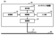
- the maintenance device 10 is a device that temporarily connects to the communication line 50 of the air conditioning system 1 to perform maintenance work, inspection work, work to identify the cause of a failure, etc. of the air conditioning system 1. It is. Although the maintenance device 10 is connected to the communication line 50B in FIG. 1, it can also be connected to the communication line 50A. As shown in FIG. 5, the maintenance device 10 includes a connection section 11, a communication section 12, an input section 13, a display section 14, a storage section 15, and a control section 16.
- the connection unit 11 is configured to electromagnetically connect to the communication line 50 of the air conditioning system 1 in a non-contact manner.
- the connecting portion 11 includes a cable portion whose one end is connected to the communication portion 12, and a clamp portion made of a highly conductive material provided at the other end of the cable.
- the connecting portion 11 connects to the communication line 50 in a non-contact manner by sandwiching and surrounding the communication line 50 with the clamp portion, that is, by clamping the communication line 50 .
- communication is performed between the components of the air conditioning system 1 using a communication method using high frequency signals, and the high frequency signals flow through the communication line 50.
- the communication unit 12 can receive the high frequency signal flowing through the communication line 50 via the connection unit 11. Further, the communication unit 12 can transmit a signal, which is an electromagnetic wave having the same frequency as the high-frequency signal flowing through the communication line 50, from the communication line 50 clamped at the connection unit 11 to the destination device.
- the connecting portion 11 is an example of a connecting means of the present disclosure.
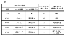
- Figure 6 shows the characteristics of the cable used for the communication line 50, information indicating the ease with which crosstalk occurs in the cable in three stages of " ⁇ ", " ⁇ ", and " ⁇ " in order of ease of occurrence, and recommended information.
- 12 is a table summarizing the relationship between the mounting position of the connecting portion 11 and the mounting position of the connecting portion 11.
- the connecting portion 11 can be attached to any position on the communication line 50.
- connection part 11 to the part of the communication line 50 in the vicinity of the connection port of the terminal blocks 21, 31, 41 where the sheet is removed.
- the communication unit 12 communicates between the connection unit 11 and the communication line 50 using a communication method using electromagnetic waves having the same frequency as the high frequency signal used for communication in the air conditioning system 1. It communicates with each component of the air conditioning system 1 connected via. For example, when the connection unit 11 is connected to the communication line 50A, the communication unit 12 communicates with each component of the air conditioning system 1 using a communication method using a high frequency signal of the first frequency. Moreover, when the connection part 11 is connected to the communication line 50B, the communication part 12 communicates with each component of the air conditioning system 1 by a communication method using a high frequency signal of the second frequency.
- the communication unit 12 is an example of communication means of the present disclosure.
- the input unit 13 is, for example, an input device such as a keyboard, a mouse, a keypad, a push button, a touch panel, a touch pad, etc., and receives an input operation from a user and sends a signal related to the accepted input operation to the control unit 16.
- the display unit 14 is, for example, a liquid crystal display, an organic EL display, or the like, and displays screens for operating the outdoor unit 30 and indoor unit 40, screens for displaying operating status, etc. under the control of the control unit 16. indicate.
- the storage unit 15 is composed of an EEPROM (Electrically Erasable Programmable Read-Only Memory), a readable/writable nonvolatile semiconductor memory such as a flash memory, an HDD (Hard Disk Drive), and the like.
- the storage unit 15 stores management programs, data, etc. for maintaining and inspecting the outdoor unit 30 and the indoor unit 40.
- the control unit 16 is configured to include a CPU, ROM, RAM, etc. (all not shown), and performs overall control of the maintenance device 10. As shown in FIG. 7, the control unit 16 includes a communication determination unit 161, a connection position change notification unit 162, a frequency identification unit 163, and a maintenance processing unit 164 as functional configurations.
- the communication determination unit 161 determines whether the communication unit 12 can communicate well with the air conditioning system 1.
- the connection position change notification unit 162 executes a process for prompting the user to change the connection position of the connection unit 11 to the communication line 50 when the communication determination unit 161 determines that good communication with the air conditioning system 1 is not possible. do.
- the communication determination unit 161 is an example of communication determination means of the present disclosure.
- the connection position change notification unit 162 is an example of connection position change notification means of the present disclosure. The details of the processing executed by the communication determination section 161 and the connection position change notification section 162 will be described later.
- the frequency identification unit 163 identifies the frequency of the high frequency signal flowing through the communication line 50 to which the connection unit 11 is connected in a non-contact manner. That is, when the connecting section 11 is connected to the communication line 50A, the frequency specifying section 163 specifies the first frequency, and when the connecting section 11 is connected to the communication line 50B, the frequency specifying section 163 specifies the second frequency. Identify.
- the frequency specifying unit 163 is an example of a frequency specifying means of the present disclosure.
- the maintenance processing unit 164 executes various processes necessary for maintenance work, inspection work, etc. For example, the maintenance processing unit 164 executes a process of acquiring and analyzing operating data from the indoor unit 40 via the connection unit 11 and the communication unit 12, a process of transmitting a control command, and the like.
- a user who is an administrator, worker, etc. of the air conditioning system 1 clamps the communication line 50 of the air conditioning system 1 with the clamp part of the connection part 11 of the maintenance device 10 in order to perform maintenance work, inspection work, etc. of the air conditioning system 1. do. At this time, there is no need to stop the power supply to the air conditioning system 1.
- the user then operates the input unit 13 of the maintenance device 10 to instruct the start of maintenance work.
- the control unit 16 of the maintenance device 10 executes the maintenance process shown in FIG. 8. Note that the control unit 16 may automatically start the maintenance process when the connection unit 11 is clamped to the communication line 50 without waiting for an operation from the user.
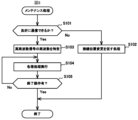
- the communication determination unit 161 of the maintenance device 10 first determines whether the communication unit 12 can communicate well with the air conditioning system 1 connected via the connection unit 11 (step S101). Specifically, the communication determination unit 161 causes the communication unit 12 to transmit a response request signal to the outdoor unit 30. Then, the communication determining unit 161 makes the above determination based on the time from when the communication unit 12 transmits the response request signal to when the outdoor unit 30 receives the response signal. Note that the above-described determination method is an example, and the communication determination unit 161 may determine whether or not the communication unit 12 can communicate well with the air conditioning system 1 using other methods.
- connection position change notification unit 162 performs a process for prompting the user to change the connection position of the connection unit 11 (step S102).
- connection position change notification section 162 causes the display section 14 to display a message saying "Please clamp the communication line near the terminal block."
- the connection position change notification unit 162 may output a similar message by voice, or if the maintenance device 10 has an Internet connection function, a similar message may be output on the user's smartphone. The message may be sent by email, SMS, etc. The maintenance process then ends.
- the frequency identification unit 163 detects the high frequency that is flowing through the communication line 50 to which the connection unit 11 is connected in a non-contact manner.
- the frequency of the signal is specified (step S103).
- the frequency specifying unit 163 may analyze the response signal received from the outdoor unit 30 and specify the frequency in order to make the determination in step S101. If the connection unit 11 is connected to the communication line 50A, the first frequency is specified in step S103. If the connection unit 11 is connected to the communication line 50B, the second frequency is specified in step S103.
- Step S103 the user operates the input unit 13 of the maintenance device 10 to perform various operations for performing maintenance work, and the maintenance processing unit 164 executes various processes in accordance with the operations ( Step S104). Furthermore, at this time, the maintenance processing unit 164 controls the communication unit 12 as necessary to communicate with each component of the air conditioning system 1 connected via the connection unit 11 and the communication line 50.
- the maintenance processing unit 164 instructs the communication unit 12 to transmit data such as control commands and information acquisition request commands as necessary.
- the communication section 12 Upon receiving the instruction, the communication section 12 generates an electromagnetic wave having the same frequency as the frequency specified in step S103, on which the instructed data is superimposed, and causes the electromagnetic wave to be output from the connection section 11. Thereby, data can be transmitted to the target device via the communication line 50 that is connected to the connection unit 11 in a non-contact manner.
- the maintenance processing unit 164 acquires data such as operating data of the indoor unit 40 and environmental information from the high frequency signal received by the communication unit 12 via the connection unit 11, as necessary.
- step S105 the user performs an operation to end the maintenance process from the input unit 13 (step S105; Yes), and the maintenance process ends.
- the maintenance device 10 by utilizing crosstalk, power can be supplied to the air conditioning system 1 by simply clamping the communication line 50 through which a high-frequency signal is flowing at the connection part 11. It becomes possible to easily connect to this air conditioning system 1 in a communicable manner while maintaining the same.
- the maintenance device 10 when the connection state with the air conditioning system 1 is not good, a process for prompting the user to change the connection position of the connection part 11 is executed. Therefore, the effect of improving communication problems with the air conditioning system 1 can be expected.
- connection unit 11 was electromagnetically connected to the communication line 50 in a non-contact manner by clamping the communication line 50.
- the connecting portion 11 may be electromagnetically connected to the communication line 50 in a non-contact manner by other methods.
- crosstalk with the communication line 50 will occur even if the connection part 11 is made up of only a cable part and at least a part of the connection part 11 is placed along the communication line.
- the connecting portion 11 can be electromagnetically connected to the communication line 50 without contact. In this case, it is desirable that the cable portion of the connecting portion 11 be a CVV cable, which is likely to cause crosstalk.
- the communication lines 50A and 50B of the air conditioning system 1 communicate using high frequency signals of different frequencies, but the communication lines 50A and 50B both communicate using high frequency signals of the same frequency. You can. In this case, no matter which communication line 50A or 50B the connection unit 11 is connected to, the frequency of the received high-frequency signal is the same, so the process of identifying the frequency in step S103 of the maintenance process can be omitted. . Furthermore, communication using high-frequency signals may be performed using only one of the communication lines 50A and 50B of the air conditioning system 1. In this case, the connection unit 11 needs to be connected to the communication lines 50A and 50B that communicate using high-frequency signals.
- the portion of the communication line 50 within a predetermined range from the connection port of the terminal blocks 21, 31, 41 can be distinguished from other portions. May be displayed. For example, in FIG. 10, a marker M1 is attached to the communication line 50 within 10 cm from the connection port of the terminal blocks 21, 31, 41. The connecting portion 11 of the maintenance device 10 is clamped to the communication line 50 of this marker portion. By doing so, the user can connect the connection unit 11 to an appropriate position of the communication line 50 where crosstalk is likely to occur.
- a terminal block 70 is connected to the terminal block 41 of the indoor unit 40b, which is a component of the air conditioning system 1, via a coupling circuit 60.
- the maintenance device 10 may be communicably connected to the connection port of the terminal block 70 via a general cable 80. This makes it possible to easily connect the maintenance device 10 to the air conditioning system 1 in a communicable manner while maintaining power supply to the air conditioning system 1. Note that in this case, the maintenance device 10 does not need to be provided with the connection portion 11. Further, the terminal block 70 for connecting the maintenance device 10 may be similarly connected to the terminal blocks 21, 31, and 41 of component devices other than the indoor unit 40b.
- the air conditioning system 1 including one central control device 20, three outdoor units 30a to 30c, and six indoor units 40a to 40f is used as an example.
- the number of these devices constituting the air conditioning system 1 is arbitrary.
- the air conditioning system 1 may include devices other than the central control device 20, the outdoor unit 30, and the indoor unit 40.
Landscapes
- Engineering & Computer Science (AREA)
- Chemical & Material Sciences (AREA)
- Combustion & Propulsion (AREA)
- Mechanical Engineering (AREA)
- General Engineering & Computer Science (AREA)
- Air Conditioning Control Device (AREA)
Priority Applications (2)
| Application Number | Priority Date | Filing Date | Title |
|---|---|---|---|
| PCT/JP2022/024938 WO2023248387A1 (ja) | 2022-06-22 | 2022-06-22 | メンテナンス装置及びメンテナンスシステム |
| JP2024528176A JP7734842B2 (ja) | 2022-06-22 | 2022-06-22 | メンテナンス装置及びメンテナンスシステム |
Applications Claiming Priority (1)
| Application Number | Priority Date | Filing Date | Title |
|---|---|---|---|
| PCT/JP2022/024938 WO2023248387A1 (ja) | 2022-06-22 | 2022-06-22 | メンテナンス装置及びメンテナンスシステム |
Publications (1)
| Publication Number | Publication Date |
|---|---|
| WO2023248387A1 true WO2023248387A1 (ja) | 2023-12-28 |
Family
ID=89379255
Family Applications (1)
| Application Number | Title | Priority Date | Filing Date |
|---|---|---|---|
| PCT/JP2022/024938 Ceased WO2023248387A1 (ja) | 2022-06-22 | 2022-06-22 | メンテナンス装置及びメンテナンスシステム |
Country Status (2)
| Country | Link |
|---|---|
| JP (1) | JP7734842B2 (https=) |
| WO (1) | WO2023248387A1 (https=) |
Citations (5)
| Publication number | Priority date | Publication date | Assignee | Title |
|---|---|---|---|---|
| JP2002031394A (ja) * | 2000-07-14 | 2002-01-31 | Sanyo Electric Co Ltd | 制御装置及びこの制御装置を用いた空気調和装置 |
| JP2009273203A (ja) * | 2008-05-01 | 2009-11-19 | Nishimu Electronics Industries Co Ltd | 有線式配電線遠方監視制御用通信ケーブルの障害点またはルートの探査方法および探査装置 |
| CN102890205A (zh) * | 2011-07-20 | 2013-01-23 | 珠海格力电器股份有限公司 | 变频空调数据采集分析仪 |
| WO2018100655A1 (ja) * | 2016-11-30 | 2018-06-07 | 株式会社日立製作所 | データ収集システム、異常検出方法、及びゲートウェイ装置 |
| JP2020167576A (ja) * | 2019-03-29 | 2020-10-08 | ダイキン工業株式会社 | 機器ネットワークシステム |
Family Cites Families (2)
| Publication number | Priority date | Publication date | Assignee | Title |
|---|---|---|---|---|
| US4132355A (en) * | 1977-05-18 | 1979-01-02 | Energy Master, Inc. | Electronic temperature control system |
| JP2005172757A (ja) * | 2003-12-15 | 2005-06-30 | Alps Electric Co Ltd | 液面レベルセンサ |
-
2022
- 2022-06-22 WO PCT/JP2022/024938 patent/WO2023248387A1/ja not_active Ceased
- 2022-06-22 JP JP2024528176A patent/JP7734842B2/ja active Active
Patent Citations (5)
| Publication number | Priority date | Publication date | Assignee | Title |
|---|---|---|---|---|
| JP2002031394A (ja) * | 2000-07-14 | 2002-01-31 | Sanyo Electric Co Ltd | 制御装置及びこの制御装置を用いた空気調和装置 |
| JP2009273203A (ja) * | 2008-05-01 | 2009-11-19 | Nishimu Electronics Industries Co Ltd | 有線式配電線遠方監視制御用通信ケーブルの障害点またはルートの探査方法および探査装置 |
| CN102890205A (zh) * | 2011-07-20 | 2013-01-23 | 珠海格力电器股份有限公司 | 变频空调数据采集分析仪 |
| WO2018100655A1 (ja) * | 2016-11-30 | 2018-06-07 | 株式会社日立製作所 | データ収集システム、異常検出方法、及びゲートウェイ装置 |
| JP2020167576A (ja) * | 2019-03-29 | 2020-10-08 | ダイキン工業株式会社 | 機器ネットワークシステム |
Also Published As
| Publication number | Publication date |
|---|---|
| JP7734842B2 (ja) | 2025-09-05 |
| JPWO2023248387A1 (https=) | 2023-12-28 |
Similar Documents
| Publication | Publication Date | Title |
|---|---|---|
| CN100495462C (zh) | 用于测试空调的设备 | |
| US20150176854A1 (en) | HVAC Communication Bus Decoders and Corresponding Methods | |
| CN109937331B (zh) | 空调机以及空调系统 | |
| CN103984338B (zh) | 空调控制器自动测试系统及其测试方法 | |
| CN107741078B (zh) | 检测装置和检测方法 | |
| CN101169658B (zh) | 用于检测多类型空调中的通信异常的装置和方法 | |
| EP4187372A1 (en) | Method and apparatus for maintaining software of a control unit for an industrial control system | |
| CN104764159A (zh) | 一种多联机定位室内机的方法及多联机 | |
| WO2023248387A1 (ja) | メンテナンス装置及びメンテナンスシステム | |
| WO2024005203A1 (ja) | サーバ装置、空気調和装置の管理方法、および空調システム | |
| JP4325593B2 (ja) | 空調機対応付け支援システム | |
| US11913661B2 (en) | Air-conditioning system | |
| EP1662210A1 (en) | Apparatus for monitoring air conditioner | |
| JP2006207946A (ja) | 異常検出装置 | |
| KR102729083B1 (ko) | 공기 조화기 및 공기 조화기 점검방법 | |
| JP3858827B2 (ja) | 情報管理システム | |
| JP6964797B2 (ja) | 空調システム及び空調管理システム | |
| JP2023157070A (ja) | 空調システムおよび空調システムの制御方法 | |
| CN210345781U (zh) | 空调内机诊断系统 | |
| EP4270180A1 (en) | Update device, indoor and outdoor units, update system, update method and programme | |
| CN100437510C (zh) | 供暖、通风和空调系统中全系统故障的有序记录 | |
| JP4592718B2 (ja) | ネットワーク識別id設定方法、通信ネットワークシステム | |
| JP2002333196A (ja) | 設備機器監視システム | |
| CN210320503U (zh) | 一种用于空调研发的智能试验监控装置 | |
| WO2023135785A1 (ja) | 冷媒漏洩監視システムおよび冷媒漏洩監視方法 |
Legal Events
| Date | Code | Title | Description |
|---|---|---|---|
| 121 | Ep: the epo has been informed by wipo that ep was designated in this application |
Ref document number: 22947948 Country of ref document: EP Kind code of ref document: A1 |
|
| ENP | Entry into the national phase |
Ref document number: 2024528176 Country of ref document: JP Kind code of ref document: A |
|
| NENP | Non-entry into the national phase |
Ref country code: DE |
|
| 122 | Ep: pct application non-entry in european phase |
Ref document number: 22947948 Country of ref document: EP Kind code of ref document: A1 |