WO2023248358A1 - 空気清浄機、空気調和機および換気扇 - Google Patents
空気清浄機、空気調和機および換気扇 Download PDFInfo
- Publication number
- WO2023248358A1 WO2023248358A1 PCT/JP2022/024758 JP2022024758W WO2023248358A1 WO 2023248358 A1 WO2023248358 A1 WO 2023248358A1 JP 2022024758 W JP2022024758 W JP 2022024758W WO 2023248358 A1 WO2023248358 A1 WO 2023248358A1
- Authority
- WO
- WIPO (PCT)
- Prior art keywords
- air
- conductive
- air cleaner
- casing
- housing
- Prior art date
- Legal status (The legal status is an assumption and is not a legal conclusion. Google has not performed a legal analysis and makes no representation as to the accuracy of the status listed.)
- Ceased
Links
Images






Classifications
-
- F—MECHANICAL ENGINEERING; LIGHTING; HEATING; WEAPONS; BLASTING
- F24—HEATING; RANGES; VENTILATING
- F24F—AIR-CONDITIONING; AIR-HUMIDIFICATION; VENTILATION; USE OF AIR CURRENTS FOR SCREENING
- F24F8/00—Treatment, e.g. purification, of air supplied to human living or working spaces otherwise than by heating, cooling, humidifying or drying
- F24F8/10—Treatment, e.g. purification, of air supplied to human living or working spaces otherwise than by heating, cooling, humidifying or drying by separation, e.g. by filtering
- F24F8/192—Treatment, e.g. purification, of air supplied to human living or working spaces otherwise than by heating, cooling, humidifying or drying by separation, e.g. by filtering by electrical means, e.g. by applying electrostatic fields or high voltages
-
- F—MECHANICAL ENGINEERING; LIGHTING; HEATING; WEAPONS; BLASTING
- F24—HEATING; RANGES; VENTILATING
- F24F—AIR-CONDITIONING; AIR-HUMIDIFICATION; VENTILATION; USE OF AIR CURRENTS FOR SCREENING
- F24F8/00—Treatment, e.g. purification, of air supplied to human living or working spaces otherwise than by heating, cooling, humidifying or drying
- F24F8/80—Self-contained air purifiers
Definitions
- the present disclosure relates to an air purifier for purifying indoor air, an air conditioner having an indoor air purifying function, and a ventilation fan.
- Patent Document 1 discloses an indoor unit of an air conditioner equipped with a function to remove and purify impurities such as dust contained in indoor air.
- a conductor is provided around the ion generator, and by preventing the ion generator or the casing from being charged due to discharge by the conductor, the wall surface on which the indoor unit is installed is By preventing static electricity, the wall surface is prevented from becoming dirty due to dust adhering to the wall surface.
- the present disclosure has been made in view of the above, and can prevent soiling of the installation surface caused by the electric field extending from the air purifier to the installation surface on which the air purifier is installed, without requiring grounding work.
- the purpose is to obtain an air purifier.
- an air cleaner is an air cleaner that is installed on an indoor installation surface and purifies the indoor air.
- the air purifier has a rectangular parallelepiped-shaped housing having a first surface provided with an inlet for sucking air, and a second surface different from the first surface and provided with an outlet for blowing out air.
- a blower that is housed in a housing and generates an air flow that sucks in air from an inlet and blows out air from an outlet; and a discharge type electrostatic precipitator that is housed in a housing and removes impurities from the air flow. Equipped with.
- the casing has a conductive part having conductivity.
- the air purifier according to the present disclosure it is possible to prevent dirt on the installation surface caused by an electric field extending from the air purifier to the installation surface on which the air purifier is installed, without requiring grounding work. play.
- FIG. 1 is a diagram showing the appearance of the air cleaner according to Embodiment 1, and is a perspective view of the air cleaner seen from below.
- 1 is a diagram showing the appearance of the air cleaner according to Embodiment 1, and is a perspective view of the air cleaner seen from above.
- 2 is a configuration diagram schematically showing the configuration of the air cleaner according to Embodiment 1, and corresponds to a cross section taken along line III-III in FIG. 1.
- FIG. 2 is a diagram showing the appearance of an air cleaner according to a second embodiment, and is a perspective view of the air cleaner seen from below.
- FIG. 2 is a diagram showing the appearance of the air cleaner according to Embodiment 2, and is a perspective view of the air cleaner seen from above.
- 6 is a configuration diagram schematically showing the configuration of an air cleaner according to Embodiment 2, and corresponds to a cross section taken along line VII-VII in FIG. 5.
- FIG. A rear view of the air purifier casing according to Embodiment 2, showing an example of the appearance when conductive parts are arranged on four sides of the casing.
- An enlarged sectional view showing an enlarged view of the second side surface and the periphery of the conductive component in the air purifier housing according to the second embodiment.
- An enlarged sectional view showing a modification of other conductive parts of the air cleaner according to Embodiment 2 An enlarged cross-sectional view showing an enlarged view of the second side surface and the periphery of other conductive parts in the casing of the modified example of the air purifier according to the second embodiment.
- a configuration diagram showing an outline of the configuration of an air purifier according to Embodiment 3 An enlarged sectional view showing an enlarged periphery of a conductive component of an air cleaner according to a third embodiment
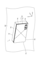
- FIG. 1 is a diagram showing the appearance of the air cleaner 1 according to the first embodiment, and is a perspective view of the air cleaner 1 viewed from below.
- FIG. 2 is a diagram showing the appearance of the air cleaner 1 according to the first embodiment, and is a perspective view of the air cleaner 1 viewed from above.
- FIG. 3 is a configuration diagram showing an outline of the configuration of the air cleaner 1 according to the first embodiment, and is a diagram corresponding to a cross section taken along the line III-III in FIG. 1. Note that in FIG. 3, some hatching is omitted for ease of understanding.
- the air cleaner 1 can be installed on a wall surface 500 and a ceiling surface, and is an air cleaner that removes contamination from indoor air and purifies the indoor air environment.
- the wall surface 500 and the ceiling surface are installation surfaces on which the air cleaner 1 is installed.
- the air cleaner 1 has a housing 10 that forms the outer shell of the air cleaner 1.
- the housing 10 includes a housing body 11 and a front panel 12, and has a rectangular parallelepiped shape.
- the housing 10 is made of conductive resin and has a rectangular parallelepiped shape in which the depth dimension is smaller than the width direction dimensions and the height direction dimensions.
- the width direction of the air cleaner 1 corresponds to the width direction of the housing 10, and corresponds to the X-axis direction in FIGS. 1 to 3.
- the width direction of the air cleaner 1 can be referred to as the left-right direction.
- the depth direction of the air cleaner 1 corresponds to the depth direction of the housing 10, and corresponds to the Y-axis direction in FIGS. 1 to 3.
- the depth direction of the air cleaner 1 can be referred to as the thickness direction of the air cleaner 1 or the thickness direction of the housing 10.
- the height direction of the air cleaner 1 corresponds to the height direction of the housing 10, and corresponds to the Z-axis direction in FIGS. 1 to 3.
- the height direction of the air cleaner 1 is an up-down direction, and a direction parallel to the vertical direction.
- the height direction of the air cleaner 1 corresponds to a direction parallel to the horizontal direction.
- the side where the front panel 12 is located in the depth direction is the front side
- the side opposite to the side where the front panel 12 is located in the depth direction is the back side.
- the left and right direction refers to the left and right direction when the air cleaner 1 is viewed from the front side.
- the housing body 11 is the first component of the housing 10 and has a rectangular parallelepiped shape with one side open.
- the housing 10 has an upper surface 10a, a lower surface 10b, a first side surface 10c, a second side surface 10d, a front surface 10e, and a rear surface 10f.
- the first side surface 10c is the left side side when viewed from the front side.
- the second side surface 10d is the right side side when viewed from the front side.
- the first side surface 10c and the second side surface 10d are a pair of side surfaces facing each other in the width direction of the housing 10.
- the front surface 10e is constituted by a front panel 12.
- the casing body 11 has an opening on one front side surface, that is, the side surface corresponding to the front surface 10e of the casing 10.
- the upper surface 10a, the lower surface 10b, the first side surface 10c, the second side surface 10d, and the back surface 10f are the upper surface of the housing body 11, the lower surface of the housing body 11, the first side surface of the housing body 11, and the housing body. 11 and the back surface of the housing body 11.
- the air cleaner 1 is installed on the wall surface 500 with the back surface 10f facing the wall surface 500.
- the upper surface 10a faces upward in the vertical direction
- the lower surface 10b faces downward in the vertical direction
- the front surface 10e and the back surface 10f are parallel to the vertical direction
- the back surface 10f faces the wall surface 500. It is installed on the wall surface 500 in this state. Therefore, when the air cleaner 1 is installed on the wall surface 500, the back surface 10f of the housing 10 facing the front panel 12 is set as the facing surface facing the wall surface 500.
- the housing 10 has a suction port 13, which is an opening for taking indoor air into the housing 10, formed on the first side surface 10c. That is, the casing main body 11 has the suction port 13 formed on the first surface of the casing main body 11, which is the side surface adjacent to the left side of the open surface. Further, the housing 10 has an air outlet 14 formed on the lower surface 10b, which is an opening for blowing out the air inside the housing 10 to the outside of the housing 10. That is, the housing main body 11 has an air outlet 14 formed on the second surface of the housing main body 11, which is a side surface adjacent to the lower side of the open surface, and when installed on the wall surface 500, the air outlet 14 is vertically downward. A blower outlet 14 is formed that opens toward the side.
- the front panel 12 is a lid that covers one open side of the casing body 11, and is the second component constituting the casing 10. That is, the front surface of the air cleaner 1 and the front surface 10e of the housing 10 are configured by the front panel 12. In the air cleaner 1, each component housed inside the housing 10 can be accessed by opening the front panel 12 to the front side.
- the air cleaner 1 is installed on a wall surface 500 via a metal installation fitting 400.
- the reason why the installation bracket 400 is necessary to install the air cleaner 1 on the wall surface 500 is as follows. The first reason is that by widening the fixing range between the back surface 10f and the wall surface 500, the load applied to the back surface 10f is distributed, the stress applied to the fastening parts is reduced, and the air cleaner 1 can be installed safely. be.
- the second reason is that in order to install the air purifier 1 on the wall surface 500 in an appropriate posture without tilting, it is necessary to secure the air purifier 1 with screws with high accuracy, but the mass of the air purifier 1 must be supported during the installation work.
- the reason why the mounting bracket 400 is necessary for installing the air purifier 1 on the wall surface 500 is that the air purifier is safe and accurate, without any worries about rattling or coming off, and without shifting the installation position or the installation angle. This is to facilitate the installation of item 1.
- the air cleaner 1 includes a dust collecting section 100, a blower 200, and a circuit section 300 inside a housing 10.
- the dust collecting section 100, the blower 200, and the circuit section 300 are housed in this order in the width direction of the housing 10 from the first side surface 10c side where the suction port 13 is formed. That is, the dust collecting section 100, the blower 200, and the circuit section 300 are housed in this order in the direction from the first side surface 10c to the second side surface 10d.
- the air purifier 1 includes a plurality of electrical components inside the housing 10, such as a display light emitting diode (LED), an operation switch, a remote control light receiver, a sensor, and an electric dust collector power source.
- a display light emitting diode LED
- an operation switch a remote control light receiver
- a sensor a sensor
- an electric dust collector power source a power source for converting DC to AC to DC.
- Each of the electrical components described above is connected to a low-power circuit board 302 of a circuit section 300, which will be described later, by electrical wiring.
- the display LED functions as a display unit that displays various information related to the operation of the air cleaner 1, such as an indication of the operating air volume of the air cleaner 1 and an indication of the state of the degree of contamination of the indoor air.
- the operation switch is an operation unit for performing operations such as turning on or off the power of the air cleaner 1, changing the operating air volume of the air cleaner 1, and switching the air cleaner 1 between automatic operation mode and manual operation mode.
- the sensor is a detection unit that detects the air quality of the indoor air, such as dust in the indoor air, odor in the indoor air, and carbon dioxide (CO 2 ) pollution level in the indoor air.
- the electrostatic precipitator power supply is a power supply unit that supplies high voltage power for discharging to an electrostatic precipitator 120 of the dust collecting unit 100, which will be described later.
- the dust collecting unit 100 is disposed inside the housing 10 on the first side surface 10c side in the width direction of the housing 10. That is, the dust collecting section 100 is housed inside the housing 10 on the side of the suction port 13 in the width direction of the housing 10 .
- the dust collection unit 100 includes a mesh filter 110, an electric dust collector 120, and a deodorizing filter 130.
- the mesh filter 110, the electrostatic precipitator 120, and the deodorizing filter 130 are housed in this order in the width direction of the housing 10 from the first side surface 10c side where the suction port 13 is formed. That is, the mesh filter 110, the electrostatic precipitator 120, and the deodorizing filter 130 are housed in this order in the direction from the first side surface 10c to the second side surface 10d. It can be said that the mesh filter 110, the electric precipitator 120, and the deodorizing filter 130 are housed in this order from the windward side of the airflow sucked into the air cleaner 1.
- the mesh filter 110 removes dust and other impurities from the air sucked into the air cleaner 1, and filters and cleans the air sucked into the air cleaner 1.
- a material with a coarse mesh be used for the mesh filter 110.
- the opening size of the mesh filter 110 is 0.5 mm in order to prevent electrical short circuit caused by bridging by dust between different electrodes of the electrostatic precipitator 120, considering the regular maintenance of the subsequent electrostatic precipitator 120. degree is preferred.
- the electrostatic precipitator 120 removes dust or impurities such as dirt from the air sucked into the casing 10 and purifies the air sucked into the casing 10.
- the electric precipitator 120 collects the various particles contained in the air sucked into the casing 10 by applying an electric charge to the various particles contained in the air and drawing them to the dust collecting electrode. Cleanse. That is, the electrostatic precipitator 120 generates ions through discharge by applying a high voltage between the discharge electrode and the dust collection electrode, and charges the fine particles passing between the electrodes. Then, the electrostatic precipitator 120 collects fine particles by drawing them to a dust collecting electrode using the Coulomb force using the electric field between the electrodes.
- FIG. 4 is a schematic diagram illustrating the principle of electrostatic dust collection in the electrostatic precipitator 120 included in the air cleaner 1 according to the first embodiment.
- the electric precipitator 120 includes a discharge section positive electrode 121 that is a discharge electrode, a discharge section negative electrode 122 that is a dust collection electrode, and an electric precipitator power supply section (not shown).
- the discharge type dust collection device power supply is connected to the discharge section positive electrode 121 and the discharge section negative electrode 122 via wiring (not shown).
- a high voltage is applied between the discharge section positive electrode 121 and the discharge section negative electrode 122 from the electric precipitator power supply section, a high voltage is applied in the discharge region 123 which is the region between the discharge section positive electrode 121 and the discharge section negative electrode 122.
- the electrostatic precipitator 120 is a positive discharge type electrostatic precipitator.
- the deodorizing filter 130 adsorbs and decomposes the odor of the air sucked into the air cleaner 1, reduces the concentration of odor components contained in the air, and converts the odor components contained in the air into low-odor substances. Deodorization occurs due to changes.
- the blower 200 generates an air flow 45 that is sucked into the housing 10 through the suction port 13, passes through the dust collecting section 100, and is blown out from the air outlet 14 to the outside of the housing 10.
- a centrifugal blower is used as the blower 200.
- the blower 200 includes a fan 202 and a motor 203 housed inside a fan casing 201 . Air is sucked into the blower 200 through a suction port provided on the fan 202 side of the fan casing 201 .
- a bell mouth 204 is provided on the surface of the fan casing 201 facing the front panel 12, which constitutes a suction port of the blower 200 and guides airflow toward the fan 202 of the blower 200 through the dust collection section 100.
- an air passage wall 150 that guides the airflow from the dust collecting section 100 toward the bell mouth 204 is connected to the surface of the fan casing 201 on the dust collecting section 100 side. It is being The bell mouth 204 can be said to be an air guide path that guides the air flow 45 that is sucked in from the suction port 13 and flows through the dust collection section 100 into the blower 200 . Air flows into the housing 10 from the suction port 13 . The air that has flowed into the interior of the housing 10 is sucked into the fan 202 through the suction port of the blower 200 and blown out toward the air outlet 14 .
- the circuit section 300 is a component for controlling the operation of the air cleaner 1.
- the circuit section 300 is arranged inside the housing 10 on the second side surface 10d side in the width direction of the housing 10. That is, the circuit section 300 is housed inside the casing 10 on the side opposite to the suction port 13 across the blower 200 in the width direction of the casing 10 .
- the circuit section 300 controls the operation of electrical components mounted in the air cleaner 1.
- the circuit unit 300 is a control circuit that controls the operation of the air cleaner 1, that is, a control circuit that controls the motor 203 of the blower 200 and other electrical components that will be described later, which are electrical components installed in the air cleaner 1. Equipped with.
- the circuit section 300 includes a high-power circuit board 301, a low-power circuit board 302, and a sheet metal case 303.
- the high-power circuit board 301 is a board on which a high-power circuit is mounted.
- the high-power circuit board 301 according to the first embodiment is connected to a power supply connection section, and is supplied with power from an external power supply.
- the high-power circuit board 301 supplies a drive power supply for driving the motor 203 of the blower 200, which has a relatively large drive current among the electrical components mounted on the air purifier 1, and a power supply supplied from an external power supply. It has the function of a power generation device that uses the The high-power circuit board 301 supplies the generated drive power to the motor 203.
- the low power circuit board 302 is a board on which a low power circuit is mounted.
- the low-power circuit board 302 according to the first embodiment is connected to a power supply connection section via a transformer (not shown), and is supplied with power from an external power supply.
- the low-power circuit board 302 is a drive power source for driving electrical components such as display LEDs, operation switches, sensors, and the electrostatic precipitator 120, which have relatively small drive current values among the electrical components mounted on the air cleaner 1. It has a function as a power generation device that generates using power supplied from an external power source. That is, the low power circuit board 302 has a function as a power generation device that generates drive power for driving an electrical component whose drive current is smaller than that of the motor 203 using power supplied from an external power supply.
- the low-power circuit board 302 supplies the generated drive power to electronic components such as display LEDs, operation switches, sensors, and the electric precipitator 120.
- a high-voltage circuit is a circuit with a voltage exceeding 42.4V, as defined in the IEC-60335 standard of the International Electrotechnical Commission (IEC).
- a low-power circuit is defined in the IEC-60335 standard as a circuit with a voltage of 42.4V or less.
- the sheet metal case 303 is made of a metal plate, covers the front side and the side sides of the high-power circuit board 301, and protects the high-power circuit board 301. Note that it is also possible to cover the sheet metal case 303 from the front side, the back side, and the side sides.
- the air cleaner 1 includes the electrostatic precipitator 120 inside the housing 10, which collects impurities in the air using ions generated by electric discharge.
- the air purifier 1 equipped with the electric precipitator 120 is installed on the wall surface 500
- the resin casing 10 of the air purifier 1 is a general resin casing that does not have conductivity
- the casing 10 may be When the surface becomes electrically charged and an electric field is generated between the wall surface 500 on which the casing 10 is installed and the casing 10, dust is attracted and adheres to the wall surface 500 around the casing 10, and the wall surface 500 becomes dirty. There is a problem of putting it away.
- the first reason why the casing 10 is charged is that the electric field generated from the high-potential discharge electrode of the electrostatic precipitator 120 polarizes the surrounding area, and the casing 10 is charged.
- the second reason why the casing 10 is charged is that some of the ions generated by the corona discharge in the electrostatic precipitator 120 flow inside the casing 10 by the air flow 45, and at that time, the air purifier including the casing 10 is Ions adhere to the components of machine 1 and become electrically charged.
- the housing 10 is charged positively (+).
- the wall surface 500 on which the air purifier 1 is installed is the low potential side that is connected to the ground, but if the casing 10 is a general resin casing that does not have conductivity, there is a connection between the casing 10 and the ground. Electric charge is less likely to be discharged to the wall surface 500, and the electrification of the housing 10 is maintained. Therefore, an electric field is generated from the positively charged housing 10 toward the wall surface 500, and impurities such as dust charged with positive ions generated by corona discharge adhere to the wall surface 500 due to Coulomb force, and the wall surface 500 becomes dirty. Occur.
- the outer casing 10 is made of a conductive material and is electrically connected to the wall surface 500 via the metal installation fitting 400.
- the casing 10 is made of a conductive material and is electrically connected to the wall surface 500, which is the ground, so that the electric field generated from the electrostatic precipitator 120 as described above and the air flow 45 cause an air flow to flow through the air path inside the casing 10. It is possible to shield an electric field caused by a potential difference generated in the constituent parts by ions flowing to the leeward side of the housing 45 between the electrically conductive housing 10 and the wall surface 500.
- the electric field extending from the housing 10 to the wall surface 500 as described above is shielded by the conductive housing 10, thereby preventing the generation of dirt on the wall surface 500 due to the electric field. be able to.
- the side surface of the casing 10 made of a conductive material can be said to be a conductive portion 10g having conductivity. That is, it can be said that the air cleaner 1 has a conductive portion 10g having conductivity on the side surface of the housing 10. Thereby, the air cleaner 1 can shield the electric field extending from the housing 10 to the wall surface 500 with the conductive portion 10g, and prevent the occurrence of dirt on the wall surface 500 due to the electric field.
- Metal can be used as the conductive material constituting the housing 10.
- the casing 10 shields the electric field that extends from the inside of the casing 10 to the wall surface 500 due to the electrical charge inside the casing 10, and eliminates the electric field caused by the electric field. Therefore, it is possible to prevent the wall surface 500 from becoming dirty.
- the casing 10 needs to have a shape with fine irregularities in order to have functions such as the suction port 13 and the blowout port 14, and considering the weight reduction and manufacturing cost to improve product handling.
- the housing 10 may be made of conductive resin.
- Conductive resin is a resin mixed with conductive additives and has conductivity. That is, the conductive resin is a resin that contains a conductive additive and has conductivity.
- conductive resin has a degree of moldability derived from the characteristics of the resin, it is possible to realize a shape similar to the shape of a general casing made of resin that does not contain conductive additives. Further, the conductive resin has conductivity derived from conductive additives. Therefore, the casing 10 made of conductive resin can shield the electric field that extends from the casing 10 to the wall surface 500 described above.
- An example of a conductive additive is carbon particulates.
- the casing 10 can be made by using a non-conductive resin that does not contain conductive additives instead of the conductive resin, and coating the surface of the non-conductive resin with a conductive paint to make the casing 10 conductive. You may also add gender. That is, the housing 10 may be constructed by coating the outer surface of a non-conductive resin with conductive paint.
- the casing 10 is made of a conductive material and has conductivity, and is grounded by contacting the wall surface 500, so that the electrostatic precipitator 120 It is possible to suppress the generation of an electric field between the casing 10 and the wall surface 500 due to ions generated by corona discharge. Thereby, the air cleaner 1 can prevent the wall surface 500 from becoming dirty. That is, the air cleaner 1 can prevent dust from adhering to the wall surface 500 because the housing 10 is made of a conductive material.
- the casing 10 itself is made conductive and the casing 10 is brought into contact with the wall surface 500 to ground the casing 10, so there is no need for grounding work.
- the air cleaner 1 eliminates the need for grounding work and prevents staining of the wall surface 500 caused by the electric field extending from the air cleaner 1 to the installation surface on which the air cleaner 1 is installed. This has the effect that it can be done.
- FIG. 5 is a diagram showing the appearance of the air cleaner 2 according to the second embodiment, and is a perspective view of the air cleaner 2 viewed from below.
- FIG. 6 is a diagram showing the appearance of the air cleaner 2 according to the second embodiment, and is a perspective view of the air cleaner 2 seen from above.
- FIG. 7 is a configuration diagram showing an outline of the configuration of the air cleaner 2 according to the second embodiment, and is a diagram corresponding to a cross section taken along line VII-VII in FIG. 5. Note that in FIG. 7, some hatching is omitted for ease of understanding.
- FIGS. 5 to 7 regarding the air cleaner 2 according to the second embodiment, the same components as the air cleaner 1 according to the first embodiment are given the same reference numerals as the air cleaner 1. Therefore, detailed explanation will be omitted.
- the housing 10 is made of resin.
- the cost of the above-mentioned conductive resin is higher than that of a general resin to which no conductive additive is added. For this reason, when the entire casing 10 is manufactured from conductive resin, compared to when the casing 10 is manufactured from a general resin to which no conductive additives are added, the air purifier is manufactured more easily. Cost increases. Therefore, in the casing 10, it is preferable that the conductive material is used only in an effective location in order to obtain the effect of preventing the occurrence of stains on the wall surface 500.
- the conductive material is used only in the effective parts, so that the entire casing 10 is manufactured from conductive resin. Compared to the above, it is possible to obtain the effect of preventing the occurrence of dirt on the wall surface 500 while reducing the manufacturing cost of the casing 10 and the air cleaner.
- the present inventors measured the potential of the casing 10 and simulated the electric field strength around the casing 10. As a result, the inventors found that the electric field strength is large in the wall surface 500 around the casing 10 where the casing 10 and the wall surface 500 are relatively close, and the conductive portion 10g is arranged on the side surface of the casing 10. It has been found that by doing so, the electric field intensity generated between the casing 10 and the wall surface 500 can be suppressed or prevented.
- the present inventors have found that in order to more reliably obtain the effect of preventing the occurrence of dirt on the wall surface 500, it is preferable that all four side surfaces of the casing 10 be covered with the conductive portion 10g. , we obtained the following knowledge.
- FIGS. 5 to 7 show a state in which conductive components 20 having conductivity are arranged on two of the four side surfaces of the housing 10, that is, the first side surface 10c and the second side surface 10d. ing. Moreover, FIGS. 5 to 7 show a state in which a conductive component 20 is attached to a stepped portion 101 of a casing 10, which will be described later.
- the air cleaner 2 configured in this way, the manufacturing cost of the housing 10 and the air cleaner 1 can be reduced compared to the case where the entire housing 10 is manufactured from conductive resin, and the dirt on the wall surface 500 can be reduced. It is possible to obtain the effect of preventing the occurrence of.
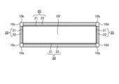
- FIG. 8 is a rear view of the casing 10 of the air cleaner 2 according to the second embodiment, showing an example of the external appearance when the conductive parts 20 are arranged on the four sides of the casing 10.
- FIG. 8 shows the air cleaner 2 viewed from the back side.
- FIG. 8 is a plan view, the conductive component 20 is hatched for ease of understanding.
- FIG. 8 shows the case 10 in which a conductive component 20 is attached to a stepped portion 101, which will be described later, as viewed from the back side.
- the conductive component 20 is made of a conductive material, and is disposed on the side surface of the casing 10 from the outside of the casing 10 to cover the side surface. That is, the conductive component 20 can be said to be a conductive portion 10g having conductivity. Therefore, it can be said that the air cleaner 2 in which the side surface of the casing 10 is covered with the conductive component 20 has the conductive part 10g having conductivity on the side surface of the casing 10. Thereby, the air cleaner 2 can shield the electric field extending from the casing 10 to the wall surface 500 with the conductive portion 10g, and prevent the occurrence of dirt on the wall surface 500 due to the electric field.
- the conductive component 20 is provided with an opening or a notch corresponding to the shape and size of the suction port 13 and the blowout port 14 in a portion corresponding to the suction port 13 and the blowout port 14, or And it is not arranged on the side of the part corresponding to the air outlet 14. Thereby, the conductive material disposed on the side surface of the casing 10 does not interfere with the functions of the inlet 13 and the outlet 14.
- Examples of the conductive material constituting the conductive component 20 include metal, conductive resin, and non-conductive resin coated with conductive paint.
- metal has a metallic luster unique to metal, and the appearance does not match with the resin that makes up the housing 10. For this reason, when the conductive component 20 is placed on the side surface of the casing 10 made of resin, the conductive component 20 made of metal stands out, and the design of the exterior of the air cleaner 2 deteriorates.
- the conductivity of the surface of the conductive component 20 becomes extremely small, so that the effect of using a conductive material for the conductive component 20 cannot be sufficiently obtained.
- the conductive component 20 is made to have a harmonious appearance between the side surface of the resin housing 10 and the conductive component 20. be able to.
- the air cleaner 2 can suppress the occurrence of dirt on the wall surface 500 due to the conductivity of the conductive component 20 and the conductivity of the conductive paint, while ensuring the aesthetic design of the exterior of the air cleaner 2. .
- Conductive paint is a paint in which conductive additives are mixed, and has conductivity. That is, the conductive paint is a paint that contains a conductive additive and has conductivity.
- An example of the paint is an epoxy polyester paint.
- Examples of conductive additives are conductive carbon, metal powders and metal oxide powders.
- the casing 10 has a step-shaped portion 101 that accommodates the conductive component 20 in the in-plane direction of the wall surface 500 on the inside of the casing 10 rather than on the side surface of the casing 10. Has it on the side.
- the conductive component 20 is attached to the stepped portion 101 on the side surface of the housing 10 .
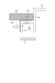
- FIG. 9 is an enlarged cross-sectional view showing the second side surface 10d and the periphery of the conductive component 20 in the housing 10 of the air cleaner 2 according to the second embodiment. Note that in FIG. 9, some hatching is omitted for ease of understanding. As shown in FIG. 9, a stepped portion 101 is formed at the end of the second side surface 10d of the housing 10 on the back surface 10f side.
- the step-shaped portion 101 has a first step-shaped portion 102 and a second step-shaped portion 103 that is bent and extends from the end of the first step-shaped portion 102 on the inside side of the casing 10 .
- the step-shaped portion 101 has an L-shape in which the first step-shaped portion 102 and the second step-shaped portion 103 are connected in a cross section perpendicular to the back surface 10f.
- the first step-shaped portion 102 is formed on the second side surface 10d in the direction perpendicular to the back surface 10f in the in-plane direction of the back surface 10f of the casing 10 facing the wall surface 500 when the air cleaner 2 is installed on the wall surface 500. It extends in a bent manner toward the inside of the casing 10 from an intermediate portion, and is parallel to the back surface 10f. That is, the in-plane direction of the first stepped portion 102 and the in-plane direction of the back surface 10f are parallel to each other. The in-plane direction of the back surface 10f is parallel to the in-plane direction of the wall surface 500.
- the second step-shaped portion 103 extends from the end of the first step-shaped portion 102 on the inside side of the casing 10 in a bent manner toward the back surface 10f, and is parallel to the second side surface 10d. That is, the in-plane direction of the second stepped portion 103 and the in-plane direction of the second side surface 10d are parallel to each other.
- the conductive component 20 includes a first conductive part 21 that contacts the first step-shaped part 102 and a first conductive part 21 that is bent and extends from one end of the first conductive part 21 and contacts the second step-shaped part 103. 2 conductive parts 22.
- the conductive component 20 has an L-shape in which the first conductive part 21 and the second conductive part 22 are connected in a cross section perpendicular to the back surface 10f.
- the conductive component 20 is fixed to the stepped portion 101 by screwing the first conductive portion 21 to the first stepped portion 102 of the stepped portion 101 using screws 40 .
- the conductive component 20 is provided for the purpose of shielding an electric field
- the first step-shaped portion 102 and the first conductive portion 21 and the second step-shaped portion 103 and the conductive portion 22 are not necessarily in contact with each other. There may be no gap, or there may be a gap.
- the first stepped portion 102 on the back side of the stepped portion 101 is also covered with the conductive component 20, and the conductive component 20 is fixed to the first stepped portion 102 with screws.
- the structure is said to be Thereby, in the air cleaner 2, the screws 40 are difficult to see from the user, and the design of the exterior of the air cleaner 2 can be ensured.
- first side surface 10c of the housing 10 also has the same configuration as the second side surface 10d described above.
- the conductive component 20 is in contact with the wall surface 500 when the air cleaner 2 is installed on the wall surface 500. That is, as shown in FIG. 9, the end portion 24 of the conductive component 20 in the direction perpendicular to the back surface 10f of the housing 10 is in contact with the wall surface 500 when the air cleaner 2 is installed on the wall surface 500.
- the end portion 24 of the conductive component 20 is brought into contact with the wall surface 500, thereby bringing the conductive component 20 into contact with the wall surface 500 and grounding, giving the conductive component 20 an electric field shielding effect.
- the air purifier 2 it is possible to suppress the generation of an electric field between the housing 10 and the wall 500 due to the electric potential generated when the housing 10 is charged, and the generation of dirt on the wall surface 500 can be suppressed. Can be suppressed.
- FIG. 10 is an enlarged sectional view showing a modification of another conductive component 20a of the air cleaner 2 according to the second embodiment. Note that in FIG. 10, some hatching is omitted for ease of understanding.
- FIG. 10 is a diagram corresponding to FIG. 9, and shows a state in which another conductive component 20a is screwed to the stepped portion 101.
- the other conductive component 20a has a third conductive portion 23 that contacts the wall surface 500 and the back surface 10f of the casing 10 when the air cleaner 2 is installed on the wall surface 500. different.
- the conductive part 20a has a better contact with the wall surface 500 than the conductive part 20 without the third conductive part 23 when the air cleaner 2 is installed on the wall surface 500. A wide contact area is ensured.
- the contact resistance between the casing 10 and the wall surface 500 can be reduced.
- the air cleaner 2 using the third conductive part 23 can more effectively suppress the electric field due to the potential generated when the casing 10 is charged, and the generation of dirt on the wall surface 500. can be suppressed more effectively and with high reliability.
- FIG. 11 is an enlarged cross-sectional view showing the second side surface 10d and the periphery of the other conductive component 20a in the casing 10 of a modified example of the air cleaner 2 according to the second embodiment.
- a metal mounting bracket 400 it is preferable to fix the casing 10 to the wall surface 500.
- the installation fitting 400 When installing the air cleaner 2 on the wall surface 500 using the installation fitting 400, the installation fitting 400 is first screwed onto the wall surface 500. At this time, the installation fitting 400 is screwed to the wall surface 500 so as to be in close contact with the wall surface 500. Next, the casing 10 is hooked onto the installation fittings 400. Thereafter, the casing 10 is fixed to the installation fitting 400 with screws. At this time, the casing 10 is screwed so that the third conductive part 23 of the other conductive component 20a is tightly sandwiched between the back surface 10f of the casing 10 and the installation fitting 400. In this case, the installation fitting 400 and the other conductive component 20a, or the wall surface 500 and the other conductive component 20a may be brought into close contact with each other by tightening the screws.
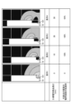
- FIG. 12 is a diagram showing the simulation results of the electric field strength of the wall surface 500 on which the air cleaner 2 according to the second embodiment is installed.
- the conductive component 20 is not shown in the simulation shown in FIG. 12, the conductive component 20 is placed in the stepped portion 101 as in the case of FIG. It is in contact with the wall surface 500.
- the simulation was performed by changing the length of the conductive component 20 into multiple types.
- the length of the conductive component 20 is the length from the wall surface 500 to the end of the conductive component 20 on the front surface 10e side of the housing 10 in the direction perpendicular to the wall surface 500.
- the length of the conductive component 20 was set to 0 mm.
- the length of the conductive component 20 was 18 mm.
- the length of the conductive component 20 was 28 mm.
- the length of the conductive component 20 was 38 mm.
- the dimension of the first stepped portion 102 was 12 mm.
- the dimensions of the second stepped portion 103 were changed in accordance with the dimensions of the conductive component 20.
- the discharge voltage of the corona discharge in the electrostatic precipitator 120 which is the elementary cause of the first cause of the wall surface 500 being charged, is set to 4 kV or more and 10 kV or less, and the second cause of the above-mentioned wall surface 500 being charged.
- the thinner the hatching the stronger the electric field strength.
- the darker the hatching the weaker the electric field strength.
- the representative point is a measurement point of the electric field strength on the wall surface 500, and is located on the surface of the wall surface 500 at a distance of 10 mm from the side surface of the casing 10.
- the electric field strength on the wall surface 500 could be reduced by 50% under condition 2 compared to condition 1. Further, as the simulation conditions are changed from Condition 1 to Condition 2, Condition 3, and Condition 4, that is, as the length of the conductive component 20 becomes longer, the electric field strength of the wall surface 500 at the representative point becomes smaller. , it was found that the shielding effect of the electric field becomes higher. From this, by setting the length of the conductive component 20 from the wall surface 500 to 18 mm or more, the arrangement range of the conductive component 20 is set at an effective location in order to obtain the effect of preventing the generation of dirt on the wall surface 500. It has been found that the electric field generated between the casing 10 and the wall surface 500 can be efficiently suppressed and the generation of stains on the wall surface 500 can be prevented.
- grounding work is not required and the wall surface 500 on which the air purifier 1 is installed can be This has the effect of preventing stains.
- the arrangement range of the conductive component 20 is limited to an effective location, and the casing 10 and the wall surface 500 are efficiently connected. It is possible to prevent an electric field from occurring during the process, thereby preventing the wall surface 500 from becoming dirty.
- FIG. 13 is a configuration diagram showing an outline of the configuration of the air cleaner 3 according to the third embodiment.
- the air purifier 3 according to the third embodiment the same components as the air purifiers 1 and 2 according to the first and second embodiments are given the same reference numerals as the air purifiers 1 and 2, and detailed explanations are given. The explanation will be omitted.
- the air cleaner 3 is installed on the ceiling 600 with a portion of the air cleaner 3 embedded in the attic through an opening 602 in the ceiling 600. Therefore, the air cleaner 3 basically has the same configuration as the air cleaners 1 and 2 described above, but differs from the air cleaners 1 and 2 in the arrangement of each component and the shape of the casing 10.
- a partial area 10f1 of the back surface 10f of the housing 10 is used as an installation part for installing the housing 10 on the ceiling 600.
- the air cleaner 3 is installed on the ceiling 600 without using the installation brackets used in the first embodiment, but in a part of the attic with high mechanical strength, such as the edge 603.
- a partial area 10f1 of the back surface 10f of the casing 10 is fastened to the edge 603 with screws 603 and installed from the inside of the air cleaner 3.
- FIG. 14 is an enlarged sectional view showing the vicinity of the conductive component 27 in the housing 10 of the air cleaner 3 according to the third embodiment.
- the casing 10 of the air cleaner 3 does not have the stepped portion 101 shown in the second embodiment.
- the conductive component 27 according to the third embodiment has the same function as the conductive component 20 described above.
- the conductive component 27 includes a fourth conductive part 25 arranged perpendicularly to the ceiling surface 601, and a part of the rear surface 10f of the housing 10 that extends in a bent manner from one end of the fourth conductive part 25.
- the fifth conductive portion 26 is sandwiched between the lower region 10f1 and the ceiling surface 601.
- Ceiling surface 601 is an installation surface on which air cleaner 3 according to the third embodiment is installed.
- the in-plane direction of the ceiling surface 601 is perpendicular to the in-plane direction of the side surface 10 h of the housing 10 . That is, the fourth conductive portion 25 is arranged parallel to the side surface 10h of the housing
- the conductive component 27 according to the third embodiment has an L-shape in which the fourth conductive part 25 and the fifth conductive part 26 are connected in a cross section perpendicular to the back surface 10f.
- the fifth conductive portion 26 is screwed to the edge 603 together with the partial area 10f1 of the back surface 10f of the housing 10 by screws 604. Therefore, in the state where the air cleaner 3 is installed on the ceiling surface 601, the conductive component 27 according to the third embodiment has the fourth conductive part 25 parallel to the side surface 10h of the housing 10, and the air cleaner The fifth conductive portion 26 is in contact with the ceiling surface 601 and a partial region 10f1 of the back surface 10f of the housing 10 when the machine 3 is installed on the ceiling surface 601.
- Embodiment 4 air cleaners 1, 2, and 3 as shown in FIGS. 3, 7, and 13 have been described with respect to configurations that can suppress or prevent the occurrence of dirt on the installation surface.
- the configurations shown in FIGS. 3, 7, and 13 can also be applied to an air conditioner with an air cleaning function and a ventilation fan with an air cleaning function.
- the same effect as above can be obtained when the above-mentioned configuration that can suppress or prevent the generation of dirt on the installation surface is applied to equipment such as an air conditioner with an air purification function and a ventilation fan with an air purification function. .
- Air purifier 10 Housing, 10a Top surface, 10b Bottom surface, 10c First side, 10d Second side, 10e Front, 10f Back, 10g Conductive part, 10h Side, 11 Housing main body, 12 Front panel , 13 Suction port, 14 Air outlet, 20, 27 Conductive parts, 20a Other conductive parts, 21 First conductive part, 22 Second conductive part, 23 Third conductive part, 24 End part, 25 th 4 conductive part, 26 fifth conductive part, 40, 604 screw, 45 air flow, 100 dust collection part, 101 step shape part, 102 first step shape part, 103 second step shape part, 110 mesh filter, 120 Electrical dust collector, 121 Discharge part positive electrode, 122 Discharge part negative electrode, 123 Discharge area, 124 Dust, 130 Deodorizing filter, 150 Air passage wall, 200 Air blower, 201 Fan casing, 202 Fan, 203 Motor, 204 Bell mouth, 300 Circuit part, 301 Strong electric circuit board, 302 Low electric circuit board, 303 Sheet metal case, 400 Installation bracket, 500 Wall surface, 501 Wall
Landscapes
- Engineering & Computer Science (AREA)
- Chemical & Material Sciences (AREA)
- Combustion & Propulsion (AREA)
- Mechanical Engineering (AREA)
- General Engineering & Computer Science (AREA)
- Electrostatic Separation (AREA)
Priority Applications (3)
| Application Number | Priority Date | Filing Date | Title |
|---|---|---|---|
| JP2024528157A JP7832324B2 (ja) | 2022-06-21 | 2022-06-21 | 空気清浄機、空気調和機および換気扇 |
| PCT/JP2022/024758 WO2023248358A1 (ja) | 2022-06-21 | 2022-06-21 | 空気清浄機、空気調和機および換気扇 |
| TW112119741A TWI866237B (zh) | 2022-06-21 | 2023-05-26 | 空氣清淨機、空氣調和機及換氣扇 |
Applications Claiming Priority (1)
| Application Number | Priority Date | Filing Date | Title |
|---|---|---|---|
| PCT/JP2022/024758 WO2023248358A1 (ja) | 2022-06-21 | 2022-06-21 | 空気清浄機、空気調和機および換気扇 |
Publications (1)
| Publication Number | Publication Date |
|---|---|
| WO2023248358A1 true WO2023248358A1 (ja) | 2023-12-28 |
Family
ID=89379607
Family Applications (1)
| Application Number | Title | Priority Date | Filing Date |
|---|---|---|---|
| PCT/JP2022/024758 Ceased WO2023248358A1 (ja) | 2022-06-21 | 2022-06-21 | 空気清浄機、空気調和機および換気扇 |
Country Status (3)
| Country | Link |
|---|---|
| JP (1) | JP7832324B2 (https=) |
| TW (1) | TWI866237B (https=) |
| WO (1) | WO2023248358A1 (https=) |
Citations (10)
| Publication number | Priority date | Publication date | Assignee | Title |
|---|---|---|---|---|
| JPS55121336A (en) * | 1979-03-12 | 1980-09-18 | Matsushita Seiko Co Ltd | Air clarifying ventilating device |
| JPS5725748U (https=) * | 1980-07-18 | 1982-02-10 | ||
| JPS6266721U (https=) * | 1985-10-15 | 1987-04-25 | ||
| JPH0281637U (https=) * | 1988-12-02 | 1990-06-25 | ||
| JPH02100657U (https=) * | 1989-01-21 | 1990-08-10 | ||
| JPH05177151A (ja) * | 1991-12-27 | 1993-07-20 | Daikin Ind Ltd | 空気清浄機の取付け構造 |
| JPH06254439A (ja) * | 1993-03-08 | 1994-09-13 | Matsushita Seiko Co Ltd | 空気清浄機 |
| JP2011072891A (ja) * | 2009-09-30 | 2011-04-14 | Daikin Industries Ltd | 集塵装置 |
| JP2015167927A (ja) * | 2014-03-07 | 2015-09-28 | 株式会社富士通ゼネラル | 電気集塵装置並びにそれを利用した空気調和機 |
| JP2018096657A (ja) * | 2016-12-16 | 2018-06-21 | 三菱電機株式会社 | 空気清浄機 |
Family Cites Families (5)
| Publication number | Priority date | Publication date | Assignee | Title |
|---|---|---|---|---|
| JP5067084B2 (ja) * | 2007-09-11 | 2012-11-07 | パナソニック株式会社 | 空気清浄フィルタおよび空気清浄装置 |
| JP2009208021A (ja) * | 2008-03-05 | 2009-09-17 | Sanyo Electric Co Ltd | 吸水装置及び霧化装置 |
| JP2009286893A (ja) * | 2008-05-29 | 2009-12-10 | Idemitsu Kosan Co Ltd | ポリピロール系複合体、導電性塗料、導電性膜および導電体 |
| EP3115113A4 (en) * | 2014-03-07 | 2017-11-08 | Fujitsu General Limited | Electrostatic precipitator and air conditioner using same |
| CN112325393A (zh) * | 2019-08-05 | 2021-02-05 | 青岛海尔空调器有限总公司 | 空调室内机和空调器 |
-
2022
- 2022-06-21 WO PCT/JP2022/024758 patent/WO2023248358A1/ja not_active Ceased
- 2022-06-21 JP JP2024528157A patent/JP7832324B2/ja active Active
-
2023
- 2023-05-26 TW TW112119741A patent/TWI866237B/zh active
Patent Citations (10)
| Publication number | Priority date | Publication date | Assignee | Title |
|---|---|---|---|---|
| JPS55121336A (en) * | 1979-03-12 | 1980-09-18 | Matsushita Seiko Co Ltd | Air clarifying ventilating device |
| JPS5725748U (https=) * | 1980-07-18 | 1982-02-10 | ||
| JPS6266721U (https=) * | 1985-10-15 | 1987-04-25 | ||
| JPH0281637U (https=) * | 1988-12-02 | 1990-06-25 | ||
| JPH02100657U (https=) * | 1989-01-21 | 1990-08-10 | ||
| JPH05177151A (ja) * | 1991-12-27 | 1993-07-20 | Daikin Ind Ltd | 空気清浄機の取付け構造 |
| JPH06254439A (ja) * | 1993-03-08 | 1994-09-13 | Matsushita Seiko Co Ltd | 空気清浄機 |
| JP2011072891A (ja) * | 2009-09-30 | 2011-04-14 | Daikin Industries Ltd | 集塵装置 |
| JP2015167927A (ja) * | 2014-03-07 | 2015-09-28 | 株式会社富士通ゼネラル | 電気集塵装置並びにそれを利用した空気調和機 |
| JP2018096657A (ja) * | 2016-12-16 | 2018-06-21 | 三菱電機株式会社 | 空気清浄機 |
Also Published As
| Publication number | Publication date |
|---|---|
| JPWO2023248358A1 (https=) | 2023-12-28 |
| TWI866237B (zh) | 2024-12-11 |
| JP7832324B2 (ja) | 2026-03-17 |
| TW202400942A (zh) | 2024-01-01 |
Similar Documents
| Publication | Publication Date | Title |
|---|---|---|
| CA1204391A (en) | Air cleaning apparatus | |
| CN102428324B (zh) | 离子产生装置 | |
| JP5992715B2 (ja) | イオン発生装置 | |
| JP4853604B2 (ja) | 空気調和機 | |
| WO2023248358A1 (ja) | 空気清浄機、空気調和機および換気扇 | |
| CN209549712U (zh) | 静电除油烟装置 | |
| JP2026071351A (ja) | 空気清浄機、空気調和機および換気扇 | |
| CN105855051A (zh) | 静电集尘装置和空气净化器 | |
| JP4411356B1 (ja) | イオン検出装置及びそれを備えたイオン発生装置 | |
| JP7802034B2 (ja) | 空気清浄機 | |
| JP7822343B2 (ja) | 空気清浄機 | |
| JP7630652B2 (ja) | 空気清浄機 | |
| WO2025009068A1 (ja) | 空気清浄機 | |
| JP7799652B2 (ja) | 空気清浄機 | |
| JPH06226139A (ja) | 空気清浄機 | |
| CN108198589A (zh) | 一种用于仪器仪表的防尘装置 | |
| JP2024160810A (ja) | 空気清浄機 | |
| JP2024160811A (ja) | 空気清浄機 | |
| CN218379821U (zh) | 离子发生器、过滤组件和空调 | |
| JP3644941B2 (ja) | イオン風発生用電源装置 | |
| JPWO2023248358A5 (https=) | ||
| JP7630653B2 (ja) | 空気清浄機 | |
| JPWO2023062702A5 (https=) | ||
| JP7679943B1 (ja) | 空気清浄装置 | |
| CN103635753B (zh) | 空调机 |
Legal Events
| Date | Code | Title | Description |
|---|---|---|---|
| 121 | Ep: the epo has been informed by wipo that ep was designated in this application |
Ref document number: 22947920 Country of ref document: EP Kind code of ref document: A1 |
|
| WWE | Wipo information: entry into national phase |
Ref document number: 2024528157 Country of ref document: JP |
|
| NENP | Non-entry into the national phase |
Ref country code: DE |
|
| 122 | Ep: pct application non-entry in european phase |
Ref document number: 22947920 Country of ref document: EP Kind code of ref document: A1 |