WO2023243285A1 - 演出出力玩具及び玩具別体 - Google Patents
演出出力玩具及び玩具別体 Download PDFInfo
- Publication number
- WO2023243285A1 WO2023243285A1 PCT/JP2023/018201 JP2023018201W WO2023243285A1 WO 2023243285 A1 WO2023243285 A1 WO 2023243285A1 JP 2023018201 W JP2023018201 W JP 2023018201W WO 2023243285 A1 WO2023243285 A1 WO 2023243285A1
- Authority
- WO
- WIPO (PCT)
- Prior art keywords
- toy
- color
- sheet
- colors
- separate
- Prior art date
- Legal status (The legal status is an assumption and is not a legal conclusion. Google has not performed a legal analysis and makes no representation as to the accuracy of the status listed.)
- Ceased
Links
Images


Classifications
-
- A—HUMAN NECESSITIES
- A63—SPORTS; GAMES; AMUSEMENTS
- A63H—TOYS, e.g. TOPS, DOLLS, HOOPS OR BUILDING BLOCKS
- A63H33/00—Other toys
- A63H33/22—Optical, colour, or shadow toys
-
- A—HUMAN NECESSITIES
- A63—SPORTS; GAMES; AMUSEMENTS
- A63H—TOYS, e.g. TOPS, DOLLS, HOOPS OR BUILDING BLOCKS
- A63H33/00—Other toys
-
- A—HUMAN NECESSITIES
- A63—SPORTS; GAMES; AMUSEMENTS
- A63H—TOYS, e.g. TOPS, DOLLS, HOOPS OR BUILDING BLOCKS
- A63H5/00—Musical or noise- producing devices for additional toy effects other than acoustical
Definitions
- Patent Document 1 proposes a moving toy that outputs light and sound from the toy body depending on the type of removable article attached to the toy body.
- the present invention provides a novel mechanism for realizing a performance, for example, in a performance output toy.
- the present invention is, for example, a production output toy, which includes a toy main body having a light emitting section capable of emitting light in a plurality of colors and a control section controlling production using the light emitting section, and a toy body that is detachable from the toy main body. and one or more separate toy bodies that are capable of transmitting light emitted from the light emitting part when attached to the toy main body, and each of the one or more separate toy bodies has complementary colors that are different from each other and that transmit light emitted from the light emitting part when attached to the toy main body.
- the present invention is characterized by comprising a presentation member formed using the same method.
- the present invention provides a separate toy that is attached to a toy main body, and includes, for example, a light emitting section that can emit light in a plurality of colors, and a control section that controls effects using the light emitting section,
- the present invention is characterized by comprising a presentation member formed using mutually different complementary colors that transmits the irradiated light from the light emitting section when attached to the device.
- FIG. 3 is a diagram showing how the presentation member is attached and detached according to an embodiment.
- FIG. 3 is a diagram illustrating a configuration example of a complementary color gimmick according to an embodiment.
- FIG. 3 is a diagram illustrating a configuration example of a complementary color gimmick according to an embodiment.
- FIG. 3 is a diagram showing correspondence information stored in a storage unit and a production pattern realized by a program according to an embodiment.
- 5 is a flowchart showing a processing procedure of a control unit according to an embodiment.
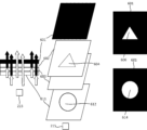
- FIG. 1(a) shows a front external appearance of the performance output toy 100
- FIG. 1(b) shows a plan view of the external appearance of the performance output toy 100. Note that the up and down, left and right, and front and back arrows indicate the direction of the performance output toy in the figure, and the same applies to other figures.
- the performance output toy 100 includes a toy main body 101 and separate toy bodies 102 and 103.
- the production output toy 100 according to this embodiment will be described as a buckle attached to a belt.
- the toy main body 101 is composed of a base 111 and a main body 112, and separate toy bodies 102 and 103 are attached to the main body 112.
- the main body part 112 is configured to be rotatable relative to the base part 111, and can rotate relative to the base part 111, including the separate toys 102 and 103 attached to the main body part 112.
- the toy separate bodies 102 and 103 can be individually attached to and detached from the toy body 101, and many variations may be provided as optional devices of the production output toy.
- the performance output toy 100 outputs various performances using light, sound, display, vibration, etc., depending on the separate toys 102 and 103 attached to the toy main body 101.
- the toy main body 101 is provided with a light emitting section that can emit light in multiple colors and a control section for controlling effects, and outputs various effects depending on the attached toy. do.
- the separate toys 102 and 103 are equipped with production members having a simple structure to enable various productions, but are also equipped with a light emitting section and a control section like the toy main body 101. It can be manufactured relatively cheaply. Therefore, many variations of separate toys can be easily provided in order to realize a variety of performance patterns.
- the separate toys 102 and 103 may be provided with a light emitting section, a sounding section, a control section, and the like.
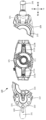
- FIG. 2 shows the toy main body 101 and separate toy bodies 102 and 103 before attachment.
- the toy main body 101 includes a production section 211, mounting sections 212a and 212b, and detection sections 213a and 213b.
- the production unit 211 is provided with devices related to production, particularly a light emitting unit, a sensor, and a switch. Details of the production section 211 will be described later using FIG. 3.
- Separate toys 102 and 103 can be attached to the attachment parts 212a and 212b, respectively. Note that any separate toy 102, 103 may be attached to each attachment part 212a, 212b. Further, two separate toys of the same type, for example, two separate toys 102, may be attached to the mounting portions 212a and 212b.
- the detection units 213a and 213b individually recognize the separate toys attached to the attachment units 212a and 212b, respectively.
- the detection units 213a and 213b are sensors that read identification units 225 and 235 provided on separate toys, which will be described later.
- the sensor any type of sensor can be used depending on the form of the identification section.
- various sensors such as an infrared sensor, a laser sensor, a camera sensor, a contact type sensor, an ultrasonic sensor, and a radio wave sensor can be used.
- the separate toy 102 includes a grip 221 , a rotating member 222 , a presentation member 223 , a switch 224 , and an identification section 225 .
- the grip 221 is held by the operator when rotating the base 111 of the toy body 101.
- a switch 224 is provided on the grip 221, and when pressed by the operator, a production output can be activated.
- the rotating member 222 is rotatably attached, and when rotated while attached to the toy body 101, a switch 214a provided on the toy body 101, which will be described later, can be operated.
- the presentation member 223 is formed in a semicircular shape, and holds therein at least two color formation layers of mutually different colors that are in a complementary color relationship and are superimposed.
- overlapping is not limited to the formation layers of two colors being arranged in close contact with each other, but the formation layers of another color being sandwiched between the formation layers of two colors. It can also include form. Furthermore, when superimposing two colored formation layers, two sheets (two sheets) each formed of two different colors may be superimposed, or one sheet (one sheet) may be superimposed. It may be formed by overlapping two color forming layers.
- the performance member is made of a member that can transmit light, and can transmit light emitted from light emitting sections 215b and 215c, which will be described later, provided on the toy main body 101. At that time, a variety of effects can be achieved by changing (absorbing) the color of the irradiated light using a sheet installed inside.
- identification section 225 identification information for identifying the separate toy 102 is formed.
- the identification section 225 is formed in any form according to the method of the detection sections 213a and 213b, and includes, for example, a numerical value, a character string, a bar code, etc. representing identification information, or a physical unevenness. It may be formed as an IC tag, an infrared transmitter, or the like.
- the separate toy 103 includes a grip 231, a presentation member 233, and an identification section 235.
- the grip 231 is a member that is held by the operator similarly to the grip 221, and the grip 231 itself is formed to be rotatable. By rotating the grip 231 itself, the production output can be activated.
- the effect member 233 has the same configuration as the effect member 223, and when the toy separate bodies 102 and 103 are attached to the toy main body 101, the effect member 233 comes into contact with the effect member 223 to form a circular effect part.
- the identification unit 235 has a similar configuration to the identification unit 225.
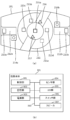
- FIG. 3(a) shows an external plan view of the toy main body 101.
- FIG. 3(b) shows a block diagram of the control configuration of the toy main body 101.
- the toy main body 101 includes, in addition to the above-described detection units 213a and 213b, detection units 216 and 217, switches 214a and 214b, and light emitting units 215a to 215e as components related to production output. It further includes: The detection units 216, 217 and the light emitting units 215a to 215e are provided inside the presentation unit 211. The detection unit 216 detects that the main body portion 112 of the toy main body 101 has rotated with respect to the base portion 111.
- the detection unit 216 is, for example, a push-down type sensor, and the detection unit 216 is pressed down every time the main body 112 rotates 180 degrees with respect to the base 111, and outputs a detection signal to the control unit 301, which will be described later.
- the detection unit 217 detects its identification information.
- the detection unit 217 may have the same configuration as the detection units 213a and 213b. Further, the production output toy 100 may be configured to output production according to the detected identification information when the circular production member is fitted.
- the switch 214a is a switch that is pressed down by clockwise or counterclockwise rotation of the rotating member 222 of the separate toy 102.
- the switch 214b is a switch that is pressed down when the grip 231 of the separate toy 103 is rotated.
- the light emitting units 215a to 215e can emit light in a plurality of colors, and may employ full-color LEDs (light emitting diodes), for example.
- the light emitting units 215a to 215e may be controlled individually or may be controlled in a unified manner. Note that in the case of individual control, the timing and color of light emission can be individually controlled, so more diverse effects can be realized.
- the light emitting section 215a is arranged inside a circular shape located at the center of the presentation section 211. When the circular effect member is fitted, it emits light under the control of a control section, which will be described later.
- the light emitting parts 215b and 215c are disposed below the presentation member 223 of the separate toy 102 when the separate toy 102 is attached to the toy main body 101, and by emitting light, the sheet provided on the presentation member 223 is illuminated. It is possible to output the performance by passing through the .
- the light emitting parts 215d and 215e are disposed below the presentation member 233 of the separate toy 103 when the separate toy 103 is attached to the toy main body 101, and by emitting light, the sheet provided on the presentation member 233 is illuminated. It is possible to output the performance by passing through the .
- the toy main body 101 includes a control section 301, a storage section 302, a power supply section 303, a sensor group 304, an LED group 305, a switch group 306, and a speaker 307 as control components.
- the sensor group 304 corresponds to the detection units 213a, 213b, 216, and 217.
- the LED group 305 corresponds to the light emitting sections 215a to 215e.
- the control unit 301 is constituted by a microprocessor or the like, and controls the performance output of the performance output toy 100 by reading and executing a program stored in the storage unit 302.
- the storage unit 302 includes various memories such as ROM (Read Only Memory) and RAM (Random Access Memory), and the control unit 301 It stores various data such as a program executed by the speaker 307, sound data outputted from the speaker 307, and correspondence information linking identification information of a separate toy with information of a program to be executed. Details of the program and corresponding information will be described later.
- the power supply section 303 supplies power to the toy main body 101, and is preferably realized by a battery in order to maintain portability, but the present invention is not limited to this, and any type of power supply may be applied. be able to.
- the battery may be of a rechargeable type.
- the sensor group 304 outputs a detection signal to the control unit 301 in response to detection by each sensor (detection unit).
- the LED group 305 emits light in a predetermined color and at a predetermined timing according to instructions from the control unit 301.
- the switch group 306 outputs a signal to the control unit 301 at the timing when each switch is pressed.
- the speaker 307 is controlled by the control unit 301 and outputs sound according to the sound data stored in the storage unit 302.
- the separate toy body 102 is attached to the toy main body 101, as shown in FIG. 4(b).
- the rotating member 222 can be rotated as shown by the dotted arrow 401 or the switch 224 can be operated.
- an operation signal is transmitted from each switch 224, 214a to the control unit 301, and a performance output corresponding to the operation is activated.
- only one separate toy 102 is attached to the toy main body 101.
- control section 301 controls the light emitting sections 215a to 215c to emit light and the light emitting sections 215d and 215e to not emit light. It's okay.
- control unit 301 may control all the light emitting units 215a to 215e to emit light even when one separate toy is attached.
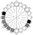
- FIG. 5 shows an example of a hue wheel.
- FIG. 5 shows an example of a hue wheel of 20 colors.
- color variations are represented by different shading.
- FIG. 5 shows a hue circle based on the Munsell color system as an example of a hue circle.
- the Munsell color system adds intermediate hues (yellow-red YR, yellow-green GY, blue-green BG, blue-violet PB, red-violet RP) to the five basic hues (red R, yellow Y, green G, blue B, purple P). It consists of 20 hues.
- two colors that are directly opposite have a complementary color relationship.
- complementary colors include colors adjacent to the opposite color. For example, red and green are complementary colors.
- red (5R) and blue-green (5BG) indicated by a dotted line 501 are complementary colors.
- yellow-red (10YR) and blue (10B) indicated by a dotted line 502 are complementary colors.
- complementary colors When complementary colors are mixed together, it becomes a gray color (achromatic color) that is very close to black.
- the performance output toy 100 according to the present embodiment realizes various performance patterns using a combination of two complementary colors.
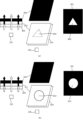
- FIG. 6A shows a configuration for explaining sheets of two complementary colors.
- FIG. 6B shows a structure in which sheets of two complementary colors are integrated, and shows the structure of the sheet member according to this embodiment.
- a configuration will be described in which two sheets formed using two complementary color paints (printed on a transparent sheet) are overlapped, but the present invention is not limited. There is no intention. For example, it may be formed using two colors of paint on one side of one sheet and the other side that is the back side of the one sheet. Alternatively, the respective paints may be printed (coated) on one side of one sheet. Therefore, when one sheet is used, a plurality of layers corresponding to each sheet described below will be formed.
- FIG. 6A(a) shows the presentation configuration of the first color among the two complementary colors.
- 215 indicates one of the light emitting sections 215b to 215e.
- the light emitting unit 215 is, for example, a full color LED, and is capable of emitting light in a plurality of colors.
- a plurality of transparent sheets (sheets that can transmit light) are arranged above the light emitting section 215.
- Sheet 601 is a black transparent sheet.
- the sheet 602 is a sheet formed using a second color paint that is complementary to the first color.
- a transparent region 604 having an arbitrary shape and outlined in white is formed on the surface of the sheet 602 on which the second color paint is formed.
- the outlined transparent area indicates a colorless and transparent area.
- the sheet 603 is a sheet for diffusing the irradiated light from the light emitting section 215.
- Each of the sheets 601 to 603 is a transparent sheet made of a resin such as polycarbonate (PC), polyethylene terephthalate (PET), or polypropylene (PP).
- the sheet 602 is formed (printed) using paints of two complementary colors.
- a colorless and transparent PC sheet printed with a second color paint is used.
- any type of paint may be used as long as it does not significantly reduce the light transmittance through the sheet.
- a sheet that diffuses light is used as the sheet 603, it is not necessary to specifically diffuse light, and for example, a transparent PET sheet may be used.
- a sheet formed using paint is described as an example, but the sheet is not limited to this, and for example, a sheet formed using a black or second color resin material that can transmit light. A sheet may also be used.
- These plurality of sheets (or plurality of layers) 601, 602, and 603 are arranged in an overlapping manner in this order from above.
- a colorless and transparent sheet may be coated with paint in the order of the second color and then black.
- the light emitting section 215 emits light in the first color from the bottom of these sheets 601 to 603.
- the first color irradiation light from the light emitting unit 215 is first diffused by the sheet 603, and then passes through the second color sheet 602 having a complementary color relationship.
- the second color sheet 602 when the irradiation light of the first color passes through the second color sheet having a complementary color relationship, it changes to gray (achromatic) light.
- the portion that has changed to gray (achromatic color) due to the complementary color relationship cannot be clearly seen, and passes through the outlined transparent area 604 of the sheet 602 without being affected by the complementary color relationship.
- the first color of light is projected. Therefore, the first color light is projected onto the black sheet 601, and an arbitrary shape 606 is formed. That is, the sheet 601 is an example of a display section on which effects are output.
- FIG. 6A(b) shows a presentation configuration of a second color that is complementary to the first color.
- the light emitting unit 215 emits light in a second color different from the first color among two complementary colors.
- a first color sheet 611 is arranged between the sheets 601 and 603.
- the sheet 611 is formed in a first color, and a transparent region 612 in an arbitrary shape is formed on a part of its forming surface.
- a sheet formed using paint is described as an example, but the sheet is not limited to this, and for example, a sheet formed using a black or first color resin material that can transmit light. A sheet may also be used.
- the light emitting section 215 emits light in the second color from the bottom of these sheets 601, 611, and 603.
- the second color irradiation light from the light emitting unit 215 is first diffused by the sheet 603, and then passes through the first color sheet 611 having a complementary color relationship.
- the sheet 611 of the first color when the irradiated light of the second color passes through the sheet of the first color having a complementary color relationship, it changes to gray (achromatic) light.
- the irradiation light of the second color passes through the white transparent area 612 of the sheet 611 of the first color while maintaining the second color.
- the irradiated light that has passed through the sheet 611 forms the above arbitrary shape with the second color light. Thereafter, those irradiated lights reach the black sheet 601.
- the black sheet 601 the part that has changed to gray (achromatic color) due to the influence of the complementary color relationship cannot be clearly seen, and passes through the outlined transparent area 612 of the sheet 611 without being affected by the complementary color relationship.
- the second color light is projected. Therefore, the second color light is projected onto the black sheet 601, and an arbitrary shape 614 is formed.
- each color of paint may be formed on one side of a colorless transparent sheet, or one side and the other side which is the back side of the one side. They may be formed using different colored paints. For example, a first color, a second color, and black paint may be layered on a colorless and transparent sheet, or a second color, black paint may be layered on one side of a colorless and transparent sheet, and a first color on the other side. Can be formed using colored paint. Note that the order of arrangement of the first color and second color layers is not particularly limited. Although the black layer is not essential, it is preferable to provide it because it can hide the first and second color layers.
- the black layer be provided above the first and second color layers.
- the complementary color gimmick when realizing the complementary color gimmick with one sheet, it can be realized by forming a layer printed with colorless and transparent paint as a buffer area corresponding to the sheet 603. By realizing the complementary color gimmick on one sheet, it is possible to save space and save costs.
- the color of the light emitted by the light emitting unit 215 can be outputted in two colors and in different shapes in a simple configuration in which a plurality of transparent sheets (or a plurality of layers) are superimposed. This is achieved by switching.
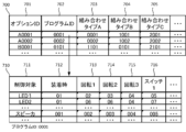
- a table 700 shown in FIG. 7 is information stored in the storage unit 302, and shows correspondence information that links identification information of a separate toy and information of a program to be executed.
- Reference numeral 701 indicates an option ID uniquely assigned to each toy.
- the option ID is identification information that can be obtained by reading the identification section 225 when the separate toy 102 is attached to the toy main body 101, for example.
- This program is a program for controlling production output.
- Table 710 shows an image of a performance pattern realized by one program stored in storage unit 302.
- the performance pattern realized by the program ID "0001" when each trigger occurs is shown.
- Reference numeral 711 indicates a control target at the time of outputting the effect.
- the controlled objects include devices used for outputting effects, such as LEDs and speakers. Other devices may also be included, such as a vibrator that outputs vibrations.
- 712 to 716 indicate identification numbers of production patterns when each trigger occurs.
- one program includes execution programs corresponding to various performance patterns as defined in table 710.
- the control unit 301 executes a corresponding effect pattern included in the program when each trigger occurs.
- Each trigger includes the time of attachment 712, the occurrence of various rotations, and the time of switch operation.
- rotation 1 at 713 indicates a trigger that occurs every time the body portion 112 rotates 180 degrees relative to the base portion 111.
- Reference numeral 714 indicates a trigger that occurs when the switch 214a is operated by rotating the rotating member 222.
- Reference numeral 715 indicates a trigger that occurs when the switch 214b is operated by rotating the grip 231.
- 716 indicates a trigger that occurs when the switch 224 is operated.
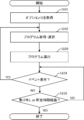
- the control unit 301 determines whether a new event has occurred. As shown in table 710, new events include detection of rotation, operation of a switch, and the like. When a new event occurs, the control unit 301 returns the process to S102 and selects a production pattern corresponding to the corresponding event. Since the subsequent processing is as described above, the explanation will be omitted.
- the production output toy includes a toy main body that has a light emitting section that can emit light in a plurality of colors, a control section that controls production using the light emitting section, and and one or more detachable toy bodies.
- the one or more separate toys include presentation members formed using complementary colors that are different from each other and that transmit the irradiation light from the light emitting part when attached to the toy main body.
- the production member holds at least two complementary colors in a superimposed manner (the production output toy described in 1).
- the control unit causes the light emitted from the light emitting unit to emit light in a complementary color to each of the two superimposed colors of the one or more separate toys attached to the toy body to produce an effect.
- the production output toy according to (2) characterized in that the production output toy is controlled.
- Transparent regions of different shapes are formed on the formation surfaces on which the superimposed two colors are formed, and the transparent regions maintain their colors by the complementary color irradiation light emitted from the light emitting part. 3.
- the sheet member includes two sheets, the first sheet of the two sheets is formed using a first color of the paint of the two colors, and the first of the two sheets is formed using a first color of the paint of the two colors;
- Two toy separate bodies can be attached to the toy body, and when the two toy separate bodies are attached, the control unit is configured to program a program according to the combination of the two toy separate bodies.
- the control unit determines either the timing when the one or more separate toys are attached to the toy main body, or the timing when a switch provided on the one or more separate toys or the toy main body is operated.
- the performance output toy according to any one of (1) to (12), characterized in that a performance is performed using the light emitting section.
- Transparent regions of different shapes are formed on the formation surfaces on which the two superimposed colors are formed, and the transparent regions maintain their colors by the complementary color irradiation light emitted from the light emitting part.
- the separate toy according to (19) or (20), wherein the separate toy is transmitted in a state in which the light is transmitted through the transparent area, and other parts on the forming surface that are different from the transparent area absorb the color of the irradiated light having a complementary color relationship.
- the display section is a black transparent sheet provided at a position where the irradiation light that has passed through the formation surface where the two superimposed colors are formed reaches. Separate toy.
- 100 Production output toy
- 101 Toy main body
- 102, 103 Separate toy
- 211 Production section
- 212a, 212b Mounting section
- 213a, 213b, 216, 217 Detection section
- 214a, 214b Switch, 215a ⁇ 215e: Light emitting part
- 222 Rotating member
Landscapes
- Physics & Mathematics (AREA)
- Engineering & Computer Science (AREA)
- Acoustics & Sound (AREA)
- Multimedia (AREA)
- Toys (AREA)
Applications Claiming Priority (2)
| Application Number | Priority Date | Filing Date | Title |
|---|---|---|---|
| JP2022096731A JP7590376B2 (ja) | 2022-06-15 | 2022-06-15 | 演出出力玩具及び玩具別体 |
| JP2022-096731 | 2022-06-15 |
Publications (1)
| Publication Number | Publication Date |
|---|---|
| WO2023243285A1 true WO2023243285A1 (ja) | 2023-12-21 |
Family
ID=87217784
Family Applications (1)
| Application Number | Title | Priority Date | Filing Date |
|---|---|---|---|
| PCT/JP2023/018201 Ceased WO2023243285A1 (ja) | 2022-06-15 | 2023-05-16 | 演出出力玩具及び玩具別体 |
Country Status (3)
| Country | Link |
|---|---|
| JP (2) | JP7590376B2 (enExample) |
| CN (1) | CN116474386B (enExample) |
| WO (1) | WO2023243285A1 (enExample) |
Families Citing this family (1)
| Publication number | Priority date | Publication date | Assignee | Title |
|---|---|---|---|---|
| JP7594702B1 (ja) * | 2024-03-12 | 2024-12-04 | 株式会社バンダイ | 玩具 |
Citations (7)
| Publication number | Priority date | Publication date | Assignee | Title |
|---|---|---|---|---|
| JP4707157B1 (ja) * | 2010-06-29 | 2011-06-22 | 株式会社バンダイ | 玩具 |
| JP4845229B1 (ja) * | 2010-10-29 | 2011-12-28 | 株式会社バンダイ | 情報読取玩具 |
| JP5122014B1 (ja) * | 2012-06-26 | 2013-01-16 | 株式会社バンダイ | 動作応答玩具および玩具体 |
| JP2013240457A (ja) * | 2012-05-18 | 2013-12-05 | Universal Entertainment Corp | ゲーミングマシン |
| JP5531149B1 (ja) * | 2013-08-23 | 2014-06-25 | 株式会社バンダイ | 演出出力玩具 |
| JP6929997B1 (ja) * | 2020-07-15 | 2021-09-01 | 株式会社バンダイ | 演出出力玩具 |
| JP6990126B2 (ja) * | 2018-03-12 | 2022-01-12 | 株式会社バンダイ | 発光玩具 |
Family Cites Families (3)
| Publication number | Priority date | Publication date | Assignee | Title |
|---|---|---|---|---|
| US20050053909A1 (en) * | 2003-09-08 | 2005-03-10 | Chan Kwok Hung | Learn-and-play programming method for motorized toys and domestic appliances |
| JP6925614B2 (ja) * | 2017-05-30 | 2021-08-25 | 株式会社サンセイアールアンドディ | 遊技機 |
| CN208582974U (zh) * | 2018-08-16 | 2019-03-08 | 深圳市狮爪生活用品有限公司 | 一种可更换外壳的儿童早教玩具 |
-
2022
- 2022-06-15 JP JP2022096731A patent/JP7590376B2/ja active Active
-
2023
- 2023-05-11 CN CN202310527374.8A patent/CN116474386B/zh active Active
- 2023-05-16 WO PCT/JP2023/018201 patent/WO2023243285A1/ja not_active Ceased
-
2024
- 2024-11-14 JP JP2024199175A patent/JP2025013719A/ja active Pending
Patent Citations (7)
| Publication number | Priority date | Publication date | Assignee | Title |
|---|---|---|---|---|
| JP4707157B1 (ja) * | 2010-06-29 | 2011-06-22 | 株式会社バンダイ | 玩具 |
| JP4845229B1 (ja) * | 2010-10-29 | 2011-12-28 | 株式会社バンダイ | 情報読取玩具 |
| JP2013240457A (ja) * | 2012-05-18 | 2013-12-05 | Universal Entertainment Corp | ゲーミングマシン |
| JP5122014B1 (ja) * | 2012-06-26 | 2013-01-16 | 株式会社バンダイ | 動作応答玩具および玩具体 |
| JP5531149B1 (ja) * | 2013-08-23 | 2014-06-25 | 株式会社バンダイ | 演出出力玩具 |
| JP6990126B2 (ja) * | 2018-03-12 | 2022-01-12 | 株式会社バンダイ | 発光玩具 |
| JP6929997B1 (ja) * | 2020-07-15 | 2021-09-01 | 株式会社バンダイ | 演出出力玩具 |
Also Published As
| Publication number | Publication date |
|---|---|
| JP7590376B2 (ja) | 2024-11-26 |
| CN116474386B (zh) | 2025-12-12 |
| JP2023183220A (ja) | 2023-12-27 |
| JP2025013719A (ja) | 2025-01-24 |
| CN116474386A (zh) | 2023-07-25 |
Similar Documents
| Publication | Publication Date | Title |
|---|---|---|
| ES2625819T3 (es) | Sistemas de iluminación de automóvil | |
| US10696218B1 (en) | Illumination device | |
| JP5358026B2 (ja) | 発光装置 | |
| US6717376B2 (en) | Automotive information systems | |
| US7642730B2 (en) | Methods and apparatus for conveying information via color of light | |
| US6897624B2 (en) | Packaged information systems | |
| JP6948571B2 (ja) | 入力装置 | |
| US7385359B2 (en) | Information systems | |
| US20090098792A1 (en) | Electronic toy capable of emotion displaying using an emotion unit | |
| WO2023243285A1 (ja) | 演出出力玩具及び玩具別体 | |
| JP2025013719A5 (enExample) | ||
| JP6531561B2 (ja) | 表示装置 | |
| JP2017173531A (ja) | 表示構造 | |
| JP2021022448A (ja) | 照明装置 | |
| JP2006301363A (ja) | 照明装置 | |
| JP2012146457A (ja) | ダイヤル式操作ノブの照明構造 | |
| JP2008216800A (ja) | 照明装置及び照明システム | |
| JP4784282B2 (ja) | 指針計器 | |
| JP5288612B2 (ja) | 遊技機の装飾構造及びそれを用いた遊技機 | |
| JP3156756U (ja) | 看板装置 | |
| JP2007029316A (ja) | 発光式形態構成玩具 | |
| JP2005040153A (ja) | 遊技機に用いる表示装置 | |
| WO2025018325A1 (ja) | 演出出力玩具、遊技媒体、および玩具別体 | |
| JP2004151613A (ja) | 彩色照明付き万華鏡 | |
| JP2010156806A (ja) | 透光型表示機構 |
Legal Events
| Date | Code | Title | Description |
|---|---|---|---|
| 121 | Ep: the epo has been informed by wipo that ep was designated in this application |
Ref document number: 23823586 Country of ref document: EP Kind code of ref document: A1 |
|
| NENP | Non-entry into the national phase |
Ref country code: DE |
|
| 122 | Ep: pct application non-entry in european phase |
Ref document number: 23823586 Country of ref document: EP Kind code of ref document: A1 |