WO2023243081A1 - Fermeture à glissière - Google Patents
Fermeture à glissière Download PDFInfo
- Publication number
- WO2023243081A1 WO2023243081A1 PCT/JP2022/024334 JP2022024334W WO2023243081A1 WO 2023243081 A1 WO2023243081 A1 WO 2023243081A1 JP 2022024334 W JP2022024334 W JP 2022024334W WO 2023243081 A1 WO2023243081 A1 WO 2023243081A1
- Authority
- WO
- WIPO (PCT)
- Prior art keywords
- fastener
- width direction
- fastener tape
- water
- element rows
- Prior art date
Links
- XLYOFNOQVPJJNP-UHFFFAOYSA-N water Substances O XLYOFNOQVPJJNP-UHFFFAOYSA-N 0.000 claims description 93
- 239000005871 repellent Substances 0.000 description 26
- 230000002940 repellent Effects 0.000 description 24
- 238000005192 partition Methods 0.000 description 14
- 238000002788 crimping Methods 0.000 description 8
- 238000009958 sewing Methods 0.000 description 8
- 239000003795 chemical substances by application Substances 0.000 description 6
- 238000010438 heat treatment Methods 0.000 description 6
- 238000000034 method Methods 0.000 description 6
- 150000001875 compounds Chemical class 0.000 description 4
- 239000004744 fabric Substances 0.000 description 4
- 239000007788 liquid Substances 0.000 description 4
- 230000004048 modification Effects 0.000 description 4
- 238000012986 modification Methods 0.000 description 4
- 238000010586 diagram Methods 0.000 description 3
- 239000000463 material Substances 0.000 description 3
- 230000013011 mating Effects 0.000 description 3
- 238000004804 winding Methods 0.000 description 3
- 235000014113 dietary fatty acids Nutrition 0.000 description 2
- 238000001035 drying Methods 0.000 description 2
- 230000000694 effects Effects 0.000 description 2
- 229930195729 fatty acid Natural products 0.000 description 2
- 239000000194 fatty acid Substances 0.000 description 2
- 150000004665 fatty acids Chemical class 0.000 description 2
- 230000004927 fusion Effects 0.000 description 2
- 229920000728 polyester Polymers 0.000 description 2
- 229920001296 polysiloxane Chemical class 0.000 description 2
- 229920003002 synthetic resin Polymers 0.000 description 2
- 239000000057 synthetic resin Substances 0.000 description 2
- 239000004677 Nylon Substances 0.000 description 1
- NIXOWILDQLNWCW-UHFFFAOYSA-N acrylic acid group Chemical group C(C=C)(=O)O NIXOWILDQLNWCW-UHFFFAOYSA-N 0.000 description 1
- -1 alkyl urea Chemical compound 0.000 description 1
- 238000005452 bending Methods 0.000 description 1
- 239000004202 carbamide Substances 0.000 description 1
- 239000002131 composite material Substances 0.000 description 1
- 238000005520 cutting process Methods 0.000 description 1
- MGPYDQFQAJEDIG-UHFFFAOYSA-N ethene;urea Chemical class C=C.NC(N)=O MGPYDQFQAJEDIG-UHFFFAOYSA-N 0.000 description 1
- 150000002222 fluorine compounds Chemical class 0.000 description 1
- 230000002452 interceptive effect Effects 0.000 description 1
- 238000005304 joining Methods 0.000 description 1
- XMYQHJDBLRZMLW-UHFFFAOYSA-N methanolamine Chemical compound NCO XMYQHJDBLRZMLW-UHFFFAOYSA-N 0.000 description 1
- 239000004745 nonwoven fabric Substances 0.000 description 1
- 229920001778 nylon Polymers 0.000 description 1
- 239000012188 paraffin wax Substances 0.000 description 1
- 229920006264 polyurethane film Polymers 0.000 description 1
- 229920005989 resin Polymers 0.000 description 1
- 239000011347 resin Substances 0.000 description 1
- 229920001187 thermosetting polymer Polymers 0.000 description 1
- 238000003466 welding Methods 0.000 description 1
- 150000003755 zirconium compounds Chemical class 0.000 description 1
Images


Classifications
-
- A—HUMAN NECESSITIES
- A44—HABERDASHERY; JEWELLERY
- A44B—BUTTONS, PINS, BUCKLES, SLIDE FASTENERS, OR THE LIKE
- A44B19/00—Slide fasteners
- A44B19/02—Slide fasteners with a series of separate interlocking members secured to each stringer tape
- A44B19/04—Stringers arranged edge-to-edge when fastened, e.g. abutting stringers
-
- A—HUMAN NECESSITIES
- A44—HABERDASHERY; JEWELLERY
- A44B—BUTTONS, PINS, BUCKLES, SLIDE FASTENERS, OR THE LIKE
- A44B19/00—Slide fasteners
- A44B19/02—Slide fasteners with a series of separate interlocking members secured to each stringer tape
- A44B19/08—Stringers arranged side-by-side when fastened, e.g. at least partially superposed stringers
-
- A—HUMAN NECESSITIES
- A44—HABERDASHERY; JEWELLERY
- A44B—BUTTONS, PINS, BUCKLES, SLIDE FASTENERS, OR THE LIKE
- A44B19/00—Slide fasteners
- A44B19/24—Details
- A44B19/32—Means for making slide fasteners gas or watertight
Definitions
- the present invention relates to a slide fastener.
- slide fasteners there are two types of slide fasteners: regular slide fasteners, in which the element rows are mounted so that they can be seen on the outside (front side) of the product, and slide fasteners in which the element rows are mounted on the inside (back side) of the product, making them difficult to see.
- regular slide fasteners in which the element rows are mounted so that they can be seen on the outside (front side) of the product
- slide fasteners in which the element rows are mounted on the inside (back side) of the product, making them difficult to see.
- the side edges of the left and right fastener tapes are folded back into a U-shape in the width direction, and element rows are attached to the folded tape portions.
- Hidden type slide fasteners as-called hidden slide fasteners
- Backed slide fasteners have the advantage of not interfering with the design of the product due to their concealability, and are suitable for use in various products such as clothing, shoes, bags, and furniture. It is also used in seat covers for various types of seats.
- An example of such a reverse slide fastener is disclosed in Japanese Patent Laid-Open No. 2009-56076 (Patent Document 1).
- FIG. 8 is a sectional view showing the reverse slide fastener of Patent Document 1.
- the back-use slide fastener 100 disclosed in Patent Document 1 includes a pair of left and right fastener stringers 102, 102, a slider 101 that can open and close the pair of left and right fastener stringers 102, 102, have.
- the slider 101 has a slider body 110 and a handle 120.
- the slider fuselage 110 includes an upper wing plate 111, a lower wing plate 112 arranged parallel to and spaced from the upper wing plate 111, and a guide column (see FIG. 8) that connects the front ends of these upper and lower wing plates 111, 112. (not shown), a gate-shaped handle attachment column 114 integrally formed on the surface (upper surface) of the upper wing plate 111, and a handle mounting column 114 extending from the left and right edges of the rear side of the lower wing plate 112 toward the upper wing plate 111.
- the left and right flanges 115 are provided.
- the left and right pair of fastener stringers 102, 102 are made by inserting a core string 106 through a coiled element row 103, and sewing it to the opposing tape side edges of the left and right pair of fastener tapes 104, 104 with a sewing thread 105. It is formed by
- a gap is formed between a pair of left and right fastener tapes.
- a gap S is formed between the pair of left and right fastener tapes 104, 104.
- the present invention has been made in view of the above-mentioned problems, and its purpose is to provide a slide fastener that has excellent concealment of element rows and, in turn, excellent appearance.
- the slide fastener according to any one of [1] to [3]. [5] One end in the width direction of the first fastener tape extends closer to the second fastener tape than the engagement center of the first and second element rows, and one end in the width direction of the second fastener tape extends closer to the first fastener tape than the meshing center, so that when the first and second element rows are meshed with each other, one widthwise end of the first fastener tape and the second fastener One end of the tape in the width direction buckles in a mountain shape and comes into close contact with each other.
- the slide fastener according to any one of [1] to [4].
- the slide fastener according to any one of [1] to [6], comprising: [8] When the first and second element rows are engaged with each other, one end in the width direction of the first water stop layer and one end in the width direction of the second water stop layer sit in a mountain shape. bending and clinging to each other, The slide fastener according to [7]. [9]
- the first and second water-stopping layers each have a first water-stopping main surface in contact with the second main surface of the first and second fastener tapes, and a side opposite to the first water-stopping main surface.
- the slide fastener of the present invention when the first and second element rows are engaged with each other, one end in the width direction of the first fastener tape and one end in the width direction of the second fastener tape sit in a mountain shape. Bend over and cling to each other. Therefore, there is no gap (partition) between the first and second fastener tapes, and the element rows are better concealed, resulting in better appearance.
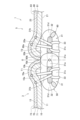
- FIG. 2 is a sectional view of a main part of the slide fastener shown in FIG. 1, showing a state in which first and second element rows are engaged.
- FIG. 2 is a cross-sectional view of a main part of the slide fastener shown in FIG. 1, showing a state in which first and second element rows are separated.
- FIG. 7 is a cross-sectional view of a main part of the slide fastener according to a modification of the first embodiment, and is a diagram showing a state in which the first and second element rows are engaged.
- the slide fastener based on each embodiment of this invention is demonstrated in detail based on drawing.
- the "vertical direction” of the slide fastener refers to the sliding direction of the slider, and refers to the longitudinal direction of the slide fastener, especially the direction in which the slider slides so as to engage the left and right element rows. is defined as “upward”, and the direction in which the left and right element rows are slid to separate them is defined as “downward”.
- the "left-right direction” is a direction in which a pair of element rows are arranged, a direction perpendicular to the sliding direction of the slider, and can also be referred to as the width direction of the slide fastener.
- the "front and back direction” is a direction perpendicular to the up-down direction and the left-right direction, and can also be translated as the thickness direction of the fastener tape or the height direction of the element row.
- the slide fastener 1 of this embodiment includes a pair of left and right fastener stringers 3 and 5, and a slider 40 that can open and close the pair of left and right fastener stringers 3 and 5. .
- the first and second fastener tapes 10 and 20 are woven or knitted fabrics made of polyester yarn or the like, and have excellent flexibility. Note that the first and second fastener tapes 10 and 20 may be made of nonwoven fabric.
- the first and second element rows 50 and 60 are coil-shaped fastener element rows formed by winding a synthetic resin monofilament in a certain direction, and have a plurality of elements 31.
- the first and second element rows 50 and 60 are formed by inserting a core string 32 into the inside of the plurality of elements 31 and sewing threads 33 that are double chain stitched to form the back surface of the first end 10a in the width direction of the first zipper tape 10. 11 and the back surface 21 of the widthwise one end 20a of the second fastener tape 20.
- the synthetic resin material for the monofilament include polyester and nylon.
- the element 31 includes a mating head 31a that meshes with and separates from the mating element 31, and a mesh head 31a that extends from the front end of the mating head 31a to the other end in the width direction and contacts the first and second fastener tapes 10 and 20.
- one end 10a of the first fastener tape 10 in the width direction and one end 20a of the second fastener tape 20 in the width direction are mutually connected. They are spaced apart in the width direction.
- one end 10a of the first fastener tape 10 in the width direction and one end 20a of the second fastener tape 20 in the width direction are shown in a state where the first and second element rows 50, 60 are separated.
- the shape is buckled like a mountain, but this is due to the habit of buckling when the first and second element rows 50 and 60 are meshed and separated after a certain period of time. It shows that there remains. After a certain period of time has passed with the first and second element rows 50 and 60 separated, the buckling habit is eliminated, and one widthwise end 10a of the first fastener tape 10 and one widthwise end of the second fastener tape 20 20a may each have a substantially planar shape as shown in FIG.
- one widthwise end 10a of the first fastener tape 10 engages the first and second element rows 50 and 60. It extends to the second fastener tape 20 side (one end side in the width direction) from the position O1 which is the center O, and the one end 20a in the width direction of the second fastener tape 20 is further away from the position O2 which is the engagement center O. 1 extends toward the fastener tape 10 side (one end side in the width direction). That is, the design is such that the first and second fastener tapes 10 and 20 overlap with the meshing center O when the first and second element rows 50 and 60 are meshed as shown in FIG.
- first and second fastener tapes 10 and 20 and the first and second element rows 50 and 60 are arranged in this way, when the first and second element rows 50 and 60 are engaged with each other as described later, In addition, the first and second fastener tapes 10 and 20 can be buckled in a mountainous manner and brought into close contact with each other.
- one end surface 10b in the width direction of the first fastener tape 10 is closer to the second fastener tape than the position O1 which is the engagement center O. 20 side (one end side in the width direction), and one end surface 20b in the width direction of the second fastener tape 20 is arranged on the first fastener tape 10 side (one end side in the width direction) than the position O2 which is the engagement center O. .
- the one end surface 10b in the width direction of the first fastener tape 10 may be arranged at a position overlapping at least a part of the engaging head 31a of the element 31 in the width direction, and the one end surface 31e in the width direction of the engaging head 31a in the width direction. (that is, one end surface in the width direction of the first element row 50) may be arranged on the same plane S1, or may be arranged closer to the second fastener tape 20 than the engaging head 31a.
- one end surface 10b in the width direction of the first fastener tape 10 is arranged on the same plane S1 as one end surface in the width direction of the first element row 50 in the width direction.
- One end surface 20b in the width direction of the second fastener tape 20 may be arranged at a position overlapping at least a portion of the engaging head 31a of the element 31 in the width direction, and one end surface 31f in the width direction of the engaging head 31a in the width direction. (that is, one end surface in the width direction of the second element row 60) may be arranged on the same plane S2, or may be arranged closer to the first fastener tape 10 than the engaging head 31a. In the example of FIG. 2, one end surface 20b in the width direction of the second fastener tape 20 is arranged on the same plane S2 as one end surface in the width direction of the second element row 60 in the width direction.
- a water repellent agent may be attached to the first and second fastener tapes 10 and 20. By attaching a water repellent agent, water repellency can be imparted to the slide fastener 1.
- water repellents include fluorine compounds, silicone compounds, acrylic water repellents, silicone composite water repellents, paraffin compounds, ethylene urea compounds, zirconium compounds, fatty acid amide compounds, and methylolamide.
- a water repellent such as a type compound, an alkyl urea type, or a fatty acid amide type can be used.
- any process can be applied to the process of attaching the water repellent to the first and second fastener tapes 10 and 20, but for example, the process of attaching the water repellent to the first and second fastener tapes 10 and 20 can be performed by winding the water repellent along the circumferential surface of a guide roller (not shown) to attach the fastener stringers 3 and 5.
- the water repellent may be immersed by guiding and continuously passing it through a container filled with the water repellent. In this process, the water repellent agent is efficiently applied to the entire surfaces of the first and second fastener tapes 10 and 20, the first and second element rows 50 and 60, the core cord 32, and the sewing thread 33 that constitute the fastener stringers 3 and 5. Granted.
- the water repellent applied to the entire surface of the fastener stringers 3, 5 is first dried by pulling the fastener stringers 3, 5 out of the container and passing them continuously through a drying chamber. Thereafter, the fastener stringers 3 and 5, on which the water repellent has been dried, are further continuously passed through a heat treatment chamber, thereby subjecting the dried water repellent to heat treatment.
- This heat treatment causes fusion and adhesion between all base materials of the first and second fastener tapes 10, 20, first and second element rows 50, 60, core string 32, and sewing thread 33 and the water repellent agent. It will be done.
- the slide fastener 1 can be used as a water-repellent fastener.
- the first and second fastener tapes 10 and 20 buckle in a mountain shape and come into close contact with each other.
- a gap inner partition is not formed between the two fastener tapes 10 and 20, and liquid is prevented from entering from the inner partition as in the prior art.
- one end surface 10b in the width direction and one end surface 20b in the width direction of the first and second fastener tapes 10 and 20 are , facing the element 31 side (back side) and abuts on the first and second element rows 50 and 60. Further, the surface 13 of the first end 10a in the width direction of the first fastener tape 10 and the surface 23 of the end 20a in the width direction of the second fastener tape 20 are in close contact with each other on the meshing center O.
- one end surface 10b and 20b in the width direction of the first and second fastener tapes 10 and 20 faces the front side, and one end surface 10a and 20a in the width direction which is the tape edge Since the surface becomes convex toward the surface, the texture of the surface deteriorates.
- first and second element rows 50 and 60 when the first and second element rows 50 and 60 are engaged with each other, one end surface 10b in the width direction and one end surface 20b in the width direction of the first and second fastener tapes 10 and 20 are
- the back surfaces 11 and 21 and the first and second element rows 50 and 60 (element 31) are spaced apart from each other in the front and back direction, and first and second spaces T1 and T2 are defined between them, respectively.
- the first and second fastener tapes 10 and 20 can be easily attached. Can be buckled. Moreover, the larger the first and second spaces T1 and T2, the larger the crimping area between the surfaces 13 and 23 of the one widthwise end 10a and the widthwise one end 20a of the first and second fastener tapes 10 and 20, The generation of gaps (partitions) between the first and second fastener tapes 10 and 20 is suppressed, contributing to improved appearance and improved water repellency and water resistance. Furthermore, the crimping between the first and second fastener tapes 10 and 20 is less likely to break down, and the shape is easily maintained.
- the first and second fastener tapes 10 and 20 are made of woven or knitted fabrics and have excellent flexibility, so when the first and second element rows 50 and 60 are interlocked with each other, the first and second fastener tapes 10 and 20 are The adhesion between the second fastener tapes 10 and 20 can be improved. Moreover, the buckled state of the first and second fastener tapes 10 and 20 can be maintained. Therefore, generation of a gap (partition portion) between the first and second fastener tapes 10 and 20 is suppressed, contributing to improved appearance and improved water repellency and water resistance. In addition, if the first and second fastener tapes 10 and 20 were molded from resin or the like, it would be difficult to form and maintain a buckled shape.
- FIG. 4 is a sectional view of a main part of a slide fastener according to a modification of the first embodiment, showing a state in which the first and second element rows are engaged.
- FIG. 3 compared to the example of FIG.
- the crimping area between the surface 13 of the one end 10a of the fastener tape 10 in the width direction and the surface 23 of the one end 20a of the second fastener tape 20 in the width direction is increased. In this way, by appropriately adjusting the crimping area, it is possible to meet the requirements for water repellency and water resistance.
- the slide fastener 1 of the second embodiment includes a first water stop film 70 (first water stop layer) provided on the surface 13 of the first fastener tape 10, and a second fastener tape 70 (first water stop layer) provided on the surface 13 of the first fastener tape 10.
- the tape 20 further includes a second water stop film 80 (second water stop layer) provided on the surface 23 of the tape 20. Therefore, the slide fastener 1 of this embodiment is a water-stop fastener having water-stop properties.
- the first and second water stop films 70 are made of thermosetting polyurethane film or the like on the surfaces 13 and 23 of the first and second fastener tapes 10 and 20 to which the first and second element rows 50 and 60 are sewn. It is formed by joining and integrating the water stop layer by adhesion, welding, etc.
- the slide fastener 1 is in a state in which a common water stop layer (first and second water stop films 70, 80) is integrally joined to the first and second fastener tapes 10, 20.
- a water repellent agent is applied to the slide fastener 1 using a method similar to that described above in the first embodiment.
- the fastener stringers 3 and 5 may be immersed in the water repellent by winding them around the circumferential surface of a guide roller (not shown) to guide them and continuously passing them through a container filled with the water repellent.
- the water repellent applied to the entire surface of the fastener stringers 3, 5 is first dried by pulling the fastener stringers 3, 5 out of the container and passing them continuously through a drying chamber. Thereafter, the fastener stringers 3 and 5, on which the water repellent has been dried, are further continuously passed through a heat treatment chamber, thereby subjecting the dried water repellent to heat treatment.
- the first and second fastener tapes 10, 20, the first and second element rows 50, 60, the core cord 32, the sewing thread 33, and the water-stop layer (the first and second water-stop films 70, 80) are Fusion and adhesion treatment is performed between all base materials and the water repellent.
- the heat-treated slide fastener 1 is taken out, and the single water-stop layer (first and second water-stop films 70, 80) connecting the left and right pair of fastener stringers 3, 5 is cut using a cutter.
- the first and second element rows 50 and 60 are cut in the length direction along the meshing portion where they mesh with each other, and are divided into left and right halves. In this way, a pair of left and right first and second water stop films 70 and 80 are formed.
- one widthwise end portion 10a, 70a of the first fastener tape 10 and the first water stop film 70 is connected to the first and second element rows 50, 60.
- the one end portions 20a, 80a extend toward the first fastener tape 10 side (one end side in the width direction) from the position O2 where the engagement center O is. That is, when the first and second element rows 50 and 60 are engaged as shown in FIG.
- the first and second fastener tapes 10 and 20 overlap with the engagement center O, and the first and second water stop tapes
- the films 70 and 80 are designed to overlap with the meshing center O.
- one end surface 10b and 70b in the width direction of the first fastener tape 10 and the first water stop film 70 is aligned with the meshing center O.
- the position O2 is located closer to the second fastener tape 20 (on one end in the width direction) than the position O1, and the one end surface 20b, 80b in the width direction of the second fastener tape 20 and the second water stop film 80 is the center of engagement O. It is arranged on the first fastener tape 10 side (one end side in the width direction).
- One end surface 10b, 70b in the width direction of the first fastener tape 10 and the first water stop film 70 may be arranged at a position overlapping with at least a part of the engaging head 31a of the element 31 in the width direction, and It may be arranged on the same plane S1 as one end surface 31e in the width direction of the head 31a (that is, one end surface in the width direction of the first element row 50), and may be arranged closer to the second fastener tape 20 than the engaging head 31a. It's okay.
- one widthwise end surface 10b, 70b of the first fastener tape 10 and the first water stop film 70 is arranged on the same plane S1 as the widthwise one end surface of the first element row 50 in the width direction. There is.
- One end surface 20b, 80b in the width direction of the second fastener tape 20 and the second water stop film 80 may be arranged at a position overlapping with at least a part of the engaging head 31a of the element 31 in the width direction, and It may be arranged on the same plane S2 as one widthwise end surface 31f of the head 31a (that is, one widthwise end surface of the second element row 60), and may be arranged closer to the first fastener tape 10 than the engaging head 31a. It's okay.
- one end surface 20b in the width direction of the second fastener tape 20 is disposed on the same plane S2 as one end surface in the width direction of the second element row 60 in the width direction.
- one end surface in the width direction 10b, 70b of the first fastener tape 10 and the first water stop film 70 and one end surface in the width direction of the first element row 50 are arranged on the same plane S1, and the second fastener tape 20
- the first and second element rows 50, 60 are meshed.
- one end surface 10b in the width direction and one end surface 20b in the width direction of the first and second fastener tapes 10 and 20 One end surface 70b in the width direction and one end surface 80b in the width direction of the first and second water stop films 70, 80 face the element 31 side (back side).
- One end surface 70b in the width direction and one end surface 80b in the width direction of the first and second water stop films 70 and 80 may come into contact with the first and second element rows 50 and 60.
- FIG. 7 is a cross-sectional view of a main part of a slide fastener according to a modification of the second embodiment, showing a state in which the first and second element rows are engaged.
- Crimp area is increasing. In this way, by appropriately adjusting the crimped area, it is possible to meet the requirements for water-stopping properties and water resistance.
- the first and second fastener tapes (20) are woven or knitted fabrics, The slide fastener (1) according to any one of [1] to [3].
- One end (10a) in the width direction of the first fastener tape extends closer to the second fastener tape (20) than the meshing center (O) of the first and second element rows (50, 60).
- one end (20a) in the width direction of the second fastener tape (20) extends closer to the first fastener tape (10) than the engagement center (O), so that the first and second fastener tapes
- one end (10a) in the width direction of the first fastener tape (10) and one end (20a) in the width direction of the second fastener tape (20) buckle like a mountain and stick to each other,
- the slide fastener (1) according to any one of [1] to [4].
- the first and second element rows (50, 60) are When meshed with each other, the first and second fastener tapes (20) can be buckled in a mountainous manner and brought into close contact with each other.
- the slide fastener (1) according to any one of [1] to [6], comprising:
Abstract
Une fermeture à glissière (1) comprend une paire de première et seconde bandes (10, 20), une première rangée d'éléments (50) et une seconde rangée d'éléments (60). Lorsque les première et seconde rangées d'éléments (50, 60) sont en prise l'une avec l'autre, une extrémité dans le sens de la largeur (10a) de la première bande de fermeture (10) et une extrémité dans le sens de la largeur (20a) de la seconde bande de fermeture (20) se déforme chacune en formes de pic et viennent en contact étroit l'une avec l'autre.
Priority Applications (4)
| Application Number | Priority Date | Filing Date | Title |
|---|---|---|---|
| PCT/JP2022/024334 WO2023243081A1 (fr) | 2022-06-17 | 2022-06-17 | Fermeture à glissière |
| CN202211303821.3A CN117281333A (zh) | 2022-06-17 | 2022-10-24 | 拉链 |
| CN202222801045.1U CN218942437U (zh) | 2022-06-17 | 2022-10-24 | 拉链 |
| TW111142384A TWI839938B (zh) | 2022-06-17 | 2022-11-07 | 拉鍊 |
Applications Claiming Priority (1)
| Application Number | Priority Date | Filing Date | Title |
|---|---|---|---|
| PCT/JP2022/024334 WO2023243081A1 (fr) | 2022-06-17 | 2022-06-17 | Fermeture à glissière |
Publications (1)
| Publication Number | Publication Date |
|---|---|
| WO2023243081A1 true WO2023243081A1 (fr) | 2023-12-21 |
Family
ID=86105382
Family Applications (1)
| Application Number | Title | Priority Date | Filing Date |
|---|---|---|---|
| PCT/JP2022/024334 WO2023243081A1 (fr) | 2022-06-17 | 2022-06-17 | Fermeture à glissière |
Country Status (2)
| Country | Link |
|---|---|
| CN (2) | CN218942437U (fr) |
| WO (1) | WO2023243081A1 (fr) |
Citations (3)
| Publication number | Priority date | Publication date | Assignee | Title |
|---|---|---|---|---|
| JP2000354505A (ja) * | 1999-05-28 | 2000-12-26 | Ykk Corp | 水密ジッパー |
| JP2014533572A (ja) * | 2011-11-22 | 2014-12-15 | Ykk株式会社 | スライドファスナー |
| CN109330117A (zh) * | 2018-09-28 | 2019-02-15 | 东莞市鼎富拉链科技有限公司 | 一种防水拉链 |
-
2022
- 2022-06-17 WO PCT/JP2022/024334 patent/WO2023243081A1/fr unknown
- 2022-10-24 CN CN202222801045.1U patent/CN218942437U/zh active Active
- 2022-10-24 CN CN202211303821.3A patent/CN117281333A/zh active Pending
Patent Citations (3)
| Publication number | Priority date | Publication date | Assignee | Title |
|---|---|---|---|---|
| JP2000354505A (ja) * | 1999-05-28 | 2000-12-26 | Ykk Corp | 水密ジッパー |
| JP2014533572A (ja) * | 2011-11-22 | 2014-12-15 | Ykk株式会社 | スライドファスナー |
| CN109330117A (zh) * | 2018-09-28 | 2019-02-15 | 东莞市鼎富拉链科技有限公司 | 一种防水拉链 |
Also Published As
| Publication number | Publication date |
|---|---|
| TW202400040A (zh) | 2024-01-01 |
| CN218942437U (zh) | 2023-05-02 |
| CN117281333A (zh) | 2023-12-26 |
Similar Documents
| Publication | Publication Date | Title |
|---|---|---|
| TWI627921B (zh) | Zipper-attached article and method of manufacturing the same with zipper | |
| KR101274938B1 (ko) | 은폐형 슬라이드 파스너용 파스너 스트링거 | |
| US8739372B2 (en) | Fastener stringer for hidden slide fastener | |
| TWI471102B (zh) | A sewing method for a zipper chain and a method of manufacturing the zipper attached product, and a zipper attached product | |
| US7520304B2 (en) | Fastener stringer of concealed type slide fastener | |
| CN107198301B (zh) | 附有拉链的物品及附有拉链的物品的制造方法 | |
| TWI397386B (zh) | A method of manufacturing a zipper chain and a method of manufacturing a zipper attached product, a zipper attached product, and a presser foot | |
| CN110169624B (zh) | 拉链牙链带、拉链及拉链牙链带安装构造 | |
| TWI574646B (zh) | Chains, zippers and items with zippers | |
| KR20070011123A (ko) | 슬라이드 파스너 | |
| WO2012070116A1 (fr) | Demi-chaîne de fermeture et fermeture à glissière | |
| WO2023243081A1 (fr) | Fermeture à glissière | |
| CN110545689B (zh) | 带拉链的产品及带拉链的产品的制造方法 | |
| TWI839938B (zh) | 拉鍊 | |
| WO2011111154A1 (fr) | Chaîne d'attaches, procédé permettant de coudre des rangées d'éléments, et procédé permettant de fabriquer des dispositifs d'enfilage d'attaches | |
| JP5269103B2 (ja) | 隠しスライドファスナー | |
| TW201609015A (zh) | 無拉鏈鏈布之鏈帶、無拉鏈鏈布之拉鏈及附有拉鏈之物品 | |
| JP2008154615A (ja) | スライドファスナー用ストリンガー | |
| CN219894874U (zh) | 一种拉链用布带及拉链 | |
| KR101540548B1 (ko) | 직입 파스너 스트링거 및 슬라이드 파스너 | |
| WO2023058095A1 (fr) | Chaîne de fermeture | |
| WO2020213134A1 (fr) | Élément d'arrêt, produit à fermeture à glissière et fermeture à glissière | |
| KR20090011598U (ko) | 고장력 슬라이드 파스너 |
Legal Events
| Date | Code | Title | Description |
|---|---|---|---|
| 121 | Ep: the epo has been informed by wipo that ep was designated in this application |
Ref document number: 22946897 Country of ref document: EP Kind code of ref document: A1 |