WO2023243081A1 - Slide fastener - Google Patents
Slide fastener Download PDFInfo
- Publication number
- WO2023243081A1 WO2023243081A1 PCT/JP2022/024334 JP2022024334W WO2023243081A1 WO 2023243081 A1 WO2023243081 A1 WO 2023243081A1 JP 2022024334 W JP2022024334 W JP 2022024334W WO 2023243081 A1 WO2023243081 A1 WO 2023243081A1
- Authority
- WO
- WIPO (PCT)
- Prior art keywords
- fastener
- width direction
- fastener tape
- water
- element rows
- Prior art date
Links
- XLYOFNOQVPJJNP-UHFFFAOYSA-N water Substances O XLYOFNOQVPJJNP-UHFFFAOYSA-N 0.000 claims description 93
- 239000005871 repellent Substances 0.000 description 26
- 230000002940 repellent Effects 0.000 description 24
- 238000005192 partition Methods 0.000 description 14
- 238000002788 crimping Methods 0.000 description 8
- 238000009958 sewing Methods 0.000 description 8
- 239000003795 chemical substances by application Substances 0.000 description 6
- 238000010438 heat treatment Methods 0.000 description 6
- 238000000034 method Methods 0.000 description 6
- 150000001875 compounds Chemical class 0.000 description 4
- 239000004744 fabric Substances 0.000 description 4
- 239000007788 liquid Substances 0.000 description 4
- 230000004048 modification Effects 0.000 description 4
- 238000012986 modification Methods 0.000 description 4
- 238000010586 diagram Methods 0.000 description 3
- 239000000463 material Substances 0.000 description 3
- 230000013011 mating Effects 0.000 description 3
- 238000004804 winding Methods 0.000 description 3
- 235000014113 dietary fatty acids Nutrition 0.000 description 2
- 238000001035 drying Methods 0.000 description 2
- 230000000694 effects Effects 0.000 description 2
- 229930195729 fatty acid Natural products 0.000 description 2
- 239000000194 fatty acid Substances 0.000 description 2
- 150000004665 fatty acids Chemical class 0.000 description 2
- 230000004927 fusion Effects 0.000 description 2
- 229920000728 polyester Polymers 0.000 description 2
- 229920001296 polysiloxane Chemical class 0.000 description 2
- 229920003002 synthetic resin Polymers 0.000 description 2
- 239000000057 synthetic resin Substances 0.000 description 2
- 239000004677 Nylon Substances 0.000 description 1
- NIXOWILDQLNWCW-UHFFFAOYSA-N acrylic acid group Chemical group C(C=C)(=O)O NIXOWILDQLNWCW-UHFFFAOYSA-N 0.000 description 1
- -1 alkyl urea Chemical compound 0.000 description 1
- 238000005452 bending Methods 0.000 description 1
- 239000004202 carbamide Substances 0.000 description 1
- 239000002131 composite material Substances 0.000 description 1
- 238000005520 cutting process Methods 0.000 description 1
- MGPYDQFQAJEDIG-UHFFFAOYSA-N ethene;urea Chemical class C=C.NC(N)=O MGPYDQFQAJEDIG-UHFFFAOYSA-N 0.000 description 1
- 150000002222 fluorine compounds Chemical class 0.000 description 1
- 230000002452 interceptive effect Effects 0.000 description 1
- 238000005304 joining Methods 0.000 description 1
- XMYQHJDBLRZMLW-UHFFFAOYSA-N methanolamine Chemical compound NCO XMYQHJDBLRZMLW-UHFFFAOYSA-N 0.000 description 1
- 239000004745 nonwoven fabric Substances 0.000 description 1
- 229920001778 nylon Polymers 0.000 description 1
- 239000012188 paraffin wax Substances 0.000 description 1
- 229920006264 polyurethane film Polymers 0.000 description 1
- 229920005989 resin Polymers 0.000 description 1
- 239000011347 resin Substances 0.000 description 1
- 229920001187 thermosetting polymer Polymers 0.000 description 1
- 238000003466 welding Methods 0.000 description 1
- 150000003755 zirconium compounds Chemical class 0.000 description 1
Images


Classifications
-
- A—HUMAN NECESSITIES
- A44—HABERDASHERY; JEWELLERY
- A44B—BUTTONS, PINS, BUCKLES, SLIDE FASTENERS, OR THE LIKE
- A44B19/00—Slide fasteners
- A44B19/02—Slide fasteners with a series of separate interlocking members secured to each stringer tape
- A44B19/04—Stringers arranged edge-to-edge when fastened, e.g. abutting stringers
-
- A—HUMAN NECESSITIES
- A44—HABERDASHERY; JEWELLERY
- A44B—BUTTONS, PINS, BUCKLES, SLIDE FASTENERS, OR THE LIKE
- A44B19/00—Slide fasteners
- A44B19/02—Slide fasteners with a series of separate interlocking members secured to each stringer tape
- A44B19/08—Stringers arranged side-by-side when fastened, e.g. at least partially superposed stringers
-
- A—HUMAN NECESSITIES
- A44—HABERDASHERY; JEWELLERY
- A44B—BUTTONS, PINS, BUCKLES, SLIDE FASTENERS, OR THE LIKE
- A44B19/00—Slide fasteners
- A44B19/24—Details
- A44B19/32—Means for making slide fasteners gas or watertight
Definitions
- the present invention relates to a slide fastener.
- slide fasteners there are two types of slide fasteners: regular slide fasteners, in which the element rows are mounted so that they can be seen on the outside (front side) of the product, and slide fasteners in which the element rows are mounted on the inside (back side) of the product, making them difficult to see.
- regular slide fasteners in which the element rows are mounted so that they can be seen on the outside (front side) of the product
- slide fasteners in which the element rows are mounted on the inside (back side) of the product, making them difficult to see.
- the side edges of the left and right fastener tapes are folded back into a U-shape in the width direction, and element rows are attached to the folded tape portions.
- Hidden type slide fasteners as-called hidden slide fasteners
- Backed slide fasteners have the advantage of not interfering with the design of the product due to their concealability, and are suitable for use in various products such as clothing, shoes, bags, and furniture. It is also used in seat covers for various types of seats.
- An example of such a reverse slide fastener is disclosed in Japanese Patent Laid-Open No. 2009-56076 (Patent Document 1).
- FIG. 8 is a sectional view showing the reverse slide fastener of Patent Document 1.
- the back-use slide fastener 100 disclosed in Patent Document 1 includes a pair of left and right fastener stringers 102, 102, a slider 101 that can open and close the pair of left and right fastener stringers 102, 102, have.
- the slider 101 has a slider body 110 and a handle 120.
- the slider fuselage 110 includes an upper wing plate 111, a lower wing plate 112 arranged parallel to and spaced from the upper wing plate 111, and a guide column (see FIG. 8) that connects the front ends of these upper and lower wing plates 111, 112. (not shown), a gate-shaped handle attachment column 114 integrally formed on the surface (upper surface) of the upper wing plate 111, and a handle mounting column 114 extending from the left and right edges of the rear side of the lower wing plate 112 toward the upper wing plate 111.
- the left and right flanges 115 are provided.
- the left and right pair of fastener stringers 102, 102 are made by inserting a core string 106 through a coiled element row 103, and sewing it to the opposing tape side edges of the left and right pair of fastener tapes 104, 104 with a sewing thread 105. It is formed by
- a gap is formed between a pair of left and right fastener tapes.
- a gap S is formed between the pair of left and right fastener tapes 104, 104.
- the present invention has been made in view of the above-mentioned problems, and its purpose is to provide a slide fastener that has excellent concealment of element rows and, in turn, excellent appearance.
- the slide fastener according to any one of [1] to [3]. [5] One end in the width direction of the first fastener tape extends closer to the second fastener tape than the engagement center of the first and second element rows, and one end in the width direction of the second fastener tape extends closer to the first fastener tape than the meshing center, so that when the first and second element rows are meshed with each other, one widthwise end of the first fastener tape and the second fastener One end of the tape in the width direction buckles in a mountain shape and comes into close contact with each other.
- the slide fastener according to any one of [1] to [4].
- the slide fastener according to any one of [1] to [6], comprising: [8] When the first and second element rows are engaged with each other, one end in the width direction of the first water stop layer and one end in the width direction of the second water stop layer sit in a mountain shape. bending and clinging to each other, The slide fastener according to [7]. [9]
- the first and second water-stopping layers each have a first water-stopping main surface in contact with the second main surface of the first and second fastener tapes, and a side opposite to the first water-stopping main surface.
- the slide fastener of the present invention when the first and second element rows are engaged with each other, one end in the width direction of the first fastener tape and one end in the width direction of the second fastener tape sit in a mountain shape. Bend over and cling to each other. Therefore, there is no gap (partition) between the first and second fastener tapes, and the element rows are better concealed, resulting in better appearance.
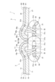
- FIG. 2 is a sectional view of a main part of the slide fastener shown in FIG. 1, showing a state in which first and second element rows are engaged.
- FIG. 2 is a cross-sectional view of a main part of the slide fastener shown in FIG. 1, showing a state in which first and second element rows are separated.
- FIG. 7 is a cross-sectional view of a main part of the slide fastener according to a modification of the first embodiment, and is a diagram showing a state in which the first and second element rows are engaged.
- the slide fastener based on each embodiment of this invention is demonstrated in detail based on drawing.
- the "vertical direction” of the slide fastener refers to the sliding direction of the slider, and refers to the longitudinal direction of the slide fastener, especially the direction in which the slider slides so as to engage the left and right element rows. is defined as “upward”, and the direction in which the left and right element rows are slid to separate them is defined as “downward”.
- the "left-right direction” is a direction in which a pair of element rows are arranged, a direction perpendicular to the sliding direction of the slider, and can also be referred to as the width direction of the slide fastener.
- the "front and back direction” is a direction perpendicular to the up-down direction and the left-right direction, and can also be translated as the thickness direction of the fastener tape or the height direction of the element row.
- the slide fastener 1 of this embodiment includes a pair of left and right fastener stringers 3 and 5, and a slider 40 that can open and close the pair of left and right fastener stringers 3 and 5. .
- the first and second fastener tapes 10 and 20 are woven or knitted fabrics made of polyester yarn or the like, and have excellent flexibility. Note that the first and second fastener tapes 10 and 20 may be made of nonwoven fabric.
- the first and second element rows 50 and 60 are coil-shaped fastener element rows formed by winding a synthetic resin monofilament in a certain direction, and have a plurality of elements 31.
- the first and second element rows 50 and 60 are formed by inserting a core string 32 into the inside of the plurality of elements 31 and sewing threads 33 that are double chain stitched to form the back surface of the first end 10a in the width direction of the first zipper tape 10. 11 and the back surface 21 of the widthwise one end 20a of the second fastener tape 20.
- the synthetic resin material for the monofilament include polyester and nylon.
- the element 31 includes a mating head 31a that meshes with and separates from the mating element 31, and a mesh head 31a that extends from the front end of the mating head 31a to the other end in the width direction and contacts the first and second fastener tapes 10 and 20.
- one end 10a of the first fastener tape 10 in the width direction and one end 20a of the second fastener tape 20 in the width direction are mutually connected. They are spaced apart in the width direction.
- one end 10a of the first fastener tape 10 in the width direction and one end 20a of the second fastener tape 20 in the width direction are shown in a state where the first and second element rows 50, 60 are separated.
- the shape is buckled like a mountain, but this is due to the habit of buckling when the first and second element rows 50 and 60 are meshed and separated after a certain period of time. It shows that there remains. After a certain period of time has passed with the first and second element rows 50 and 60 separated, the buckling habit is eliminated, and one widthwise end 10a of the first fastener tape 10 and one widthwise end of the second fastener tape 20 20a may each have a substantially planar shape as shown in FIG.
- one widthwise end 10a of the first fastener tape 10 engages the first and second element rows 50 and 60. It extends to the second fastener tape 20 side (one end side in the width direction) from the position O1 which is the center O, and the one end 20a in the width direction of the second fastener tape 20 is further away from the position O2 which is the engagement center O. 1 extends toward the fastener tape 10 side (one end side in the width direction). That is, the design is such that the first and second fastener tapes 10 and 20 overlap with the meshing center O when the first and second element rows 50 and 60 are meshed as shown in FIG.
- first and second fastener tapes 10 and 20 and the first and second element rows 50 and 60 are arranged in this way, when the first and second element rows 50 and 60 are engaged with each other as described later, In addition, the first and second fastener tapes 10 and 20 can be buckled in a mountainous manner and brought into close contact with each other.
- one end surface 10b in the width direction of the first fastener tape 10 is closer to the second fastener tape than the position O1 which is the engagement center O. 20 side (one end side in the width direction), and one end surface 20b in the width direction of the second fastener tape 20 is arranged on the first fastener tape 10 side (one end side in the width direction) than the position O2 which is the engagement center O. .
- the one end surface 10b in the width direction of the first fastener tape 10 may be arranged at a position overlapping at least a part of the engaging head 31a of the element 31 in the width direction, and the one end surface 31e in the width direction of the engaging head 31a in the width direction. (that is, one end surface in the width direction of the first element row 50) may be arranged on the same plane S1, or may be arranged closer to the second fastener tape 20 than the engaging head 31a.
- one end surface 10b in the width direction of the first fastener tape 10 is arranged on the same plane S1 as one end surface in the width direction of the first element row 50 in the width direction.
- One end surface 20b in the width direction of the second fastener tape 20 may be arranged at a position overlapping at least a portion of the engaging head 31a of the element 31 in the width direction, and one end surface 31f in the width direction of the engaging head 31a in the width direction. (that is, one end surface in the width direction of the second element row 60) may be arranged on the same plane S2, or may be arranged closer to the first fastener tape 10 than the engaging head 31a. In the example of FIG. 2, one end surface 20b in the width direction of the second fastener tape 20 is arranged on the same plane S2 as one end surface in the width direction of the second element row 60 in the width direction.
- a water repellent agent may be attached to the first and second fastener tapes 10 and 20. By attaching a water repellent agent, water repellency can be imparted to the slide fastener 1.
- water repellents include fluorine compounds, silicone compounds, acrylic water repellents, silicone composite water repellents, paraffin compounds, ethylene urea compounds, zirconium compounds, fatty acid amide compounds, and methylolamide.
- a water repellent such as a type compound, an alkyl urea type, or a fatty acid amide type can be used.
- any process can be applied to the process of attaching the water repellent to the first and second fastener tapes 10 and 20, but for example, the process of attaching the water repellent to the first and second fastener tapes 10 and 20 can be performed by winding the water repellent along the circumferential surface of a guide roller (not shown) to attach the fastener stringers 3 and 5.
- the water repellent may be immersed by guiding and continuously passing it through a container filled with the water repellent. In this process, the water repellent agent is efficiently applied to the entire surfaces of the first and second fastener tapes 10 and 20, the first and second element rows 50 and 60, the core cord 32, and the sewing thread 33 that constitute the fastener stringers 3 and 5. Granted.
- the water repellent applied to the entire surface of the fastener stringers 3, 5 is first dried by pulling the fastener stringers 3, 5 out of the container and passing them continuously through a drying chamber. Thereafter, the fastener stringers 3 and 5, on which the water repellent has been dried, are further continuously passed through a heat treatment chamber, thereby subjecting the dried water repellent to heat treatment.
- This heat treatment causes fusion and adhesion between all base materials of the first and second fastener tapes 10, 20, first and second element rows 50, 60, core string 32, and sewing thread 33 and the water repellent agent. It will be done.
- the slide fastener 1 can be used as a water-repellent fastener.
- the first and second fastener tapes 10 and 20 buckle in a mountain shape and come into close contact with each other.
- a gap inner partition is not formed between the two fastener tapes 10 and 20, and liquid is prevented from entering from the inner partition as in the prior art.
- one end surface 10b in the width direction and one end surface 20b in the width direction of the first and second fastener tapes 10 and 20 are , facing the element 31 side (back side) and abuts on the first and second element rows 50 and 60. Further, the surface 13 of the first end 10a in the width direction of the first fastener tape 10 and the surface 23 of the end 20a in the width direction of the second fastener tape 20 are in close contact with each other on the meshing center O.
- one end surface 10b and 20b in the width direction of the first and second fastener tapes 10 and 20 faces the front side, and one end surface 10a and 20a in the width direction which is the tape edge Since the surface becomes convex toward the surface, the texture of the surface deteriorates.
- first and second element rows 50 and 60 when the first and second element rows 50 and 60 are engaged with each other, one end surface 10b in the width direction and one end surface 20b in the width direction of the first and second fastener tapes 10 and 20 are
- the back surfaces 11 and 21 and the first and second element rows 50 and 60 (element 31) are spaced apart from each other in the front and back direction, and first and second spaces T1 and T2 are defined between them, respectively.
- the first and second fastener tapes 10 and 20 can be easily attached. Can be buckled. Moreover, the larger the first and second spaces T1 and T2, the larger the crimping area between the surfaces 13 and 23 of the one widthwise end 10a and the widthwise one end 20a of the first and second fastener tapes 10 and 20, The generation of gaps (partitions) between the first and second fastener tapes 10 and 20 is suppressed, contributing to improved appearance and improved water repellency and water resistance. Furthermore, the crimping between the first and second fastener tapes 10 and 20 is less likely to break down, and the shape is easily maintained.
- the first and second fastener tapes 10 and 20 are made of woven or knitted fabrics and have excellent flexibility, so when the first and second element rows 50 and 60 are interlocked with each other, the first and second fastener tapes 10 and 20 are The adhesion between the second fastener tapes 10 and 20 can be improved. Moreover, the buckled state of the first and second fastener tapes 10 and 20 can be maintained. Therefore, generation of a gap (partition portion) between the first and second fastener tapes 10 and 20 is suppressed, contributing to improved appearance and improved water repellency and water resistance. In addition, if the first and second fastener tapes 10 and 20 were molded from resin or the like, it would be difficult to form and maintain a buckled shape.
- FIG. 4 is a sectional view of a main part of a slide fastener according to a modification of the first embodiment, showing a state in which the first and second element rows are engaged.
- FIG. 3 compared to the example of FIG.
- the crimping area between the surface 13 of the one end 10a of the fastener tape 10 in the width direction and the surface 23 of the one end 20a of the second fastener tape 20 in the width direction is increased. In this way, by appropriately adjusting the crimping area, it is possible to meet the requirements for water repellency and water resistance.
- the slide fastener 1 of the second embodiment includes a first water stop film 70 (first water stop layer) provided on the surface 13 of the first fastener tape 10, and a second fastener tape 70 (first water stop layer) provided on the surface 13 of the first fastener tape 10.
- the tape 20 further includes a second water stop film 80 (second water stop layer) provided on the surface 23 of the tape 20. Therefore, the slide fastener 1 of this embodiment is a water-stop fastener having water-stop properties.
- the first and second water stop films 70 are made of thermosetting polyurethane film or the like on the surfaces 13 and 23 of the first and second fastener tapes 10 and 20 to which the first and second element rows 50 and 60 are sewn. It is formed by joining and integrating the water stop layer by adhesion, welding, etc.
- the slide fastener 1 is in a state in which a common water stop layer (first and second water stop films 70, 80) is integrally joined to the first and second fastener tapes 10, 20.
- a water repellent agent is applied to the slide fastener 1 using a method similar to that described above in the first embodiment.
- the fastener stringers 3 and 5 may be immersed in the water repellent by winding them around the circumferential surface of a guide roller (not shown) to guide them and continuously passing them through a container filled with the water repellent.
- the water repellent applied to the entire surface of the fastener stringers 3, 5 is first dried by pulling the fastener stringers 3, 5 out of the container and passing them continuously through a drying chamber. Thereafter, the fastener stringers 3 and 5, on which the water repellent has been dried, are further continuously passed through a heat treatment chamber, thereby subjecting the dried water repellent to heat treatment.
- the first and second fastener tapes 10, 20, the first and second element rows 50, 60, the core cord 32, the sewing thread 33, and the water-stop layer (the first and second water-stop films 70, 80) are Fusion and adhesion treatment is performed between all base materials and the water repellent.
- the heat-treated slide fastener 1 is taken out, and the single water-stop layer (first and second water-stop films 70, 80) connecting the left and right pair of fastener stringers 3, 5 is cut using a cutter.
- the first and second element rows 50 and 60 are cut in the length direction along the meshing portion where they mesh with each other, and are divided into left and right halves. In this way, a pair of left and right first and second water stop films 70 and 80 are formed.
- one widthwise end portion 10a, 70a of the first fastener tape 10 and the first water stop film 70 is connected to the first and second element rows 50, 60.
- the one end portions 20a, 80a extend toward the first fastener tape 10 side (one end side in the width direction) from the position O2 where the engagement center O is. That is, when the first and second element rows 50 and 60 are engaged as shown in FIG.
- the first and second fastener tapes 10 and 20 overlap with the engagement center O, and the first and second water stop tapes
- the films 70 and 80 are designed to overlap with the meshing center O.
- one end surface 10b and 70b in the width direction of the first fastener tape 10 and the first water stop film 70 is aligned with the meshing center O.
- the position O2 is located closer to the second fastener tape 20 (on one end in the width direction) than the position O1, and the one end surface 20b, 80b in the width direction of the second fastener tape 20 and the second water stop film 80 is the center of engagement O. It is arranged on the first fastener tape 10 side (one end side in the width direction).
- One end surface 10b, 70b in the width direction of the first fastener tape 10 and the first water stop film 70 may be arranged at a position overlapping with at least a part of the engaging head 31a of the element 31 in the width direction, and It may be arranged on the same plane S1 as one end surface 31e in the width direction of the head 31a (that is, one end surface in the width direction of the first element row 50), and may be arranged closer to the second fastener tape 20 than the engaging head 31a. It's okay.
- one widthwise end surface 10b, 70b of the first fastener tape 10 and the first water stop film 70 is arranged on the same plane S1 as the widthwise one end surface of the first element row 50 in the width direction. There is.
- One end surface 20b, 80b in the width direction of the second fastener tape 20 and the second water stop film 80 may be arranged at a position overlapping with at least a part of the engaging head 31a of the element 31 in the width direction, and It may be arranged on the same plane S2 as one widthwise end surface 31f of the head 31a (that is, one widthwise end surface of the second element row 60), and may be arranged closer to the first fastener tape 10 than the engaging head 31a. It's okay.
- one end surface 20b in the width direction of the second fastener tape 20 is disposed on the same plane S2 as one end surface in the width direction of the second element row 60 in the width direction.
- one end surface in the width direction 10b, 70b of the first fastener tape 10 and the first water stop film 70 and one end surface in the width direction of the first element row 50 are arranged on the same plane S1, and the second fastener tape 20
- the first and second element rows 50, 60 are meshed.
- one end surface 10b in the width direction and one end surface 20b in the width direction of the first and second fastener tapes 10 and 20 One end surface 70b in the width direction and one end surface 80b in the width direction of the first and second water stop films 70, 80 face the element 31 side (back side).
- One end surface 70b in the width direction and one end surface 80b in the width direction of the first and second water stop films 70 and 80 may come into contact with the first and second element rows 50 and 60.
- FIG. 7 is a cross-sectional view of a main part of a slide fastener according to a modification of the second embodiment, showing a state in which the first and second element rows are engaged.
- Crimp area is increasing. In this way, by appropriately adjusting the crimped area, it is possible to meet the requirements for water-stopping properties and water resistance.
- the first and second fastener tapes (20) are woven or knitted fabrics, The slide fastener (1) according to any one of [1] to [3].
- One end (10a) in the width direction of the first fastener tape extends closer to the second fastener tape (20) than the meshing center (O) of the first and second element rows (50, 60).
- one end (20a) in the width direction of the second fastener tape (20) extends closer to the first fastener tape (10) than the engagement center (O), so that the first and second fastener tapes
- one end (10a) in the width direction of the first fastener tape (10) and one end (20a) in the width direction of the second fastener tape (20) buckle like a mountain and stick to each other,
- the slide fastener (1) according to any one of [1] to [4].
- the first and second element rows (50, 60) are When meshed with each other, the first and second fastener tapes (20) can be buckled in a mountainous manner and brought into close contact with each other.
- the slide fastener (1) according to any one of [1] to [6], comprising:
Abstract
A slide fastener (1) includes a pair of first and second tapes (10, 20), a first element row (50), and a second element row (60). When the first and second element rows (50, 60) are engaged with each other, one widthwise end (10a) of the first fastener tape (10) and one widthwise end (20a) of the second fastener tape (20) each buckle into peaked forms and come into close contact with each other.
Description
本発明は、スライドファスナーに関する。
The present invention relates to a slide fastener.
スライドファスナーの種類としては、一般的に、エレメント列が製品の外側(表側)に見えるように取着される通常タイプのスライドファスナー、エレメント列が製品の内側(裏側)に取着されて見え難くなる裏使いタイプのスライドファスナー(所謂、裏使いスライドファスナー)、及び、左右のファスナーテープの側縁部がその幅方向に関してU字状に折り返されるとともにその折り返されたテープ部分にエレメント列が取着される隠しタイプのスライドファスナー(所謂、隠しスライドファスナー)等が知られている。
Generally speaking, there are two types of slide fasteners: regular slide fasteners, in which the element rows are mounted so that they can be seen on the outside (front side) of the product, and slide fasteners in which the element rows are mounted on the inside (back side) of the product, making them difficult to see. The side edges of the left and right fastener tapes are folded back into a U-shape in the width direction, and element rows are attached to the folded tape portions. Hidden type slide fasteners (so-called hidden slide fasteners) and the like are known.
裏使いスライドファスナーは、その隠蔽性から製品のデザイン性を妨げないという利点を生かして、各種衣類や靴、鞄、家具等の製品に好適に使用され、また近年では、自動車、列車、航空機等の各種シート用シートカバー等にも使用されている。このような裏使いスライドファスナーの一例が、特開2009-56076号公報(特許文献1)に開示されている。
Backed slide fasteners have the advantage of not interfering with the design of the product due to their concealability, and are suitable for use in various products such as clothing, shoes, bags, and furniture. It is also used in seat covers for various types of seats. An example of such a reverse slide fastener is disclosed in Japanese Patent Laid-Open No. 2009-56076 (Patent Document 1).
図8は、特許文献1の裏使いスライドファスナーを示す断面図である。図8に示すように、特許文献1に開示された裏使いスライドファスナー100は、左右一対のファスナーストリンガ102,102と、左右一対のファスナーストリンガ102,102を開閉することが可能なスライダー101と、を有している。
FIG. 8 is a sectional view showing the reverse slide fastener of Patent Document 1. As shown in FIG. 8, the back-use slide fastener 100 disclosed in Patent Document 1 includes a pair of left and right fastener stringers 102, 102, a slider 101 that can open and close the pair of left and right fastener stringers 102, 102, have.
スライダー101は、スライダー胴体110と、引手120と、を有している。スライダー胴体110は、上翼板111と、上翼板111と離間して平行に配された下翼板112と、これらの上下翼板111,112の前端部を連結する案内柱(図8には不図示)と、上翼板111の表面(上面)に一体形成された門型形状の引手取付柱114と、下翼板112の後部側の左右両側縁から上翼板111に向けて立設した左右のフランジ115と、を有している。
The slider 101 has a slider body 110 and a handle 120. The slider fuselage 110 includes an upper wing plate 111, a lower wing plate 112 arranged parallel to and spaced from the upper wing plate 111, and a guide column (see FIG. 8) that connects the front ends of these upper and lower wing plates 111, 112. (not shown), a gate-shaped handle attachment column 114 integrally formed on the surface (upper surface) of the upper wing plate 111, and a handle mounting column 114 extending from the left and right edges of the rear side of the lower wing plate 112 toward the upper wing plate 111. The left and right flanges 115 are provided.
左右一対のファスナーストリンガ102,102は、コイル状のエレメント列103に芯紐106を挿通したものを、左右一対のファスナーテープ104、104の相対するテープ側縁部に縫着糸105で縫着することによって形成されている。
The left and right pair of fastener stringers 102, 102 are made by inserting a core string 106 through a coiled element row 103, and sewing it to the opposing tape side edges of the left and right pair of fastener tapes 104, 104 with a sewing thread 105. It is formed by
通常、裏使いスライドファスナーには、左右一対のファスナーテープの間に隙間(所謂、中仕切部)が形成される。実際、図8に示した特許文献1の裏使いスライドファスナー100においても、左右一対のファスナーテープ104,104の間に隙間Sが形成される。
Normally, in reverse slide fasteners, a gap (so-called middle partition) is formed between a pair of left and right fastener tapes. In fact, also in the reverse slide fastener 100 of Patent Document 1 shown in FIG. 8, a gap S is formed between the pair of left and right fastener tapes 104, 104.
したがって、左右一対のファスナーテープ104,104に互いに離れる方向の外力(所謂、横引き)が作用した場合に、使用者が裏使いスライドファスナー100を表面側(図8の上側)から見た時、隙間Sを介してエレメント列103が視認され得る。このようなエレメント列103の隠蔽性の低下は、裏使いスライドファスナー100が用いられる物品、特にカーシート、鞄、家具等の美観が重視される物品、のデザイン性を悪化させる点で好ましくない。
Therefore, when an external force (so-called lateral pulling) is applied to the pair of left and right fastener tapes 104, 104 in the direction of separating them from each other, when the user views the back-use slide fastener 100 from the front side (upper side of FIG. 8), The element row 103 can be visually recognized through the gap S. Such a decrease in the concealability of the element array 103 is undesirable in that it deteriorates the design of articles in which the reverse slide fastener 100 is used, particularly articles for which aesthetics are important, such as car seats, bags, and furniture.
本発明は、以上のような問題点に鑑みてなされたものであり、その目的は、エレメント列の隠蔽性に優れ、ひいては外観に優れたスライドファスナーを提供することにある。
The present invention has been made in view of the above-mentioned problems, and its purpose is to provide a slide fastener that has excellent concealment of element rows and, in turn, excellent appearance.
上記課題を解決するため、本発明は以下の構成によって達成される。
[1] 長尺状であって、それぞれ第1主面と前記第1主面の反対側の第2主面とを有する、一対の第1及び第2ファスナーテープと、
前記第1ファスナーテープの幅方向一端部の前記第1主面に設けられた、第1エレメント列と、
前記第2ファスナーテープの幅方向一端部の前記第1主面に設けられた、第2エレメント列と、
を備えるスライドファスナーであって、
前記第1及び第2エレメント列を互いに噛み合わせた際に、前記第1ファスナーテープの幅方向一端部と、前記第2ファスナーテープの幅方向一端部と、がそれぞれ山なりに座屈して互いに密着する、
スライドファスナー。
[2] 前記第1及び第2エレメント列を互いに噛み合わせた際に、前記第1ファスナーテープの幅方向一端部の前記第2主面と、前記第2ファスナーテープの幅方向一端部の前記第2主面と、が互いに密着する、
[1]に記載のスライドファスナー。
[3] 前記第1及び第2エレメント列を互いに噛み合わせた際に、前記第1ファスナーテープの幅方向一端部の前記第1主面と前記第1エレメント列との間には第1空間が画成され、
前記第2ファスナーテープの幅方向一端部の前記第1主面と前記第2エレメント列との間には第2空間が画成される、
[1]又は[2]に記載のスライドファスナー。
[4] 前記第1及び第2ファスナーテープは、織物又は編物である、
[1]~[3]のいずれかに記載のスライドファスナー。
[5]前記第1ファスナーテープの幅方向一端部が前記第1及び第2エレメント列の噛合中心よりも前記第2ファスナーテープ側に延在し、且つ、前記第2ファスナーテープの幅方向一端部が前記噛合中心よりも前記第1ファスナーテープ側に延在することで、前記第1及び第2エレメント列を互いに噛み合わせた際に、前記第1ファスナーテープの幅方向一端部と前記第2ファスナーテープの幅方向一端部とが山なりに座屈して互いに密着する、
[1]~[4]のいずれかに記載のスライドファスナー。
[6] 前記第1ファスナーテープの幅方向一端面と前記第1エレメント列の幅方向一端面とは同一平面上に配置され、且つ、前記第2ファスナーテープの幅方向一端面と前記第2エレメント列の幅方向一端面とは同一平面上に配置されることで、前記第1及び第2エレメント列を互いに噛み合わせた際に、前記第1ファスナーテープの幅方向一端部と前記第2ファスナーテープの幅方向一端部とが山なりに座屈して互いに密着する、
[5]に記載のスライドファスナー。
[7] 前記第1ファスナーテープの前記第2主面に設けられた第1止水層と、
前記第2ファスナーテープの前記第2主面に設けられた第2止水層と、
を備える、[1]~[6]のいずれかに記載のスライドファスナー。
[8] 前記第1及び第2エレメント列を互いに噛み合わせた際に、前記第1止水層の幅方向一端部と、前記第2止水層の幅方向一端部と、が山なりに座屈して互いに密着する、
[7]に記載のスライドファスナー。
[9] 前記第1及び第2止水層はそれぞれ、前記第1及び第2ファスナーテープの前記第2主面,と接する第1止水主面と、前記第1止水主面の反対側の第2止水主面,と、を備え、
前記第1及び第2エレメント列を互いに噛み合わせた際に、前記第1止水層の幅方向一端部の前記第2止水主面と、前記第2止水層の幅方向一端部の前記第2止水主面と、が互いに密着する、
[8]に記載のスライドファスナー。 MEANS TO SOLVE THE PROBLEM In order to solve the said subject, this invention is achieved by the following structure.
[1] A pair of first and second fastener tapes that are elongated and each have a first main surface and a second main surface opposite to the first main surface;
a first element row provided on the first main surface at one end in the width direction of the first fastener tape;
a second element row provided on the first main surface at one end in the width direction of the second fastener tape;
A slide fastener comprising:
When the first and second element rows are engaged with each other, one end in the width direction of the first fastener tape and one end in the width direction of the second fastener tape buckle in a mountain shape and come into close contact with each other. do,
Slide fastener.
[2] When the first and second element rows are engaged with each other, the second main surface at one end in the width direction of the first fastener tape and the second main surface at one end in the width direction of the second fastener tape The two main surfaces are in close contact with each other,
The slide fastener according to [1].
[3] When the first and second element rows are engaged with each other, a first space is formed between the first main surface at one end in the width direction of the first fastener tape and the first element row. defined,
A second space is defined between the first main surface at one end in the width direction of the second fastener tape and the second element row.
The slide fastener according to [1] or [2].
[4] The first and second fastener tapes are woven or knitted.
The slide fastener according to any one of [1] to [3].
[5] One end in the width direction of the first fastener tape extends closer to the second fastener tape than the engagement center of the first and second element rows, and one end in the width direction of the second fastener tape extends closer to the first fastener tape than the meshing center, so that when the first and second element rows are meshed with each other, one widthwise end of the first fastener tape and the second fastener One end of the tape in the width direction buckles in a mountain shape and comes into close contact with each other.
The slide fastener according to any one of [1] to [4].
[6] One end surface in the width direction of the first fastener tape and one end surface in the width direction of the first element row are arranged on the same plane, and one end surface in the width direction of the second fastener tape and the second element By being arranged on the same plane as one end surface in the width direction of the row, when the first and second element rows are engaged with each other, one end in the width direction of the first fastener tape and the second fastener tape One end in the width direction is buckled in a mountain shape and comes into close contact with each other.
The slide fastener according to [5].
[7] a first water stop layer provided on the second main surface of the first fastener tape;
a second water stop layer provided on the second main surface of the second fastener tape;
The slide fastener according to any one of [1] to [6], comprising:
[8] When the first and second element rows are engaged with each other, one end in the width direction of the first water stop layer and one end in the width direction of the second water stop layer sit in a mountain shape. bending and clinging to each other,
The slide fastener according to [7].
[9] The first and second water-stopping layers each have a first water-stopping main surface in contact with the second main surface of the first and second fastener tapes, and a side opposite to the first water-stopping main surface. a second water-stop main surface, and
When the first and second element rows are engaged with each other, the second water-stop main surface at one end in the width direction of the first water-stop layer and the main surface at one end in the width direction of the second water-stop layer and the second water-stop main surface are in close contact with each other.
The slide fastener according to [8].
本発明のスライドファスナーによれば、第1及び第2エレメント列を互いに噛み合わせた際に、第1ファスナーテープの幅方向一端部と第2ファスナーテープの幅方向一端部とがそれぞれ山なりに座屈して互いに密着する。したがって、第1及び第2ファスナーテープの隙間(中仕切部)が無くなり、エレメント列の隠蔽性に優れ、ひいては外観に優れる。
According to the slide fastener of the present invention, when the first and second element rows are engaged with each other, one end in the width direction of the first fastener tape and one end in the width direction of the second fastener tape sit in a mountain shape. Bend over and cling to each other. Therefore, there is no gap (partition) between the first and second fastener tapes, and the element rows are better concealed, resulting in better appearance.
以下、本発明の各実施形態に係るスライドファスナーについて図面に基づいて詳細に説明する。
なお、本明細書中、スライドファスナーについて「上下方向」とは、スライダーの摺動方向であり、スライドファスナーの長手方向を言い、特に、スライダーが左右のエレメント列を噛合させるように摺動する方向を「上方」とし、左右のエレメント列を分離させるように摺動する方向を「下方」とする。
また、スライドファスナーについて「左右方向」とは、一対のエレメント列が並べられる方向で、スライダーの摺動方向に直交する方向であり、スライドファスナーの幅方向とも言い換えることもできる。
さらに、スライドファスナー及び上止について「表裏方向」とは、上下方向と左右方向に直交する方向であり、ファスナーテープの厚さ方向やエレメント列の高さ方向と言い換えることもできる。 EMBODIMENT OF THE INVENTION Hereinafter, the slide fastener based on each embodiment of this invention is demonstrated in detail based on drawing.
In this specification, the "vertical direction" of the slide fastener refers to the sliding direction of the slider, and refers to the longitudinal direction of the slide fastener, especially the direction in which the slider slides so as to engage the left and right element rows. is defined as "upward", and the direction in which the left and right element rows are slid to separate them is defined as "downward".
Further, regarding the slide fastener, the "left-right direction" is a direction in which a pair of element rows are arranged, a direction perpendicular to the sliding direction of the slider, and can also be referred to as the width direction of the slide fastener.
Furthermore, regarding the slide fastener and the top stop, the "front and back direction" is a direction perpendicular to the up-down direction and the left-right direction, and can also be translated as the thickness direction of the fastener tape or the height direction of the element row.
(第1実施形態)
図1は、本発明に係るスライドファスナーの第1実施形態の表面図である。図2は、図1に示すスライドファスナーの要部断面図であり、第1及び第2エレメント列を噛合した状態を示す図である。図3は、図1に示すスライドファスナーの要部断面図であり、第1及び第2エレメント列を分離した状態を示す図である。 (First embodiment)
FIG. 1 is a surface view of a first embodiment of the slide fastener according to the present invention. FIG. 2 is a sectional view of a main part of the slide fastener shown in FIG. 1, showing a state in which the first and second element rows are engaged. FIG. 3 is a sectional view of a main part of the slide fastener shown in FIG. 1, and is a diagram showing a state in which the first and second element rows are separated.
図1~図3に示すように、本実施形態のスライドファスナー1は、左右一対のファスナーストリンガ3,5と、左右一対のファスナーストリンガ3,5を開閉することが可能なスライダー40と、を備える。
As shown in FIGS. 1 to 3, the slide fastener 1 of this embodiment includes a pair of left and right fastener stringers 3 and 5, and a slider 40 that can open and close the pair of left and right fastener stringers 3 and 5. .
左右一対のファスナーストリンガ3,5は、長尺状であってそれぞれ裏面11,21(第1主面)と裏面11,21の反対側の表面13,23(第2主面)とを有する左右一対の第1及び第2ファスナーテープ10,20と、第1ファスナーテープ10の幅方向一端部10a(図2の右端部)の裏面11に設けられた第1エレメント列50と、第2ファスナーテープ20の幅方向一端部20a(図2の左端部)の裏面21に設けられた第2エレメント列60と、を備える。以降、第1ファスナーテープ10および第2ファスナーテープ20の幅方向のうち、エレメント列が設けられている側を幅方向一端側、そうでない側を幅方向他端側と定義する。
The left and right pair of fastener stringers 3, 5 are elongated, and each has a back surface 11, 21 (first main surface) and a surface 13, 23 (second main surface) opposite to the back surface 11, 21. A pair of first and second fastener tapes 10, 20, a first element row 50 provided on the back surface 11 of one widthwise end 10a (right end in FIG. 2) of the first fastener tape 10, and a second fastener tape A second element row 60 provided on the back surface 21 of one end 20a in the width direction (left end in FIG. 2) of 20. Hereinafter, in the width direction of the first fastener tape 10 and the second fastener tape 20, the side where the element rows are provided will be defined as one widthwise end side, and the other side will be defined as the other widthwise end side.
第1及び第2ファスナーテープ10,20は、ポリエステル糸等からなる織物又は編物であり、柔軟性に優れる。なお、第1及び第2ファスナーテープ10,20は、不織布であってもよい
The first and second fastener tapes 10 and 20 are woven or knitted fabrics made of polyester yarn or the like, and have excellent flexibility. Note that the first and second fastener tapes 10 and 20 may be made of nonwoven fabric.
スライダー40は、左右一対の第1及び第2エレメント列50,60を噛合及び分離させる。スライダー40は、胴体41と、胴体41の表面に設けられる引手取付部42と、引手取付部42に取り付けられる引手43と、を備える。そして、スライダー40を上方に移動することで、図2に示すように左右一対の第1及び第2エレメント列50,60が噛合し、スライダー40を下方に移動することで、図3に示すように左右一対の第1及び第2エレメント列50,60が分離する。なお、スライドファスナー1は、図示しない上止部や下止部を備えてもよい。また、下止部に代えて、箱棒及び箱体を有する開き具が設けられても良い。
The slider 40 engages and separates the pair of left and right first and second element rows 50 and 60. The slider 40 includes a body 41, a handle attachment part 42 provided on the surface of the body 41, and a handle 43 attached to the handle attachment part 42. By moving the slider 40 upward, the pair of left and right first and second element rows 50 and 60 engage with each other as shown in FIG. 2, and by moving the slider 40 downward, as shown in FIG. A pair of left and right first and second element rows 50 and 60 are separated. In addition, the slide fastener 1 may be provided with a top stop part and a bottom stop part which are not shown. Furthermore, instead of the bottom stop, an opening tool having a box bar and a box body may be provided.
第1及び第2エレメント列50,60は、合成樹脂製のモノフィラメントを一定方向に巻回すことにより形成されるコイル状のファスナーエレメント列であり、複数のエレメント31を有している。そして、第1及び第2エレメント列50,60は、複数のエレメント31の内部に芯紐32が挿通され、二重環縫いされる縫糸33によって第1ファスナーテープ10の幅方向一端部10aの裏面11及び第2ファスナーテープ20の幅方向一端部20aの裏面21に縫い付けられる。また、モノフィラメントの合成樹脂材料としては、ポリエステル及びナイロンなどを挙げることができる。
The first and second element rows 50 and 60 are coil-shaped fastener element rows formed by winding a synthetic resin monofilament in a certain direction, and have a plurality of elements 31. The first and second element rows 50 and 60 are formed by inserting a core string 32 into the inside of the plurality of elements 31 and sewing threads 33 that are double chain stitched to form the back surface of the first end 10a in the width direction of the first zipper tape 10. 11 and the back surface 21 of the widthwise one end 20a of the second fastener tape 20. Furthermore, examples of the synthetic resin material for the monofilament include polyester and nylon.
エレメント31は、相手方のエレメント31と噛合・分離する噛合頭部31aと、噛合頭部31aの表側端部から幅方向他端側に延び、第1及び第2ファスナーテープ10,20と接触する第1脚部31bと、噛合頭部31aの裏側端部から幅方向他端側に延び、第1及び第2ファスナーテープ10,20と非接触である第2脚部31cと、第1脚部31bの幅方向外端部と隣り合うエレメント31の第2脚部31cの幅方向他端部とを連結する連結部31dと、を備える。したがって、第1脚部31b及び第2脚部31cは、噛合頭部31aから突出し平行に延びるように形成されている。
The element 31 includes a mating head 31a that meshes with and separates from the mating element 31, and a mesh head 31a that extends from the front end of the mating head 31a to the other end in the width direction and contacts the first and second fastener tapes 10 and 20. one leg portion 31b, a second leg portion 31c extending from the back side end of the engaging head 31a to the other end in the width direction and not in contact with the first and second fastener tapes 10, 20, and the first leg portion 31b. and a connecting portion 31d that connects the outer end in the width direction and the other end in the width direction of the second leg portion 31c of the adjacent element 31. Therefore, the first leg 31b and the second leg 31c are formed to protrude from the engaging head 31a and extend in parallel.
図2には、第1及び第2エレメント列50,60の噛合中心Oが示されている。この噛合中心Oは、エレメント31,31同士が噛み合った際の中心位置であり、スライドファスナー1の幅方向中心に一致する。図3には、第1及び第2エレメント列50,60を噛合した場合に噛合中心Oとなる位置が、O1及びO2で示されている。位置O1,O2はエレメント31の噛合頭部31aよりも幅方向他端側に位置する。
FIG. 2 shows the meshing center O of the first and second element rows 50 and 60. This meshing center O is the center position when the elements 31, 31 are meshed with each other, and coincides with the widthwise center of the slide fastener 1. In FIG. 3, the positions that become the center of engagement O when the first and second element rows 50 and 60 are engaged are indicated by O1 and O2. Positions O1 and O2 are located closer to the other end in the width direction than the engaging head 31a of the element 31.
図3に示すように、第1及び第2エレメント列50,60が分離した状態では、第1ファスナーテープ10の幅方向一端部10aと第2ファスナーテープ20の幅方向一端部20aとは、互いに幅方向に離間している。
As shown in FIG. 3, when the first and second element rows 50 and 60 are separated, one end 10a of the first fastener tape 10 in the width direction and one end 20a of the second fastener tape 20 in the width direction are mutually connected. They are spaced apart in the width direction.
なお、図1の上部には、第1及び第2エレメント列50,60が分離した状態で、第1ファスナーテープ10の幅方向一端部10aと第2ファスナーテープ20の幅方向一端部20aとが、山なりに座屈した形状で示されているが、これは、第1及び第2エレメント列50,60が噛合した状態で一定期間経過した後にこれらを分離した場合に、座屈状態の癖が残存することを示している。第1及び第2エレメント列50,60を分離した状態で一定期間経過すると、座屈の癖が解消され、第1ファスナーテープ10の幅方向一端部10aと第2ファスナーテープ20の幅方向一端部20aとはそれぞれ、図3に示すような略平面形状となることもある。
In the upper part of FIG. 1, one end 10a of the first fastener tape 10 in the width direction and one end 20a of the second fastener tape 20 in the width direction are shown in a state where the first and second element rows 50, 60 are separated. , the shape is buckled like a mountain, but this is due to the habit of buckling when the first and second element rows 50 and 60 are meshed and separated after a certain period of time. It shows that there remains. After a certain period of time has passed with the first and second element rows 50 and 60 separated, the buckling habit is eliminated, and one widthwise end 10a of the first fastener tape 10 and one widthwise end of the second fastener tape 20 20a may each have a substantially planar shape as shown in FIG.
図3に示すように、第1及び第2エレメント列50,60が分離している状態において、第1ファスナーテープ10の幅方向一端部10aは、第1及び第2エレメント列50,60の噛合中心Oとなる位置O1よりも第2ファスナーテープ20側(幅方向一端側)に延在し、且つ、第2ファスナーテープ20の幅方向一端部20aは、噛合中心Oとなる位置O2よりも第1ファスナーテープ10側(幅方向一端側)に延在する。すなわち、図2に示すように第1及び第2エレメント列50,60を噛合させたときに、第1及び第2ファスナーテープ10,20が噛合中心Oに重なるように設計される。このように第1及び第2ファスナーテープ10,20と第1及び第2エレメント列50,60とを配置することで、後述するように第1及び第2エレメント列50,60を噛合させた際に、第1及び第2ファスナーテープ10,20とが山なりに座屈して互いに密着させることができる。
As shown in FIG. 3, in a state where the first and second element rows 50 and 60 are separated, one widthwise end 10a of the first fastener tape 10 engages the first and second element rows 50 and 60. It extends to the second fastener tape 20 side (one end side in the width direction) from the position O1 which is the center O, and the one end 20a in the width direction of the second fastener tape 20 is further away from the position O2 which is the engagement center O. 1 extends toward the fastener tape 10 side (one end side in the width direction). That is, the design is such that the first and second fastener tapes 10 and 20 overlap with the meshing center O when the first and second element rows 50 and 60 are meshed as shown in FIG. By arranging the first and second fastener tapes 10 and 20 and the first and second element rows 50 and 60 in this way, when the first and second element rows 50 and 60 are engaged with each other as described later, In addition, the first and second fastener tapes 10 and 20 can be buckled in a mountainous manner and brought into close contact with each other.
より詳細には、第1及び第2エレメント列50,60が分離している状態においては、第1ファスナーテープ10の幅方向一端面10bが、噛合中心Oとなる位置O1よりも第2ファスナーテープ20側(幅方向一端側)に配置され、第2ファスナーテープ20の幅方向一端面20bが、噛合中心Oとなる位置O2よりも第1ファスナーテープ10側(幅方向一端側)に配置される。
More specifically, in a state where the first and second element rows 50 and 60 are separated, one end surface 10b in the width direction of the first fastener tape 10 is closer to the second fastener tape than the position O1 which is the engagement center O. 20 side (one end side in the width direction), and one end surface 20b in the width direction of the second fastener tape 20 is arranged on the first fastener tape 10 side (one end side in the width direction) than the position O2 which is the engagement center O. .
第1ファスナーテープ10の幅方向一端面10bは、幅方向においてエレメント31の噛合頭部31aの少なくとも一部と重なる位置に配置されてもよく、幅方向において噛合頭部31aの幅方向一端面31e(すなわち第1エレメント列50の幅方向一端面)と同一平面S1上に配置されてもよく、噛合頭部31aよりも第2ファスナーテープ20側に配置されていてもよい。図2の例では、第1ファスナーテープ10の幅方向一端面10bは、幅方向において第1エレメント列50の幅方向一端面と同一平面S1上に配置されている。
The one end surface 10b in the width direction of the first fastener tape 10 may be arranged at a position overlapping at least a part of the engaging head 31a of the element 31 in the width direction, and the one end surface 31e in the width direction of the engaging head 31a in the width direction. (that is, one end surface in the width direction of the first element row 50) may be arranged on the same plane S1, or may be arranged closer to the second fastener tape 20 than the engaging head 31a. In the example of FIG. 2, one end surface 10b in the width direction of the first fastener tape 10 is arranged on the same plane S1 as one end surface in the width direction of the first element row 50 in the width direction.
第2ファスナーテープ20の幅方向一端面20bは、幅方向においてエレメント31の噛合頭部31aの少なくとも一部と重なる位置に配置されてもよく、幅方向において噛合頭部31aの幅方向一端面31f(すなわち第2エレメント列60の幅方向一端面)と同一平面S2上に配置されてもよく、噛合頭部31aよりも第1ファスナーテープ10側に配置されていてもよい。図2の例では、第2ファスナーテープ20の幅方向一端面20bは、幅方向において第2エレメント列60の幅方向一端面と同一平面S2上に配置されている。
One end surface 20b in the width direction of the second fastener tape 20 may be arranged at a position overlapping at least a portion of the engaging head 31a of the element 31 in the width direction, and one end surface 31f in the width direction of the engaging head 31a in the width direction. (that is, one end surface in the width direction of the second element row 60) may be arranged on the same plane S2, or may be arranged closer to the first fastener tape 10 than the engaging head 31a. In the example of FIG. 2, one end surface 20b in the width direction of the second fastener tape 20 is arranged on the same plane S2 as one end surface in the width direction of the second element row 60 in the width direction.
このように、第1及び第2エレメント列50,60が分離している状態において、第1ファスナーテープ10の幅方向一端面10b及び第1エレメント列50の幅方向一端面とを同一平面S1上に配置し、第2ファスナーテープ20の幅方向一端面20bと第2エレメント列60の幅方向一端面を同一平面S2上に配置することで、後述するように第1及び第2エレメント列50,60を噛合させた際に、より確実に、第1及び第2ファスナーテープ10,20とが山なりに座屈して互いに密着させることができる。これは、第1及び第2ファスナーテープ10,20の幅方向一端部10a,20aが第1及び第2エレメント列50,60同士の噛み合いを妨げず、第1及び第2ファスナーテープ10,20同士の圧着が破綻し難い配置関係であるためである。なお、「同一平面上に配置」とは、必ずしもぴったり同一平面上に配置されている必要はなく、噛合頭部31aのテーパを考慮して、第1及び第2ファスナーテープ10,20の幅方向一端面10b,20bが噛合頭部31aのテーパの始点からテーパの終点までの範囲と一致する範囲である略同一平面上のものも含まれる。
In this manner, in a state where the first and second element rows 50 and 60 are separated, one end surface 10b in the width direction of the first fastener tape 10 and one end surface in the width direction of the first element row 50 are placed on the same plane S1. By arranging one widthwise end surface 20b of the second fastener tape 20 and the widthwise one end surface of the second element row 60 on the same plane S2, the first and second element rows 50, When the fastener tapes 60 are engaged with each other, the first and second fastener tapes 10 and 20 can be buckled in a mountainous manner and brought into close contact with each other. This is because the one end portions 10a, 20a in the width direction of the first and second fastener tapes 10, 20 do not prevent the first and second element rows 50, 60 from interlocking with each other, and the first and second fastener tapes 10, 20 do not interfere with each other. This is because the arrangement relationship makes it difficult for the crimping to fail. Note that "arranged on the same plane" does not necessarily mean that they are arranged exactly on the same plane, but in the width direction of the first and second fastener tapes 10 and 20, taking into consideration the taper of the engaging head 31a. It also includes one in which the end surfaces 10b and 20b are substantially coplanar in a range that coincides with the range from the start point of the taper to the end point of the taper of the engaging head 31a.
図3に示すような第1及び第2エレメント列50,60が分離した状態から、スライダー40を上方に移動することで、図2に示すように第1及び第2エレメント列50,60が噛合する。この際、第1ファスナーテープ10の幅方向一端部10aが第1及び第2エレメント列50,60の噛合中心Oとなる位置O1よりも第2ファスナーテープ20側(幅方向一端側)に延在し、且つ、第2ファスナーテープ20の幅方向一端部20aが噛合中心Oとなる位置O2よりも第1ファスナーテープ10側(幅方向一端側)に延在しているので、幅方向一端部10aと幅方向一端部20aとは、互いに幅方向に押し合って変形し、表側に凸である山なりに座屈して互いに密着する。なお、この際に、図2に示すように第1及び第2ファスナーテープ10,20に縫い付けられた縫糸33であって、かつ第1及び第2ファスナーテープ10,20の幅方向一端部10a,20a側の縫糸33が、第1及び第2ファスナーテープ10,20の座屈に伴って若干伸びて浮き上がることもある。
By moving the slider 40 upward from the state where the first and second element rows 50 and 60 are separated as shown in FIG. 3, the first and second element rows 50 and 60 are brought into engagement as shown in FIG. do. At this time, one end 10a in the width direction of the first fastener tape 10 extends toward the second fastener tape 20 side (one end in the width direction) from the position O1, which is the engagement center O of the first and second element rows 50, 60. In addition, since the one end 20a in the width direction of the second fastener tape 20 extends toward the first fastener tape 10 (one end in the width direction) than the position O2 where the engagement center O is, the one end 20a in the width direction and the one widthwise end portion 20a are pressed against each other in the width direction and deformed, buckled in a convex shape on the front side, and come into close contact with each other. In addition, at this time, as shown in FIG. , 20a side may stretch a little and float up as the first and second fastener tapes 10 and 20 buckle.
このように、第1及び第2エレメント列50,60を互いに噛み合わせた際に、第1及び第2ファスナーテープ10,20が互いに密着するので、従来の裏使いスライドファスナーのように、第1及び第2ファスナーテープ10,20の間に隙間(いわゆる中仕切部)が形成されることはない。したがって、使用者がスライドファスナー1を表側から見た時に、第1及び第2エレメント列50,60が視認されず、外観に優れる。このようなスライドファスナー1は、特に、カーシート、鞄、家具等の美観が重視される物品に好適である。
In this way, when the first and second element rows 50 and 60 are engaged with each other, the first and second fastener tapes 10 and 20 come into close contact with each other, so that the first And no gap (so-called partition part) is formed between the second fastener tapes 10 and 20. Therefore, when the user views the slide fastener 1 from the front side, the first and second element rows 50 and 60 are not visible, resulting in an excellent appearance. Such a slide fastener 1 is particularly suitable for articles where aesthetics are important, such as car seats, bags, and furniture.
また、第1及び第2ファスナーテープ10,20は山なりに座屈して互いに密着するので、第1及び第2ファスナーテープ10,20に互いに離れる方向の力(いわゆる横引き)が作用した場合であっても、エレメント31,31同士の噛み合いギャップが打ち消される範囲において、座屈度合いが多少弱まるだけで互いの密着状態は維持されるので、スライドファスナー1の良好な外観が保たれる。
In addition, since the first and second fastener tapes 10 and 20 buckle in a mountainous manner and come into close contact with each other, when a force in a direction that separates the first and second fastener tapes 10 and 20 from each other is applied (so-called lateral pulling), Even if the meshing gap between the elements 31 and 31 is canceled out, the degree of buckling is only slightly weakened and the state of close contact with each other is maintained, so that the slide fastener 1 maintains a good appearance.
なお、第1及び第2ファスナーテープ10,20に、撥水剤を付着させても構わない。撥水剤を付着させることで、スライドファスナー1に撥水性能を付与することができる。上記の撥水剤として、例えば、フッ素系化合物、シリコーン系化合物、アクリル系撥水剤、シリコーン複合系撥水剤、パラフィン系化合物、エチレン尿素系化合物、ジルコニウム系化合物、脂肪酸アミド系化合物、メチロールアミド系化合物、アルキル尿素型、脂肪酸アミド型等の撥水剤を用いることができる。
Note that a water repellent agent may be attached to the first and second fastener tapes 10 and 20. By attaching a water repellent agent, water repellency can be imparted to the slide fastener 1. Examples of the above water repellents include fluorine compounds, silicone compounds, acrylic water repellents, silicone composite water repellents, paraffin compounds, ethylene urea compounds, zirconium compounds, fatty acid amide compounds, and methylolamide. A water repellent such as a type compound, an alkyl urea type, or a fatty acid amide type can be used.
撥水剤を第1及び第2ファスナーテープ10,20に付着する工程は、任意のものが適用できるが、例えば、図示せぬガイドローラーの周面に沿って巻き回してファスナーストリンガ3,5をガイドし、撥水剤を満たした容器内に連続的に通すことにより、撥水剤を浸漬させてもよい。この処理では、ファスナーストリンガ3,5を構成する第1及び第2ファスナーテープ10,20、第1及び第2エレメント列50,60、芯紐32、縫糸33の全面に、効率良く撥水剤が付与される。次に、ファスナーストリンガ3,5を容器内から引き上げて、連続的に乾燥室に通すことによって、先ずファスナーストリンガ3,5の全面に付与した撥水剤を乾燥させる。その後、撥水剤の乾燥が終了したファスナーストリンガ3,5を更に連続的に熱処理室に通すことによって、乾燥した撥水剤に熱処理を行う。この熱処理で、第1及び第2ファスナーテープ10,20、第1及び第2エレメント列50,60、芯紐32、縫糸33のすべての基材と撥水剤の間で融着、付着処理がなされる。
Any process can be applied to the process of attaching the water repellent to the first and second fastener tapes 10 and 20, but for example, the process of attaching the water repellent to the first and second fastener tapes 10 and 20 can be performed by winding the water repellent along the circumferential surface of a guide roller (not shown) to attach the fastener stringers 3 and 5. The water repellent may be immersed by guiding and continuously passing it through a container filled with the water repellent. In this process, the water repellent agent is efficiently applied to the entire surfaces of the first and second fastener tapes 10 and 20, the first and second element rows 50 and 60, the core cord 32, and the sewing thread 33 that constitute the fastener stringers 3 and 5. Granted. Next, the water repellent applied to the entire surface of the fastener stringers 3, 5 is first dried by pulling the fastener stringers 3, 5 out of the container and passing them continuously through a drying chamber. Thereafter, the fastener stringers 3 and 5, on which the water repellent has been dried, are further continuously passed through a heat treatment chamber, thereby subjecting the dried water repellent to heat treatment. This heat treatment causes fusion and adhesion between all base materials of the first and second fastener tapes 10, 20, first and second element rows 50, 60, core string 32, and sewing thread 33 and the water repellent agent. It will be done.
このように、第1及び第2ファスナーテープ10,20に撥水処理が施されている場合、スライドファスナー1を撥水ファスナーとして利用できる。特に、本実施形態では、第1及び第2エレメント列50,60を互いに噛み合わせた際に第1及び第2ファスナーテープ10,20が山なりに座屈して互いに密着するので、第1及び第2ファスナーテープ10,20の間に隙間(中仕切部)が形成されることはなく、従来技術のように中仕切部から液体が進入することが抑制される。
In this way, when the first and second fastener tapes 10 and 20 are subjected to water-repellent treatment, the slide fastener 1 can be used as a water-repellent fastener. In particular, in this embodiment, when the first and second element rows 50 and 60 are engaged with each other, the first and second fastener tapes 10 and 20 buckle in a mountain shape and come into close contact with each other. A gap (inner partition) is not formed between the two fastener tapes 10 and 20, and liquid is prevented from entering from the inner partition as in the prior art.
また、図2に示すように、第1及び第2エレメント列50,60を互いに噛み合わせた際に、第1及び第2ファスナーテープ10,20の幅方向一端面10b及び幅方向一端面20bは、エレメント31側(裏側)を向き、第1及び第2エレメント列50,60に当接する。また、第1ファスナーテープ10の幅方向一端部10aの表面13と、第2ファスナーテープ20の幅方向一端部20aの表面23とが、噛合中心O上で互いに密着する。このように、第1及び第2ファスナーテープ10,20の幅方向一端部10a,20aの表面13,23同士が密着するので、裏面11,21同士を密着させた場合(幅方向一端部10a,20aを本実施形態とは逆向きに座屈させた場合)に比べて、スライドファスナー1の厚さを抑えるとともに、スライダー40の摺動抵抗を軽減できる。また、仮に裏面11,21同士を密着させた場合には、第1及び第2ファスナーテープ10,20の幅方向一端面10b,20bが表側を向き、テープエッジである幅方向一端部10a,20aが表面に向かって凸状となるため、表面の肌触りが悪化する。
Further, as shown in FIG. 2, when the first and second element rows 50 and 60 are engaged with each other, one end surface 10b in the width direction and one end surface 20b in the width direction of the first and second fastener tapes 10 and 20 are , facing the element 31 side (back side) and abuts on the first and second element rows 50 and 60. Further, the surface 13 of the first end 10a in the width direction of the first fastener tape 10 and the surface 23 of the end 20a in the width direction of the second fastener tape 20 are in close contact with each other on the meshing center O. In this way, since the front surfaces 13 and 23 of the widthwise one ends 10a and 20a of the first and second fastener tapes 10 and 20 are in close contact with each other, when the back surfaces 11 and 21 are brought into close contact with each other (widthwise one end 10a, 20a is buckled in the opposite direction to that of the present embodiment), the thickness of the slide fastener 1 can be suppressed and the sliding resistance of the slider 40 can be reduced. In addition, if the back surfaces 11 and 21 are brought into close contact with each other, one end surface 10b and 20b in the width direction of the first and second fastener tapes 10 and 20 faces the front side, and one end surface 10a and 20a in the width direction which is the tape edge Since the surface becomes convex toward the surface, the texture of the surface deteriorates.
また、図2に示すように、第1及び第2エレメント列50,60を互いに噛み合わせた際に、第1及び第2ファスナーテープ10,20の幅方向一端面10b及び幅方向一端面20bの裏面11,21と、第1及び第2エレメント列50,60(エレメント31)とは、表裏方向に離間し、両者の間にはそれぞれ第1及び第2空間T1,T2が画成される。
Further, as shown in FIG. 2, when the first and second element rows 50 and 60 are engaged with each other, one end surface 10b in the width direction and one end surface 20b in the width direction of the first and second fastener tapes 10 and 20 are The back surfaces 11 and 21 and the first and second element rows 50 and 60 (element 31) are spaced apart from each other in the front and back direction, and first and second spaces T1 and T2 are defined between them, respectively.
このように、第1及び第2空間T1,T2が設けられることで,スライダー40で第1及び第2エレメント列50,60を組み合わせた際、第1及び第2ファスナーテープ10,20を容易に座屈させることができる。また、第1及び第2空間T1,T2が大きいほど、第1及び第2ファスナーテープ10,20の幅方向一端部10a及び幅方向一端部20aの表面13,23同士の圧着面積が大きくなり、第1及び第2ファスナーテープ10,20の間の隙間(中仕切部)の発生が抑制され、外観の向上や撥水性・耐水性の向上に寄与できる。さらに、第1及び第2ファスナーテープ10,20同士の圧着の破綻がしにくくなり、形状が維持されやすい。
Thus, by providing the first and second spaces T1 and T2, when the first and second element rows 50 and 60 are combined with the slider 40, the first and second fastener tapes 10 and 20 can be easily attached. Can be buckled. Moreover, the larger the first and second spaces T1 and T2, the larger the crimping area between the surfaces 13 and 23 of the one widthwise end 10a and the widthwise one end 20a of the first and second fastener tapes 10 and 20, The generation of gaps (partitions) between the first and second fastener tapes 10 and 20 is suppressed, contributing to improved appearance and improved water repellency and water resistance. Furthermore, the crimping between the first and second fastener tapes 10 and 20 is less likely to break down, and the shape is easily maintained.
また、上述したように、第1及び第2ファスナーテープ10,20は織物又は編物であり柔軟性に優れるので、第1及び第2エレメント列50,60を互いに噛み合わせた際に、第1及び第2ファスナーテープ10,20の密着性を高めることができる。また、第1及び第2ファスナーテープ10,20の座屈状態を保持することができる。したがって、第1及び第2ファスナーテープ10,20の間の隙間(中仕切部)の発生が抑制され、外観の向上や撥水性・耐水性の向上に寄与できる。なお、仮に、第1及び第2ファスナーテープ10,20が樹脂等によって成形された場合、座屈形状の形成及び維持が困難である。
Furthermore, as described above, the first and second fastener tapes 10 and 20 are made of woven or knitted fabrics and have excellent flexibility, so when the first and second element rows 50 and 60 are interlocked with each other, the first and second fastener tapes 10 and 20 are The adhesion between the second fastener tapes 10 and 20 can be improved. Moreover, the buckled state of the first and second fastener tapes 10 and 20 can be maintained. Therefore, generation of a gap (partition portion) between the first and second fastener tapes 10 and 20 is suppressed, contributing to improved appearance and improved water repellency and water resistance. In addition, if the first and second fastener tapes 10 and 20 were molded from resin or the like, it would be difficult to form and maintain a buckled shape.
図4は、第1実施形態の変形例に係るスライドファスナーの要部断面図であり、第1及び第2エレメント列を噛合した状態を示す図である。図3の例においては、図2の例に比べて、第1ファスナーテープ10の幅方向一端部10a及び第2ファスナーテープ20の幅方向一端部20aの座屈度合いが強められており、第1ファスナーテープ10の幅方向一端部10aの表面13と第2ファスナーテープ20の幅方向一端部20aの表面23との圧着面積が増加している。このように、上記圧着面積を適宜調整することで、撥水性・耐水性の要求に対応することができる。
FIG. 4 is a sectional view of a main part of a slide fastener according to a modification of the first embodiment, showing a state in which the first and second element rows are engaged. In the example of FIG. 3, compared to the example of FIG. The crimping area between the surface 13 of the one end 10a of the fastener tape 10 in the width direction and the surface 23 of the one end 20a of the second fastener tape 20 in the width direction is increased. In this way, by appropriately adjusting the crimping area, it is possible to meet the requirements for water repellency and water resistance.
(第2実施形態)
図5は、第2実施形態に係るスライドファスナーの要部断面図であり、第1及び第2エレメント列を噛合した状態を示す図である。図6は、第2実施形態に係るスライドファスナーの要部断面図であり、第1及び第2エレメント列を分離した状態を示す図である。第2実施形態に係るスライドファスナー1は、第1及び第2ファスナーテープ10,20上に第1及び第2止水フィルム70,80が設けられる点が第1実施形態とは異なる。第2実施形態のその他の構成は、第1実施形態と同一であるので、図面に第1実施形態と同様の符号を付すことでその説明を省略又は簡略化する。 (Second embodiment)
FIG. 5 is a cross-sectional view of a main part of the slide fastener according to the second embodiment, showing a state in which the first and second element rows are engaged. FIG. 6 is a sectional view of a main part of the slide fastener according to the second embodiment, and is a diagram showing a state in which the first and second element rows are separated. Theslide fastener 1 according to the second embodiment differs from the first embodiment in that first and second water- stop films 70 and 80 are provided on the first and second fastener tapes 10 and 20. Since the other configurations of the second embodiment are the same as those of the first embodiment, the explanation thereof will be omitted or simplified by attaching the same reference numerals as those of the first embodiment to the drawings.
図5は、第2実施形態に係るスライドファスナーの要部断面図であり、第1及び第2エレメント列を噛合した状態を示す図である。図6は、第2実施形態に係るスライドファスナーの要部断面図であり、第1及び第2エレメント列を分離した状態を示す図である。第2実施形態に係るスライドファスナー1は、第1及び第2ファスナーテープ10,20上に第1及び第2止水フィルム70,80が設けられる点が第1実施形態とは異なる。第2実施形態のその他の構成は、第1実施形態と同一であるので、図面に第1実施形態と同様の符号を付すことでその説明を省略又は簡略化する。 (Second embodiment)
FIG. 5 is a cross-sectional view of a main part of the slide fastener according to the second embodiment, showing a state in which the first and second element rows are engaged. FIG. 6 is a sectional view of a main part of the slide fastener according to the second embodiment, and is a diagram showing a state in which the first and second element rows are separated. The
図5及び図6に示すように、第2実施形態のスライドファスナー1は、第1ファスナーテープ10の表面13に設けられた第1止水フィルム70(第1止水層)と、第2ファスナーテープ20の表面23に設けられた第2止水フィルム80(第2止水層)と、を更に備える。したがって、本実施形態のスライドファスナー1は、止水性を有する止水ファスナーである。
As shown in FIGS. 5 and 6, the slide fastener 1 of the second embodiment includes a first water stop film 70 (first water stop layer) provided on the surface 13 of the first fastener tape 10, and a second fastener tape 70 (first water stop layer) provided on the surface 13 of the first fastener tape 10. The tape 20 further includes a second water stop film 80 (second water stop layer) provided on the surface 23 of the tape 20. Therefore, the slide fastener 1 of this embodiment is a water-stop fastener having water-stop properties.
左右一対の第1及び第2止水フィルム70はそれぞれ、第1及び第2ファスナーテープ10,20と同様の長尺状であって、裏面71,81(第1止水主面)と、裏面71,81の反対側の表面73,83(第2止水主面)と、を有する。第1及び第2止水フィルム70は、第1及び第2ファスナーテープ10,20の表面13,23の全面を覆うように形成される。本実施形態では、第1及び第2止水フィルム70と第1及び第2ファスナーテープ10,20との上下寸法及び幅寸法は略同一である。
The left and right pair of first and second water-stopping films 70 have the same elongated shape as the first and second fastener tapes 10 and 20, respectively, and have back surfaces 71 and 81 (first water-stop main surfaces) and a back surface. It has surfaces 73 and 83 (second water-stop main surfaces) opposite to those 71 and 81. The first and second water stop films 70 are formed to cover the entire surfaces 13 and 23 of the first and second fastener tapes 10 and 20. In this embodiment, the vertical dimensions and width dimensions of the first and second water stop films 70 and the first and second fastener tapes 10 and 20 are substantially the same.
第1及び第2止水フィルム70は、第1及び第2エレメント列50,60が縫着された第1及び第2ファスナーテープ10,20の表面13,23に、熱硬化性ポリウレタンフィルム等の止水層を、接着や溶着等により接合一体化することにより形成される。ここでスライドファスナー1は、第1及び第2ファスナーテープ10,20に共通の止水層(第1及び第2止水フィルム70,80)が一体に接合された状態とされる。
The first and second water stop films 70 are made of thermosetting polyurethane film or the like on the surfaces 13 and 23 of the first and second fastener tapes 10 and 20 to which the first and second element rows 50 and 60 are sewn. It is formed by joining and integrating the water stop layer by adhesion, welding, etc. Here, the slide fastener 1 is in a state in which a common water stop layer (first and second water stop films 70, 80) is integrally joined to the first and second fastener tapes 10, 20.
その後、第1実施形態にて上述した方法と同様の方法にて、スライドファスナー1に撥水剤が付着される。例えば、図示せぬガイドローラーの周面に沿って巻き回してファスナーストリンガ3,5をガイドし、撥水剤を満たした容器内に連続的に通すことにより、撥水剤を浸漬させてもよい。この処理では、ファスナーストリンガ3,5を構成する第1及び第2ファスナーテープ10,20、第1及び第2エレメント列50,60、芯紐32、縫糸33、止水層(第1及び第2止水フィルム70,80)の全面に、効率良く撥水剤が付与される。次に、ファスナーストリンガ3,5を容器内から引き上げて、連続的に乾燥室に通すことによって、先ずファスナーストリンガ3,5の全面に付与した撥水剤を乾燥させる。その後、撥水剤の乾燥が終了したファスナーストリンガ3,5を更に連続的に熱処理室に通すことによって、乾燥した撥水剤に熱処理を行う。この熱処理では、第1及び第2ファスナーテープ10,20、第1及び第2エレメント列50,60、芯紐32、縫糸33、止水層(第1及び第2止水フィルム70,80)のすべての基材と撥水剤の間で融着、付着処理がなされる。
Thereafter, a water repellent agent is applied to the slide fastener 1 using a method similar to that described above in the first embodiment. For example, the fastener stringers 3 and 5 may be immersed in the water repellent by winding them around the circumferential surface of a guide roller (not shown) to guide them and continuously passing them through a container filled with the water repellent. . In this process, the first and second fastener tapes 10, 20, the first and second element rows 50, 60, the core cord 32, the sewing thread 33, the water stop layer (the first and second The water repellent agent is efficiently applied to the entire surface of the water stop film 70, 80). Next, the water repellent applied to the entire surface of the fastener stringers 3, 5 is first dried by pulling the fastener stringers 3, 5 out of the container and passing them continuously through a drying chamber. Thereafter, the fastener stringers 3 and 5, on which the water repellent has been dried, are further continuously passed through a heat treatment chamber, thereby subjecting the dried water repellent to heat treatment. In this heat treatment, the first and second fastener tapes 10, 20, the first and second element rows 50, 60, the core cord 32, the sewing thread 33, and the water-stop layer (the first and second water-stop films 70, 80) are Fusion and adhesion treatment is performed between all base materials and the water repellent.
次に、熱処理が終了したスライドファスナー1を取り出して、左右一対のファスナーストリンガ3,5同士を連結している単一の止水層(第1及び第2止水フィルム70,80)を、カッター等の切断装置を用いて、第1及び第2エレメント列50,60同士が噛合している噛合部に沿って長さ方向に切断し左右に2分させる。このようにして、左右一対の第1及び第2止水フィルム70,80が形成される。
Next, the heat-treated slide fastener 1 is taken out, and the single water-stop layer (first and second water-stop films 70, 80) connecting the left and right pair of fastener stringers 3, 5 is cut using a cutter. Using a cutting device such as, etc., the first and second element rows 50 and 60 are cut in the length direction along the meshing portion where they mesh with each other, and are divided into left and right halves. In this way, a pair of left and right first and second water stop films 70 and 80 are formed.
図6に示すように、第1及び第2エレメント列50,60が分離した状態では、第1ファスナーテープ10及び第1止水フィルム70の幅方向一端部10a,70aと、第2ファスナーテープ20及び第2止水フィルム80の幅方向一端部20a,80aとは、互いに幅方向に離間している。
As shown in FIG. 6, when the first and second element rows 50, 60 are separated, one widthwise end portion 10a, 70a of the first fastener tape 10 and the first water stop film 70, and the second fastener tape 20 and one end 20a, 80a in the width direction of the second water stop film 80 are spaced apart from each other in the width direction.
図6に示すように、第1及び第2エレメント列50,60が分離している状態で、第1ファスナーテープ10及び第1止水フィルム70の幅方向一端部10a,70aが第1及び第2エレメント列50,60の噛合中心Oとなる位置O1よりも第2ファスナーテープ20側(幅方向一端側)に延在し、且つ、第2ファスナーテープ20及び第2止水フィルム80の幅方向一端部20a,80aが噛合中心Oとなる位置O2よりも第1ファスナーテープ10側(幅方向一端側)に延在する。すなわち、図4に示すように第1及び第2エレメント列50,60を噛合させたときに、第1及び第2ファスナーテープ10,20が噛合中心Oに重なるとともに、第1及び第2止水フィルム70,80が噛合中心Oに重なるように設計される。このように第1及び第2ファスナーテープ10,20と第1及び第2止水フィルム70,80と第1及び第2エレメント列50,60とを配置することで、後述するように第1及び第2エレメント列50,60を噛合させた際に、第1及び第2ファスナーテープ10,20並びに第1及び第2止水フィルム70,80が山なりに座屈して互いに密着させることができる。
As shown in FIG. 6, when the first and second element rows 50, 60 are separated, one widthwise end portion 10a, 70a of the first fastener tape 10 and the first water stop film 70 is connected to the first and second element rows 50, 60. Extending to the second fastener tape 20 side (one end side in the width direction) from the position O1 which is the meshing center O of the two element rows 50, 60, and in the width direction of the second fastener tape 20 and the second water stop film 80. The one end portions 20a, 80a extend toward the first fastener tape 10 side (one end side in the width direction) from the position O2 where the engagement center O is. That is, when the first and second element rows 50 and 60 are engaged as shown in FIG. 4, the first and second fastener tapes 10 and 20 overlap with the engagement center O, and the first and second water stop tapes The films 70 and 80 are designed to overlap with the meshing center O. By arranging the first and second fastener tapes 10, 20, the first and second water stop films 70, 80, and the first and second element rows 50, 60 in this way, the first and second When the second element rows 50, 60 are engaged, the first and second fastener tapes 10, 20 and the first and second water stop films 70, 80 buckle in a mountainous manner and can be brought into close contact with each other.
より具体的には、第1及び第2エレメント列50,60が分離している状態で、第1ファスナーテープ10及び第1止水フィルム70の幅方向一端面10b,70bが、噛合中心Oとなる位置O1よりも第2ファスナーテープ20側(幅方向一端側)に配置され、第2ファスナーテープ20及び第2止水フィルム80の幅方向一端面20b,80bが、噛合中心Oとなる位置O2よりも第1ファスナーテープ10側(幅方向一端側)に配置される。
More specifically, in a state where the first and second element rows 50 and 60 are separated, one end surface 10b and 70b in the width direction of the first fastener tape 10 and the first water stop film 70 is aligned with the meshing center O. The position O2 is located closer to the second fastener tape 20 (on one end in the width direction) than the position O1, and the one end surface 20b, 80b in the width direction of the second fastener tape 20 and the second water stop film 80 is the center of engagement O. It is arranged on the first fastener tape 10 side (one end side in the width direction).
第1ファスナーテープ10及び第1止水フィルム70の幅方向一端面10b,70bは、幅方向においてエレメント31の噛合頭部31aの少なくとも一部と重なる位置に配置されてもよく、幅方向において噛合頭部31aの幅方向一端面31e(すなわち第1エレメント列50の幅方向一端面)と同一平面S1上に配置されてもよく、噛合頭部31aよりも第2ファスナーテープ20側に配置されていてもよい。図6の例では、第1ファスナーテープ10及び第1止水フィルム70の幅方向一端面10b,70bは、幅方向において第1エレメント列50の幅方向一端面と同一平面S1上に配置されている。
One end surface 10b, 70b in the width direction of the first fastener tape 10 and the first water stop film 70 may be arranged at a position overlapping with at least a part of the engaging head 31a of the element 31 in the width direction, and It may be arranged on the same plane S1 as one end surface 31e in the width direction of the head 31a (that is, one end surface in the width direction of the first element row 50), and may be arranged closer to the second fastener tape 20 than the engaging head 31a. It's okay. In the example of FIG. 6, one widthwise end surface 10b, 70b of the first fastener tape 10 and the first water stop film 70 is arranged on the same plane S1 as the widthwise one end surface of the first element row 50 in the width direction. There is.
第2ファスナーテープ20及び第2止水フィルム80の幅方向一端面20b,80bは、幅方向においてエレメント31の噛合頭部31aの少なくとも一部と重なる位置に配置されてもよく、幅方向において噛合頭部31aの幅方向一端面31f(すなわち第2エレメント列60の幅方向一端面)と同一平面S2上に配置されてもよく、噛合頭部31aよりも第1ファスナーテープ10側に配置されていてもよい。図6の例では、第2ファスナーテープ20の幅方向一端面20bは、幅方向において第2エレメント列60の幅方向一端面と同一平面S2上に配置されている。
One end surface 20b, 80b in the width direction of the second fastener tape 20 and the second water stop film 80 may be arranged at a position overlapping with at least a part of the engaging head 31a of the element 31 in the width direction, and It may be arranged on the same plane S2 as one widthwise end surface 31f of the head 31a (that is, one widthwise end surface of the second element row 60), and may be arranged closer to the first fastener tape 10 than the engaging head 31a. It's okay. In the example of FIG. 6, one end surface 20b in the width direction of the second fastener tape 20 is disposed on the same plane S2 as one end surface in the width direction of the second element row 60 in the width direction.
このように、第1ファスナーテープ10及び第1止水フィルム70の幅方向一端面10b,70bと第1エレメント列50の幅方向一端面とを同一平面S1上に配置し、第2ファスナーテープ20及び第2止水フィルム80の幅方向一端面20b,80bと第2エレメント列60の幅方向一端面とを同一平面S2上に配置することで、第1及び第2エレメント列50,60を噛合させた際に、より確実に、第1及び第2ファスナーテープ10,20並びに第1及び第2止水フィルム70,80が山なりに座屈して互いに密着させることができる。これは、第1及び第2ファスナーテープ10,20の幅方向一端部10a,20aが第1及び第2エレメント列50,60同士の噛み合いを妨げず、第1及び第2ファスナーテープ10,20同士の圧着が破綻し難い配置関係であるためである。なお、「同一平面上に配置」とは、必ずしもぴったり同一平面上に配置されている必要はなく、噛合頭部31aのテーパを考慮して、ファスナーテープの幅方向一端面が噛合頭部31aのテーパの始点からテーパの終点までの範囲と一致する範囲である略同一平面上のものも含まれる。
In this way, one end surface in the width direction 10b, 70b of the first fastener tape 10 and the first water stop film 70 and one end surface in the width direction of the first element row 50 are arranged on the same plane S1, and the second fastener tape 20 By arranging one widthwise end surface 20b, 80b of the second water stop film 80 and one widthwise end surface of the second element row 60 on the same plane S2, the first and second element rows 50, 60 are meshed. When doing so, the first and second fastener tapes 10 and 20 and the first and second water stop films 70 and 80 can be buckled in a mountainous manner and brought into close contact with each other more reliably. This is because the one end portions 10a, 20a in the width direction of the first and second fastener tapes 10, 20 do not prevent the first and second element rows 50, 60 from interlocking with each other, and the first and second fastener tapes 10, 20 do not interfere with each other. This is because the arrangement relationship makes it difficult for the crimping to fail. Note that "arranged on the same plane" does not necessarily mean that they are arranged exactly on the same plane, but in consideration of the taper of the interlocking head 31a, one end surface in the width direction of the fastener tape is aligned with the interlocking head 31a. It also includes a range that is substantially on the same plane as the range from the start point of the taper to the end point of the taper.
図6に示すような第1及び第2エレメント列50,60が分離した状態から、スライダー40を上方に移動することで、図5に示すように左右一対の第1及び第2エレメント列50,60が噛合する。この際、第1ファスナーテープ10及び第1止水フィルム70の幅方向一端部10a,70aが第1及び第2エレメント列50,60の噛合中心Oとなる位置O1よりも第2ファスナーテープ20側(幅方向一端側)に延在し、且つ、第2ファスナーテープ20及び第2止水フィルム80の幅方向一端部20a,80aが噛合中心Oとなる位置O2よりも第1ファスナーテープ10側(幅方向一端側)に延在しているので、幅方向一端部10a,70aと幅方向一端部20a,80aとは、互いに幅方向に押し合って変形し、表側に凸である山なりに座屈して互いに密着する。なお、この際に、図2に示すように第1及び第2ファスナーテープ10,20に縫い付けられた縫糸33であって、かつ第1及び第2ファスナーテープ10,20の幅方向一端部10a,20a側の縫糸33が、第1及び第2ファスナーテープ10,20の座屈に伴って若干伸びて浮き上がることもある。
By moving the slider 40 upward from the state where the first and second element rows 50 and 60 are separated as shown in FIG. 60 meshes. At this time, one end 10a, 70a in the width direction of the first fastener tape 10 and the first water stop film 70 is closer to the second fastener tape 20 than the position O1 where the meshing center O of the first and second element rows 50, 60 is. (one end side in the width direction), and the first fastener tape 10 side ( Since the widthwise end portions 10a and 70a and the widthwise end portions 20a and 80a are pressed against each other in the widthwise direction and deformed, they sit in a convex mountain shape on the front side. Bend over and cling to each other. In addition, at this time, as shown in FIG. , 20a side may stretch a little and float up as the first and second fastener tapes 10 and 20 buckle.
このように、第1及び第2エレメント列50,60を互いに噛み合わせた際に、第1及び第2ファスナーテープ10,20並びに第1及び第2止水フィルム70,80が互いに密着するので、従来の裏使いスライドファスナーのように、第1及び第2ファスナーテープ10,20並びに第1及び第2止水フィルム70,80の間に隙間(いわゆる中仕切部)が形成されることはない。したがって、使用者がスライドファスナー1を表側から見た時に、第1及び第2エレメント列50,60が視認されず、外観に優れる。このようなスライドファスナー1は、特に、カーシート、鞄、家具等の美観が重視される物品に好適である。
In this way, when the first and second element rows 50 and 60 are engaged with each other, the first and second fastener tapes 10 and 20 and the first and second water stop films 70 and 80 are in close contact with each other, so that Unlike conventional reverse slide fasteners, no gap (so-called inner partition) is formed between the first and second fastener tapes 10, 20 and the first and second water- stop films 70, 80. Therefore, when the user views the slide fastener 1 from the front side, the first and second element rows 50 and 60 are not visible, resulting in an excellent appearance. Such a slide fastener 1 is particularly suitable for articles where aesthetics are important, such as car seats, bags, and furniture.
また、第1及び第2ファスナーテープ10,20並びに第1及び第2止水フィルム70,80は山なりに座屈して互いに密着するので、第1及び第2ファスナーテープ10,20に互いに離れる方向の力(いわゆる横引き)が作用した場合であっても、エレメント31,31同士の噛み合いギャップが打ち消される範囲において、座屈度合いが多少弱まるだけで互いの密着状態は維持されるので、スライドファスナー1の良好な外観が保たれる。
In addition, since the first and second fastener tapes 10, 20 and the first and second water stop films 70, 80 buckle in a mountain shape and come into close contact with each other, the first and second fastener tapes 10, 20 are separated from each other. Even if a force (so-called lateral pull) is applied, within the range where the meshing gap between the elements 31 and 31 is canceled out, the degree of buckling will be slightly weakened and the state of close contact with each other will be maintained, so the slide fastener The good appearance of No. 1 is maintained.
第1及び第2エレメント列50,60を互いに噛み合わせた際に第1及び第2ファスナーテープ並びに第1及び第2止水フィルム70,80が山なりに座屈して互いに密着するので、第1及び第2ファスナーテープ10,20並びに第1及び第2止水フィルム70,80の間に隙間(中仕切部)が形成されることはなく、従来技術のように中仕切部から液体が進入することが抑制される。
When the first and second element rows 50 and 60 are engaged with each other, the first and second fastener tapes and the first and second water stop films 70 and 80 buckle in a mountain shape and come into close contact with each other. A gap (inner partition) is not formed between the second fastener tapes 10, 20 and the first and second water stop films 70, 80, and liquid enters from the inner partition as in the prior art. things are suppressed.
また、図5に示すように、第1及び第2エレメント列50,60を互いに噛み合わせた際に、第1及び第2ファスナーテープ10,20の幅方向一端面10b及び幅方向一端面20b並びに第1及び第2止水フィルム70,80の幅方向一端面70b及び幅方向一端面80bは、エレメント31側(裏側)を向く。第1及び第2止水フィルム70,80の幅方向一端面70b及び幅方向一端面80bは、第1及び第2エレメント列50,60に当接することもある。また、第1止水フィルム70の幅方向一端部70aの表面73と、第2止水フィルム80の幅方向一端部80aの表面83とが、噛合中心O上で互いに密着する。したがって、液体浸入抑制効果を向上できる。
Further, as shown in FIG. 5, when the first and second element rows 50 and 60 are engaged with each other, one end surface 10b in the width direction and one end surface 20b in the width direction of the first and second fastener tapes 10 and 20, One end surface 70b in the width direction and one end surface 80b in the width direction of the first and second water stop films 70, 80 face the element 31 side (back side). One end surface 70b in the width direction and one end surface 80b in the width direction of the first and second water stop films 70 and 80 may come into contact with the first and second element rows 50 and 60. Further, the surface 73 of the first end 70a in the width direction of the first water stop film 70 and the surface 83 of the end 80a in the width direction of the second water stop film 80 are in close contact with each other on the meshing center O. Therefore, the effect of suppressing liquid intrusion can be improved.
図7は、第2実施形態の変形例に係るスライドファスナーの要部断面図であり、第1及び第2エレメント列を噛合した状態を示す図である。図7の例においては、図5の例に比べて、第1ファスナーテープ10及び第1止水フィルム70の幅方向一端部10a,70a並びに第2ファスナーテープ20及び第2止水フィルム80の幅方向一端部20a,80aの座屈度合いが強められており、第1止水フィルム70の幅方向一端部70aの表面73と、第2止水フィルム80の幅方向一端部80aの表面83と、の圧着面積が増加している。このように、上記圧着面積を適宜調整することで、止水性・耐水性の要求に対応することができる。
FIG. 7 is a cross-sectional view of a main part of a slide fastener according to a modification of the second embodiment, showing a state in which the first and second element rows are engaged. In the example of FIG. 7, compared to the example of FIG. The degree of buckling of the one end portions 20a and 80a in the direction is increased, and the surface 73 of the one end portion 70a of the first water stop film 70 in the width direction, and the surface 83 of the one end portion 80a of the second water stop film 80 in the width direction, Crimp area is increasing. In this way, by appropriately adjusting the crimped area, it is possible to meet the requirements for water-stopping properties and water resistance.
なお、本発明は上記実施形態に例示したものに限定されるものではなく、本発明の要旨を逸脱しない範囲において適宜変更可能である。
It should be noted that the present invention is not limited to what is exemplified in the above embodiments, and can be modified as appropriate without departing from the gist of the present invention.
以上のとおり、本明細書には次の事項が開示されている。
As mentioned above, the following matters are disclosed in this specification.
[1] 長尺状であって、それぞれ第1主面(11,21)と前記第1主面(11,21)の反対側の第2主面(13,23)とを有する、一対の第1及び第2ファスナーテープ(10,20)と、
前記第1ファスナーテープ(10)の幅方向一端部(10a)の前記第1主面(11)に設けられた、第1エレメント列(50)と、
前記第2ファスナーテープ(20)の幅方向一端部(20a)の前記第1主面(21)に設けられた、第2エレメント列(60)と、
を備えるスライドファスナー(1)であって、
前記第1及び第2エレメント列(50,60)を互いに噛み合わせた際に、前記第1ファスナーテープ(10)の幅方向一端部(10a)と、前記第2ファスナーテープ(20)の幅方向一端部(20a)と、がそれぞれ山なりに座屈して互いに密着する、
スライドファスナー(1)。 [1] A pair of elongated surfaces each having a first main surface (11, 21) and a second main surface (13, 23) opposite to the first main surface (11, 21). first and second fastener tapes (10, 20);
a first element row (50) provided on the first main surface (11) of the first end (10a) in the width direction of the first fastener tape (10);
a second element row (60) provided on the first main surface (21) of one end (20a) in the width direction of the second fastener tape (20);
A slide fastener (1) comprising:
When the first and second element rows (50, 60) are engaged with each other, one end (10a) in the width direction of the first fastener tape (10) and the width direction of the second fastener tape (20) The one end portion (20a) is buckled in a mountain shape and comes into close contact with each other,
Slide fastener (1).
この構成によれば、第1及び第2エレメント列(50,60)を互いに噛み合わせた際に、第1及び第2ファスナーテープ(10,20)が互いに密着するので、従来の裏使いスライドファスナーのように、第1及び第2ファスナーテープ(10,20)の間に隙間(いわゆる中仕切部)が形成されることはない。したがって、使用者がスライドファスナー(1)を表側から見た時に、第1及び第2エレメント列(50,60)が視認されず、外観に優れる。このようなスライドファスナー(1)は、特に、カーシート、鞄、家具等の美観が重視される物品に好適である。また、第1及び第2ファスナーテープ(10,20)は山なりに座屈して互いに密着するので、第1及び第2ファスナーテープ(10,20)に互いに離れる方向の力(いわゆる横引き)が作用した場合であっても、エレメント(31,31)同士の噛み合いギャップが打ち消される範囲において、座屈度合いが多少弱まるだけで互いの密着状態は維持されるので、スライドファスナー(1)の良好な外観が保たれる。
According to this configuration, when the first and second element rows (50, 60) are engaged with each other, the first and second fastener tapes (10, 20) are in close contact with each other, so that the conventional reverse slide fastener Thus, no gap (so-called partition) is formed between the first and second fastener tapes (10, 20). Therefore, when the user views the slide fastener (1) from the front side, the first and second element rows (50, 60) are not visible, resulting in an excellent appearance. Such a slide fastener (1) is particularly suitable for articles where aesthetics are important, such as car seats, bags, and furniture. In addition, since the first and second fastener tapes (10, 20) buckle in a mountain shape and come into close contact with each other, forces in the direction of separating the first and second fastener tapes (10, 20) from each other (so-called lateral pulling) are applied to the first and second fastener tapes (10, 20). Even if the elements (31, 31) engage with each other, their close contact with each other is maintained within the range where the meshing gap between the elements (31, 31) is canceled out, and the degree of buckling is only slightly weakened. Appearance is maintained.
[2] 前記第1及び第2エレメント列(50,60)を互いに噛み合わせた際に、前記第1ファスナーテープ(10)の幅方向一端部(10a)の前記第2主面(13)と、前記第2ファスナーテープ(20)の幅方向一端部(20a)の前記第2主面(23)と、が互いに密着する、
[1]に記載のスライドファスナー(1)。 [2] When the first and second element rows (50, 60) are engaged with each other, the second main surface (13) of the one widthwise end (10a) of the first fastener tape (10) , the second main surface (23) of the one end (20a) in the width direction of the second fastener tape (20) is in close contact with each other;
Slide fastener (1) according to [1].
この構成によれば、第1及び第2ファスナーテープ(10,20)の幅方向一端部(10a,20a)の第2主面(13,23)同士が密着するので、第1主面(11,21)同士を密着させた場合に比べて、スライドファスナー(1)の厚さを抑えるとともに、スライダー(40)の摺動抵抗を軽減できる。
According to this configuration, the second main surfaces (13, 23) of the widthwise one ends (10a, 20a) of the first and second fastener tapes (10, 20) are in close contact with each other, so the first main surface (11 , 21), the thickness of the slide fastener (1) can be suppressed and the sliding resistance of the slider (40) can be reduced compared to the case where the slide fasteners (1) are brought into close contact with each other.
[3] 前記第1及び第2エレメント列(50,60)を互いに噛み合わせた際に、前記第1ファスナーテープの幅方向一端部(10a)の前記第1主面(11)と前記第1エレメント列(50)との間には第1空間(T1)が画成され、
前記第2ファスナーテープ(20)の幅方向一端部(20a)の前記第1主面(21)と前記第2エレメント列(60)との間には第2空間(T2)が画成される、
[1]又は[2]に記載のスライドファスナー(1)。 [3] When the first and second element rows (50, 60) are engaged with each other, the first main surface (11) of the one widthwise end (10a) of the first fastener tape and the first A first space (T1) is defined between the element row (50),
A second space (T2) is defined between the first main surface (21) of the one widthwise end (20a) of the second fastener tape (20) and the second element row (60). ,
The slide fastener (1) according to [1] or [2].
この構成によれば、第1及び第2空間(T1,T2)が設けられることで,スライダー(40)で第1及び第2エレメント列(50,60)を組み合わせた際、第1及び第2ファスナーテープ(10,20)を容易に座屈させることができる。また、第1及び第2空間(T1,T2)が大きいほど、第1及び第2ファスナーテープ(10,20)の幅方向一端面(10b)及び幅方向一端面(20b)の第1主面(11,21)同士の圧着面積が大きくなり、第1及び第2ファスナーテープ(10,20)の間の隙間(中仕切部)の発生が抑制され、外観の向上や止水性・耐水性の向上に寄与できる。さらに、第1及び第2ファスナーテープ(10,20)同士の圧着の破綻がしにくくなり、形状が維持されやすい。
According to this configuration, by providing the first and second spaces (T1, T2), when the first and second element rows (50, 60) are combined with the slider (40), the first and second spaces (T1, T2) are provided. The fastener tape (10, 20) can be easily buckled. Moreover, the larger the first and second spaces (T1, T2), the first main surface of the one widthwise end surface (10b) and the widthwise one end surface (20b) of the first and second fastener tapes (10, 20). The crimping area between (11, 21) becomes larger, and the generation of gaps (partitions) between the first and second fastener tapes (10, 20) is suppressed, improving the appearance and improving water-stopping and water-resistance properties. Can contribute to improvement. Furthermore, the crimping between the first and second fastener tapes (10, 20) is less likely to break down, and the shape is easily maintained.
[4] 前記第1及び第2ファスナーテープ(20)は、織物又は編物である、
[1]~[3]のいずれかに記載のスライドファスナー(1)。 [4] The first and second fastener tapes (20) are woven or knitted fabrics,
The slide fastener (1) according to any one of [1] to [3].
[1]~[3]のいずれかに記載のスライドファスナー(1)。 [4] The first and second fastener tapes (20) are woven or knitted fabrics,
The slide fastener (1) according to any one of [1] to [3].
この構成によれば、第1及び第2ファスナーテープ(10,20)は織物又は編物であり柔軟性に優れるので、第1及び第2エレメント列(50,60)を互いに噛み合わせた際に、第1及び第2ファスナーテープ(10,20)の密着性を高めることができる。また、第1及び第2ファスナーテープ(10,20)の座屈状態を保持することができる。したがって、第1及び第2ファスナーテープ(10,20)の間の隙間(中仕切部)の発生が抑制され、外観の向上や止水性・耐水性の向上に寄与できる。
According to this configuration, since the first and second fastener tapes (10, 20) are woven or knitted fabrics and have excellent flexibility, when the first and second element rows (50, 60) are interlocked with each other, Adhesion between the first and second fastener tapes (10, 20) can be improved. Moreover, the buckled state of the first and second fastener tapes (10, 20) can be maintained. Therefore, the generation of a gap (partition portion) between the first and second fastener tapes (10, 20) is suppressed, contributing to improved appearance and improved water-stopping and water-resistance properties.
[5]前記第1ファスナーテープの幅方向一端部(10a)が前記第1及び第2エレメント列(50,60)の噛合中心(O)よりも前記第2ファスナーテープ(20)側に延在し、且つ、前記第2ファスナーテープ(20)の幅方向一端部(20a)が前記噛合中心(O)よりも前記第1ファスナーテープ(10)側に延在することで、前記第1及び第2エレメント列(50,60)を互いに噛み合わせた際に、前記第1ファスナーテープ(10)の幅方向一端部(10a)と前記第2ファスナーテープ(20)の幅方向一端部(20a)とが山なりに座屈して互いに密着する、
[1]~[4]のいずれかに記載のスライドファスナー(1)。 [5] One end (10a) in the width direction of the first fastener tape extends closer to the second fastener tape (20) than the meshing center (O) of the first and second element rows (50, 60). In addition, one end (20a) in the width direction of the second fastener tape (20) extends closer to the first fastener tape (10) than the engagement center (O), so that the first and second fastener tapes When the two element rows (50, 60) are engaged with each other, one end (10a) in the width direction of the first fastener tape (10) and one end (20a) in the width direction of the second fastener tape (20) buckle like a mountain and stick to each other,
The slide fastener (1) according to any one of [1] to [4].
この構成によれば、このような第1及び第2エレメント列(50,60)と第1及び第2ファスナーテープ(20)の配置関係により、第1及び第2エレメント列(50,60)を互いに噛み合せた際に、第1及び第2ファスナーテープ(20)とが山なりに座屈して互いに密着させることができる。
According to this configuration, due to the arrangement relationship between the first and second element rows (50, 60) and the first and second fastener tapes (20), the first and second element rows (50, 60) are When meshed with each other, the first and second fastener tapes (20) can be buckled in a mountainous manner and brought into close contact with each other.
[6] 前記第1ファスナーテープ(10)の幅方向一端面(10b)と前記第1エレメント列(50)の幅方向一端面(50b)とは同一平面(S1)上に配置され、且つ、前記第2ファスナーテープ(20)の幅方向一端面(20b)と前記第2エレメント列(60)の幅方向一端面(60b)とは同一平面(S2)上に配置されることで、前記第1及び第2エレメント列(50,60)を互いに噛み合わせた際に、前記第1ファスナーテープ(10)の幅方向一端部(10a)と前記第2ファスナーテープ(20)の幅方向一端部(20a)とが山なりに座屈して互いに密着する、
[5]に記載のスライドファスナー(1)。 [6] One end surface (10b) in the width direction of the first fastener tape (10) and one end surface (50b) in the width direction of the first element row (50) are arranged on the same plane (S1), and One end surface (20b) in the width direction of the second fastener tape (20) and one end surface (60b) in the width direction of the second element row (60) are arranged on the same plane (S2). When the first and second element rows (50, 60) are engaged with each other, one end (10a) in the width direction of the first fastener tape (10) and one end (10a) in the width direction of the second fastener tape (20) 20a) and buckle in a mountain shape and come into close contact with each other,
Slide fastener (1) according to [5].
この構成によれば、より確実に、第1及び第2ファスナーテープ(10,20)とが山なりに座屈して互いに密着させることができる。これは、第1及び第2ファスナーテープ(10,20)の幅方向一端部(10a,20a)が第1及び第2エレメント列(50,60)同士の噛み合いを妨げず、第1及び第2ファスナーテープ(10,20)同士の圧着が破綻し難い配置関係であるためである。
According to this configuration, the first and second fastener tapes (10, 20) can be buckled in a mountain shape and brought into close contact with each other more reliably. This is because one end (10a, 20a) in the width direction of the first and second fastener tapes (10, 20) does not prevent the first and second element rows (50, 60) from interlocking with each other. This is because the fastener tapes (10, 20) are arranged in such a manner that the pressure bonding between them is unlikely to fail.
[7] 前記第1ファスナーテープ(10)の前記第2主面(13)に設けられた第1止水層(70)と、
前記第2ファスナーテープ(20)の前記第2主面(23)に設けられた第2止水層(80)と、
を備える、[1]~[6]のいずれかに記載のスライドファスナー(1)。 [7] A first water stop layer (70) provided on the second main surface (13) of the first fastener tape (10);
a second water stop layer (80) provided on the second main surface (23) of the second fastener tape (20);
The slide fastener (1) according to any one of [1] to [6], comprising:
この構成によれば、スライドファスナー(1)に止水性を付与することができる。
According to this configuration, water-stopping properties can be imparted to the slide fastener (1).
[8] 前記第1及び第2エレメント列(50,60)を互いに噛み合わせた際に、前記第1止水層(70)の幅方向一端部(70a)と、前記第2止水層(80)の幅方向一端部(80a)と、が山なりに座屈して互いに密着する、
[7]に記載のスライドファスナー(1)。 [8] When the first and second element rows (50, 60) are engaged with each other, one end (70a) in the width direction of the first water stop layer (70) and the second water stop layer ( one end (80a) in the width direction of 80) is buckled in a mountain shape and comes into close contact with each other;
Slide fastener (1) according to [7].
この構成によれば、第1及び第2エレメント列(50,60)を互いに噛み合わせた際に、第1及び第2ファスナーテープ(10,20)並びに第1及び第2止水フィルム(70,80)が互いに密着するので、従来の裏使いスライドファスナー(1)のように、第1及び第2ファスナーテープ(10,20)並びに第1及び第2止水フィルム(70,80)の間に隙間(いわゆる中仕切部)が形成されることはない。したがって、使用者がスライドファスナー(1)を表側から見た時に、第1及び第2エレメント列50,60)が視認されず、外観に優れる。このようなスライドファスナー(1)は、特に、カーシート、鞄、家具等の美観が重視される物品に好適である。
According to this configuration, when the first and second element rows (50, 60) are engaged with each other, the first and second fastener tapes (10, 20) and the first and second water stop films (70, 80) are in close contact with each other, so like the conventional backing slide fastener (1), there is a gap between the first and second fastener tapes (10, 20) and the first and second water-stop films (70, 80). No gaps (so-called partitions) are formed. Therefore, when the user views the slide fastener (1) from the front side, the first and second element rows 50, 60) are not visible, resulting in an excellent appearance. Such a slide fastener (1) is particularly suitable for articles where aesthetics are important, such as car seats, bags, and furniture.
[9] 前記第1及び第2止水層(70,80)はそれぞれ、前記第1及び第2ファスナーテープ(10,20)の前記第2主面(13,23)と接する第1止水主面(71,81)と、前記第1止水主面(71,81)の反対側の第2止水主面(73,83)と、を備え、
前記第1及び第2エレメント列(50,60)を互いに噛み合わせた際に、前記第1止水層(70)の幅方向一端部(70a)の前記第2止水主面(73)と、前記第2止水層(80)の幅方向一端部(80a)の前記第2止水主面(83)と、が互いに密着する、
[8]に記載のスライドファスナー(1)。 [9] The first and second water stop layers (70, 80) are first water stop layers that are in contact with the second main surfaces (13, 23) of the first and second fastener tapes (10, 20), respectively. comprising a main surface (71, 81) and a second water-stop main surface (73, 83) opposite to the first water-stop main surface (71, 81),
When the first and second element rows (50, 60) are engaged with each other, the second water-stop main surface (73) at one end (70a) in the width direction of the first water-stop layer (70) , and the second water-stop main surface (83) at one end (80a) in the width direction of the second water-stop layer (80) are in close contact with each other.
Slide fastener (1) according to [8].
この構成によれば、液体浸入抑制効果を向上できる。
According to this configuration, the effect of suppressing liquid intrusion can be improved.
1 スライドファスナー
3,5 ファスナーストリンガ
10 第1ファスナーテープ
10a 幅方向一端部
10b 幅方向一端面
11 裏面(第1主面)
13 表面(第2主面)
20 第2ファスナーテープ
20a 幅方向一端部
20b 幅方向一端面
21 裏面(第1主面)
23 表面(第2主面)
31 エレメント
31a 噛合頭部
31b 第1脚部
31c 第2脚部
31d 連結部
31e 幅方向一端面
31f 幅方向一端面
32 芯紐
33 縫糸
40 スライダー
41 胴体
42 引手取付部
43 引手
50 第1エレメント列
60 第2エレメント列
70 第1止水フィルム(第1止水層)
70a 幅方向一端部
70b 幅方向一端面
71 裏面(第1止水主面)
73 表面(第2止水主面)
80 第2止水フィルム(第2止水層)
80a 幅方向一端部
80b 幅方向一端面
81 裏面(第1止水主面)
83 表面(第2止水主面)
O 噛合中心
O1,O2 位置
S1,S2 平面
T1 第1空間
T2 第2空間 1 Slide fasteners 3, 5 Fastener stringer 10 First fastener tape 10a One end in the width direction 10b One end surface in the width direction 11 Back surface (first main surface)
13 Surface (second principal surface)
20Second fastener tape 20a One end in the width direction 20b One end surface in the width direction 21 Back surface (first main surface)
23 Surface (second principal surface)
31Element 31a Interlocking head 31b First leg 31c Second leg 31d Connecting portion 31e One end face in the width direction 31f One end face in the width direction 32 Core string 33 Sewing thread 40 Slider 41 Body 42 Pull attachment portion 43 Pull handle 50 First element row 60 Second element row 70 First water stop film (first water stop layer)
70a One end in thewidth direction 70b One end surface in the width direction 71 Back surface (first water-stop main surface)
73 Surface (second water stop main surface)
80 Second water stop film (second water stop layer)
80a One end in thewidth direction 80b One end surface in the width direction 81 Back surface (first water-stop main surface)
83 Surface (second water stop main surface)
O Engagement center O1, O2 Position S1, S2 Plane T1 First space T2 Second space
3,5 ファスナーストリンガ
10 第1ファスナーテープ
10a 幅方向一端部
10b 幅方向一端面
11 裏面(第1主面)
13 表面(第2主面)
20 第2ファスナーテープ
20a 幅方向一端部
20b 幅方向一端面
21 裏面(第1主面)
23 表面(第2主面)
31 エレメント
31a 噛合頭部
31b 第1脚部
31c 第2脚部
31d 連結部
31e 幅方向一端面
31f 幅方向一端面
32 芯紐
33 縫糸
40 スライダー
41 胴体
42 引手取付部
43 引手
50 第1エレメント列
60 第2エレメント列
70 第1止水フィルム(第1止水層)
70a 幅方向一端部
70b 幅方向一端面
71 裏面(第1止水主面)
73 表面(第2止水主面)
80 第2止水フィルム(第2止水層)
80a 幅方向一端部
80b 幅方向一端面
81 裏面(第1止水主面)
83 表面(第2止水主面)
O 噛合中心
O1,O2 位置
S1,S2 平面
T1 第1空間
T2 第2空間 1
13 Surface (second principal surface)
20
23 Surface (second principal surface)
31
70a One end in the
73 Surface (second water stop main surface)
80 Second water stop film (second water stop layer)
80a One end in the
83 Surface (second water stop main surface)
O Engagement center O1, O2 Position S1, S2 Plane T1 First space T2 Second space
Claims (9)
- 長尺状であって、それぞれ第1主面(11,21)と前記第1主面(11,21)の反対側の第2主面(13,23)とを有する、一対の第1及び第2ファスナーテープ(10,20)と、
前記第1ファスナーテープ(10)の幅方向一端部(10a)の前記第1主面(11)に設けられた、第1エレメント列(50)と、
前記第2ファスナーテープ(20)の幅方向一端部(20a)の前記第1主面(21)に設けられた、第2エレメント列(60)と、
を備えるスライドファスナー(1)であって、
前記第1及び第2エレメント列(50,60)を互いに噛み合わせた際に、前記第1ファスナーテープ(10)の幅方向一端部(10a)と、前記第2ファスナーテープ(20)の幅方向一端部(20a)と、がそれぞれ山なりに座屈して互いに密着する、
スライドファスナー(1)。 A pair of first and second main surfaces each having an elongated shape and having a first main surface (11, 21) and a second main surface (13, 23) opposite to the first main surface (11, 21). a second fastener tape (10, 20);
a first element row (50) provided on the first main surface (11) of the first end (10a) in the width direction of the first fastener tape (10);
a second element row (60) provided on the first main surface (21) of one end (20a) in the width direction of the second fastener tape (20);
A slide fastener (1) comprising:
When the first and second element rows (50, 60) are engaged with each other, one end (10a) in the width direction of the first fastener tape (10) and the width direction of the second fastener tape (20) The one end portion (20a) is buckled in a mountain shape and comes into close contact with each other,
Slide fastener (1). - 前記第1及び第2エレメント列(50,60)を互いに噛み合わせた際に、前記第1ファスナーテープ(10)の幅方向一端部(10a)の前記第2主面(13)と、前記第2ファスナーテープ(20)の幅方向一端部(20a)の前記第2主面(23)と、が互いに密着する、
請求項1に記載のスライドファスナー(1)。 When the first and second element rows (50, 60) are engaged with each other, the second main surface (13) of the one widthwise end (10a) of the first fastener tape (10) and the first and the second main surface (23) of the one end (20a) in the width direction of the two fastener tapes (20) are in close contact with each other.
A slide fastener (1) according to claim 1. - 前記第1及び第2エレメント列(50,60)を互いに噛み合わせた際に、前記第1ファスナーテープの幅方向一端部(10a)の前記第1主面(11)と前記第1エレメント列(50)との間には第1空間(T1)が画成され、
前記第2ファスナーテープ(20)の幅方向一端部(20a)の前記第1主面(21)と前記第2エレメント列(60)との間には第2空間(T2)が画成される、
請求項1又は2に記載のスライドファスナー(1)。 When the first and second element rows (50, 60) are engaged with each other, the first main surface (11) of the first end (10a) in the width direction of the first fastener tape and the first element row ( 50), a first space (T1) is defined between the
A second space (T2) is defined between the first main surface (21) of the one widthwise end (20a) of the second fastener tape (20) and the second element row (60). ,
A slide fastener (1) according to claim 1 or 2. - 前記第1及び第2ファスナーテープ(20)は、織物又は編物である、
請求項1~3のいずれか1項に記載のスライドファスナー(1)。 The first and second fastener tapes (20) are woven or knitted.
A slide fastener (1) according to any one of claims 1 to 3. - 前記第1ファスナーテープの幅方向一端部(10a)が前記第1及び第2エレメント列(50,60)の噛合中心(O)よりも前記第2ファスナーテープ(20)側に延在し、且つ、前記第2ファスナーテープ(20)の幅方向一端部(20a)が前記噛合中心(O)よりも前記第1ファスナーテープ(10)側に延在することで、前記第1及び第2エレメント列(50,60)を互いに噛み合わせた際に、前記第1ファスナーテープ(10)の幅方向一端部(10a)と前記第2ファスナーテープ(20)の幅方向一端部(20a)とが山なりに座屈して互いに密着する、
請求項1~4のいずれか1項に記載のスライドファスナー(1)。 One end (10a) in the width direction of the first fastener tape extends closer to the second fastener tape (20) than the engagement center (O) of the first and second element rows (50, 60), and , one end (20a) in the width direction of the second fastener tape (20) extends closer to the first fastener tape (10) than the engagement center (O), so that the first and second element rows When (50, 60) are engaged with each other, one end (10a) in the width direction of the first fastener tape (10) and one end (20a) in the width direction of the second fastener tape (20) form a mountain. buckle and stick together,
A slide fastener (1) according to any one of claims 1 to 4. - 前記第1ファスナーテープ(10)の幅方向一端面(10b)と前記第1エレメント列(50)の幅方向一端面(50b)とは同一平面(S1)上に配置され、且つ、前記第2ファスナーテープ(20)の幅方向一端面(20b)と前記第2エレメント列(60)の幅方向一端面(60b)とは同一平面(S2)上に配置されることで、前記第1及び第2エレメント列(50,60)を互いに噛み合わせた際に、前記第1ファスナーテープ(10)の幅方向一端部(10a)と前記第2ファスナーテープ(20)の幅方向一端部(20a)とが山なりに座屈して互いに密着する、
請求項5に記載のスライドファスナー(1)。 One end surface (10b) in the width direction of the first fastener tape (10) and one end surface (50b) in the width direction of the first element row (50) are arranged on the same plane (S1), and One end surface (20b) in the width direction of the fastener tape (20) and one end surface (60b) in the width direction of the second element row (60) are arranged on the same plane (S2). When the two element rows (50, 60) are engaged with each other, one end (10a) in the width direction of the first fastener tape (10) and one end (20a) in the width direction of the second fastener tape (20) buckle like a mountain and stick to each other,
A slide fastener (1) according to claim 5. - 前記第1ファスナーテープ(10)の前記第2主面(13)に設けられた第1止水層(70)と、
前記第2ファスナーテープ(20)の前記第2主面(23)に設けられた第2止水層(80)と、
を備える、請求項1~6のいずれか1項に記載のスライドファスナー(1)。 a first water stop layer (70) provided on the second main surface (13) of the first fastener tape (10);
a second water stop layer (80) provided on the second main surface (23) of the second fastener tape (20);
Slide fastener (1) according to any one of claims 1 to 6, comprising: - 前記第1及び第2エレメント列(50,60)を互いに噛み合わせた際に、前記第1止水層(70)の幅方向一端部(70a)と、前記第2止水層(80)の幅方向一端部(80a)と、が山なりに座屈して互いに密着する、
請求項7に記載のスライドファスナー(1)。 When the first and second element rows (50, 60) are engaged with each other, one widthwise end (70a) of the first water stop layer (70) and the second water stop layer (80) The one end in the width direction (80a) is buckled in a mountain shape and comes into close contact with each other.
A slide fastener (1) according to claim 7. - 前記第1及び第2止水層(70,80)はそれぞれ、前記第1及び第2ファスナーテープ(10,20)の前記第2主面(13,23)と接する第1止水主面(71,81)と、前記第1止水主面(71,81)の反対側の第2止水主面(73,83)と、を備え、
前記第1及び第2エレメント列(50,60)を互いに噛み合わせた際に、前記第1止水層(70)の幅方向一端部(70a)の前記第2止水主面(73)と、前記第2止水層(80)の幅方向一端部(80a)の前記第2止水主面(83)と、が互いに密着する、
請求項8に記載のスライドファスナー(1)。 The first and second water-stopping layers (70, 80) each have a first water-stopping main surface ( 71, 81) and a second water-stop main surface (73, 83) opposite to the first water-stop main surface (71, 81),
When the first and second element rows (50, 60) are engaged with each other, the second water-stop main surface (73) at one end (70a) in the width direction of the first water-stop layer (70) , and the second water-stop main surface (83) at one end (80a) in the width direction of the second water-stop layer (80) are in close contact with each other.
A slide fastener (1) according to claim 8.
Priority Applications (4)
| Application Number | Priority Date | Filing Date | Title |
|---|---|---|---|
| PCT/JP2022/024334 WO2023243081A1 (en) | 2022-06-17 | 2022-06-17 | Slide fastener |
| CN202222801045.1U CN218942437U (en) | 2022-06-17 | 2022-10-24 | Zipper fastener |
| CN202211303821.3A CN117281333A (en) | 2022-06-17 | 2022-10-24 | Zipper fastener |
| TW111142384A TWI839938B (en) | 2022-06-17 | 2022-11-07 | Zipper |
Applications Claiming Priority (1)
| Application Number | Priority Date | Filing Date | Title |
|---|---|---|---|
| PCT/JP2022/024334 WO2023243081A1 (en) | 2022-06-17 | 2022-06-17 | Slide fastener |
Publications (1)
| Publication Number | Publication Date |
|---|---|
| WO2023243081A1 true WO2023243081A1 (en) | 2023-12-21 |
Family
ID=86105382
Family Applications (1)
| Application Number | Title | Priority Date | Filing Date |
|---|---|---|---|
| PCT/JP2022/024334 WO2023243081A1 (en) | 2022-06-17 | 2022-06-17 | Slide fastener |
Country Status (2)
| Country | Link |
|---|---|
| CN (2) | CN117281333A (en) |
| WO (1) | WO2023243081A1 (en) |
Citations (3)
| Publication number | Priority date | Publication date | Assignee | Title |
|---|---|---|---|---|
| JP2000354505A (en) * | 1999-05-28 | 2000-12-26 | Ykk Corp | Watertight zipper |
| JP2014533572A (en) * | 2011-11-22 | 2014-12-15 | Ykk株式会社 | Slide fastener |
| CN109330117A (en) * | 2018-09-28 | 2019-02-15 | 东莞市鼎富拉链科技有限公司 | A kind of waterproof slide fastener |
-
2022
- 2022-06-17 WO PCT/JP2022/024334 patent/WO2023243081A1/en unknown
- 2022-10-24 CN CN202211303821.3A patent/CN117281333A/en active Pending
- 2022-10-24 CN CN202222801045.1U patent/CN218942437U/en active Active
Patent Citations (3)
| Publication number | Priority date | Publication date | Assignee | Title |
|---|---|---|---|---|
| JP2000354505A (en) * | 1999-05-28 | 2000-12-26 | Ykk Corp | Watertight zipper |
| JP2014533572A (en) * | 2011-11-22 | 2014-12-15 | Ykk株式会社 | Slide fastener |
| CN109330117A (en) * | 2018-09-28 | 2019-02-15 | 东莞市鼎富拉链科技有限公司 | A kind of waterproof slide fastener |
Also Published As
| Publication number | Publication date |
|---|---|
| CN218942437U (en) | 2023-05-02 |
| CN117281333A (en) | 2023-12-26 |
| TW202400040A (en) | 2024-01-01 |
Similar Documents
| Publication | Publication Date | Title |
|---|---|---|
| TWI627921B (en) | Zipper-attached article and method of manufacturing the same with zipper | |
| KR101274938B1 (en) | Fastener stringer for concealed slide fastener | |
| US8739372B2 (en) | Fastener stringer for hidden slide fastener | |
| US7520304B2 (en) | Fastener stringer of concealed type slide fastener | |
| TWI471102B (en) | A sewing method for a zipper chain and a method of manufacturing the zipper attached product, and a zipper attached product | |
| CN107198301B (en) | Article with slide fastener and method for manufacturing article with slide fastener | |
| CN110169624B (en) | Fastener stringer, slide fastener, and fastener stringer mounting structure | |
| TWI397386B (en) | A method of manufacturing a zipper chain and a method of manufacturing a zipper attached product, a zipper attached product, and a presser foot | |
| TWI574646B (en) | Chains, zippers and items with zippers | |
| WO2012070116A1 (en) | Fastener stringer and slide fastener | |
| WO2023243081A1 (en) | Slide fastener | |
| CN110545689B (en) | Product with zipper and method for manufacturing product with zipper | |
| WO2011111154A1 (en) | Fastener chain, method for sewing rows of elements, and method for manufacturing fastener stringers | |
| JP5269103B2 (en) | Hidden slide fastener | |
| TW201609015A (en) | Tapeless stringer, tapeless slide fastener, and article with slide fastener | |
| JP2008154615A (en) | Stringer for slide fastener | |
| CN219894874U (en) | Cloth belt for zipper and zipper | |
| KR101540548B1 (en) | Woven fastener stringer and slide fastener | |
| WO2023058095A1 (en) | Fastener chain | |
| WO2020213134A1 (en) | Stopper member, product with slide fastener, and slide fastener | |
| KR20090011598U (en) | high tension slide fastener |
Legal Events
| Date | Code | Title | Description |
|---|---|---|---|
| 121 | Ep: the epo has been informed by wipo that ep was designated in this application |
Ref document number: 22946897 Country of ref document: EP Kind code of ref document: A1 |