WO2023243035A1 - 内燃機関のトルク推定装置 - Google Patents
内燃機関のトルク推定装置 Download PDFInfo
- Publication number
- WO2023243035A1 WO2023243035A1 PCT/JP2022/024115 JP2022024115W WO2023243035A1 WO 2023243035 A1 WO2023243035 A1 WO 2023243035A1 JP 2022024115 W JP2022024115 W JP 2022024115W WO 2023243035 A1 WO2023243035 A1 WO 2023243035A1
- Authority
- WO
- WIPO (PCT)
- Prior art keywords
- torque
- estimated torque
- internal combustion
- estimated
- value
- Prior art date
- Legal status (The legal status is an assumption and is not a legal conclusion. Google has not performed a legal analysis and makes no representation as to the accuracy of the status listed.)
- Ceased
Links
Images



Classifications
-
- F—MECHANICAL ENGINEERING; LIGHTING; HEATING; WEAPONS; BLASTING
- F02—COMBUSTION ENGINES; HOT-GAS OR COMBUSTION-PRODUCT ENGINE PLANTS
- F02D—CONTROLLING COMBUSTION ENGINES
- F02D41/00—Electrical control of supply of combustible mixture or its constituents
- F02D41/009—Electrical control of supply of combustible mixture or its constituents using means for generating position or synchronisation signals
-
- F—MECHANICAL ENGINEERING; LIGHTING; HEATING; WEAPONS; BLASTING
- F02—COMBUSTION ENGINES; HOT-GAS OR COMBUSTION-PRODUCT ENGINE PLANTS
- F02D—CONTROLLING COMBUSTION ENGINES
- F02D41/00—Electrical control of supply of combustible mixture or its constituents
- F02D41/0097—Electrical control of supply of combustible mixture or its constituents using means for generating speed signals
-
- F—MECHANICAL ENGINEERING; LIGHTING; HEATING; WEAPONS; BLASTING
- F02—COMBUSTION ENGINES; HOT-GAS OR COMBUSTION-PRODUCT ENGINE PLANTS
- F02D—CONTROLLING COMBUSTION ENGINES
- F02D41/00—Electrical control of supply of combustible mixture or its constituents
- F02D41/24—Electrical control of supply of combustible mixture or its constituents characterised by the use of digital means
- F02D41/2406—Electrical control of supply of combustible mixture or its constituents characterised by the use of digital means using essentially read only memories
- F02D41/2425—Particular ways of programming the data
- F02D41/2429—Methods of calibrating or learning
- F02D41/2451—Methods of calibrating or learning characterised by what is learned or calibrated
-
- G—PHYSICS
- G01—MEASURING; TESTING
- G01M—TESTING STATIC OR DYNAMIC BALANCE OF MACHINES OR STRUCTURES; TESTING OF STRUCTURES OR APPARATUS, NOT OTHERWISE PROVIDED FOR
- G01M15/00—Testing of engines
- G01M15/04—Testing internal-combustion engines
- G01M15/05—Testing internal-combustion engines by combined monitoring of two or more different engine parameters
-
- F—MECHANICAL ENGINEERING; LIGHTING; HEATING; WEAPONS; BLASTING
- F02—COMBUSTION ENGINES; HOT-GAS OR COMBUSTION-PRODUCT ENGINE PLANTS
- F02D—CONTROLLING COMBUSTION ENGINES
- F02D2200/00—Input parameters for engine control
- F02D2200/02—Input parameters for engine control the parameters being related to the engine
- F02D2200/04—Engine intake system parameters
- F02D2200/0402—Engine intake system parameters the parameter being determined by using a model of the engine intake or its components
-
- F—MECHANICAL ENGINEERING; LIGHTING; HEATING; WEAPONS; BLASTING
- F02—COMBUSTION ENGINES; HOT-GAS OR COMBUSTION-PRODUCT ENGINE PLANTS
- F02D—CONTROLLING COMBUSTION ENGINES
- F02D2200/00—Input parameters for engine control
- F02D2200/02—Input parameters for engine control the parameters being related to the engine
- F02D2200/04—Engine intake system parameters
- F02D2200/0404—Throttle position
-
- F—MECHANICAL ENGINEERING; LIGHTING; HEATING; WEAPONS; BLASTING
- F02—COMBUSTION ENGINES; HOT-GAS OR COMBUSTION-PRODUCT ENGINE PLANTS
- F02D—CONTROLLING COMBUSTION ENGINES
- F02D2200/00—Input parameters for engine control
- F02D2200/02—Input parameters for engine control the parameters being related to the engine
- F02D2200/10—Parameters related to the engine output, e.g. engine torque or engine speed
- F02D2200/1002—Output torque
-
- F—MECHANICAL ENGINEERING; LIGHTING; HEATING; WEAPONS; BLASTING
- F02—COMBUSTION ENGINES; HOT-GAS OR COMBUSTION-PRODUCT ENGINE PLANTS
- F02D—CONTROLLING COMBUSTION ENGINES
- F02D2200/00—Input parameters for engine control
- F02D2200/02—Input parameters for engine control the parameters being related to the engine
- F02D2200/10—Parameters related to the engine output, e.g. engine torque or engine speed
- F02D2200/1002—Output torque
- F02D2200/1004—Estimation of the output torque
-
- F—MECHANICAL ENGINEERING; LIGHTING; HEATING; WEAPONS; BLASTING
- F02—COMBUSTION ENGINES; HOT-GAS OR COMBUSTION-PRODUCT ENGINE PLANTS
- F02D—CONTROLLING COMBUSTION ENGINES
- F02D2200/00—Input parameters for engine control
- F02D2200/02—Input parameters for engine control the parameters being related to the engine
- F02D2200/10—Parameters related to the engine output, e.g. engine torque or engine speed
- F02D2200/101—Engine speed
-
- F—MECHANICAL ENGINEERING; LIGHTING; HEATING; WEAPONS; BLASTING
- F02—COMBUSTION ENGINES; HOT-GAS OR COMBUSTION-PRODUCT ENGINE PLANTS
- F02D—CONTROLLING COMBUSTION ENGINES
- F02D2200/00—Input parameters for engine control
- F02D2200/02—Input parameters for engine control the parameters being related to the engine
- F02D2200/10—Parameters related to the engine output, e.g. engine torque or engine speed
- F02D2200/1012—Engine speed gradient
-
- F—MECHANICAL ENGINEERING; LIGHTING; HEATING; WEAPONS; BLASTING
- F02—COMBUSTION ENGINES; HOT-GAS OR COMBUSTION-PRODUCT ENGINE PLANTS
- F02D—CONTROLLING COMBUSTION ENGINES
- F02D41/00—Electrical control of supply of combustible mixture or its constituents
- F02D41/02—Circuit arrangements for generating control signals
- F02D41/14—Introducing closed-loop corrections
- F02D41/1497—With detection of the mechanical response of the engine
Definitions
- the present application relates to a torque estimating device for an internal combustion engine.
- the output torque of the internal combustion engine is estimated using the torque characteristics of the internal combustion engine based on the operating conditions that affect the output torque, such as the throttle opening, intake air amount, and fuel injection amount. There is. Furthermore, in the technique disclosed in Patent Document 1, the output torque of the internal combustion engine is estimated based on the characteristics of the torque converter, and the torque estimation error is learned.
- Patent Document 1 uses the characteristics of a torque converter, which is a device external to the internal combustion engine, to learn variations in output torque caused by individual differences in internal combustion engines and changes over time.
- a torque converter which is a device external to the internal combustion engine
- an object of the present application is to provide an internal combustion engine torque estimating device that can accurately learn variations in the output torque of an internal combustion engine caused by individual differences in internal combustion engines and changes over time.
- the torque estimating device for an internal combustion engine includes: a rotation information detection unit that detects the rotation speed and angular acceleration of the crankshaft of the internal combustion engine; The relationship between the operating state for torque characteristic data of at least one of the throttle opening, the cylinder intake air amount, the fuel injection amount, and the rotation speed and the first estimated torque as the output torque of the internal combustion engine is determined in advance.
- a first estimated torque calculation unit that uses the set torque characteristic data for the first estimated torque to calculate the first estimated torque corresponding to the current driving state for the torque characteristic data
- a second estimated torque calculation unit that calculates a second estimated torque that is an estimated value of the torque of the crankshaft based on the angular acceleration; The deviation between the second estimated torque and a preset reference value of the second estimated torque is learned as an error learning value, and a value obtained by correcting the first estimated torque by the error learning value is used as a third estimated torque.
- a third estimated torque calculation unit that calculates the torque as shown in FIG.
- the internal combustion engine torque estimation device by comparing the second estimated torque calculated based on the actually detected angular acceleration with the reference value of the second estimated torque, Torque variations caused by changes etc. can be learned as error learning values. Then, by correcting the first estimated torque calculated based on the torque characteristic data of a preset reference state using the error learning value and calculating the third estimated torque, individual variations in the internal combustion engine, aging changes, etc. It is possible to calculate a highly accurate torque estimation value that reflects torque variations caused by the above.
- FIG. 1 is a schematic configuration diagram of an internal combustion engine and a torque estimating device (control device) according to a first embodiment.
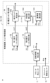
- 1 is a block diagram of a torque estimation device (control device) according to Embodiment 1.
- FIG. 1 is a hardware configuration diagram of a torque estimating device (control device) according to Embodiment 1.
- FIG. 6 is a time chart illustrating processing of the rotation information detection unit according to the first embodiment.
- FIG. 3 is a diagram illustrating the relationship between each cylinder and each stroke according to the first embodiment.
- FIG. 3 is a diagram illustrating torque characteristic data for a first estimated torque according to the first embodiment.
- FIG. 3 is a diagram illustrating calculation of the maximum value of angular acceleration of each cylinder according to the first embodiment.
- FIG. 3 is a diagram illustrating torque characteristic data for reference values according to the first embodiment.
- FIG. 2 is a block diagram of a torque estimating device (control device) according to a second embodiment.
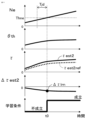
- 7 is a time chart for explaining error learning according to Embodiment 2.
- FIG. 7 is a time chart for explaining error learning according to Embodiment 2.
- Embodiment 1 A torque estimating device 100 for an internal combustion engine (hereinafter simply referred to as torque estimating device 100) according to a first embodiment will be described with reference to the drawings.
- FIG. 1 is a schematic configuration diagram of an internal combustion engine 1 and a torque estimating device 100 according to the present embodiment
- FIG. 2 is a block diagram of the torque estimating device 100 according to the present embodiment.
- torque estimating device 100 is incorporated in control device 50 of an internal combustion engine. Note that the torque estimating device 100 may be separate from the internal combustion engine control device 50.
- the internal combustion engine 1 includes a combustion chamber 7 (hereinafter also referred to as cylinder 7) that burns a mixture of air and fuel.
- the internal combustion engine 1 includes an intake pipe 23 that supplies air to the combustion chamber 7 and an exhaust pipe 17 that discharges exhaust gas burned in the combustion chamber 7.
- the internal combustion engine 1 is a gasoline engine.
- the internal combustion engine 1 includes a throttle valve 4 that opens and closes an intake pipe 23.
- the throttle valve 4 is an electronically controlled throttle valve that is driven to open and close by an electric motor controlled by a control device 50.
- the throttle valve 4 is provided with a throttle opening sensor 19 that outputs an electrical signal according to the opening of the throttle valve 4 .
- An air flow sensor 3 is provided in the intake pipe 23 on the upstream side of the throttle valve 4 and outputs an electrical signal according to the amount of intake air taken into the intake pipe 23.
- the internal combustion engine 1 includes an exhaust gas recirculation device 20 .
- the exhaust gas recirculation device 20 includes an EGR flow path 21 that recirculates exhaust gas from the exhaust pipe 17 to the intake manifold 12, and an EGR valve 22 that opens and closes the EGR flow path 21.
- the intake manifold 12 is a portion of the intake pipe 23 on the downstream side of the throttle valve 4.
- the EGR valve 22 is an electronically controlled EGR valve that is driven to open and close by an electric motor controlled by the control device 50.
- the exhaust pipe 17 is equipped with an air-fuel ratio sensor 18 that outputs an electrical signal according to the air-fuel ratio of exhaust gas within the exhaust pipe 17.
- the intake manifold 12 is provided with a gas pressure sensor 8 that outputs an electrical signal according to the pressure inside the intake manifold 12.
- An injector 13 that injects fuel is provided on the downstream side of the intake manifold 12. Note that the injector 13 may be provided to inject fuel directly into the cylinder 7.
- the internal combustion engine 1 is provided with an atmospheric pressure sensor 33 that outputs an electrical signal according to atmospheric pressure.
- the internal combustion engine 1 is provided with a water temperature sensor 34 that detects the temperature of cooling water.
- an ignition plug that ignites a mixture of air and fuel, and an ignition coil 16 that supplies ignition energy to the ignition plug.
- an intake valve 14 that adjusts the amount of intake air taken into the combustion chamber 7 from the intake pipe 23, and an intake valve 14 that adjusts the amount of exhaust gas discharged from the combustion chamber 7 to the exhaust pipe 17.
- An exhaust valve 15 is provided.
- the intake valve 14 is provided with an intake variable valve timing mechanism that changes the valve opening/closing timing.
- the exhaust valve 15 is provided with an exhaust variable valve timing mechanism that makes the valve opening/closing timing variable.
- the variable valve timing mechanisms 14 and 15 have electric actuators.
- the internal combustion engine 1 includes a plurality of combustion chambers 7 (four in this example).
- a piston 5 is provided within each combustion chamber 7.
- the piston 5 of each combustion chamber 7 is connected to the crankshaft 2 via a connecting rod 9 and a crank 32.
- the crankshaft 2 is rotationally driven by the reciprocating movement of the piston 5.
- the combustion gas pressure generated in each combustion chamber 7 presses the top surface of the piston 5 and rotates the crankshaft 2 via the connecting rod 9 and the crank 32.
- the crankshaft 2 is connected to a power transmission mechanism that transmits driving force to wheels, a generator, and the like.
- the power transmission mechanism includes a transmission and the like.
- the internal combustion engine 1 includes a rotor 31 that rotates integrally with the crankshaft 2.
- the rotor 31 is provided with a plurality of teeth at a plurality of predetermined crank angles.
- the rotor 31 has teeth arranged at 20 degree intervals.
- the teeth of the rotor 31 are provided with missing teeth where some of the teeth are missing.
- the internal combustion engine 1 is fixed to an engine block 24 and includes a crank angle sensor 11 that detects the teeth of a rotor 31.
- the internal combustion engine 1 includes a camshaft connected to a crankshaft by a chain.
- the camshaft opens and closes the intake valve 14 and the exhaust valve 15.
- the camshaft rotates once while the crankshaft 2 rotates twice.
- the internal combustion engine 1 includes a cam rotor that rotates integrally with a camshaft.
- a cam rotor is provided with a plurality of teeth at a plurality of predetermined camshaft angles.
- the internal combustion engine 1 is fixed to the engine block 24 and includes a cam angle sensor 30 (see FIG. 3) that detects teeth of a cam rotor.
- the control device 50 detects the crank angle with respect to the top dead center (TDC) of each piston 5 based on two types of output signals from the crank angle sensor 11 and the cam angle sensor 30, and also detects the crank angle of each combustion chamber 7. Determine the journey.
- the internal combustion engine 1 is a four-stroke engine having an intake stroke, a compression stroke, a combustion stroke, and an exhaust stroke.
- the crank angle sensor 11 and the cam angle sensor 30 output electrical signals according to changes in the distance between each sensor and the teeth due to the rotation of the crankshaft 2.
- the output signal of each angle sensor 11, 30 is a rectangular wave that turns on and off depending on whether the distance between the sensor and the tooth is close or far.
- an electromagnetic pickup type sensor is used for each angle sensor 11, 30, for example.
- the configuration of the internal combustion engine is not limited to the configuration described using FIG. 1, and internal combustion engines with various configurations may be used.
- the torque estimating device 100 is incorporated into a control device 50 for an internal combustion engine.
- the control device 50 includes processing units such as a rotation information detection unit 51, a first estimated torque calculation unit 52, a second estimated torque calculation unit 53, and a third estimated torque calculation unit 54.
- Each of the processing units 51 to 54 of the control device 50 is realized by a processing circuit included in the control device 50. Specifically, as shown in FIG.
- the control device 50 includes a processing circuit such as an arithmetic processing device 90 (computer) such as a CPU (Central Processing Unit), and a processing circuit connected to the arithmetic processing device 90 via a signal line such as a bus. It includes a connected storage device 91, an input circuit 92 that inputs external signals to the arithmetic processing device 90, an output circuit 93 that outputs signals from the arithmetic processing device 90 to the outside, and the like.
- a processing circuit such as an arithmetic processing device 90 (computer) such as a CPU (Central Processing Unit)
- a processing circuit connected to the arithmetic processing device 90 via a signal line such as a bus. It includes a connected storage device 91, an input circuit 92 that inputs external signals to the arithmetic processing device 90, an output circuit 93 that outputs signals from the arithmetic processing device 90 to the outside, and the like.
- the arithmetic processing unit 90 includes an ASIC (Application Specific Integrated Circuit), an IC (Integrated Circuit), a DSP (Digital Signal Processor), an FPGA (Field Programmable Gate Array), various logic circuits, and various signal processing circuits. It's okay. Further, a plurality of arithmetic processing units 90 of the same type or different types may be provided, and each process may be shared and executed.
- ASIC Application Specific Integrated Circuit
- IC Integrated Circuit
- DSP Digital Signal Processor
- FPGA Field Programmable Gate Array
- the storage device 91 includes volatile and nonvolatile storage devices such as RAM (Random Access Memory), ROM (Read Only Memory), and EEPROM (Electrically Erasable Programmable ROM).
- the input circuit 92 is connected to various sensors and switches, and includes an A/D converter and the like for inputting output signals of these sensors and switches to the arithmetic processing device 90.
- the output circuit 93 is connected to electrical loads and includes a drive circuit and the like for outputting control signals from the arithmetic processing device 90 to these electrical loads.
- the functions of the processing units 51 to 54 included in the control device 50 are executed by the arithmetic processing device 90 executing software (programs) stored in the storage device 91 such as ROM and EEPROM, and This is realized by cooperating with other hardware of the control device 50 such as the circuit 92 and the output circuit 93.
- setting data such as torque characteristic data for the first estimated torque, moment of inertia Icrk, load torque ⁇ load, torque characteristic data for reference value, etc. used by each of the processing units 51 to 54 etc. is stored in a storage device 91 such as ROM or EEPROM. is stored in In addition, each processing unit 51 to 54 etc.
- the input circuit 92 includes the crank angle sensor 11 , the cam angle sensor 30 , the water temperature sensor 34 , the air flow sensor 3 , the throttle opening sensor 19 , the gas pressure sensor 8 , the atmospheric pressure sensor 33 , and the air-fuel ratio sensor 18 , an accelerator position sensor 26, etc. are connected.
- the output circuit 93 is connected to the throttle valve 4 (electric motor), the EGR valve 22 (electric motor), the injector 13, the ignition coil 16, the intake variable valve timing mechanism 14, the exhaust variable valve timing mechanism 15, and the like.
- various sensors, switches, actuators, etc. (not shown) are connected to the torque estimating device 100.
- the control device 50 detects the operating state of the internal combustion engine 1, such as the throttle opening ⁇ th, the amount of intake air in the cylinder, the pressure in the intake manifold, the atmospheric pressure, and the air-fuel ratio, based on output signals from various sensors.
- the control device 50 calculates the fuel injection amount, ignition timing, etc. based on input output signals of various sensors, etc., and drives and controls the injector 13, ignition coil 16, etc.
- the control device 50 calculates the output torque of the internal combustion engine 1 requested by the driver based on the output signal of the accelerator position sensor 26, etc., and adjusts the throttle so that the amount of intake air achieves the requested output torque.
- Controls valve 4 etc. Specifically, the control device 50 calculates the target throttle opening and controls the electricity of the throttle valve 4 so that the throttle opening ⁇ th detected based on the output signal of the throttle opening sensor 19 approaches the target throttle opening. Drive and control the motor.
- control device 50 calculates a target opening degree of the EGR valve 22 based on input output signals of various sensors, etc., and drives and controls the electric motor of the EGR valve 22.
- the control device 50 calculates the target opening/closing timing of the intake valve and the target opening/closing timing of the exhaust valve based on the input output signals of various sensors, etc., and adjusts the intake and exhaust variable valve timing mechanism based on each target opening/closing timing. 14 and 15 are driven and controlled.
- Rotation information detection section 51 The rotation information detection unit 51 detects the rotation speed Ne and angular acceleration ⁇ d of the crankshaft of the internal combustion engine. In this embodiment, the rotation information detection unit 51 detects the crank angle ⁇ d based on the output signal of the crank angle sensor 11, and calculates the angular velocity ⁇ d, which is the time rate of change of the detected crank angle ⁇ d, and the time of the angular velocity ⁇ d. Calculate the angular acceleration ⁇ d, which is the rate of change. The rotation information detection unit 51 detects the rotation speed Ne of the crankshaft based on the output signal of the crank angle sensor 11. Note that the rotational speed Ne corresponds to the angular speed ⁇ d, but in this embodiment, it is the average speed of the stroke period.
- the rotation information detection unit 51 detects the crank angle ⁇ d based on the output signal of the crank angle sensor 11, and also detects the detection time Td at which the crank angle ⁇ d is detected. Then, the rotation information detection unit 51 calculates the corresponding angular interval ⁇ d and time interval ⁇ Td between the detected angles ⁇ d, based on the detected angle ⁇ d, which is the detected crank angle ⁇ d, and the detected time Td.
- the rotation information detection unit 51 determines the crank angle ⁇ d when the falling edge (or rising edge) of the output signal (rectangular wave) of the crank angle sensor 11 is detected.
- the rotation information detection unit 51 uses a known method to determine the crank angle with respect to the top dead center (TDC) of the piston of the first cylinder based on two types of output signals from the crank angle sensor 11 and the cam angle sensor 30.
- TDC top dead center
- the stroke of each cylinder 7 is determined.
- FIG. 5 shows strokes from the first cylinder to the fourth cylinder.
- the rotation information detection unit 51 calculates the angular velocity ⁇ d based on each crank angle ⁇ d and the detection time Td at which each crank angle ⁇ d is detected. For example, as shown in the following equation, the rotation information detection unit 51 calculates the angular interval ⁇ d(n) between the currently detected crank angle ⁇ d(n) and the previously detected crank angle ⁇ d(n-1), and the currently detected crank angle ⁇ d(n). The angular velocity ⁇ d(n) of the currently detected angle is calculated based on the time interval ⁇ Td(n) between the time Td(n) and the previous detection time Td(n-1). Note that various other known methods may be used to calculate the angular velocity ⁇ d.
- the rotation information detection unit 51 calculates the angular acceleration ⁇ d based on the angular velocity ⁇ d. For example, as shown in the following equation, the rotation information detection unit 51 calculates the angular velocity ⁇ d(n) calculated from the current detected angle, the angular velocity ⁇ d(n-1) calculated from the previous detected angle, and the time of the current detected angle. Based on the interval ⁇ Td(n), the angular acceleration ⁇ d(n) of the current detected angle is calculated. Note that various other known methods may be used to calculate the angular acceleration ⁇ d.
- the first estimated torque calculation unit 52 calculates the operating state for torque characteristic data of at least one of the throttle opening degree ⁇ th, the cylinder intake air amount, the fuel injection amount, and the rotational speed Ne, and the output torque of the internal combustion engine. Using the torque characteristic data for the first estimated torque whose relationship with the first estimated torque ⁇ est1 is set in advance, the first estimated torque ⁇ est1 corresponding to the current driving state for the torque characteristic data is calculated.
- the first estimated torque ⁇ est1 is a torque output from the crankshaft to the outside of the internal combustion engine, and is an average output torque during a stroke cycle.
- the torque characteristic data for the first estimated torque is map data in which the relationship between the throttle opening degree ⁇ th, the rotational speed Ne, and the first estimated torque ⁇ est1 is set in advance.
- the first estimated torque calculation unit 52 refers to the torque characteristic data for the first estimated torque and calculates the first estimated torque ⁇ est1 corresponding to the current throttle opening ⁇ th and rotational speed Ne.
- the cylinder intake air amount or the fuel injection amount may be used instead of the throttle opening ⁇ th. That is, it is preferable that parameters correlated to the rotational speed Ne and the fuel injection amount be used as the operating state for the torque characteristic data.
- various operating states of the internal combustion engine that correlate with the output torque such as EGR rate, ignition timing, intake valve opening/closing timing, and exhaust valve opening/closing timing, may be used as the operating state for the torque characteristic data.
- the torque characteristic data for the first estimated torque may be a combination of a plurality of map data, or a neural network or the like may be used.
- Second estimated torque calculation unit 53 The second estimated torque calculation unit 53 calculates a second estimated torque ⁇ est2, which is an estimated value of the torque of the crankshaft, based on the angular acceleration ⁇ d.
- the second estimated torque calculation unit 53 calculates the maximum value ⁇ max of the angular acceleration ⁇ d during the combustion stroke, and based on the maximum value ⁇ max of the angular acceleration, the second estimated torque calculation unit 53 calculates the maximum value ⁇ max of the angular acceleration ⁇ d during the combustion stroke.
- Estimated torque ⁇ est2 is calculated. According to this configuration, by calculating the maximum value ⁇ max of angular acceleration during the combustion stroke, the second estimated torque ⁇ est2 can be calculated using the maximum value ⁇ max of angular acceleration increased due to combustion, and the second estimated torque ⁇ est2 can be calculated using the maximum value ⁇ max of angular acceleration increased due to combustion. 2.
- the maximum value of the instantaneous torque increased mainly due to combustion can be calculated as the estimated torque ⁇ est2.
- the internal combustion engine 1 includes four combustion chambers 7 (cylinders 7).
- the second estimated torque calculation unit 53 calculates the maximum values ⁇ max1, ⁇ max2, ⁇ max3, and ⁇ max4 of the angular acceleration during the combustion stroke for each of the four combustion chambers 7, and calculates the maximum values ⁇ max1, ⁇ max2, ⁇ max3, ⁇ max4 of the angular acceleration for each of the four combustion chambers 7, as shown in the following equation.
- a second estimated torque ⁇ est2 is calculated based on the average value ⁇ maxave of the maximum value of the angular acceleration. The average value ⁇ maxave is calculated every two revolutions of the crankshaft.
- the second estimated torque calculation unit 53 calculates the second estimated torque ⁇ est2 by multiplying the angular acceleration ⁇ d (in this example, the inter-cylinder average value ⁇ maxave of the maximum value of angular acceleration) by the moment of inertia Icrk.
- the moment of inertia Icrk is the total value of the moments of inertia of each rotating member that rotates integrally with the crankshaft, and is set in advance.
- the second estimated torque calculation unit 53 calculates the second estimated torque ⁇ est2 by subtracting the load torque ⁇ load from the product of the angular acceleration ⁇ d and the moment of inertia Icrk.
- the load torque ⁇ load is various load torques applied to the crankshaft from the outside of the internal combustion engine, and usually takes a negative value. For example, a preset value is used for the load torque ⁇ load.
- the second estimated torque calculation unit 53 calculates the torque obtained by multiplying the angular acceleration ⁇ d near the top dead center (TDC) of the piston by the moment of inertia Icrk. , may be used as the load torque ⁇ load.
- the angle near top dead center may be set to an angle within a range from 10 degrees before top dead center to 10 degrees after top dead center, for example, TDC.
- TDC The angle near top dead center
- the connecting rod and the crank are in a straight line, and no shaft torque is generated due to the force of the cylinder pressure pushing the piston, so the load torque ⁇ load can be calculated.
- the load torque ⁇ load applied to the crankshaft from the outside of the internal combustion engine can be excluded, the amount of increase in the instantaneous torque increased due to combustion can be calculated, and the calculation accuracy of the second estimated torque ⁇ est2 can be improved. can be increased.
- the average angular acceleration during the stroke period may be used to calculate the second estimated torque ⁇ est2.
- Third estimated torque calculation unit 54 The third estimated torque calculation unit 54 learns the deviation ⁇ est2 between the second estimated torque ⁇ est2 and a preset reference value ⁇ est2ref of the second estimated torque as an error learning value ⁇ lrn, and uses the first estimated torque ⁇ est1 as an error learning value. The value corrected by the value ⁇ lrn is calculated as the third estimated torque ⁇ est3.
- the individual of the internal combustion engine 1 is It is possible to calculate a highly accurate torque estimate that reflects torque variations caused by variations, aging, and the like.
- control device 50 performs torque control to control the output torque of the internal combustion engine based on the third estimated torque ⁇ est3. For example, the control device 50 calculates the target throttle opening degree so that the third estimated torque ⁇ est3 approaches the required output torque. Further, the control device 50 transmits the third estimated torque ⁇ est3 to an external control device such as a vehicle control device or a motor control device, and causes it to be reflected in the torque control of the external control device.
- an external control device such as a vehicle control device or a motor control device
- the third estimated torque calculation section 54 includes a reference value calculation section 541, a learned value calculation section 542, and an estimated torque correction section 543.
- the reference value calculation unit 541 calculates the operating state for reference values of at least one of the throttle opening degree ⁇ th, the cylinder intake air amount, the fuel injection amount, and the rotational speed Ne, and the reference value ⁇ est2ref of the second estimated torque.
- a reference value ⁇ est2ref of the second estimated torque corresponding to the current operating state for the reference value is calculated using the torque characteristic data for the reference value in which the relationship is set in advance.
- the reference value ⁇ est2ref of the second estimated torque is the maximum value or increase amount of the instantaneous torque increased due to combustion, so the first estimated torque ⁇ est1, which is the average output torque during the stroke cycle, will have different values. Therefore, the torque characteristic data for the reference value is set to a different value from the torque characteristic data for the first estimated torque.
- the torque characteristic data for the reference value is map data in which the relationship between the throttle opening degree ⁇ th, the rotational speed Ne, and the reference value ⁇ est2ref of the second estimated torque is set in advance.
- the reference value calculation unit 541 refers to the torque characteristic data for the reference value and calculates the reference value ⁇ est2ref of the second estimated torque corresponding to the current throttle opening ⁇ th and rotational speed Ne.
- the cylinder intake air amount or the fuel injection amount may be used instead of the throttle opening ⁇ th. That is, it is preferable to use parameters correlated with the rotational speed Ne and the fuel injection amount as the operating state for the reference value.
- various operating states of the internal combustion engine that correlate with the output torque such as EGR rate, ignition timing, intake valve opening/closing timing, and exhaust valve opening/closing timing, may be used as the operating state for the reference value.
- the torque characteristic data for the reference value may be obtained by combining a plurality of map data, or by using a neural network or the like.
- the learning value calculation unit 542 updates the error learning value ⁇ lrn based on the deviation ⁇ est2 between the second estimated torque ⁇ est2 and the reference value ⁇ est2ref of the second estimated torque.
- the learning value calculation unit 542 performs statistical processing on the deviation ⁇ est2 to update the error learning value ⁇ lrn. For example, low-pass filter processing is performed as statistical processing.
- the learning value calculation unit 542 updates the error learning value ⁇ lrn using the following equation.
- (j) indicates the calculated value of the current update cycle
- (j-1) indicates the calculated value of the previous update cycle
- Kflt is the filter gain.
- the update period is set to a period in which the crankshaft rotates twice.
- the error learning value ⁇ lrn may be provided and updated for each operating state region of at least one of the throttle opening ⁇ th, the cylinder intake air amount, the fuel injection amount, and the rotational speed Ne.
- the estimated torque correction unit 543 calculates a value obtained by correcting the first estimated torque ⁇ est1 using the error learning value ⁇ lrn as the third estimated torque ⁇ est3. For example, the estimated torque correction unit 543 calculates the third estimated torque ⁇ est3 using the following equation.
- the estimated torque correction unit 543 calculates the correction coefficient K ⁇ based on the operating state for at least one correction coefficient of the throttle opening ⁇ th, the cylinder intake air amount, the fuel injection amount, and the rotational speed Ne. As shown in the following equation, a value obtained by adding the multiplication value of the error learning value ⁇ lrn and the correction coefficient K ⁇ to the first estimated torque ⁇ est1 may be calculated as the third estimated torque ⁇ est3.
- the correction accuracy can be improved by multiplying the error learning value ⁇ lrn by the correction coefficient K ⁇ .
- the proportionality coefficient of the average output torque during the stroke cycle with respect to the maximum value or increase amount of the instantaneous torque increased by combustion changes depending on the operating condition, it is corrected based on the operating condition for the correction coefficient.
- the correction accuracy can be improved by calculating the coefficient K ⁇ and multiplying the error learning value ⁇ lrn by the correction coefficient K ⁇ .
- the estimated torque correction unit 543 uses correction coefficient setting data for a reference value in which the relationship between the operating state for the correction coefficient and the correction coefficient K ⁇ is set in advance, and calculates the correction coefficient K ⁇ corresponding to the current operating state for the correction coefficient. Calculate.
- the correction coefficient setting data is configured in the same manner as the torque characteristic data for the reference value.
- Embodiment 2 A torque estimating device 100 according to a second embodiment will be described with reference to the drawings. Explanation of the same components as in the first embodiment described above will be omitted.
- the basic configuration of torque estimating device 100 according to this embodiment is the same as that of Embodiment 1. In this embodiment, a part of the processing of the third estimated torque calculation unit 54 is different from that in the first embodiment.
- a learning condition determining section 544 is provided.
- the learning condition determination unit 544 determines whether the learning condition is satisfied based on the operating state for learning determination of at least one of the throttle opening degree ⁇ th, the cylinder intake air amount, the fuel injection amount, and the rotational speed Ne. Determine whether The learning value calculation unit 542 updates the error learning value ⁇ lrn based on the deviation ⁇ est2 when the learning condition is satisfied.
- learning accuracy can be improved by performing learning when preset learning conditions are met.
- the learning condition determination unit 544 determines that when the rotation speed Ne passes a preset determination rotation speed Thne while the rotation speed Ne is increasing, It is determined that the learning condition is satisfied.
- the state in which the rotational speed Ne is accelerated and decelerated is a transient state in which the torque of the internal combustion engine increases and decreases, so if learning is performed in this transient state, learning accuracy is likely to deteriorate.
- the rotational speed Ne In a state where the rotational speed Ne is continuously increasing, the torque does not increase or decrease much and is stable, so that learning accuracy can be improved.
- the output of the internal combustion engine is smaller and the inertia is lower than that of four-wheeled vehicles, so learning accuracy tends to decrease due to variable factors, but the above configuration can suppress the decrease in learning accuracy. .
- the learning condition determination unit 544 determines that the learning condition is satisfied when the rotational speed Ne is continuously increasing during the determination period Tjd and the rotational speed Ne passes the determination rotational speed Thne. judge.
- the learning condition determining unit 544 determines that the rotational speed Ne is continuously increasing within a preset increase rate during the determination period Tjd, and that the rotational speed Ne is higher than the determination rotational speed Thne. When the learning condition is passed, it may be determined that the learning condition is satisfied.
- FIG. 10 the internal combustion engine is in a state where there are no individual variations or aging changes, the second estimated torque ⁇ est2 and the reference value ⁇ est2ref of the second estimated torque match, and the deviation ⁇ est2 is close to zero.
- the throttle opening ⁇ th increases, the torque increases, and the rotational speed Ne increases continuously. While the rotational speed Ne is increasing, the rotational speed Ne passes the determination rotational speed Thne at time t01, and the learning condition is satisfied.
- the deviation ⁇ est2 when the learning condition is satisfied is learned as the error learning value ⁇ lrn.
- FIG. 11 the internal combustion engine is in a state where there are individual variations and changes over time, the second estimated torque ⁇ est2 exceeds the second estimated torque reference value ⁇ est2ref, and the deviation ⁇ est2 is smaller than zero.
- the throttle opening ⁇ th increases, the torque increases, and the rotational speed Ne increases continuously. While the rotational speed Ne is increasing, the rotational speed Ne passes the determination rotational speed Thne at time t01, and the learning condition is satisfied.
- the deviation ⁇ est2 when the learning condition is satisfied is learned as the error learning value ⁇ lrn.
- the average value of the deviation ⁇ est2 obtained multiple times when the learning condition is satisfied multiple times may be learned as the error learning value ⁇ lrn.
Landscapes
- Engineering & Computer Science (AREA)
- Chemical & Material Sciences (AREA)
- Combustion & Propulsion (AREA)
- Mechanical Engineering (AREA)
- General Engineering & Computer Science (AREA)
- Physics & Mathematics (AREA)
- General Physics & Mathematics (AREA)
- Combined Controls Of Internal Combustion Engines (AREA)
Priority Applications (4)
| Application Number | Priority Date | Filing Date | Title |
|---|---|---|---|
| JP2024528023A JP7621562B2 (ja) | 2022-06-16 | 2022-06-16 | 内燃機関のトルク推定装置 |
| US18/871,633 US12565863B2 (en) | 2022-06-16 | 2022-06-16 | Torque estimation apparatus for internal combustion engine |
| EP22946852.5A EP4542021A4 (en) | 2022-06-16 | 2022-06-16 | TORQUE ESTIMATING DEVICE FOR INTERNAL COMBUSTION ENGINES |
| PCT/JP2022/024115 WO2023243035A1 (ja) | 2022-06-16 | 2022-06-16 | 内燃機関のトルク推定装置 |
Applications Claiming Priority (1)
| Application Number | Priority Date | Filing Date | Title |
|---|---|---|---|
| PCT/JP2022/024115 WO2023243035A1 (ja) | 2022-06-16 | 2022-06-16 | 内燃機関のトルク推定装置 |
Publications (1)
| Publication Number | Publication Date |
|---|---|
| WO2023243035A1 true WO2023243035A1 (ja) | 2023-12-21 |
Family
ID=89192501
Family Applications (1)
| Application Number | Title | Priority Date | Filing Date |
|---|---|---|---|
| PCT/JP2022/024115 Ceased WO2023243035A1 (ja) | 2022-06-16 | 2022-06-16 | 内燃機関のトルク推定装置 |
Country Status (4)
| Country | Link |
|---|---|
| US (1) | US12565863B2 (https=) |
| EP (1) | EP4542021A4 (https=) |
| JP (1) | JP7621562B2 (https=) |
| WO (1) | WO2023243035A1 (https=) |
Citations (5)
| Publication number | Priority date | Publication date | Assignee | Title |
|---|---|---|---|---|
| JP2005016425A (ja) * | 2003-06-26 | 2005-01-20 | Mitsubishi Motors Corp | アイドル運転時空気量制御装置及びアイドル運転時空気量制御方法 |
| JP2005291174A (ja) | 2004-04-05 | 2005-10-20 | Denso Corp | 車両用エンジンのトルク制御装置 |
| JP2006183506A (ja) * | 2004-12-27 | 2006-07-13 | Hitachi Ltd | エンジンの制御装置 |
| JP2009275618A (ja) * | 2008-05-15 | 2009-11-26 | Mitsubishi Electric Corp | 角速度及び角加速度算出装置、トルク推定装置、燃焼状態推定装置 |
| JP2017106393A (ja) * | 2015-12-10 | 2017-06-15 | 富士通株式会社 | 推定装置、推定方法、推定プログラム、エンジンシステム、および移動装置 |
Family Cites Families (13)
| Publication number | Priority date | Publication date | Assignee | Title |
|---|---|---|---|---|
| JPH07332479A (ja) * | 1994-06-06 | 1995-12-22 | Hitachi Ltd | トルク補正装置 |
| GB2313927B (en) * | 1996-06-03 | 1999-06-23 | Nissan Motor | EGR control apparatus for internal combustion engine |
| DE19733106A1 (de) | 1997-07-31 | 1999-02-04 | Siemens Ag | Verfahren zum Steuern einer Brennkraftmaschine |
| WO2002071308A1 (en) * | 2001-03-05 | 2002-09-12 | The Ohio State University | Engine control using torque estimation |
| DE10305092B4 (de) | 2003-02-07 | 2007-05-03 | Siemens Ag | Verfahren zur automatischen Anpassung eines Drehmomentenmodells sowie Schaltungsanordnung |
| JP4435725B2 (ja) * | 2005-10-05 | 2010-03-24 | 本田技研工業株式会社 | 車両の駆動トルク推定装置および駆動トルク推定方法、並びに四輪駆動車両 |
| US9002550B2 (en) * | 2007-07-02 | 2015-04-07 | GM Global Technology Operations LLC | Use of torque model at virtual engine conditions |
| JP2013068146A (ja) * | 2011-09-22 | 2013-04-18 | Nissan Motor Co Ltd | 内燃機関のエンジントルク推定装置 |
| JP2014009641A (ja) * | 2012-06-29 | 2014-01-20 | Honda Motor Co Ltd | 車両用駆動力制御装置 |
| FR3030631B1 (fr) | 2014-12-23 | 2016-12-23 | Continental Automotive France | Procede de determination du couple moteur delivre par un moteur multicylindre |
| DE102015102249B4 (de) | 2015-02-17 | 2017-10-12 | Maridis GmbH | Verfahren und Vorrichtung zur Bestimmung der Leistungsverteilung einer Verbrennungskraftmaschine aus dem an der Kurbelwelle gemessenem Drehungleichförmigkeitsverlauf |
| WO2019058534A1 (ja) * | 2017-09-22 | 2019-03-28 | 株式会社トランストロン | インジェクタ噴射量制御装置、インジェクタ噴射量制御方法、プログラム、及び記憶媒体 |
| JP7101841B1 (ja) * | 2021-04-16 | 2022-07-15 | 三菱電機株式会社 | 内燃機関の制御装置及び制御方法 |
-
2022
- 2022-06-16 JP JP2024528023A patent/JP7621562B2/ja active Active
- 2022-06-16 US US18/871,633 patent/US12565863B2/en active Active
- 2022-06-16 WO PCT/JP2022/024115 patent/WO2023243035A1/ja not_active Ceased
- 2022-06-16 EP EP22946852.5A patent/EP4542021A4/en active Pending
Patent Citations (5)
| Publication number | Priority date | Publication date | Assignee | Title |
|---|---|---|---|---|
| JP2005016425A (ja) * | 2003-06-26 | 2005-01-20 | Mitsubishi Motors Corp | アイドル運転時空気量制御装置及びアイドル運転時空気量制御方法 |
| JP2005291174A (ja) | 2004-04-05 | 2005-10-20 | Denso Corp | 車両用エンジンのトルク制御装置 |
| JP2006183506A (ja) * | 2004-12-27 | 2006-07-13 | Hitachi Ltd | エンジンの制御装置 |
| JP2009275618A (ja) * | 2008-05-15 | 2009-11-26 | Mitsubishi Electric Corp | 角速度及び角加速度算出装置、トルク推定装置、燃焼状態推定装置 |
| JP2017106393A (ja) * | 2015-12-10 | 2017-06-15 | 富士通株式会社 | 推定装置、推定方法、推定プログラム、エンジンシステム、および移動装置 |
Non-Patent Citations (1)
| Title |
|---|
| See also references of EP4542021A4 |
Also Published As
| Publication number | Publication date |
|---|---|
| US12565863B2 (en) | 2026-03-03 |
| EP4542021A4 (en) | 2025-08-13 |
| EP4542021A1 (en) | 2025-04-23 |
| JPWO2023243035A1 (https=) | 2023-12-21 |
| JP7621562B2 (ja) | 2025-01-24 |
| US20250361841A1 (en) | 2025-11-27 |
Similar Documents
| Publication | Publication Date | Title |
|---|---|---|
| JP7146131B1 (ja) | 内燃機関の制御装置 | |
| US11480121B2 (en) | Controller and control method for internal combustion engine | |
| US20220333538A1 (en) | Controller and control method for internal combustion engine | |
| US11555462B2 (en) | Controller and control method for internal combustion engine | |
| US8818689B2 (en) | Cylinder intake air amount calculating apparatus for internal combustion engine | |
| JP7246548B1 (ja) | 内燃機関の制御装置 | |
| JP7030884B2 (ja) | 内燃機関の制御装置 | |
| US20230184187A1 (en) | Controller for internal combustion engine | |
| US10113490B2 (en) | Control apparatus for internal combustion engine | |
| JP7621562B2 (ja) | 内燃機関のトルク推定装置 | |
| US11703418B2 (en) | Controller for internal combustion engine | |
| JP2026065193A (ja) | 内燃機関の制御装置 | |
| US11686266B2 (en) | Controller for internal combustion engine | |
| JP7814617B2 (ja) | 内燃機関の制御装置 | |
| JP7756839B2 (ja) | 内燃機関の制御装置 | |
| US20230184186A1 (en) | Controller for internal combustion engine | |
| JP6910512B1 (ja) | 内燃機関の制御装置 | |
| WO2025187039A1 (ja) | 内燃機関の制御装置 | |
| WO2025197019A1 (ja) | 内燃機関の制御装置 | |
| WO2025182061A1 (ja) | 内燃機関の制御装置 |
Legal Events
| Date | Code | Title | Description |
|---|---|---|---|
| 121 | Ep: the epo has been informed by wipo that ep was designated in this application |
Ref document number: 22946852 Country of ref document: EP Kind code of ref document: A1 |
|
| WWE | Wipo information: entry into national phase |
Ref document number: 2024528023 Country of ref document: JP |
|
| WWE | Wipo information: entry into national phase |
Ref document number: 18871633 Country of ref document: US |
|
| WWE | Wipo information: entry into national phase |
Ref document number: 2022946852 Country of ref document: EP |
|
| NENP | Non-entry into the national phase |
Ref country code: DE |
|
| ENP | Entry into the national phase |
Ref document number: 2022946852 Country of ref document: EP Effective date: 20250116 |
|
| WWP | Wipo information: published in national office |
Ref document number: 2022946852 Country of ref document: EP |
|
| WWP | Wipo information: published in national office |
Ref document number: 18871633 Country of ref document: US |
|
| WWG | Wipo information: grant in national office |
Ref document number: 18871633 Country of ref document: US |