WO2023243035A1 - 内燃機関のトルク推定装置 - Google Patents
内燃機関のトルク推定装置 Download PDFInfo
- Publication number
- WO2023243035A1 WO2023243035A1 PCT/JP2022/024115 JP2022024115W WO2023243035A1 WO 2023243035 A1 WO2023243035 A1 WO 2023243035A1 JP 2022024115 W JP2022024115 W JP 2022024115W WO 2023243035 A1 WO2023243035 A1 WO 2023243035A1
- Authority
- WO
- WIPO (PCT)
- Prior art keywords
- torque
- estimated torque
- internal combustion
- estimated
- value
- Prior art date
Links
- 238000002485 combustion reaction Methods 0.000 title claims abstract description 107
- 230000001133 acceleration Effects 0.000 claims abstract description 36
- 238000004364 calculation method Methods 0.000 claims description 46
- 239000000446 fuel Substances 0.000 claims description 24
- 238000001514 detection method Methods 0.000 claims description 20
- 238000002347 injection Methods 0.000 claims description 16
- 239000007924 injection Substances 0.000 claims description 16
- 238000010586 diagram Methods 0.000 description 10
- 239000007789 gas Substances 0.000 description 8
- 230000007246 mechanism Effects 0.000 description 8
- 230000000875 corresponding effect Effects 0.000 description 7
- 230000007423 decrease Effects 0.000 description 6
- 238000000034 method Methods 0.000 description 6
- 230000032683 aging Effects 0.000 description 3
- 230000005540 biological transmission Effects 0.000 description 3
- 238000013459 approach Methods 0.000 description 2
- 238000013528 artificial neural network Methods 0.000 description 2
- 230000002596 correlated effect Effects 0.000 description 2
- 230000006870 function Effects 0.000 description 2
- 239000000203 mixture Substances 0.000 description 2
- 230000001052 transient effect Effects 0.000 description 2
- XLYOFNOQVPJJNP-UHFFFAOYSA-N water Substances O XLYOFNOQVPJJNP-UHFFFAOYSA-N 0.000 description 2
- 230000006399 behavior Effects 0.000 description 1
- 239000000567 combustion gas Substances 0.000 description 1
- 230000006835 compression Effects 0.000 description 1
- 238000007906 compression Methods 0.000 description 1
- 239000000498 cooling water Substances 0.000 description 1
- 230000005611 electricity Effects 0.000 description 1
- 230000000630 rising effect Effects 0.000 description 1
- 238000011144 upstream manufacturing Methods 0.000 description 1
Images


Classifications
-
- F—MECHANICAL ENGINEERING; LIGHTING; HEATING; WEAPONS; BLASTING
- F02—COMBUSTION ENGINES; HOT-GAS OR COMBUSTION-PRODUCT ENGINE PLANTS
- F02D—CONTROLLING COMBUSTION ENGINES
- F02D45/00—Electrical control not provided for in groups F02D41/00 - F02D43/00
Definitions
- the present application relates to a torque estimating device for an internal combustion engine.
- the output torque of the internal combustion engine is estimated using the torque characteristics of the internal combustion engine based on the operating conditions that affect the output torque, such as the throttle opening, intake air amount, and fuel injection amount. There is. Furthermore, in the technique disclosed in Patent Document 1, the output torque of the internal combustion engine is estimated based on the characteristics of the torque converter, and the torque estimation error is learned.
- Patent Document 1 uses the characteristics of a torque converter, which is a device external to the internal combustion engine, to learn variations in output torque caused by individual differences in internal combustion engines and changes over time.
- a torque converter which is a device external to the internal combustion engine
- an object of the present application is to provide an internal combustion engine torque estimating device that can accurately learn variations in the output torque of an internal combustion engine caused by individual differences in internal combustion engines and changes over time.
- the torque estimating device for an internal combustion engine includes: a rotation information detection unit that detects the rotation speed and angular acceleration of the crankshaft of the internal combustion engine; The relationship between the operating state for torque characteristic data of at least one of the throttle opening, the cylinder intake air amount, the fuel injection amount, and the rotation speed and the first estimated torque as the output torque of the internal combustion engine is determined in advance.
- a first estimated torque calculation unit that uses the set torque characteristic data for the first estimated torque to calculate the first estimated torque corresponding to the current driving state for the torque characteristic data
- a second estimated torque calculation unit that calculates a second estimated torque that is an estimated value of the torque of the crankshaft based on the angular acceleration; The deviation between the second estimated torque and a preset reference value of the second estimated torque is learned as an error learning value, and a value obtained by correcting the first estimated torque by the error learning value is used as a third estimated torque.
- a third estimated torque calculation unit that calculates the torque as shown in FIG.
- the internal combustion engine torque estimation device by comparing the second estimated torque calculated based on the actually detected angular acceleration with the reference value of the second estimated torque, Torque variations caused by changes etc. can be learned as error learning values. Then, by correcting the first estimated torque calculated based on the torque characteristic data of a preset reference state using the error learning value and calculating the third estimated torque, individual variations in the internal combustion engine, aging changes, etc. It is possible to calculate a highly accurate torque estimation value that reflects torque variations caused by the above.
- FIG. 1 is a schematic configuration diagram of an internal combustion engine and a torque estimating device (control device) according to a first embodiment.
- 1 is a block diagram of a torque estimation device (control device) according to Embodiment 1.
- FIG. 1 is a hardware configuration diagram of a torque estimating device (control device) according to Embodiment 1.
- FIG. 6 is a time chart illustrating processing of the rotation information detection unit according to the first embodiment.
- FIG. 3 is a diagram illustrating the relationship between each cylinder and each stroke according to the first embodiment.
- FIG. 3 is a diagram illustrating torque characteristic data for a first estimated torque according to the first embodiment.
- FIG. 3 is a diagram illustrating calculation of the maximum value of angular acceleration of each cylinder according to the first embodiment.
- FIG. 3 is a diagram illustrating torque characteristic data for reference values according to the first embodiment.
- FIG. 2 is a block diagram of a torque estimating device (control device) according to a second embodiment.
- 7 is a time chart for explaining error learning according to Embodiment 2.
- FIG. 7 is a time chart for explaining error learning according to Embodiment 2.
- Embodiment 1 A torque estimating device 100 for an internal combustion engine (hereinafter simply referred to as torque estimating device 100) according to a first embodiment will be described with reference to the drawings.
- FIG. 1 is a schematic configuration diagram of an internal combustion engine 1 and a torque estimating device 100 according to the present embodiment
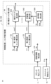
- FIG. 2 is a block diagram of the torque estimating device 100 according to the present embodiment.
- torque estimating device 100 is incorporated in control device 50 of an internal combustion engine. Note that the torque estimating device 100 may be separate from the internal combustion engine control device 50.
- the internal combustion engine 1 includes a combustion chamber 7 (hereinafter also referred to as cylinder 7) that burns a mixture of air and fuel.
- the internal combustion engine 1 includes an intake pipe 23 that supplies air to the combustion chamber 7 and an exhaust pipe 17 that discharges exhaust gas burned in the combustion chamber 7.
- the internal combustion engine 1 is a gasoline engine.
- the internal combustion engine 1 includes a throttle valve 4 that opens and closes an intake pipe 23.
- the throttle valve 4 is an electronically controlled throttle valve that is driven to open and close by an electric motor controlled by a control device 50.
- the throttle valve 4 is provided with a throttle opening sensor 19 that outputs an electrical signal according to the opening of the throttle valve 4 .
- An air flow sensor 3 is provided in the intake pipe 23 on the upstream side of the throttle valve 4 and outputs an electrical signal according to the amount of intake air taken into the intake pipe 23.
- the internal combustion engine 1 includes an exhaust gas recirculation device 20 .
- the exhaust gas recirculation device 20 includes an EGR flow path 21 that recirculates exhaust gas from the exhaust pipe 17 to the intake manifold 12, and an EGR valve 22 that opens and closes the EGR flow path 21.
- the intake manifold 12 is a portion of the intake pipe 23 on the downstream side of the throttle valve 4.
- the EGR valve 22 is an electronically controlled EGR valve that is driven to open and close by an electric motor controlled by the control device 50.
- the exhaust pipe 17 is equipped with an air-fuel ratio sensor 18 that outputs an electrical signal according to the air-fuel ratio of exhaust gas within the exhaust pipe 17.
- the intake manifold 12 is provided with a gas pressure sensor 8 that outputs an electrical signal according to the pressure inside the intake manifold 12.
- An injector 13 that injects fuel is provided on the downstream side of the intake manifold 12. Note that the injector 13 may be provided to inject fuel directly into the cylinder 7.
- the internal combustion engine 1 is provided with an atmospheric pressure sensor 33 that outputs an electrical signal according to atmospheric pressure.
- the internal combustion engine 1 is provided with a water temperature sensor 34 that detects the temperature of cooling water.
- an ignition plug that ignites a mixture of air and fuel, and an ignition coil 16 that supplies ignition energy to the ignition plug.
- an intake valve 14 that adjusts the amount of intake air taken into the combustion chamber 7 from the intake pipe 23, and an intake valve 14 that adjusts the amount of exhaust gas discharged from the combustion chamber 7 to the exhaust pipe 17.
- An exhaust valve 15 is provided.
- the intake valve 14 is provided with an intake variable valve timing mechanism that changes the valve opening/closing timing.
- the exhaust valve 15 is provided with an exhaust variable valve timing mechanism that makes the valve opening/closing timing variable.
- the variable valve timing mechanisms 14 and 15 have electric actuators.
- the internal combustion engine 1 includes a plurality of combustion chambers 7 (four in this example).
- a piston 5 is provided within each combustion chamber 7.
- the piston 5 of each combustion chamber 7 is connected to the crankshaft 2 via a connecting rod 9 and a crank 32.
- the crankshaft 2 is rotationally driven by the reciprocating movement of the piston 5.
- the combustion gas pressure generated in each combustion chamber 7 presses the top surface of the piston 5 and rotates the crankshaft 2 via the connecting rod 9 and the crank 32.
- the crankshaft 2 is connected to a power transmission mechanism that transmits driving force to wheels, a generator, and the like.
- the power transmission mechanism includes a transmission and the like.
- the internal combustion engine 1 includes a rotor 31 that rotates integrally with the crankshaft 2.
- the rotor 31 is provided with a plurality of teeth at a plurality of predetermined crank angles.
- the rotor 31 has teeth arranged at 20 degree intervals.
- the teeth of the rotor 31 are provided with missing teeth where some of the teeth are missing.
- the internal combustion engine 1 is fixed to an engine block 24 and includes a crank angle sensor 11 that detects the teeth of a rotor 31.
- the internal combustion engine 1 includes a camshaft connected to a crankshaft by a chain.
- the camshaft opens and closes the intake valve 14 and the exhaust valve 15.
- the camshaft rotates once while the crankshaft 2 rotates twice.
- the internal combustion engine 1 includes a cam rotor that rotates integrally with a camshaft.
- a cam rotor is provided with a plurality of teeth at a plurality of predetermined camshaft angles.
- the internal combustion engine 1 is fixed to the engine block 24 and includes a cam angle sensor 30 (see FIG. 3) that detects teeth of a cam rotor.
- the control device 50 detects the crank angle with respect to the top dead center (TDC) of each piston 5 based on two types of output signals from the crank angle sensor 11 and the cam angle sensor 30, and also detects the crank angle of each combustion chamber 7. Determine the journey.
- the internal combustion engine 1 is a four-stroke engine having an intake stroke, a compression stroke, a combustion stroke, and an exhaust stroke.
- the crank angle sensor 11 and the cam angle sensor 30 output electrical signals according to changes in the distance between each sensor and the teeth due to the rotation of the crankshaft 2.
- the output signal of each angle sensor 11, 30 is a rectangular wave that turns on and off depending on whether the distance between the sensor and the tooth is close or far.
- an electromagnetic pickup type sensor is used for each angle sensor 11, 30, for example.
- the configuration of the internal combustion engine is not limited to the configuration described using FIG. 1, and internal combustion engines with various configurations may be used.
- the torque estimating device 100 is incorporated into a control device 50 for an internal combustion engine.
- the control device 50 includes processing units such as a rotation information detection unit 51, a first estimated torque calculation unit 52, a second estimated torque calculation unit 53, and a third estimated torque calculation unit 54.
- Each of the processing units 51 to 54 of the control device 50 is realized by a processing circuit included in the control device 50. Specifically, as shown in FIG.
- the control device 50 includes a processing circuit such as an arithmetic processing device 90 (computer) such as a CPU (Central Processing Unit), and a processing circuit connected to the arithmetic processing device 90 via a signal line such as a bus. It includes a connected storage device 91, an input circuit 92 that inputs external signals to the arithmetic processing device 90, an output circuit 93 that outputs signals from the arithmetic processing device 90 to the outside, and the like.
- a processing circuit such as an arithmetic processing device 90 (computer) such as a CPU (Central Processing Unit)
- a processing circuit connected to the arithmetic processing device 90 via a signal line such as a bus. It includes a connected storage device 91, an input circuit 92 that inputs external signals to the arithmetic processing device 90, an output circuit 93 that outputs signals from the arithmetic processing device 90 to the outside, and the like.
- the arithmetic processing unit 90 includes an ASIC (Application Specific Integrated Circuit), an IC (Integrated Circuit), a DSP (Digital Signal Processor), an FPGA (Field Programmable Gate Array), various logic circuits, and various signal processing circuits. It's okay. Further, a plurality of arithmetic processing units 90 of the same type or different types may be provided, and each process may be shared and executed.
- ASIC Application Specific Integrated Circuit
- IC Integrated Circuit
- DSP Digital Signal Processor
- FPGA Field Programmable Gate Array
- the storage device 91 includes volatile and nonvolatile storage devices such as RAM (Random Access Memory), ROM (Read Only Memory), and EEPROM (Electrically Erasable Programmable ROM).
- the input circuit 92 is connected to various sensors and switches, and includes an A/D converter and the like for inputting output signals of these sensors and switches to the arithmetic processing device 90.
- the output circuit 93 is connected to electrical loads and includes a drive circuit and the like for outputting control signals from the arithmetic processing device 90 to these electrical loads.
- the functions of the processing units 51 to 54 included in the control device 50 are executed by the arithmetic processing device 90 executing software (programs) stored in the storage device 91 such as ROM and EEPROM, and This is realized by cooperating with other hardware of the control device 50 such as the circuit 92 and the output circuit 93.
- setting data such as torque characteristic data for the first estimated torque, moment of inertia Icrk, load torque ⁇ load, torque characteristic data for reference value, etc. used by each of the processing units 51 to 54 etc. is stored in a storage device 91 such as ROM or EEPROM. is stored in In addition, each processing unit 51 to 54 etc.
- the input circuit 92 includes the crank angle sensor 11 , the cam angle sensor 30 , the water temperature sensor 34 , the air flow sensor 3 , the throttle opening sensor 19 , the gas pressure sensor 8 , the atmospheric pressure sensor 33 , and the air-fuel ratio sensor 18 , an accelerator position sensor 26, etc. are connected.
- the output circuit 93 is connected to the throttle valve 4 (electric motor), the EGR valve 22 (electric motor), the injector 13, the ignition coil 16, the intake variable valve timing mechanism 14, the exhaust variable valve timing mechanism 15, and the like.
- various sensors, switches, actuators, etc. (not shown) are connected to the torque estimating device 100.
- the control device 50 detects the operating state of the internal combustion engine 1, such as the throttle opening ⁇ th, the amount of intake air in the cylinder, the pressure in the intake manifold, the atmospheric pressure, and the air-fuel ratio, based on output signals from various sensors.
- the control device 50 calculates the fuel injection amount, ignition timing, etc. based on input output signals of various sensors, etc., and drives and controls the injector 13, ignition coil 16, etc.
- the control device 50 calculates the output torque of the internal combustion engine 1 requested by the driver based on the output signal of the accelerator position sensor 26, etc., and adjusts the throttle so that the amount of intake air achieves the requested output torque.
- Controls valve 4 etc. Specifically, the control device 50 calculates the target throttle opening and controls the electricity of the throttle valve 4 so that the throttle opening ⁇ th detected based on the output signal of the throttle opening sensor 19 approaches the target throttle opening. Drive and control the motor.
- control device 50 calculates a target opening degree of the EGR valve 22 based on input output signals of various sensors, etc., and drives and controls the electric motor of the EGR valve 22.
- the control device 50 calculates the target opening/closing timing of the intake valve and the target opening/closing timing of the exhaust valve based on the input output signals of various sensors, etc., and adjusts the intake and exhaust variable valve timing mechanism based on each target opening/closing timing. 14 and 15 are driven and controlled.
- Rotation information detection section 51 The rotation information detection unit 51 detects the rotation speed Ne and angular acceleration ⁇ d of the crankshaft of the internal combustion engine. In this embodiment, the rotation information detection unit 51 detects the crank angle ⁇ d based on the output signal of the crank angle sensor 11, and calculates the angular velocity ⁇ d, which is the time rate of change of the detected crank angle ⁇ d, and the time of the angular velocity ⁇ d. Calculate the angular acceleration ⁇ d, which is the rate of change. The rotation information detection unit 51 detects the rotation speed Ne of the crankshaft based on the output signal of the crank angle sensor 11. Note that the rotational speed Ne corresponds to the angular speed ⁇ d, but in this embodiment, it is the average speed of the stroke period.
- the rotation information detection unit 51 detects the crank angle ⁇ d based on the output signal of the crank angle sensor 11, and also detects the detection time Td at which the crank angle ⁇ d is detected. Then, the rotation information detection unit 51 calculates the corresponding angular interval ⁇ d and time interval ⁇ Td between the detected angles ⁇ d, based on the detected angle ⁇ d, which is the detected crank angle ⁇ d, and the detected time Td.
- the rotation information detection unit 51 determines the crank angle ⁇ d when the falling edge (or rising edge) of the output signal (rectangular wave) of the crank angle sensor 11 is detected.
- the rotation information detection unit 51 uses a known method to determine the crank angle with respect to the top dead center (TDC) of the piston of the first cylinder based on two types of output signals from the crank angle sensor 11 and the cam angle sensor 30.
- TDC top dead center
- the stroke of each cylinder 7 is determined.
- FIG. 5 shows strokes from the first cylinder to the fourth cylinder.
- the rotation information detection unit 51 calculates the angular velocity ⁇ d based on each crank angle ⁇ d and the detection time Td at which each crank angle ⁇ d is detected. For example, as shown in the following equation, the rotation information detection unit 51 calculates the angular interval ⁇ d(n) between the currently detected crank angle ⁇ d(n) and the previously detected crank angle ⁇ d(n-1), and the currently detected crank angle ⁇ d(n). The angular velocity ⁇ d(n) of the currently detected angle is calculated based on the time interval ⁇ Td(n) between the time Td(n) and the previous detection time Td(n-1). Note that various other known methods may be used to calculate the angular velocity ⁇ d.
- the rotation information detection unit 51 calculates the angular acceleration ⁇ d based on the angular velocity ⁇ d. For example, as shown in the following equation, the rotation information detection unit 51 calculates the angular velocity ⁇ d(n) calculated from the current detected angle, the angular velocity ⁇ d(n-1) calculated from the previous detected angle, and the time of the current detected angle. Based on the interval ⁇ Td(n), the angular acceleration ⁇ d(n) of the current detected angle is calculated. Note that various other known methods may be used to calculate the angular acceleration ⁇ d.
- the first estimated torque calculation unit 52 calculates the operating state for torque characteristic data of at least one of the throttle opening degree ⁇ th, the cylinder intake air amount, the fuel injection amount, and the rotational speed Ne, and the output torque of the internal combustion engine. Using the torque characteristic data for the first estimated torque whose relationship with the first estimated torque ⁇ est1 is set in advance, the first estimated torque ⁇ est1 corresponding to the current driving state for the torque characteristic data is calculated.
- the first estimated torque ⁇ est1 is a torque output from the crankshaft to the outside of the internal combustion engine, and is an average output torque during a stroke cycle.
- the torque characteristic data for the first estimated torque is map data in which the relationship between the throttle opening degree ⁇ th, the rotational speed Ne, and the first estimated torque ⁇ est1 is set in advance.
- the first estimated torque calculation unit 52 refers to the torque characteristic data for the first estimated torque and calculates the first estimated torque ⁇ est1 corresponding to the current throttle opening ⁇ th and rotational speed Ne.
- the cylinder intake air amount or the fuel injection amount may be used instead of the throttle opening ⁇ th. That is, it is preferable that parameters correlated to the rotational speed Ne and the fuel injection amount be used as the operating state for the torque characteristic data.
- various operating states of the internal combustion engine that correlate with the output torque such as EGR rate, ignition timing, intake valve opening/closing timing, and exhaust valve opening/closing timing, may be used as the operating state for the torque characteristic data.
- the torque characteristic data for the first estimated torque may be a combination of a plurality of map data, or a neural network or the like may be used.
- Second estimated torque calculation unit 53 The second estimated torque calculation unit 53 calculates a second estimated torque ⁇ est2, which is an estimated value of the torque of the crankshaft, based on the angular acceleration ⁇ d.
- the second estimated torque calculation unit 53 calculates the maximum value ⁇ max of the angular acceleration ⁇ d during the combustion stroke, and based on the maximum value ⁇ max of the angular acceleration, the second estimated torque calculation unit 53 calculates the maximum value ⁇ max of the angular acceleration ⁇ d during the combustion stroke.
- Estimated torque ⁇ est2 is calculated. According to this configuration, by calculating the maximum value ⁇ max of angular acceleration during the combustion stroke, the second estimated torque ⁇ est2 can be calculated using the maximum value ⁇ max of angular acceleration increased due to combustion, and the second estimated torque ⁇ est2 can be calculated using the maximum value ⁇ max of angular acceleration increased due to combustion. 2.
- the maximum value of the instantaneous torque increased mainly due to combustion can be calculated as the estimated torque ⁇ est2.
- the internal combustion engine 1 includes four combustion chambers 7 (cylinders 7).
- the second estimated torque calculation unit 53 calculates the maximum values ⁇ max1, ⁇ max2, ⁇ max3, and ⁇ max4 of the angular acceleration during the combustion stroke for each of the four combustion chambers 7, and calculates the maximum values ⁇ max1, ⁇ max2, ⁇ max3, ⁇ max4 of the angular acceleration for each of the four combustion chambers 7, as shown in the following equation.
- a second estimated torque ⁇ est2 is calculated based on the average value ⁇ maxave of the maximum value of the angular acceleration. The average value ⁇ maxave is calculated every two revolutions of the crankshaft.
- the second estimated torque calculation unit 53 calculates the second estimated torque ⁇ est2 by multiplying the angular acceleration ⁇ d (in this example, the inter-cylinder average value ⁇ maxave of the maximum value of angular acceleration) by the moment of inertia Icrk.
- the moment of inertia Icrk is the total value of the moments of inertia of each rotating member that rotates integrally with the crankshaft, and is set in advance.
- the second estimated torque calculation unit 53 calculates the second estimated torque ⁇ est2 by subtracting the load torque ⁇ load from the product of the angular acceleration ⁇ d and the moment of inertia Icrk.
- the load torque ⁇ load is various load torques applied to the crankshaft from the outside of the internal combustion engine, and usually takes a negative value. For example, a preset value is used for the load torque ⁇ load.
- the second estimated torque calculation unit 53 calculates the torque obtained by multiplying the angular acceleration ⁇ d near the top dead center (TDC) of the piston by the moment of inertia Icrk. , may be used as the load torque ⁇ load.
- the angle near top dead center may be set to an angle within a range from 10 degrees before top dead center to 10 degrees after top dead center, for example, TDC.
- TDC The angle near top dead center
- the connecting rod and the crank are in a straight line, and no shaft torque is generated due to the force of the cylinder pressure pushing the piston, so the load torque ⁇ load can be calculated.
- the load torque ⁇ load applied to the crankshaft from the outside of the internal combustion engine can be excluded, the amount of increase in the instantaneous torque increased due to combustion can be calculated, and the calculation accuracy of the second estimated torque ⁇ est2 can be improved. can be increased.
- the average angular acceleration during the stroke period may be used to calculate the second estimated torque ⁇ est2.
- Third estimated torque calculation unit 54 The third estimated torque calculation unit 54 learns the deviation ⁇ est2 between the second estimated torque ⁇ est2 and a preset reference value ⁇ est2ref of the second estimated torque as an error learning value ⁇ lrn, and uses the first estimated torque ⁇ est1 as an error learning value. The value corrected by the value ⁇ lrn is calculated as the third estimated torque ⁇ est3.
- the individual of the internal combustion engine 1 is It is possible to calculate a highly accurate torque estimate that reflects torque variations caused by variations, aging, and the like.
- control device 50 performs torque control to control the output torque of the internal combustion engine based on the third estimated torque ⁇ est3. For example, the control device 50 calculates the target throttle opening degree so that the third estimated torque ⁇ est3 approaches the required output torque. Further, the control device 50 transmits the third estimated torque ⁇ est3 to an external control device such as a vehicle control device or a motor control device, and causes it to be reflected in the torque control of the external control device.
- an external control device such as a vehicle control device or a motor control device
- the third estimated torque calculation section 54 includes a reference value calculation section 541, a learned value calculation section 542, and an estimated torque correction section 543.
- the reference value calculation unit 541 calculates the operating state for reference values of at least one of the throttle opening degree ⁇ th, the cylinder intake air amount, the fuel injection amount, and the rotational speed Ne, and the reference value ⁇ est2ref of the second estimated torque.
- a reference value ⁇ est2ref of the second estimated torque corresponding to the current operating state for the reference value is calculated using the torque characteristic data for the reference value in which the relationship is set in advance.
- the reference value ⁇ est2ref of the second estimated torque is the maximum value or increase amount of the instantaneous torque increased due to combustion, so the first estimated torque ⁇ est1, which is the average output torque during the stroke cycle, will have different values. Therefore, the torque characteristic data for the reference value is set to a different value from the torque characteristic data for the first estimated torque.
- the torque characteristic data for the reference value is map data in which the relationship between the throttle opening degree ⁇ th, the rotational speed Ne, and the reference value ⁇ est2ref of the second estimated torque is set in advance.
- the reference value calculation unit 541 refers to the torque characteristic data for the reference value and calculates the reference value ⁇ est2ref of the second estimated torque corresponding to the current throttle opening ⁇ th and rotational speed Ne.
- the cylinder intake air amount or the fuel injection amount may be used instead of the throttle opening ⁇ th. That is, it is preferable to use parameters correlated with the rotational speed Ne and the fuel injection amount as the operating state for the reference value.
- various operating states of the internal combustion engine that correlate with the output torque such as EGR rate, ignition timing, intake valve opening/closing timing, and exhaust valve opening/closing timing, may be used as the operating state for the reference value.
- the torque characteristic data for the reference value may be obtained by combining a plurality of map data, or by using a neural network or the like.
- the learning value calculation unit 542 updates the error learning value ⁇ lrn based on the deviation ⁇ est2 between the second estimated torque ⁇ est2 and the reference value ⁇ est2ref of the second estimated torque.
- the learning value calculation unit 542 performs statistical processing on the deviation ⁇ est2 to update the error learning value ⁇ lrn. For example, low-pass filter processing is performed as statistical processing.
- the learning value calculation unit 542 updates the error learning value ⁇ lrn using the following equation.
- (j) indicates the calculated value of the current update cycle
- (j-1) indicates the calculated value of the previous update cycle
- Kflt is the filter gain.
- the update period is set to a period in which the crankshaft rotates twice.
- the error learning value ⁇ lrn may be provided and updated for each operating state region of at least one of the throttle opening ⁇ th, the cylinder intake air amount, the fuel injection amount, and the rotational speed Ne.
- the estimated torque correction unit 543 calculates a value obtained by correcting the first estimated torque ⁇ est1 using the error learning value ⁇ lrn as the third estimated torque ⁇ est3. For example, the estimated torque correction unit 543 calculates the third estimated torque ⁇ est3 using the following equation.
- the estimated torque correction unit 543 calculates the correction coefficient K ⁇ based on the operating state for at least one correction coefficient of the throttle opening ⁇ th, the cylinder intake air amount, the fuel injection amount, and the rotational speed Ne. As shown in the following equation, a value obtained by adding the multiplication value of the error learning value ⁇ lrn and the correction coefficient K ⁇ to the first estimated torque ⁇ est1 may be calculated as the third estimated torque ⁇ est3.
- the correction accuracy can be improved by multiplying the error learning value ⁇ lrn by the correction coefficient K ⁇ .
- the proportionality coefficient of the average output torque during the stroke cycle with respect to the maximum value or increase amount of the instantaneous torque increased by combustion changes depending on the operating condition, it is corrected based on the operating condition for the correction coefficient.
- the correction accuracy can be improved by calculating the coefficient K ⁇ and multiplying the error learning value ⁇ lrn by the correction coefficient K ⁇ .
- the estimated torque correction unit 543 uses correction coefficient setting data for a reference value in which the relationship between the operating state for the correction coefficient and the correction coefficient K ⁇ is set in advance, and calculates the correction coefficient K ⁇ corresponding to the current operating state for the correction coefficient. Calculate.
- the correction coefficient setting data is configured in the same manner as the torque characteristic data for the reference value.
- Embodiment 2 A torque estimating device 100 according to a second embodiment will be described with reference to the drawings. Explanation of the same components as in the first embodiment described above will be omitted.
- the basic configuration of torque estimating device 100 according to this embodiment is the same as that of Embodiment 1. In this embodiment, a part of the processing of the third estimated torque calculation unit 54 is different from that in the first embodiment.
- a learning condition determining section 544 is provided.
- the learning condition determination unit 544 determines whether the learning condition is satisfied based on the operating state for learning determination of at least one of the throttle opening degree ⁇ th, the cylinder intake air amount, the fuel injection amount, and the rotational speed Ne. Determine whether The learning value calculation unit 542 updates the error learning value ⁇ lrn based on the deviation ⁇ est2 when the learning condition is satisfied.
- learning accuracy can be improved by performing learning when preset learning conditions are met.
- the learning condition determination unit 544 determines that when the rotation speed Ne passes a preset determination rotation speed Thne while the rotation speed Ne is increasing, It is determined that the learning condition is satisfied.
- the state in which the rotational speed Ne is accelerated and decelerated is a transient state in which the torque of the internal combustion engine increases and decreases, so if learning is performed in this transient state, learning accuracy is likely to deteriorate.
- the rotational speed Ne In a state where the rotational speed Ne is continuously increasing, the torque does not increase or decrease much and is stable, so that learning accuracy can be improved.
- the output of the internal combustion engine is smaller and the inertia is lower than that of four-wheeled vehicles, so learning accuracy tends to decrease due to variable factors, but the above configuration can suppress the decrease in learning accuracy. .
- the learning condition determination unit 544 determines that the learning condition is satisfied when the rotational speed Ne is continuously increasing during the determination period Tjd and the rotational speed Ne passes the determination rotational speed Thne. judge.
- the learning condition determining unit 544 determines that the rotational speed Ne is continuously increasing within a preset increase rate during the determination period Tjd, and that the rotational speed Ne is higher than the determination rotational speed Thne. When the learning condition is passed, it may be determined that the learning condition is satisfied.
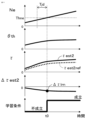
- FIG. 10 the internal combustion engine is in a state where there are no individual variations or aging changes, the second estimated torque ⁇ est2 and the reference value ⁇ est2ref of the second estimated torque match, and the deviation ⁇ est2 is close to zero.
- the throttle opening ⁇ th increases, the torque increases, and the rotational speed Ne increases continuously. While the rotational speed Ne is increasing, the rotational speed Ne passes the determination rotational speed Thne at time t01, and the learning condition is satisfied.
- the deviation ⁇ est2 when the learning condition is satisfied is learned as the error learning value ⁇ lrn.
- FIG. 11 the internal combustion engine is in a state where there are individual variations and changes over time, the second estimated torque ⁇ est2 exceeds the second estimated torque reference value ⁇ est2ref, and the deviation ⁇ est2 is smaller than zero.
- the throttle opening ⁇ th increases, the torque increases, and the rotational speed Ne increases continuously. While the rotational speed Ne is increasing, the rotational speed Ne passes the determination rotational speed Thne at time t01, and the learning condition is satisfied.
- the deviation ⁇ est2 when the learning condition is satisfied is learned as the error learning value ⁇ lrn.
- the average value of the deviation ⁇ est2 obtained multiple times when the learning condition is satisfied multiple times may be learned as the error learning value ⁇ lrn.
Abstract
内燃機関の個体差、経年変化により生じた内燃機関の出力トルクのばらつきを精度よく学習できる内燃機関のトルク推定装置を提供する。第1推定トルク用のトルク特性データを用い、第1推定トルク(τest1)を算出し、角加速度(αd)に基づいて、第2推定トルク(τest2)を算出し、第2推定トルク(τest2)と、予め設定された第2推定トルクの基準値(τest2ref)との偏差(Δτest2)を、誤差学習値(Δτlrn)として学習し、第1推定トルク(τest1)を誤差学習値(Δτlrn)により補正した値を、第3推定トルク(τest3)として算出する内燃機関のトルク推定装置(100)。
Description
本願は、内燃機関のトルク推定装置に関するものである。
特許文献1の技術では、出力トルクに影響する運転状態であるスロットル開度、吸入空気量、及び燃料噴射量などに基づいて、内燃機関のトルク特性を用い、内燃機関の出力トルクを推定している。また、特許文献1の技術では、トルクコンバータの特性に基づいて、内燃機関の出力トルクを推定し、トルク推定誤差を学習している。
特許文献1の技術では、内燃機関の個体差、経年変化により生じた出力トルクのばらつきを、内燃機関の外部の装置であるトルクコンバータの特性を利用して学習している。しかしながら、トルクコンバータの特性にもばらつきがあり、また、学習できる運転領域が限られる。
そこで、本願は、内燃機関の個体差、経年変化により生じた内燃機関の出力トルクのばらつきを精度よく学習できる内燃機関のトルク推定装置を提供することを目的とする。
本願に係る内燃機関のトルク推定装置は、
内燃機関のクランク軸の回転速度及び角加速度を検出する回転情報検出部と、
スロットル開度、筒内吸入空気量、燃料噴射量、及び前記回転速度の少なくとも1つ以上のトルク特性データ用の運転状態と、前記内燃機関の出力トルクとしての第1推定トルクとの関係が予め設定された第1推定トルク用のトルク特性データを用い、現在の前記トルク特性データ用の運転状態に対応する前記第1推定トルクを算出する第1推定トルク算出部と、
前記角加速度に基づいて、前記クランク軸のトルクの推定値である第2推定トルクを算出する第2推定トルク算出部と、
前記第2推定トルクと、予め設定された第2推定トルクの基準値との偏差を、誤差学習値として学習し、前記第1推定トルクを前記誤差学習値により補正した値を、第3推定トルクとして算出する第3推定トルク算出部と、を備えたものである。
本願に係る内燃機関のトルク推定装置によれば、実際に検出した角加速度に基づいて算出した第2推定トルクを、第2推定トルクの基準値と比較することにより、内燃機関の個体ばらつき、経年変化等により生じたトルクばらつきを、誤差学習値として学習することができる。そして、誤差学習値により、予め設定された基準状態のトルク特性データに基づいて算出された第1推定トルクを補正して、第3推定トルクを算出することで、内燃機関の個体ばらつき、経年変化等により生じたトルクばらつきが反映された、精度の良いトルク推定値を算出することができる。
1.実施の形態1
実施の形態1に係る内燃機関のトルク推定装置100(以下、単に、トルク推定装置100と称す)について図面を参照して説明する。図1は、本実施の形態に係る内燃機関1及びトルク推定装置100の概略構成図であり、図2は、本実施の形態に係るトルク推定装置100のブロック図である。本実施の形態では、トルク推定装置100は、内燃機関の制御装置50に組み込まれている。なお、トルク推定装置100は、内燃機関の制御装置50と別体であってもよい。
実施の形態1に係る内燃機関のトルク推定装置100(以下、単に、トルク推定装置100と称す)について図面を参照して説明する。図1は、本実施の形態に係る内燃機関1及びトルク推定装置100の概略構成図であり、図2は、本実施の形態に係るトルク推定装置100のブロック図である。本実施の形態では、トルク推定装置100は、内燃機関の制御装置50に組み込まれている。なお、トルク推定装置100は、内燃機関の制御装置50と別体であってもよい。
1-1.内燃機関1の構成
まず、内燃機関1の構成について説明する。図1に示すように、内燃機関1は、空気と燃料の混合気を燃焼する燃焼室7(以下、気筒7とも称す)を備えている。内燃機関1は、燃焼室7に空気を供給する吸気管23と、燃焼室7で燃焼した排気ガスを排出する排気管17とを備えている。内燃機関1は、ガソリンエンジンとされている。内燃機関1は、吸気管23を開閉するスロットルバルブ4を備えている。スロットルバルブ4は、制御装置50により制御される電気モータにより開閉駆動される電子制御式スロットルバルブとされている。スロットルバルブ4には、スロットルバルブ4の開度に応じた電気信号を出力するスロットル開度センサ19が設けられている。
まず、内燃機関1の構成について説明する。図1に示すように、内燃機関1は、空気と燃料の混合気を燃焼する燃焼室7(以下、気筒7とも称す)を備えている。内燃機関1は、燃焼室7に空気を供給する吸気管23と、燃焼室7で燃焼した排気ガスを排出する排気管17とを備えている。内燃機関1は、ガソリンエンジンとされている。内燃機関1は、吸気管23を開閉するスロットルバルブ4を備えている。スロットルバルブ4は、制御装置50により制御される電気モータにより開閉駆動される電子制御式スロットルバルブとされている。スロットルバルブ4には、スロットルバルブ4の開度に応じた電気信号を出力するスロットル開度センサ19が設けられている。
スロットルバルブ4の上流側の吸気管23には、吸気管23に吸入される吸入空気量に応じた電気信号を出力するエアフローセンサ3が設けられている。内燃機関1は、排気ガス還流装置20を備えている。排気ガス還流装置20は、排気管17から吸気マニホールド12に排気ガスを還流するEGR流路21と、EGR流路21を開閉するEGRバルブ22と、を有している。吸気マニホールド12は、スロットルバルブ4の下流側の吸気管23の部分である。EGRバルブ22は、制御装置50により制御される電気モータにより開閉駆動される電子制御式EGRバルブとされている。排気管17には、排気管17内の排気ガスの空燃比に応じた電気信号を出力する空燃比センサ18を備えている。
吸気マニホールド12には、吸気マニホールド12内の圧力に応じた電気信号を出力するガス圧センサ8が設けられている。吸気マニホールド12の下流側の部分には、燃料を噴射するインジェクタ13が設けられている。なお、インジェクタ13は、気筒7内に直接燃料を噴射するように設けられてもよい。内燃機関1には、大気圧に応じた電気信号を出力する大気圧センサ33が設けられている。内燃機関1には、冷却水温を検出する水温センサ34が設けられている。
燃焼室7の頂部には、空気と燃料の混合気に点火する点火プラグと、点火プラグに点火エネルギーを供給する点火コイル16と、が設けられている。また、燃焼室7の頂部には、吸気管23から燃焼室7内に吸入される吸入空気量を調節する吸気バルブ14と、燃焼室7内から排気管17に排出される排気ガス量を調節する排気バルブ15と、が設けられている。吸気バルブ14には、そのバルブ開閉タイミングを可変にする吸気可変バルブタイミング機構が設けられている。排気バルブ15には、そのバルブ開閉タイミングを可変にする排気可変バルブタイミング機構が設けられている。可変バルブタイミング機構14、15は、電動アクチュエータを有している。
内燃機関1は、複数の燃焼室7(本例では4つ)を備えている。各燃焼室7内には、ピストン5が備えられている。各燃焼室7のピストン5は、コンロッド9およびクランク32を介してクランク軸2に接続されている。クランク軸2は、ピストン5の往復運動によって回転駆動される。各燃焼室7で発生した燃焼ガス圧は、ピストン5の頂面を押圧し、コンロッド9およびクランク32を介してクランク軸2を回転駆動する。クランク軸2は、車輪、発電機等に駆動力を伝達する動力伝達機構に連結されている。動力伝達機構は、変速装置等から構成される。
内燃機関1は、クランク軸2と一体回転するロータ31を備えている。ロータ31は、予め定められた複数のクランク角度に複数の歯を設けている。本実施の形態では、ロータ31は、20度間隔で歯が並べられている。ロータ31の歯には、一部の歯が欠けた欠け歯部分が設けられている。内燃機関1は、エンジンブロック24に固定され、ロータ31の歯を検出するクランク角センサ11を備えている。
内燃機関1は、クランク軸とチェーンで連結されたカム軸を備えている。カム軸は、吸気バルブ14および排気バルブ15を開閉駆動する。クランク軸2が2回転する間に、カム軸は1回転する。内燃機関1は、カム軸と一体回転するカム用のロータを備えている。カム用のロータは、予め定められた複数のカム軸角度に複数の歯を設けている。内燃機関1は、エンジンブロック24に固定され、カム用のロータの歯を検出するカム角センサ30(図3参照)を備えている。
制御装置50は、クランク角センサ11およびカム角センサ30の2種類の出力信号に基づいて、各ピストン5の上死点(TDC)を基準としたクランク角度を検出すると共に、各燃焼室7の行程を判別する。なお、内燃機関1は、吸入行程、圧縮行程、燃焼行程、および排気行程の4行程機関とされている。
クランク角センサ11、及びカム角センサ30は、クランク軸2の回転による、各センサと歯の距離の変化に応じた電気信号を出力する。各角センサ11、30の出力信号は、センサと歯の距離が近い場合と、遠い場合とで信号がオンオフする矩形波となる。各角センサ11、30には、例えば、電磁ピックアップ式のセンサが用いられる。
なお、内燃機関の構成は、図1を用いて説明した構成に限定されず、各種の構成の内燃機関が用いられてもよい。
1-2.トルク推定装置100(制御装置50)の構成
次に、トルク推定装置100について説明する。トルク推定装置100は、内燃機関の制御装置50に組み込まれている。図2に示すように、制御装置50は、回転情報検出部51、第1推定トルク算出部52、第2推定トルク算出部53、及び第3推定トルク算出部54等の処理部を備えている。制御装置50の各処理部51から54等は、制御装置50が備えた処理回路により実現される。具体的には、制御装置50は、図3に示すように、処理回路として、CPU(Central Processing Unit)等の演算処理装置90(コンピュータ)、演算処理装置90にバス等の信号線を介して接続された記憶装置91、演算処理装置90に外部の信号を入力する入力回路92、および演算処理装置90から外部に信号を出力する出力回路93等を備えている。
次に、トルク推定装置100について説明する。トルク推定装置100は、内燃機関の制御装置50に組み込まれている。図2に示すように、制御装置50は、回転情報検出部51、第1推定トルク算出部52、第2推定トルク算出部53、及び第3推定トルク算出部54等の処理部を備えている。制御装置50の各処理部51から54等は、制御装置50が備えた処理回路により実現される。具体的には、制御装置50は、図3に示すように、処理回路として、CPU(Central Processing Unit)等の演算処理装置90(コンピュータ)、演算処理装置90にバス等の信号線を介して接続された記憶装置91、演算処理装置90に外部の信号を入力する入力回路92、および演算処理装置90から外部に信号を出力する出力回路93等を備えている。
演算処理装置90として、ASIC(Application Specific Integrated Circuit)、IC(Integrated Circuit)、DSP(Digital Signal Processor)、FPGA(Field Programmable Gate Array)、各種の論理回路、および各種の信号処理回路等が備えられてもよい。また、演算処理装置90として、同じ種類のもの又は異なる種類のものが複数備えられ、各処理が分担して実行されてもよい。
記憶装置91として、RAM(Random Access Memory)、ROM(Read Only Memory)、EEPROM(Electrically Erasable Programmable ROM)等の揮発性及び不揮発性の記憶装置が備えられている。入力回路92は、各種のセンサ及びスイッチが接続され、これらセンサ及びスイッチの出力信号を演算処理装置90に入力するA/D変換器等を備えている。出力回路93は、電気負荷が接続され、これら電気負荷に演算処理装置90から制御信号を出力する駆動回路等を備えている。
そして、制御装置50が備える各処理部51から54等の各機能は、演算処理装置90が、ROM、EEPROM等の記憶装置91に記憶されたソフトウェア(プログラム)を実行し、記憶装置91、入力回路92、および出力回路93等の制御装置50の他のハードウェアと協働することにより実現される。なお、各処理部51から54等が用いる第1推定トルク用のトルク特性データ、慣性モーメントIcrk、負荷トルクτload、基準値用のトルク特性データ等の設定データは、ROM、EEPROM等の記憶装置91に記憶されている。また、各処理部51から54等が算出した回転速度Ne、角速度ωd、角加速度αd、第1推定トルクτest1、角加速度の最大値αmax、第2推定トルクτest2、誤差学習値Δτlrn等の各算出値、及び各検出値等のデータは、RAM等の書き換え可能な記憶装置91に記憶される。
本実施の形態では、入力回路92には、クランク角センサ11、カム角センサ30、水温センサ34、エアフローセンサ3、スロットル開度センサ19、ガス圧センサ8、大気圧センサ33、空燃比センサ18、およびアクセルポジションセンサ26等が接続されている。出力回路93には、スロットルバルブ4(電気モータ)、EGRバルブ22(電気モータ)、インジェクタ13、点火コイル16、吸気可変バルブタイミング機構14、及び排気可変バルブタイミング機構15等が接続されている。なお、トルク推定装置100には、図示していない各種のセンサ、スイッチ、およびアクチュエータ等が接続されている。制御装置50は、各種センサの出力信号に基づいて、スロットル開度θth、筒内吸入空気量、吸気マニホールド内の圧力、大気圧、空燃比等の内燃機関1の運転状態を検出する。
制御装置50は、基本的な制御として、入力された各種センサの出力信号等に基づいて、燃料噴射量、点火時期等を算出し、インジェクタ13および点火コイル16等を駆動制御する。制御装置50は、アクセルポジションセンサ26の出力信号等に基づいて、運転者が要求している内燃機関1の出力トルクを算出し、当該要求出力トルクを実現する吸入空気量となるように、スロットルバルブ4等を制御する。具体的には、制御装置50は、目標スロットル開度を算出し、スロットル開度センサ19の出力信号に基づき検出したスロットル開度θthが、目標スロットル開度に近づくように、スロットルバルブ4の電気モータを駆動制御する。また、制御装置50は、入力された各種センサの出力信号等に基づいて、EGRバルブ22の目標開度を算出し、EGRバルブ22の電気モータを駆動制御する。制御装置50は、入力された各種センサの出力信号等に基づいて、吸気バルブの目標開閉タイミング及び排気バルブの目標開閉タイミングを算出し、各目標開閉タイミングに基づいて、吸気及び排気可変バルブタイミング機構14、15を駆動制御する。
1-2-1.回転情報検出部51
回転情報検出部51は、内燃機関のクランク軸の回転速度Ne及び角加速度αdを検出する。本実施の形態では、回転情報検出部51は、クランク角センサ11の出力信号に基づいて、クランク角度θdを検出し、検出したクランク角度θdの時間変化率である角速度ωd、及び角速度ωdの時間変化率である角加速度αdを算出する。回転情報検出部51は、クランク角センサ11の出力信号に基づいて、クランク軸の回転速度Neを検出する。なお、回転速度Neは、角速度ωdに対応するが、本実施の形態では、行程周期の平均的な速度である。
回転情報検出部51は、内燃機関のクランク軸の回転速度Ne及び角加速度αdを検出する。本実施の形態では、回転情報検出部51は、クランク角センサ11の出力信号に基づいて、クランク角度θdを検出し、検出したクランク角度θdの時間変化率である角速度ωd、及び角速度ωdの時間変化率である角加速度αdを算出する。回転情報検出部51は、クランク角センサ11の出力信号に基づいて、クランク軸の回転速度Neを検出する。なお、回転速度Neは、角速度ωdに対応するが、本実施の形態では、行程周期の平均的な速度である。
本実施の形態では、図4に示すように、回転情報検出部51は、クランク角センサ11の出力信号に基づいてクランク角度θdを検出すると共にクランク角度θdを検出した検出時刻Tdを検出する。そして、回転情報検出部51は、検出したクランク角度θdである検出角度θdおよび検出時刻Tdに基づいて、検出角度θdの間に対応する角度間隔Δθdおよび時間間隔ΔTdを算出する。
例えば、回転情報検出部51は、クランク角センサ11の出力信号(矩形波)の立下りエッジ(又は立上りエッジ)を検出した時のクランク角度θdを判定する。回転情報検出部51は、公知の方法を用い、クランク角センサ11およびカム角センサ30の2種類の出力信号に基づいて、第1気筒のピストンの上死点(TDC)を基準としたクランク角度θdを検出すると共に、各気筒7の行程を判別する。図5に、第1気筒から第4気筒の行程を示す。
<角速度ωd、角加速度αdの算出>
回転情報検出部51は、各クランク角度θd、及び各クランク角度θdを検出した検出時刻Tdに基づいて、角速度ωdを算出する。例えば、次式に示すように、回転情報検出部51は、今回検出したクランク角度θd(n)と前回検出したクランク角度θd(n-1)との角度間隔Δθd(n)と、今回の検出時刻Td(n)と前回の検出時刻Td(n-1)との時間間隔ΔTd(n)とに基づいて、今回の検出角度の角速度ωd(n)を算出する。なお、角速度ωdの算出について、これ以外にも、公知の各種の方法が用いられてもよい。

回転情報検出部51は、各クランク角度θd、及び各クランク角度θdを検出した検出時刻Tdに基づいて、角速度ωdを算出する。例えば、次式に示すように、回転情報検出部51は、今回検出したクランク角度θd(n)と前回検出したクランク角度θd(n-1)との角度間隔Δθd(n)と、今回の検出時刻Td(n)と前回の検出時刻Td(n-1)との時間間隔ΔTd(n)とに基づいて、今回の検出角度の角速度ωd(n)を算出する。なお、角速度ωdの算出について、これ以外にも、公知の各種の方法が用いられてもよい。
回転情報検出部51は、角速度ωdに基づいて、角加速度αdを算出する。例えば、次式に示すように、回転情報検出部51は、今回の検出角度で算出した角速度ωd(n)と前回の検出角度で算出した角速度ωd(n-1)と今回の検出角度の時間間隔ΔTd(n)とに基づいて、今回の検出角度の角加速度αd(n)を算出する。なお、角加速度αdの算出について、これ以外にも、公知の各種の方法が用いられてもよい。

1-2-2.第1推定トルク算出部52
第1推定トルク算出部52は、スロットル開度θth、筒内吸入空気量、燃料噴射量、及び回転速度Neの少なくとも1つ以上のトルク特性データ用の運転状態と、内燃機関の出力トルクとしての第1推定トルクτest1との関係が予め設定された第1推定トルク用のトルク特性データを用い、現在のトルク特性データ用の運転状態に対応する第1推定トルクτest1を算出する。第1推定トルクτest1は、クランク軸から内燃機関の外部に出力されるトルクであり、行程周期の間の平均的な出力トルクである。
第1推定トルク算出部52は、スロットル開度θth、筒内吸入空気量、燃料噴射量、及び回転速度Neの少なくとも1つ以上のトルク特性データ用の運転状態と、内燃機関の出力トルクとしての第1推定トルクτest1との関係が予め設定された第1推定トルク用のトルク特性データを用い、現在のトルク特性データ用の運転状態に対応する第1推定トルクτest1を算出する。第1推定トルクτest1は、クランク軸から内燃機関の外部に出力されるトルクであり、行程周期の間の平均的な出力トルクである。
例えば、トルク特性データ用の運転状態として、スロットル開度θth及び回転速度Neが用いられる場合を説明する。図6に示すように、第1推定トルク用のトルク特性データは、スロットル開度θth、回転速度Ne、第1推定トルクτest1との関係が予め設定されたマップデータとされる。第1推定トルク算出部52は、第1推定トルク用のトルク特性データを参照し、現在のスロットル開度θth及び回転速度Neに対応する第1推定トルクτest1を算出する。ここで、スロットル開度θthの代わりに、筒内吸入空気量、又は燃料噴射量が用いられてもよい。すなわち、トルク特性データ用の運転状態として、回転速度Ne、及び燃料噴射量に相関するパラメータが用いられるとよい。
なお、トルク特性データ用の運転状態として、出力トルクと相関する各種の内燃機関の運転状態、例えば、EGR率、点火時期、吸気バルブの開閉タイミング、排気バルブの開閉タイミングが用いられてもよい。なお、第1推定トルク用のトルク特性データは、複数のマップデータが組み合わされてもよく、又は、ニューラルネットワーク等が用いられてもよい。
1-2-3.第2推定トルク算出部53
第2推定トルク算出部53は、角加速度αdに基づいて、クランク軸のトルクの推定値である第2推定トルクτest2を算出する。
第2推定トルク算出部53は、角加速度αdに基づいて、クランク軸のトルクの推定値である第2推定トルクτest2を算出する。
本実施の形態では、図7に示すように、第2推定トルク算出部53は、燃焼行程の間の角加速度αdの最大値αmaxを算出し、角加速度の最大値αmaxに基づいて、第2推定トルクτest2を算出する。この構成によれば、燃焼行程の間の角加速度の最大値αmaxを算出することで、燃焼により増加した角加速度の最大値αmaxを用いて、第2推定トルクτest2を算出することができ、第2推定トルクτest2として、主に燃焼により増加した瞬時トルクの最大値を算出することができる。
本実施の形態では、内燃機関1は4つの燃焼室7(気筒7)を備えている。第2推定トルク算出部53は、4つの燃焼室7のそれぞれについて、燃焼行程の間の角加速度の最大値αmax1、αmax2、αmax3、αmax4を算出し、次式に示すように、4つの燃焼室の角加速度の最大値の平均値αmaxaveに基づいて、第2推定トルクτest2を算出する。平均値αmaxaveは、クランク軸が2回転する毎に算出される。

この構成によれば、気筒間に燃焼トルクのばらつきがあっても、気筒間の平均的な瞬時燃焼トルクの最大値を算出することができる。
第2推定トルク算出部53は、角加速度αd(本例では、角加速度の最大値の気筒間平均値αmaxave)に、慣性モーメントIcrkを乗算して、第2推定トルクτest2を算出する。慣性モーメントIcrkは、クランク軸と一体的に回転する各回転部材の慣性モーメントの合計値であり、予め設定されている。

本実施の形態では、第2推定トルク算出部53は、角加速度αdと慣性モーメントIcrkとの乗算値から、負荷トルクτloadを減算して、第2推定トルクτest2を算出する。負荷トルクτloadは、内燃機関の外部からクランク軸にかかる各種の負荷トルクであり、通常は負の値になる。例えば、負荷トルクτloadには、予め設定された値が用いられる。或いは、負荷トルクτloadは、通常、行程周期では大きく変動しないため、第2推定トルク算出部53は、ピストンの上死点(TDC)付近の角度の角加速度αdに慣性モーメントIcrkを乗算したトルクを、負荷トルクτloadとして用いてもよい。上死点(TDC)付近の角度は、上死点前10度から上死点後10度までの範囲内の角度、例えば、TDCに設定されるとよい。上死点近傍では、コンロッド及びクランクが一直線になり、筒内圧がピストンを押す力により、軸トルクが生じないため、負荷トルクτloadを算出できる。この構成によれば、内燃機関の外部からクランク軸にかかる負荷トルクτloadを除外することができ、燃焼により増加した瞬時トルクの増加量を算出することができ、第2推定トルクτest2の算出精度を高めることができる。
なお、行程周期の間の平均的な角加速度が、第2推定トルクτest2の算出に用いられてもよい。
1-2-4.第3推定トルク算出部54
第3推定トルク算出部54は、第2推定トルクτest2と、予め設定された第2推定トルクの基準値τest2refとの偏差Δτest2を、誤差学習値Δτlrnとして学習し、第1推定トルクτest1を誤差学習値Δτlrnにより補正した値を、第3推定トルクτest3として算出する。
第3推定トルク算出部54は、第2推定トルクτest2と、予め設定された第2推定トルクの基準値τest2refとの偏差Δτest2を、誤差学習値Δτlrnとして学習し、第1推定トルクτest1を誤差学習値Δτlrnにより補正した値を、第3推定トルクτest3として算出する。
この構成によれば、実際に検出した角加速度αdに基づいて算出した第2推定トルクτest2を、第2推定トルクの基準値τest2refと比較することにより、内燃機関1の個体ばらつき、経年変化等により生じたトルクばらつきを、誤差学習値Δτlrnとして学習することができる。そして、誤差学習値Δτlrnにより、予め設定された基準状態のトルク特性データに基づいて算出された第1推定トルクτest1を補正して、第3推定トルクτest3を算出することで、内燃機関1の個体ばらつき、経年変化等により生じたトルクばらつきが反映された、精度の良いトルク推定値を算出することができる。
なお、制御装置50は、第3推定トルクτest3に基づいて、内燃機関の出力トルクを制御するトルク制御を行う。例えば、制御装置50は、第3推定トルクτest3が、要求出力トルクに近づくように、目標スロットル開度を算出する。また、制御装置50は、第3推定トルクτest3を、車両制御装置、モータ制御装置などの外部の制御装置に伝達し、外部の制御装置のトルク制御に反映させる。
図2に示すように、第3推定トルク算出部54は、基準値算出部541、学習値算出部542、及び推定トルク補正部543を備えている。
<基準値算出部541>
基準値算出部541は、スロットル開度θth、筒内吸入空気量、燃料噴射量、及び回転速度Neの少なくとも1つ以上の基準値用の運転状態と、第2推定トルクの基準値τest2refとの関係が予め設定された基準値用のトルク特性データを用い、現在の基準値用の運転状態に対応する第2推定トルクの基準値τest2refを算出する。
基準値算出部541は、スロットル開度θth、筒内吸入空気量、燃料噴射量、及び回転速度Neの少なくとも1つ以上の基準値用の運転状態と、第2推定トルクの基準値τest2refとの関係が予め設定された基準値用のトルク特性データを用い、現在の基準値用の運転状態に対応する第2推定トルクの基準値τest2refを算出する。
本実施の形態では、第2推定トルクの基準値τest2refは、燃焼により増加した瞬時トルクの最大値又は増加量であるため、行程周期の間の平均的な出力トルクである第1推定トルクτest1とは異なる値になる。そのため、基準値用のトルク特性データは、第1推定トルク用のトルク特性データと異なる値が設定されている。
例えば、基準値用の運転状態として、スロットル開度θth及び回転速度Neが用いられる場合を説明する。図8に示すように、基準値用のトルク特性データは、スロットル開度θth、回転速度Ne、第2推定トルクの基準値τest2refとの関係が予め設定されたマップデータとされる。基準値算出部541は、基準値用のトルク特性データを参照し、現在のスロットル開度θth及び回転速度Neに対応する第2推定トルクの基準値τest2refを算出する。ここで、スロットル開度θthの代わりに、筒内吸入空気量、又は燃料噴射量が用いられてもよい。すなわち、基準値用の運転状態として、回転速度Ne、及び燃料噴射量に相関するパラメータが用いられるとよい。
なお、基準値用の運転状態として、出力トルクと相関する各種の内燃機関の運転状態、例えば、EGR率、点火時期、吸気バルブの開閉タイミング、排気バルブの開閉タイミングが用いられてもよい。なお、基準値用のトルク特性データは、複数のマップデータが組み合わされてもよく、又は、ニューラルネットワーク等が用いられてもよい。
<学習値算出部542>
学習値算出部542は、第2推定トルクτest2と第2推定トルクの基準値τest2refとの偏差Δτest2に基づいて、誤差学習値Δτlrnを更新する。
学習値算出部542は、第2推定トルクτest2と第2推定トルクの基準値τest2refとの偏差Δτest2に基づいて、誤差学習値Δτlrnを更新する。
学習値算出部542は、偏差Δτest2に対して統計処理を行って、誤差学習値Δτlrnを更新する。例えば、統計処理として、ローパスフィルタ処理が行われる。学習値算出部542は、次式を用いて、誤差学習値Δτlrnを更新する。ここで、(j)は、今回の更新周期の算出値を示し、(j-1)は、前回の更新周期の算出値を示し、Kfltは、フィルタゲインである。本実施の形態では、更新周期は、クランク軸が2回転する周期に設定される。

なお、スロットル開度θth、筒内吸入空気量、燃料噴射量、及び回転速度Neの少なくとも1つ以上の運転状態の領域ごとに、誤差学習値Δτlrnが設けられ、更新されてもよい。
<推定トルク補正部543>
推定トルク補正部543は、第1推定トルクτest1を誤差学習値Δτlrnにより補正した値を、第3推定トルクτest3として算出する。例えば、推定トルク補正部543は、次式を用いて、第3推定トルクτest3を算出する。

推定トルク補正部543は、第1推定トルクτest1を誤差学習値Δτlrnにより補正した値を、第3推定トルクτest3として算出する。例えば、推定トルク補正部543は、次式を用いて、第3推定トルクτest3を算出する。
或いは、推定トルク補正部543は、スロットル開度θth、筒内吸入空気量、燃料噴射量、及び回転速度Neの少なくとも1つ以上の補正係数用の運転状態に基づいて、補正係数Kτを算出し、次式に示すように、誤差学習値Δτlrnと補正係数Kτとの乗算値を、第1推定トルクτest1に加算した値を、第3推定トルクτest3として算出してもよい。

運転状態に応じて、推定トルクに対する誤差学習値Δτlrnの影響度合いが変化するため、誤差学習値Δτlrnに補正係数Kτを乗算することで、補正精度を向上させることができる。また、燃焼により増加した瞬時トルクの最大値又は増加量に対する、行程周期の間の平均的な出力トルクの比例係数は、運転状態に応じて変化するため、補正係数用の運転状態に基づいて補正係数Kτを算出し、誤差学習値Δτlrnに補正係数Kτを乗算することで、補正精度を向上させることができる。
推定トルク補正部543は、補正係数用の運転状態と補正係数Kτとの関係が予め設定された基準値用の補正係数設定データを用い、現在の補正係数用の運転状態に対応する補正係数Kτを算出する。補正係数設定データは、基準値用のトルク特性データ等と同様に構成される。
2.実施の形態2
実施の形態2に係るトルク推定装置100について図面を参照して説明する。上記の実施の形態1と同様の構成部分は説明を省略する。本実施の形態に係るトルク推定装置100の基本的な構成は実施の形態1と同様である。本実施の形態では、第3推定トルク算出部54の処理の一部が実施の形態1と異なる。
実施の形態2に係るトルク推定装置100について図面を参照して説明する。上記の実施の形態1と同様の構成部分は説明を省略する。本実施の形態に係るトルク推定装置100の基本的な構成は実施の形態1と同様である。本実施の形態では、第3推定トルク算出部54の処理の一部が実施の形態1と異なる。
本実施の形態では、図9に示すように、第3推定トルク算出部54は、第3推定トルク算出部54は、基準値算出部541、学習値算出部542、及び推定トルク補正部543に加えて、学習条件判定部544を備えている。
学習条件判定部544は、スロットル開度θth、筒内吸入空気量、燃料噴射量、及び回転速度Neの少なくとも1つ以上の学習判定用の運転状態に基づいて、学習条件が成立しているか否かを判定する。学習値算出部542は、学習条件が成立した場合に、偏差Δτest2に基づいて、誤差学習値Δτlrnを更新する。
この構成によれば、予め設定した学習条件が成立した場合に、学習を行うことにより、学習精度を向上させることができる。
本実施の形態では、図10及び図11に示すように、学習条件判定部544は、回転速度Neの増加中に、回転速度Neが、予め設定された判定回転速度Thneを通過したときに、学習条件が成立したと判定する。
回転速度Neの加速及び減速が行われている状態では、内燃機関のトルクが増減している過渡状態であるため、この過渡状態で学習を行うと、学習精度の低下を招きやすい。回転速度Neが連続して増加している状態では、トルクの増減が少なく、安定しているため、学習精度を向上できる。特に、2輪車両の場合は、4輪車両に比べ内燃機関の出力が小さく、低慣性であるため、変動要因により学習精度が低下し易いが、上記の構成により、学習精度の低下を抑制できる。
例えば、学習条件判定部544は、判定期間Tjdの間、連続して回転速度Neが増加しており、且つ、回転速度Neが、判定回転速度Thneを通過したときに、学習条件が成立したと判定する。
判定期間Tjdを設定することで、トルクの増減が少なく、安定している状態を、より精度よく判定でき、学習精度を向上できる。
更に、学習条件判定部544は、判定期間Tjdの間、連続して回転速度Neが、予め設定された増加率の範囲内で増加しており、且つ、回転速度Neが、判定回転速度Thneを通過したときに、学習条件が成立したと判定してもよい。
回転速度Neの増加率の範囲を設定することで、トルクの増減が少なく、安定している状態を、更に精度よく判定でき、学習精度を向上できる。
図10及び図11を用いて、学習時の挙動を説明する。まず、図10について説明する。図10では、内燃機関に個体ばらつき及び経年変化が無い状態であり、第2推定トルクτest2と第2推定トルクの基準値τest2refとが一致しており、偏差Δτest2がゼロに近い。スロットル開度θthが増加し、トルクが増加し、回転速度Neが連続的に増加している。回転速度Neの増加中に、時刻t01で、回転速度Neが判定回転速度Thneを通過しており、学習条件が成立している。学習条件が成立したときの偏差Δτest2が誤差学習値Δτlrnとして学習される。
次に、図11について説明する。図11では、内燃機関に個体ばらつき及び経年変化が有る状態であり、第2推定トルクτest2が第2推定トルクの基準値τest2refを上回っており、偏差Δτest2がゼロよりも小さくなっている。スロットル開度θthが増加し、トルクが増加し、回転速度Neが連続的に増加している。回転速度Neの増加中に、時刻t01で、回転速度Neが判定回転速度Thneを通過しており、学習条件が成立している。学習条件が成立したときの偏差Δτest2が誤差学習値Δτlrnとして学習される。
なお、学習条件が複数回成立したときの複数回の偏差Δτest2の平均値が、誤差学習値Δτlrnとして学習されてもよい。
上記の各実施の形態においては、気筒数が4つの4気筒の内燃機関が用いられる場合を例に説明した。しかし、任意の気筒数(例えば、1気筒、2気筒、3気筒、6気筒)の内燃機関が用いられてもよい。
本願は、様々な例示的な実施の形態及び実施例が記載されているが、1つ、または複数の実施の形態に記載された様々な特徴、態様、及び機能は特定の実施の形態の適用に限られるのではなく、単独で、または様々な組み合わせで実施の形態に適用可能である。従って、例示されていない無数の変形例が、本願明細書に開示される技術の範囲内において想定される。例えば、少なくとも1つの構成要素を変形する場合、追加する場合または省略する場合、さらには、少なくとも1つの構成要素を抽出し、他の実施の形態の構成要素と組み合わせる場合が含まれるものとする。
1 内燃機関、2 クランク軸、7 燃焼室(気筒)、51 回転情報検出部、52 第1推定トルク算出部、53 第2推定トルク算出部、54 第3推定トルク算出部、100 トルク推定装置、Kτ 補正係数、Ne 回転速度、Thne 判定回転速度、Tjd 判定期間、τest1 第1推定トルク、τest2 第2推定トルク、τest2ref 第2推定トルクの基準値、τest3 第3推定トルク、Δτest2 偏差、Δτlrn 誤差学習値、αd 角加速度、αmax 角加速度の最大値、θth スロットル開度
Claims (8)
- 内燃機関のクランク軸の回転速度及び角加速度を検出する回転情報検出部と、
スロットル開度、筒内吸入空気量、燃料噴射量、及び前記回転速度の少なくとも1つ以上のトルク特性データ用の運転状態と、前記内燃機関の出力トルクとしての第1推定トルクとの関係が予め設定された第1推定トルク用のトルク特性データを用い、現在の前記トルク特性データ用の運転状態に対応する前記第1推定トルクを算出する第1推定トルク算出部と、
前記角加速度に基づいて、前記クランク軸のトルクの推定値である第2推定トルクを算出する第2推定トルク算出部と、
前記第2推定トルクと、予め設定された第2推定トルクの基準値との偏差を、誤差学習値として学習し、前記第1推定トルクを前記誤差学習値により補正した値を、第3推定トルクとして算出する第3推定トルク算出部と、を備えた内燃機関のトルク推定装置。 - 前記第3推定トルク算出部は、前記スロットル開度、前記筒内吸入空気量、前記燃料噴射量、及び前記回転速度の少なくとも1つ以上の学習判定用の運転状態に基づいて、学習条件が成立しているか否かを判定し、前記学習条件が成立したと判定した場合に、前記偏差に基づいて、前記誤差学習値を更新する請求項1に記載の内燃機関のトルク推定装置。
- 前記第3推定トルク算出部は、前記スロットル開度、前記筒内吸入空気量、前記燃料噴射量、及び前記回転速度の少なくとも1つ以上の補正係数用の運転状態に基づいて、補正係数を算出し、前記誤差学習値と前記補正係数との乗算値により、前記第1推定トルクを補正した値を、前記第3推定トルクとして算出する請求項1又は2に記載の内燃機関のトルク推定装置。
- 前記第2推定トルク算出部は、燃焼行程の間の前記角加速度の最大値を算出し、前記最大値に基づいて、前記第2推定トルクを算出する請求項1から3のいずれか一項に記載の内燃機関のトルク推定装置。
- 前記内燃機関は複数の燃焼室を備え、
前記第2推定トルク算出部は、前記複数の燃焼室のそれぞれについて、燃焼行程の間の前記角加速度の最大値を算出し、前記複数の燃焼室の前記最大値の平均値に基づいて、前記第2推定トルクを算出する請求項1から4のいずれか一項に記載の内燃機関のトルク推定装置。 - 前記第3推定トルク算出部は、前記スロットル開度、前記筒内吸入空気量、前記燃料噴射量、及び前記回転速度の少なくとも1つ以上の基準値用の運転状態と、前記第2推定トルクの基準値との関係が予め設定された基準値用のトルク特性データを用い、現在の前記基準値用の運転状態に対応する前記第2推定トルクの基準値を算出する請求項1から5のいずれか一項に記載の内燃機関のトルク推定装置。
- 前記第3推定トルク算出部は、前記回転速度の増加中に、前記回転速度が、予め設定された判定回転速度を通過したときに、学習条件が成立したと判定し、前記偏差に基づいて、前記誤差学習値を更新する請求項1から6のいずれか一項に記載の内燃機関のトルク推定装置。
- 前記第3推定トルク算出部は、判定期間の間、連続して前記回転速度が増加しており、且つ、前記回転速度が、前記判定回転速度を通過したときに、学習条件が成立したと判定する請求項7に記載の内燃機関のトルク推定装置。
Priority Applications (1)
| Application Number | Priority Date | Filing Date | Title |
|---|---|---|---|
| PCT/JP2022/024115 WO2023243035A1 (ja) | 2022-06-16 | 2022-06-16 | 内燃機関のトルク推定装置 |
Applications Claiming Priority (1)
| Application Number | Priority Date | Filing Date | Title |
|---|---|---|---|
| PCT/JP2022/024115 WO2023243035A1 (ja) | 2022-06-16 | 2022-06-16 | 内燃機関のトルク推定装置 |
Publications (1)
| Publication Number | Publication Date |
|---|---|
| WO2023243035A1 true WO2023243035A1 (ja) | 2023-12-21 |
Family
ID=89192501
Family Applications (1)
| Application Number | Title | Priority Date | Filing Date |
|---|---|---|---|
| PCT/JP2022/024115 WO2023243035A1 (ja) | 2022-06-16 | 2022-06-16 | 内燃機関のトルク推定装置 |
Country Status (1)
| Country | Link |
|---|---|
| WO (1) | WO2023243035A1 (ja) |
Citations (4)
| Publication number | Priority date | Publication date | Assignee | Title |
|---|---|---|---|---|
| JP2005016425A (ja) * | 2003-06-26 | 2005-01-20 | Mitsubishi Motors Corp | アイドル運転時空気量制御装置及びアイドル運転時空気量制御方法 |
| JP2006183506A (ja) * | 2004-12-27 | 2006-07-13 | Hitachi Ltd | エンジンの制御装置 |
| JP2009275618A (ja) * | 2008-05-15 | 2009-11-26 | Mitsubishi Electric Corp | 角速度及び角加速度算出装置、トルク推定装置、燃焼状態推定装置 |
| JP2017106393A (ja) * | 2015-12-10 | 2017-06-15 | 富士通株式会社 | 推定装置、推定方法、推定プログラム、エンジンシステム、および移動装置 |
-
2022
- 2022-06-16 WO PCT/JP2022/024115 patent/WO2023243035A1/ja unknown
Patent Citations (4)
| Publication number | Priority date | Publication date | Assignee | Title |
|---|---|---|---|---|
| JP2005016425A (ja) * | 2003-06-26 | 2005-01-20 | Mitsubishi Motors Corp | アイドル運転時空気量制御装置及びアイドル運転時空気量制御方法 |
| JP2006183506A (ja) * | 2004-12-27 | 2006-07-13 | Hitachi Ltd | エンジンの制御装置 |
| JP2009275618A (ja) * | 2008-05-15 | 2009-11-26 | Mitsubishi Electric Corp | 角速度及び角加速度算出装置、トルク推定装置、燃焼状態推定装置 |
| JP2017106393A (ja) * | 2015-12-10 | 2017-06-15 | 富士通株式会社 | 推定装置、推定方法、推定プログラム、エンジンシステム、および移動装置 |
Similar Documents
| Publication | Publication Date | Title |
|---|---|---|
| CN109899160B (zh) | 内燃机的控制装置及控制方法 | |
| CN107869401B (zh) | 内燃机的控制装置及其控制方法 | |
| CN107269409B (zh) | 内燃机的控制装置及其控制方法 | |
| CN106988919B (zh) | 内燃机的控制装置及其控制方法 | |
| US11480121B2 (en) | Controller and control method for internal combustion engine | |
| JP5944249B2 (ja) | 内燃機関の内部egr量算出装置 | |
| CN102758699B (zh) | 气缸压力参数校正系统和方法 | |
| US11555462B2 (en) | Controller and control method for internal combustion engine | |
| US6564785B2 (en) | Cylinder intake-air quantity calculating apparatus and method for internal combustion engine | |
| JP7030884B2 (ja) | 内燃機関の制御装置 | |
| US8818689B2 (en) | Cylinder intake air amount calculating apparatus for internal combustion engine | |
| US11703418B2 (en) | Controller for internal combustion engine | |
| WO2023243035A1 (ja) | 内燃機関のトルク推定装置 | |
| US20170114728A1 (en) | Control apparatus for internal combustion engine | |
| US11473517B1 (en) | Controller and control method for internal combustion engine | |
| JP2006207538A (ja) | 内燃機関の点火時期制御装置 | |
| WO2023199532A1 (ja) | 内燃機関の制御装置 | |
| US11686266B2 (en) | Controller for internal combustion engine | |
| US20230184187A1 (en) | Controller for internal combustion engine | |
| US20230184186A1 (en) | Controller for internal combustion engine | |
| JP6910512B1 (ja) | 内燃機関の制御装置 | |
| JP7246548B1 (ja) | 内燃機関の制御装置 |
Legal Events
| Date | Code | Title | Description |
|---|---|---|---|
| 121 | Ep: the epo has been informed by wipo that ep was designated in this application |
Ref document number: 22946852 Country of ref document: EP Kind code of ref document: A1 |