WO2023238829A1 - 水素化ホウ素化合物製造装置及び水素化ホウ素化合物の製造方法 - Google Patents
水素化ホウ素化合物製造装置及び水素化ホウ素化合物の製造方法 Download PDFInfo
- Publication number
- WO2023238829A1 WO2023238829A1 PCT/JP2023/020884 JP2023020884W WO2023238829A1 WO 2023238829 A1 WO2023238829 A1 WO 2023238829A1 JP 2023020884 W JP2023020884 W JP 2023020884W WO 2023238829 A1 WO2023238829 A1 WO 2023238829A1
- Authority
- WO
- WIPO (PCT)
- Prior art keywords
- compound
- stirring
- stirring tank
- boric acid
- borohydride
- Prior art date
- Legal status (The legal status is an assumption and is not a legal conclusion. Google has not performed a legal analysis and makes no representation as to the accuracy of the status listed.)
- Ceased
Links
Images


Classifications
-
- B—PERFORMING OPERATIONS; TRANSPORTING
- B01—PHYSICAL OR CHEMICAL PROCESSES OR APPARATUS IN GENERAL
- B01F—MIXING, e.g. DISSOLVING, EMULSIFYING OR DISPERSING
- B01F29/00—Mixers with rotating receptacles
- B01F29/60—Mixers with rotating receptacles rotating about a horizontal or inclined axis, e.g. drum mixers
- B01F29/64—Mixers with rotating receptacles rotating about a horizontal or inclined axis, e.g. drum mixers with stirring devices moving in relation to the receptacle, e.g. rotating
-
- B—PERFORMING OPERATIONS; TRANSPORTING
- B01—PHYSICAL OR CHEMICAL PROCESSES OR APPARATUS IN GENERAL
- B01F—MIXING, e.g. DISSOLVING, EMULSIFYING OR DISPERSING
- B01F31/00—Mixers with shaking, oscillating, or vibrating mechanisms
-
- B—PERFORMING OPERATIONS; TRANSPORTING
- B01—PHYSICAL OR CHEMICAL PROCESSES OR APPARATUS IN GENERAL
- B01F—MIXING, e.g. DISSOLVING, EMULSIFYING OR DISPERSING
- B01F35/00—Accessories for mixers; Auxiliary operations or auxiliary devices; Parts or details of general application
- B01F35/10—Maintenance of mixers
- B01F35/12—Maintenance of mixers using mechanical means
-
- C—CHEMISTRY; METALLURGY
- C01—INORGANIC CHEMISTRY
- C01B—NON-METALLIC ELEMENTS; COMPOUNDS THEREOF; METALLOIDS OR COMPOUNDS THEREOF NOT COVERED BY SUBCLASS C01C
- C01B6/00—Hydrides of metals including fully or partially hydrided metals, alloys or intermetallic compounds ; Compounds containing at least one metal-hydrogen bond, e.g. (GeH3)2S, SiH GeH; Monoborane or diborane; Addition complexes thereof
- C01B6/06—Hydrides of aluminium, gallium, indium, thallium, germanium, tin, lead, arsenic, antimony, bismuth or polonium; Monoborane; Diborane; Addition complexes thereof
- C01B6/10—Monoborane; Diborane; Addition complexes thereof
- C01B6/13—Addition complexes of monoborane or diborane, e.g. with phosphine, arsine or hydrazine
- C01B6/15—Metal borohydrides; Addition complexes thereof
- C01B6/19—Preparation from other compounds of boron
- C01B6/21—Preparation of borohydrides of alkali metals, alkaline earth metals, magnesium or beryllium; Addition complexes thereof, e.g. LiBH4.2N2H4, NaB2H7
Definitions
- the present invention relates to an apparatus for producing a borohydride compound and a method for producing a borohydride compound.
- boron hydride compounds such as sodium borohydride (NaBH 4 ) easily undergo a hydrolysis reaction with water to produce hydrogen and metaboric acid compounds, so their use as materials for storing hydrogen is being considered. .
- NaBH 4 sodium borohydride
- the borohydride compound is also used as a reducing agent and the like.
- Patent Document 1 describes a method for producing sodium borohydride (NaBH 4 ) by bringing sodium metaborate (NaBO 2 ) into contact with hydrogen gas.
- An object of the present invention is to provide an apparatus that can efficiently produce borohydride compounds.
- the above objectives are: [1] M ⁇ B ⁇ O ⁇ (M is an alkali metal atom or alkaline earth metal atom, ⁇ is an integer of 1 to 4, ⁇ is an integer of 1 to 8, ⁇ is an integer from 1 to 13, and ⁇ , ⁇ , and ⁇ may be the same or different.)
- a hydrogen gas supply means for supplying hydrogen gas
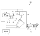
- FIG. 1 is a schematic diagram showing the configuration of a borohydride compound manufacturing apparatus according to an embodiment of the present invention.
- FIG. 2 is a schematic diagram for explaining the structure of a borohydride compound generating section according to an embodiment of the present invention.
- FIG. 2 is a schematic diagram for explaining the exhaust mechanism of the borohydride compound manufacturing apparatus according to the embodiment of the present invention.
- FIG. 1 is a schematic diagram showing the configuration of a borohydride compound manufacturing apparatus according to an embodiment of the present invention.
- a borohydride compound manufacturing apparatus 100 includes a borohydride compound production section 1, a control section 2, a vacuum pump section 3, a hydrogen gas supply section 4, a pressure gauge 5, (5a, 5b, and 5c), a hygrometer 6, and a valve 7 (7a, and 7b).
- the borohydride compound generating unit 1 is composed of M ⁇ B ⁇ O ⁇ (M is an alkali metal atom or an alkaline earth metal atom, ⁇ is an integer of 1 to 4, and ⁇ is an integer of 1 to 8). is an integer of 1 to 13, ⁇ is an integer of 1 to 13, and ⁇ , ⁇ , and ⁇ may be the same or different.) and hydrogen.
- a boron hydride compound is generated from hydrogen gas supplied from the gas supply section 4.
- the boric acid compound is sodium metaborate (NaBO 2 )
- the sodium metaborate (NaBO 2 ) reacts with hydrogen gas (H 2 ) as shown in the chemical reaction formula (1) below, and the boron hydride compound
- H 2 hydrogen gas
- sodium borohydride (NaBH 4 ) is produced. NaBO 2 +4H 2 ⁇ NaBH 4 +2H 2 O...(1)
- the boric acid compound is M ⁇ B ⁇ O ⁇ (M is an alkali metal atom or an alkaline earth metal atom, ⁇ is an integer of 1 to 4, and ⁇ is an integer of 1 to 8). ⁇ is an integer from 1 to 13, and ⁇ , ⁇ , and ⁇ may be the same or different.)
- borohydride By reacting with hydrogen gas, borohydride It is not particularly limited as long as it produces a compound.
- boric acid compounds include sodium metaborate (NaBO 2 ), sodium tetraborate (Na 2 B 4 O 7 ), sodium diborate (Na 4 B 2 O 5 ), and sodium octaborate (Na 2 B 8 O 13 ), sodium pentaborate (NaB 5 O 8 ), lithium metaborate (LiBO 2 ), lithium tetraborate (Li 2 B 4 O 7 ), potassium metaborate (KBO 2 ), potassium tetraborate (K 2 B 4 O 7 ), calcium metaborate (Ca(BO 2 ) 2 ), calcium tetraborate (CaB 4 O 7 ), and the like.
- the reaction shown in the chemical reaction formula (1) above is a reversible reaction, and when a boron hydride compound reacts with water, hydrogen and a metaboric acid compound are generated. Therefore, when a metaboric acid compound is used as the boric acid compound, the boron hydride compound can be generated again using the metaboric acid compound produced after hydrogen is removed from the boron hydride compound as a raw material. Therefore, from the viewpoint of resource recycling, the boric acid compound is preferably a metaboric acid compound.
- the boric acid compound may be a hydrate or an anhydride.
- water molecules contained in the boric acid compound may be removed to form an anhydride, and then the boric acid compound may be reacted with hydrogen gas.
- the method for removing water molecules contained in the boric acid compound is not particularly limited. For example, water molecules may be removed by heating the boric acid compound, or water molecules may be removed by drying the boric acid compound.
- a catalyst when a boric acid compound is reacted with hydrogen, a catalyst may or may not be used. When a catalyst is used when a boric acid compound is reacted with hydrogen, the catalyst may be removed from the boron hydride compound after the boron hydride compound is generated.
- the boron hydride compound is not particularly limited as long as it is generated from a boric acid compound and hydrogen gas.
- Examples of the borohydride compound include sodium borohydride (NaBH 4 ), potassium borohydride (KBH 4 ), lithium borohydride (LiBH 4 ), and calcium borohydride (Ca(BH 4 ) 2 ). It's fine.
- FIG. 2 is a schematic diagram for explaining the structure of the borohydride compound generating section according to the embodiment of the present invention.
- the borohydride compound generating section 1 according to the embodiment of the present invention includes a stirring tank 11, a stirring rod 12, a stirring control section 13 (13a and 13b), a heater 14, and a motor 15. We are prepared.
- the stirring tank 11 is for stirring the boric acid compound present inside the stirring tank 11.
- the mode for stirring is not particularly limited, as long as the boric acid compound can be stirred.
- “stirring” does not only mean stirring the material using a rod-shaped, plate-shaped, or propeller-shaped stirrer, but also stirring the material without using a rod-shaped, plate-shaped, or propeller-shaped stirrer. Changing the ingredients also includes stirring.
- the boric acid compound may be stirred by the stirring tank 11 rotating, or the boric acid compound may be stirred by the stirring tank 11 vibrating. Stirring the boric acid compound makes it easier for the boric acid compound and hydrogen gas to come into contact with each other, thereby increasing the reaction rate.
- the material, shape, and size of the stirring tank 11 are not particularly limited as long as the boric acid compound can be accommodated and stirred inside the stirring tank 11.
- a material for the stirring tank 11 for example, corrosion-resistant stainless steel, platinum, carbon, quartz, etc. can be used.
- the shape of the stirring tank 11, for example, a truncated cone shape, a cylindrical shape, a round-bottomed cylindrical shape, a pointed-bottomed cylindrical shape, a hemispherical shape, a spherical shape, etc. can be adopted.
- a heat-resistant crucible or a cylindrical drum may be used as the stirring tank 11.
- a large crucible is used, about 2 to 3 tons of boric acid compound can be contained. Further, when a drum is used, a larger amount of boric acid compound can be accommodated than a crucible.
- a heater 14 is provided outside the stirring tank 11 so as to accommodate the stirring tank 11.
- the heater 14 is controlled by the control unit 2 to heat the stirring tank 11 .
- the heater 14 can raise the temperature inside the boric acid compound or boron hydride compound producing section 1 by heating the stirring tank 11 .
- the temperature inside the boric acid compound or boron hydride compound generating section 1 the reaction rate between the boric acid compound and hydrogen gas can be increased.
- water molecules contained in the boric acid compound can be removed when the boric acid compound is a hydrate.
- the temperature of the stirring tank 11 heated by the heater 14 is preferably 100°C or higher, more preferably 150°C or higher, and even more preferably 180°C or higher. Further, the temperature of the stirring tank 11 heated by the heater 14 is preferably 500°C or lower, more preferably 400°C or lower, and even more preferably 300°C or lower.
- a motor 15 for transmitting power to the heater 14 and the stirring tank 11 is provided at the bottom of the heater 14.
- the motor 15 is controlled by the control unit 2 to transmit power to the heater 14 and the stirring tank 11.
- the motor 15 can stir the boric acid compound by transmitting power to the heater 14 and the stirring tank 11.
- the motor 15 may stir the boric acid compound by rotating the heater 14 and the stirring tank 11, or may stir the boric acid compound by vibrating the heater 14 and the stirring tank 11.
- the rotation speed of the stirring tank 11 is preferably 1 rpm or more, more preferably 5 rpm or more, and more preferably 10 rpm or more. It is even more preferable that there be.
- the rotational speed of the stirring tank 11 is within the above range, the boric acid compound can be efficiently stirred, and the reaction rate between the boric acid compound and hydrogen gas can be maintained at a suitable level.
- the top surface of the motor 15 is not parallel to the bottom surface of the borohydride compound generating section 1, but is inclined. Therefore, the central axis of the heater 14 installed on the upper surface of the motor 15 and the stirring tank 11 is inclined with respect to the direction of gravity. By installing the stirring tank 11 so that its central axis is inclined with respect to the direction of gravity, the boric acid compound can be efficiently stirred.
- the angle of inclination of the central axis of the stirring tank 11 with respect to the direction of gravity is preferably 30° or more, more preferably 40° or more, and even more preferably 45° or more. Further, the angle of inclination of the central axis of the stirring tank 11 with respect to the direction of gravity is preferably 60° or less, more preferably 55° or less, and even more preferably 50° or less.
- the base used when installing the stirring tank 11 inside the boron hydride compound generating section 1 must be The upper surface may have a structure inclined with respect to the bottom surface of the borohydride compound generating section 1.
- the top surface of the base used when installing the stirring tank 11 inside the boron hydride compound generation section 1 is movable, and is moved so as to be inclined with respect to the bottom surface of the boron hydride compound generation section 1 and then fixed. It may be possible.
- a stirring rod 12 that further stirs the boric acid compound by rotating is provided inside the stirring tank 11.
- the stirring bar 12 is controlled to rotate by stirring control units 13a and 13b installed at the top of the stirring bar 12. Further, the stirring controllers 13a and 13b are controlled by the controller 2.
- the stirring rod 12 may stir the boric acid compound by rotating around the central axis of the stirring rod 12 while being installed at the same position inside the stirring tank 11.
- the boric acid compound may be stirred by rotating the stirring rod 12 itself around the central axis of the stirring tank 11.
- the stirring rod 12 itself may be rotated around the central axis of the stirring tank 11, and further rotated around the central axis of the stirring rod 12 to stir the boric acid compound.
- the rotational speed of the stirring rod 12 when the stirring rod 12 rotates around the central axis of the stirring rod 12 is preferably 50 rpm or more, more preferably 100 rpm or more, and even more preferably 150 rpm or more. . Further, the rotation speed of the stirring rod 12 when the stirring rod 12 rotates around the central axis of the stirring rod 12 is preferably 300 rpm or less, more preferably 250 rpm or less, and preferably 200 rpm or less. More preferred. When the rotational speed of the stirring rod 12 is within the above range, the boric acid compound can be efficiently stirred, and the reaction rate between the boric acid compound and hydrogen gas can be maintained at a suitable level.
- the stirring rod 12 is movable at two locations indicated by broken line arrows 16a and 16b in the figure, and can be taken out of the stirring tank 11.
- the stirring rod 12 that rotates to further stir the boric acid compound is provided inside the stirring tank 11, so that the boric acid compound can be efficiently stirred.
- the directions in which the stirring tank 11 and the stirring rod 12 rotate are opposite to each other. That is, as shown in FIG. 2, when the stirring tank 11 rotates to the right in side view as shown by arrow 17a, stirring bar 12 rotates to the left in side view as shown by arrow 17b. is preferred.
- the boric acid compound can be efficiently stirred.
- the stirring rod 12 is approximately parallel to the central axis of the stirring tank 11.
- the stirring rod 12 may be substantially parallel to the inner wall of the stirring tank 11.
- the shape of the stirring rod 12 is not particularly limited, as long as it can stir the boric acid compound.
- the stirring rod 12 may be provided with a stirring blade or may not be provided with a stirring blade.
- the type of stirring blades is not particularly limited and can be designed as appropriate.
- the type of stirring blade may be, for example, an anchor type, screw type, helical ribbon type, paddle type, propeller type, Bernoulli type, or the like. In order to obtain sufficient stirring ability even when the boric acid compound contains water and becomes highly viscous, it is preferable to use an anchor type, screw type, helical ribbon type, or the like.
- the stirring rod 12 may be equipped with a peeling means for peeling off the boric acid compound adhering to the inner side surface of the stirring tank 11.
- the peeling means is not particularly limited as long as it can peel off the boric acid compound adhering to the inner side surface of the stirring tank 11, and can be designed as appropriate.
- a brush or a spatula can be used as the peeling means.
- the stirring tank 11 may be provided with a separate peeling means.
- the stirring blade may also function as a peeling means.
- the boron hydride compound manufacturing apparatus 100 By providing the boron hydride compound manufacturing apparatus 100 with a peeling means for peeling off the boric acid compound adhering to the inner side surface of the stirring tank 11, even if the boric acid compound adheres to the inner side surface of the stirring tank 11, it can be removed. , boric acid compounds can be efficiently stirred.
- the stirring rod 12 is arranged near the side surface inside the stirring tank 11. By disposing the stirring rod 12 near the side surface inside the stirring tank 11, even when the boric acid compound contains water and becomes highly viscous, the load on the stirring rod 12 can be reduced. .
- the stirring rod 12 is equipped with a peeling means for peeling off the boric acid compound adhering to the inner side surface of the stirring tank 11, the stirring rod 12 is placed near the inner side surface of the stirring tank 11. By doing so, the distance between the inner wall of the stirring tank 11 and the stirring rod 12 becomes closer, making it easier to peel off the boric acid compound.
- the vicinity of the inner side surface of the stirring tank 11 is, for example, a distance of (1/2) x r from the inner side surface of the stirring tank 11 in the direction perpendicular to the side surface, where r is the inner diameter of the stirring tank 11. It may be within a distance of (1/4) x r from the side of the inside of the stirring tank 11 in the direction perpendicular to the side, or from the side of the inside of the stirring tank 11 to the side. It may be within a distance of (1/6) x r in the direction perpendicular to the stirring tank 11, or it may be within a distance of (1/8) x r from the side of the inside of the stirring tank 11 in the direction perpendicular to the side. good.
- the borohydride compound generating section 1 may be equipped with a pressure gauge 5a.
- the pressure inside the borohydride compound generating section 1 can be measured by the pressure gauge 5a.
- the numerical value of the internal pressure of the boron hydride compound generating section 1 measured by the pressure gauge 5a may be transmitted to the control section 2.
- the control unit 2 can control the operation of the vacuum pump unit 3 and the hydrogen gas supply unit 4 based on the numerical value of the internal pressure of the boron hydride compound generation unit 1.
- the vacuum pump section 3 discharges the gas inside the boron hydride compound generating section 1 and brings the inside of the boron hydride compound generating section 1 into a vacuum or near-vacuum state.
- the vacuum pump section 3 is connected to the borohydride compound generating section 1 through a pipe or the like. Further, a pipe connecting the boron hydride compound generating section 1 and the vacuum pump section 3 is equipped with a valve 7a, a pressure gauge 5b, and a hygrometer 6.
- the vacuum pump section 3 and the valve 7a can be controlled by the control section 2.
- the valve 7a may be anything that can open and close the pipe, and may be an electromagnetic valve, an electric valve, or the like.
- control unit 2 can control the operation of the vacuum pump unit 3 based on the pressure value on the vacuum pump unit 3 side and the humidity value on the vacuum pump unit 3 side.
- the vacuum pump section 3 is not particularly limited as long as it can exhaust the gas inside the borohydride compound generating section 1 and make the inside of the borohydride compound generating section 1 a vacuum.
- the vacuum pump section 3 may have a structure in which a plurality of pumps are combined.
- the vacuum pump section 3 may have a structure that combines a main pump capable of evacuation to vacuum and an auxiliary pump that evacuation from atmospheric pressure to a pressure at which the main pump can operate.
- the boron hydride compound generating section 1 preferably has a highly airtight structure so that it can be brought into a vacuum or near-vacuum state by the vacuum pump section 3.
- the vacuum pump section 3 can discharge water vapor generated by heating the boric acid compound from the boron hydride compound generating section 1.
- the hydrogen gas supply section 4 supplies hydrogen gas into the boron hydride compound generation section 1.
- the borohydride compound generating section 1 and the hydrogen gas supply section 4 are connected by a pipe or the like. Further, a pipe connecting the boron hydride compound generating section 1 and the hydrogen gas supply section 4 is equipped with a valve 7b and a pressure gauge 5c.
- the hydrogen gas supply section 4 and the valve 7b can be controlled by the control section 2.
- the valve 7b may be anything that can open and close the pipe, and may be an electromagnetic valve, an electric valve, or the like.
- the numerical value of the pressure on the hydrogen gas supply section 4 side measured by the pressure gauge 5c may be transmitted to the control section 2.
- the control unit 2 can control the operation of the hydrogen gas supply unit 4 based on the numerical value of the pressure on the hydrogen gas supply unit 4 side.
- the hydrogen gas supply section 4 is not particularly limited as long as it can supply hydrogen gas into the boron hydride compound generation section 1.
- the hydrogen gas supply section 4 may be, for example, a tank filled with hydrogen gas.
- the boron hydride compound generating section 1 preferably has a highly airtight structure so that the hydrogen supplied by the hydrogen gas supply section 4 can be sealed.
- the hydrogen gas supply section 4 supplies hydrogen gas into the boron hydride compound generation section 1, the boric acid compound and hydrogen gas come into contact with each other, so that the boric acid compound and hydrogen gas are reacted to obtain a boron hydride compound. be able to.
- control unit 2 controls the operations of the stirring control unit 13, heater 14, motor 15, vacuum pump unit 3, hydrogen gas supply unit 4, and valve 7. Further, the control unit 2 obtains numerical values measured by the pressure gauge 5 and the hygrometer 6, as described above.
- the control unit 2, the stirring control unit 13, the heater 14, the motor 15, the vacuum pump unit 3, the hydrogen gas supply unit 4, the pressure gauge 5, the hygrometer 6, and the valve 7 may be connected via communication. , may be electrically connected by a conductive wire or the like.
- the borohydride compound production apparatus 100 may be equipped with an input unit for instructing the start and/or end of the production of the borohydride compound.
- the start and/or end of the production of the borohydride compound may be controlled by the control unit 2.
- the borohydride compound production apparatus 100 may be equipped with a cooling means for cooling the inside of the borohydride compound production section 1.
- the borohydride compound manufacturing apparatus 100 may be equipped with an exhaust means for discharging the gas inside the borohydride compound manufacturing apparatus 100 to the outside of the borohydride compound manufacturing apparatus 100.
- the borohydride compound production apparatus 100 includes an exhaust means for discharging the gas inside the borohydride compound production section 1 to the outside of the borohydride compound production section 1 and/or the borohydride compound production apparatus 100. It's okay to be hit.
- the rate at which hydrogen gas is supplied into the borohydride compound generating section 1 is faster than the rate at which hydrogen gas reacts with the boric acid compound and decreases, the hydrogen gas within the borohydride compound generating section 1 concentration and pressure will increase, increasing the risk of explosion.
- the risk of explosion can be reduced.
- FIG. 3 is a schematic diagram for explaining the exhaust mechanism of the borohydride compound production apparatus according to the embodiment of the present invention.
- the borohydride compound manufacturing apparatus 100 may be equipped with a purge valve 21 (21a, 21b, . . . , 21z), a control device 22, a manual button 23, a pressure sensor 24, and a hydrogen concentration sensor 25.
- a purge valve 21 21a, 21b, . . . , 21z
- the control device 22 the manual button 23, the pressure sensor 24, and the hydrogen concentration sensor 25 may be connected by communication. Alternatively, they may be electrically connected by a conductive wire or the like.
- the purge valve 21 is a valve for discharging the gas inside the borohydride compound manufacturing apparatus 100 to the outside of the borohydride compound manufacturing apparatus 100.
- the purge valve 21 may be a valve for discharging the gas inside the borohydride compound generating section 1 to the outside of the borohydride compound generating section 1 and/or the borohydride compound manufacturing apparatus 100.
- the location where the purge valve 21 is provided in the borohydride compound manufacturing apparatus 100 is not particularly limited.
- the purge valve 21 may be provided in a purge pipe that connects the borohydride compound production section 1 and the outside of the borohydride compound production section 1 and/or the borohydride compound production apparatus 100.
- the purge pipe is equipped with the purge valve 21, the purge pipe is opened by opening the purge valve 21, and the gas inside the borohydride compound generating unit 1 is discharged from the borohydride compound generating unit 1 and/or the purge pipe. Alternatively, it can be discharged to the outside of the borohydride compound manufacturing apparatus 100.
- an electromagnetic type or an electric type can be used.
- the borohydride compound manufacturing apparatus 100 is equipped with a plurality of purge valves 21, but the number of purge valves 21 provided in the borohydride compound manufacturing apparatus 100 may be one or more.
- the number of purge valves 21 included in the borohydride compound manufacturing apparatus 100 can be appropriately designed depending on the size of the borohydride compound manufacturing apparatus 100 and the like.
- the borohydride compound manufacturing apparatus 100 includes a plurality of purge valves 21, the plurality of purge valves 21 may be controlled by the control device 22 to open and/or close substantially simultaneously.
- the control device 22 controls opening and closing of the purge valve 21.
- the control device 22 may control opening and closing of the purge valve 21 based on information measured by the pressure sensor 24 and/or the hydrogen concentration sensor 25.
- the pressure sensor 24 can measure the pressure inside the borohydride compound generating section 1 .
- the hydrogen concentration sensor 25 can measure the concentration of hydrogen gas inside the boron hydride compound generating section 1 .
- the numerical value of the pressure inside the boron hydride compound generating section 1 measured by the pressure sensor 24 and/or the numerical value of the concentration of hydrogen gas inside the boron hydride compound generating section 1 measured by the hydrogen concentration sensor 25 is , may be transmitted to the control unit 22.
- the control device 22 controls the purge valve 21 It may also be controlled to open the valve.
- the case where the pressure measured by the pressure sensor 24 satisfies a predetermined condition may be, for example, the case where the pressure measured by the pressure sensor 24 exceeds a predetermined value; A case where the value becomes larger than a predetermined value is also acceptable.
- the predetermined value may be, for example, 5 atm, 6 atm, or 7 atm.
- the case where the concentration of hydrogen gas measured by the hydrogen concentration sensor 25 satisfies the conditions may be, for example, the case where the concentration of hydrogen gas measured by the hydrogen concentration sensor 25 falls within a predetermined concentration range.
- the predetermined concentration range may be, for example, 3.0 volume% or more and 80 volume% or less, 3.5 volume% or more and 78 volume% or less, or 3.0 volume% or more. , 75% by volume or less.
- the pressure sensor 24 and the hydrogen concentration sensor 25 may be provided in the boron hydride compound generation unit 1. Although the pressure sensor 24 and the hydrogen concentration sensor 25 are not particularly limited, it is preferable that they function even in a high temperature environment.
- control device 22 may control opening and closing of the purge valve 21 in response to an operation from an operator or the like.
- the control device 22 may control the purge valve 21 to open and/or close when the manual button 23 is pressed.
- a signal generated when the manual button 23 is pressed may be transmitted to the control unit 22.
- the control device 22 controls the opening and closing of the purge valve 21 in accordance with the operation from the operator, etc., so that the borohydride compound generating section 1 is closed before the operator or the like opens the door of the borohydride compound generating section 1. It becomes possible to exhaust the gas inside. Therefore, safety when a worker or the like takes out the boron hydride compound can be improved. Moreover, even if the pressure sensor 24 and/or the hydrogen concentration sensor 25 are out of order, the gas inside the boron hydride compound generating section 1 can be exhausted at the discretion of an operator or the like.
- the control device 22 may be different from the control section 2 included in the borohydride compound manufacturing apparatus 100, or may be the same.
- the control device 22 is different from the control section 2, that is, the borohydride compound production apparatus 100 has a control section 2 that controls the production of the borohydride compound and an internal control section 1 of the borohydride compound production section 1.
- the control devices 22 for controlling exhaust gas are separately provided, even if the control section 2 fails, it is possible to control the exhaust gas inside the boron hydride compound generating section 1.
- the power supply that supplies power to the control device 22 may be different from the power supply that supplies power to the control unit 2 included in the borohydride compound manufacturing apparatus 100, or may be the same power supply.
- the power supply that supplies power to the control device 22 is different from the power supply that supplies power to the control unit 2, that is, the borohydride compound manufacturing apparatus 100 uses the control unit 2 that performs control regarding the production of the borohydride compound. and a power supply that supplies power to the control device 22 that controls the internal exhaust of the boron hydride compound generating section 1 are provided separately, the power supply supplies the control section 2 with power. Even when the power supply fails, it becomes possible to control the exhaust gas inside the borohydride compound generating section 1.
- the borohydride compound manufacturing apparatus 100 has an explosion-proof structure.
- the explosion-proof structure may be, for example, a pressure-resistant explosion-proof structure.
- Method for producing borohydride compound Next, a method for producing a borohydride compound according to an embodiment of the present invention will be described. Below, a method for manufacturing a borohydride compound using the borohydride compound manufacturing apparatus 100 as shown in FIG. 1 will be described. The order of each step shown below may be changed as appropriate. Moreover, it is also possible to omit some of the steps shown below. Furthermore, it is also possible to add other steps to the steps shown below.
- a boric acid compound is introduced into the stirring tank 11 in the boron hydride compound generating section 1 . It is preferable that the amount of the boric acid compound added is adjusted as appropriate depending on the capacity of the stirring tank 11.
- the boric acid compound may be added manually or automatically. When the boric acid compound is automatically introduced, it is preferable that the boron hydride compound generating section 1 is equipped with an automatic inlet or the like.
- a stirring rod 12 is placed inside the stirring tank 11.
- the stirring rod 12 can be placed inside the stirring tank 11 by moving a movable part provided near the stirring control section 13.
- the stirring tank 11 is installed so that its central axis is inclined with respect to the direction of gravity. Further, as shown in FIG. 2, the stirring rod 12 is arranged near the side surface inside the stirring tank 11.
- control unit 2 starts production of the boron hydride compound. Control as follows.
- the control unit 2 controls the motor 15 in the borohydride compound generation unit 1 to output power to the stirring tank 11.
- the control unit 2 controls the stirring tank 11 to be rotated by the motor 15.
- the control unit 2 controls the stirring rod 12 to rotate via the stirring control unit 13 .
- the stirring tank 11 and the stirring rod 12 rotate in opposite directions.
- the boric acid compound is efficiently stirred by the rotation of the inclined stirring tank 11 and the stirring rod 12, and the inclination of the stirring tank 11 itself.
- the stirring rod 12 is equipped with a brush as a peeling means for peeling off the boric acid compound adhering to the inner side surface of the stirring tank 11.
- the brush provided on the stirring rod 12 peels off the boric acid compound adhering to the inner wall of the stirring tank 11, so that the boric acid compound can be stirred more efficiently.
- control unit 2 controls the heater 14 to operate.
- the control unit 2 controls the stirring tank 11 to maintain it at a predetermined temperature.
- the predetermined temperature may be, for example, 200°C.
- the boric acid compound When the boric acid compound is a hydrate, water molecules contained in the boric acid compound are evaporated by heating the stirring tank 11. Since the boric acid compound is stirred, water molecules contained in the boric acid compound evaporate efficiently.
- the control section 2 opens the valve 7a and causes the vacuum pump section 3 to generate the borohydride compound. Control is performed to reduce the pressure within section 1.
- the vacuum pump section 3 lowers the pressure inside the borohydride compound generating section 1 by exhausting water vapor and air inside the borohydride compound generating section 1 .
- the control unit 2 controls the vacuum pump unit 3 based on the values measured by a pressure gauge 5a provided in the boron hydride compound generation unit 1, a pressure gauge 5b provided on the vacuum pump unit 3 side, and a hygrometer 6. control.
- a pressure gauge 5a provided in the boron hydride compound generation unit 1
- a pressure gauge 5b provided on the vacuum pump unit 3 side
- the control section 2 opens the valve 7a and the vacuum pump section 3 causes the borohydride compound generating section 1 to be pumped.
- the pressure to decrease the interior of the borohydride compound generating section 1 can be made almost vacuum.
- the control section 2 opens the valve 7b and causes the hydrogen gas supply section 4 to The hydrogen gas is controlled to be supplied into the boron hydride compound generating section 1.
- the borohydride compound manufacturing apparatus 100 includes a storage section, and it is preferable that the normal value of the pressure on the hydrogen gas supply section 4 side is stored in the storage section.
- the control unit 2 controls the pressure within the borohydride compound generating unit 1 to be within a predetermined range.
- the control unit 2 may control the inside of the borohydride compound generating unit 1 to maintain a pressure higher than 1 atmosphere.
- the boric acid compound is stirred even while hydrogen gas is being supplied, the boric acid compound and hydrogen gas are likely to come into contact with each other, making it possible to efficiently produce the boron hydride compound. Moreover, since the stirring tank 11 is heated even while hydrogen gas is being supplied, the reaction efficiency between the boric acid compound and hydrogen gas increases.
- control section 2 controls the flow of hydrogen from the hydrogen gas supply section 4 into the boron hydride compound generating section 1.
- the gas supply is stopped and the valve 7b is controlled to be closed.
- control unit 2 controls the motor 15, stirring control unit 13, and heater 14 to stop operating.
- a boron hydride compound is generated by the reaction between the boric acid compound and hydrogen gas.
- the borohydride compound can be obtained.
- the borohydride compound manufacturing apparatus is equipped with a stirring tank for stirring a boric acid compound and a hydrogen gas supply means for supplying hydrogen gas to the stirring tank, thereby efficiently manufacturing a borohydride compound. be able to.
- an apparatus 100 for producing a boron hydride compound as shown in FIG. 1 was used.
- the boric acid compound sodium metaborate decahydrate (NaBO 2 .10H 2 O) was used.
- a stainless steel crucible with a diameter of 105 mm, a depth of 85 mm, and a capacity of 0.45 L was used.
- the crucible was installed inside the borohydride compound production section 1 of the borohydride compound production apparatus 100 so that the central axis of the crucible was inclined at 45 degrees with respect to the direction of gravity.
- a heater 14 was created by covering the outside of the crucible with a 100-volt nichrome wire heater. Further, a motor 15 was provided below the heater 14.
- Sodium metaborate decahydrate was placed inside the crucible. Furthermore, a stirring rod 12 equipped with a brush was installed inside the crucible. The stirring rod 12 was installed near the inner side surface of the crucible and substantially parallel to the inner side surface of the crucible. A stirring control section 13 was provided at the top of the stirring bar 12 .
- the door of the borohydride compound production unit 1 was closed and sealed, and a button to start production of a borohydride compound provided outside the borohydride compound production apparatus 100 was pressed.
- the crucible was rotated at a rotation speed of 10 rpm in the right direction when viewed from the side, about the central axis of the crucible. Further, the stirring bar 12 rotated to the left at a rotational speed of about 100 rpm when viewed from the side, about the central axis of the stirring bar 12 . Further, the crucible was heated by the heater 14 so that the temperature inside the crucible was maintained at 200°C.
- the electromagnetic valve between the borohydride compound generating section 1 and the vacuum pump section 3 is opened, and the vacuum pump section 3 pumps the borohydride compound generating section 1.
- the internal air and water vapor began to be exhausted.
- the produced sodium borohydride is removed from the crucible. (NaBH 4 ) was taken out.
Landscapes
- Chemical & Material Sciences (AREA)
- Chemical Kinetics & Catalysis (AREA)
- Organic Chemistry (AREA)
- Life Sciences & Earth Sciences (AREA)
- General Life Sciences & Earth Sciences (AREA)
- Geology (AREA)
- Inorganic Chemistry (AREA)
- Engineering & Computer Science (AREA)
- Mechanical Engineering (AREA)
Priority Applications (1)
| Application Number | Priority Date | Filing Date | Title |
|---|---|---|---|
| JP2024526433A JPWO2023238829A1 (https=) | 2022-06-06 | 2023-06-05 |
Applications Claiming Priority (2)
| Application Number | Priority Date | Filing Date | Title |
|---|---|---|---|
| JP2022-091864 | 2022-06-06 | ||
| JP2022091864 | 2022-06-06 |
Publications (1)
| Publication Number | Publication Date |
|---|---|
| WO2023238829A1 true WO2023238829A1 (ja) | 2023-12-14 |
Family
ID=89118392
Family Applications (1)
| Application Number | Title | Priority Date | Filing Date |
|---|---|---|---|
| PCT/JP2023/020884 Ceased WO2023238829A1 (ja) | 2022-06-06 | 2023-06-05 | 水素化ホウ素化合物製造装置及び水素化ホウ素化合物の製造方法 |
Country Status (2)
| Country | Link |
|---|---|
| JP (1) | JPWO2023238829A1 (https=) |
| WO (1) | WO2023238829A1 (https=) |
Citations (5)
| Publication number | Priority date | Publication date | Assignee | Title |
|---|---|---|---|---|
| JP2014181174A (ja) * | 2013-03-19 | 2014-09-29 | Hydric Power Systems:Kk | ホウ水素化金属の製造方法 |
| WO2015190004A1 (ja) * | 2014-06-11 | 2015-12-17 | 吉崎 敦浩 | 水素化ホウ素ナトリウムの製造方法 |
| JP2020033201A (ja) * | 2018-08-27 | 2020-03-05 | 新東工業株式会社 | テトラヒドロほう酸塩の製造方法、テトラヒドロほう酸塩の製造装置及びテトラヒドロほう酸塩 |
| JP2020169106A (ja) * | 2019-04-04 | 2020-10-15 | 株式会社Ksf | 水素固定化方法及び水素固定化装置 |
| WO2021025069A1 (ja) * | 2019-08-06 | 2021-02-11 | 日本軽金属株式会社 | 水素化ホウ素ナトリウムの製造方法 |
-
2023
- 2023-06-05 WO PCT/JP2023/020884 patent/WO2023238829A1/ja not_active Ceased
- 2023-06-05 JP JP2024526433A patent/JPWO2023238829A1/ja active Pending
Patent Citations (5)
| Publication number | Priority date | Publication date | Assignee | Title |
|---|---|---|---|---|
| JP2014181174A (ja) * | 2013-03-19 | 2014-09-29 | Hydric Power Systems:Kk | ホウ水素化金属の製造方法 |
| WO2015190004A1 (ja) * | 2014-06-11 | 2015-12-17 | 吉崎 敦浩 | 水素化ホウ素ナトリウムの製造方法 |
| JP2020033201A (ja) * | 2018-08-27 | 2020-03-05 | 新東工業株式会社 | テトラヒドロほう酸塩の製造方法、テトラヒドロほう酸塩の製造装置及びテトラヒドロほう酸塩 |
| JP2020169106A (ja) * | 2019-04-04 | 2020-10-15 | 株式会社Ksf | 水素固定化方法及び水素固定化装置 |
| WO2021025069A1 (ja) * | 2019-08-06 | 2021-02-11 | 日本軽金属株式会社 | 水素化ホウ素ナトリウムの製造方法 |
Also Published As
| Publication number | Publication date |
|---|---|
| JPWO2023238829A1 (https=) | 2023-12-14 |
Similar Documents
| Publication | Publication Date | Title |
|---|---|---|
| US5372617A (en) | Hydrogen generation by hydrolysis of hydrides for undersea vehicle fuel cell energy systems | |
| CN1274585C (zh) | 用于燃料电池装置的氢生成方法以及氢发生系统 | |
| US11939217B2 (en) | Hydrogen generation system, power generation system, hydrogen generation method, and power generation method | |
| KR101008427B1 (ko) | 연료전지 시스템 | |
| US20130115139A1 (en) | Compact, safe and portable hydrogen generation apparatus for hydrogen on-demand applications | |
| JP3702121B2 (ja) | 発電装置 | |
| WO2023238829A1 (ja) | 水素化ホウ素化合物製造装置及び水素化ホウ素化合物の製造方法 | |
| US20120009119A1 (en) | Method and apparatus for generating hydrogen | |
| JP6389330B2 (ja) | 二酸化炭素含有ガス回収装置 | |
| WO2021025068A1 (ja) | 水素化ホウ素ナトリウムの製造方法 | |
| JP6130655B2 (ja) | 周期表第1、2族水素化物の製造方法、製造装置及びその使用方法 | |
| JP2003126677A (ja) | ガス発生装置 | |
| JP5383352B2 (ja) | 水素酸素発生装置およびこれを用いた燃料電池システム | |
| JP2009046331A (ja) | 水素発生装置及び燃料電池システム | |
| JP2003137502A (ja) | 水素発生装置 | |
| US20230373785A1 (en) | Method for producing sodium borohydride | |
| JP5210924B2 (ja) | 水素ガス発生装置 | |
| JP2006143537A (ja) | テトラヒドロホウ酸塩の製造方法 | |
| JP2024023988A (ja) | 水素化ホウ素ナトリウムの製造方法、及び水素化ホウ素ナトリウム製造装置 | |
| JP2010001188A (ja) | 水素製造装置及び燃料電池 | |
| JP5733653B2 (ja) | ナトリウム発電 | |
| JP2011051815A (ja) | ガス源収容体及び発電装置 | |
| KR102665842B1 (ko) | 수소 반응기 및 이를 갖는 연속식 수소 방출 시스템 | |
| KR20240156736A (ko) | 수소생산공급 시스템 및 수소생산공급 시스템 제어 방법 | |
| KR20200060846A (ko) | 연료전지용 수소 발생 시스템 |
Legal Events
| Date | Code | Title | Description |
|---|---|---|---|
| 121 | Ep: the epo has been informed by wipo that ep was designated in this application |
Ref document number: 23819809 Country of ref document: EP Kind code of ref document: A1 |
|
| WWE | Wipo information: entry into national phase |
Ref document number: 2024526433 Country of ref document: JP |
|
| NENP | Non-entry into the national phase |
Ref country code: DE |
|
| 122 | Ep: pct application non-entry in european phase |
Ref document number: 23819809 Country of ref document: EP Kind code of ref document: A1 |