WO2023238829A1 - Borohydride compound production device and method for producing borohydride compound - Google Patents
Borohydride compound production device and method for producing borohydride compound Download PDFInfo
- Publication number
- WO2023238829A1 WO2023238829A1 PCT/JP2023/020884 JP2023020884W WO2023238829A1 WO 2023238829 A1 WO2023238829 A1 WO 2023238829A1 JP 2023020884 W JP2023020884 W JP 2023020884W WO 2023238829 A1 WO2023238829 A1 WO 2023238829A1
- Authority
- WO
- WIPO (PCT)
- Prior art keywords
- compound
- stirring
- stirring tank
- boric acid
- borohydride
- Prior art date
Links
- 150000001875 compounds Chemical class 0.000 title claims abstract description 122
- 238000004519 manufacturing process Methods 0.000 title claims abstract description 87
- 238000003756 stirring Methods 0.000 claims abstract description 211
- -1 boric acid compound Chemical class 0.000 claims abstract description 171
- UFHFLCQGNIYNRP-UHFFFAOYSA-N Hydrogen Chemical compound [H][H] UFHFLCQGNIYNRP-UHFFFAOYSA-N 0.000 claims abstract description 102
- 239000004327 boric acid Substances 0.000 claims abstract description 100
- 229910052783 alkali metal Inorganic materials 0.000 claims abstract description 7
- 150000001340 alkali metals Chemical group 0.000 claims abstract description 7
- 229910052784 alkaline earth metal Inorganic materials 0.000 claims abstract description 7
- 150000001342 alkaline earth metals Chemical group 0.000 claims abstract description 7
- 229910010277 boron hydride Inorganic materials 0.000 claims description 65
- 239000007789 gas Substances 0.000 claims description 17
- 230000005484 gravity Effects 0.000 claims description 9
- 238000007599 discharging Methods 0.000 claims description 6
- 229910052739 hydrogen Inorganic materials 0.000 description 25
- 239000001257 hydrogen Substances 0.000 description 25
- 238000010926 purge Methods 0.000 description 25
- XLYOFNOQVPJJNP-UHFFFAOYSA-N water Substances O XLYOFNOQVPJJNP-UHFFFAOYSA-N 0.000 description 18
- 238000006243 chemical reaction Methods 0.000 description 13
- 238000010586 diagram Methods 0.000 description 6
- 239000000463 material Substances 0.000 description 6
- 238000010438 heat treatment Methods 0.000 description 5
- 239000012279 sodium borohydride Substances 0.000 description 5
- 229910000033 sodium borohydride Inorganic materials 0.000 description 5
- NVIFVTYDZMXWGX-UHFFFAOYSA-N sodium metaborate Chemical compound [Na+].[O-]B=O NVIFVTYDZMXWGX-UHFFFAOYSA-N 0.000 description 4
- 150000008064 anhydrides Chemical class 0.000 description 3
- 239000011575 calcium Substances 0.000 description 3
- 239000003054 catalyst Substances 0.000 description 3
- 230000007423 decrease Effects 0.000 description 3
- 239000002585 base Substances 0.000 description 2
- KGBXLFKZBHKPEV-UHFFFAOYSA-N boric acid Chemical class OB(O)O KGBXLFKZBHKPEV-UHFFFAOYSA-N 0.000 description 2
- 150000001639 boron compounds Chemical class 0.000 description 2
- 238000004891 communication Methods 0.000 description 2
- 238000001816 cooling Methods 0.000 description 2
- 230000000694 effects Effects 0.000 description 2
- 238000004880 explosion Methods 0.000 description 2
- 150000002431 hydrogen Chemical class 0.000 description 2
- 238000000034 method Methods 0.000 description 2
- BASFCYQUMIYNBI-UHFFFAOYSA-N platinum Chemical compound [Pt] BASFCYQUMIYNBI-UHFFFAOYSA-N 0.000 description 2
- 229910001220 stainless steel Inorganic materials 0.000 description 2
- 239000010935 stainless steel Substances 0.000 description 2
- 238000003860 storage Methods 0.000 description 2
- OYPRJOBELJOOCE-UHFFFAOYSA-N Calcium Chemical compound [Ca] OYPRJOBELJOOCE-UHFFFAOYSA-N 0.000 description 1
- OKTJSMMVPCPJKN-UHFFFAOYSA-N Carbon Chemical compound [C] OKTJSMMVPCPJKN-UHFFFAOYSA-N 0.000 description 1
- 229910013184 LiBO Inorganic materials 0.000 description 1
- 239000012448 Lithium borohydride Substances 0.000 description 1
- ZLMJMSJWJFRBEC-UHFFFAOYSA-N Potassium Chemical compound [K] ZLMJMSJWJFRBEC-UHFFFAOYSA-N 0.000 description 1
- FZQSLXQPHPOTHG-UHFFFAOYSA-N [K+].[K+].O1B([O-])OB2OB([O-])OB1O2 Chemical compound [K+].[K+].O1B([O-])OB2OB([O-])OB1O2 FZQSLXQPHPOTHG-UHFFFAOYSA-N 0.000 description 1
- UORVGPXVDQYIDP-UHFFFAOYSA-N borane Chemical class B UORVGPXVDQYIDP-UHFFFAOYSA-N 0.000 description 1
- 229910052791 calcium Inorganic materials 0.000 description 1
- ILOKQJWLMPPMQU-UHFFFAOYSA-N calcium;oxido(oxo)borane Chemical compound [Ca+2].[O-]B=O.[O-]B=O ILOKQJWLMPPMQU-UHFFFAOYSA-N 0.000 description 1
- 229910052799 carbon Inorganic materials 0.000 description 1
- 239000003638 chemical reducing agent Substances 0.000 description 1
- 238000005260 corrosion Methods 0.000 description 1
- 230000007797 corrosion Effects 0.000 description 1
- 230000003247 decreasing effect Effects 0.000 description 1
- PSHMSSXLYVAENJ-UHFFFAOYSA-N dilithium;[oxido(oxoboranyloxy)boranyl]oxy-oxoboranyloxyborinate Chemical compound [Li+].[Li+].O=BOB([O-])OB([O-])OB=O PSHMSSXLYVAENJ-UHFFFAOYSA-N 0.000 description 1
- CGCGPGRQKOPVHP-UHFFFAOYSA-N disodium;(9,11-dioxido-5-oxoboranyloxy-2,4,6,8,10,12,13-heptaoxa-1,3,5,7,9,11-hexaborabicyclo[5.5.1]tridecan-3-yl)oxy-oxoborane Chemical compound [Na+].[Na+].O1B(OB=O)OB(OB=O)OB2OB([O-])OB([O-])OB1O2 CGCGPGRQKOPVHP-UHFFFAOYSA-N 0.000 description 1
- UQGFMSUEHSUPRD-UHFFFAOYSA-N disodium;3,7-dioxido-2,4,6,8,9-pentaoxa-1,3,5,7-tetraborabicyclo[3.3.1]nonane Chemical compound [Na+].[Na+].O1B([O-])OB2OB([O-])OB1O2 UQGFMSUEHSUPRD-UHFFFAOYSA-N 0.000 description 1
- 238000001035 drying Methods 0.000 description 1
- 238000005516 engineering process Methods 0.000 description 1
- 238000001704 evaporation Methods 0.000 description 1
- 230000008020 evaporation Effects 0.000 description 1
- 239000000446 fuel Substances 0.000 description 1
- KKKYJLNWARAYSD-UHFFFAOYSA-N hexacalcium;tetraborate Chemical compound [Ca+2].[Ca+2].[Ca+2].[Ca+2].[Ca+2].[Ca+2].[O-]B([O-])[O-].[O-]B([O-])[O-].[O-]B([O-])[O-].[O-]B([O-])[O-] KKKYJLNWARAYSD-UHFFFAOYSA-N 0.000 description 1
- 238000006460 hydrolysis reaction Methods 0.000 description 1
- 239000004615 ingredient Substances 0.000 description 1
- HZRMTWQRDMYLNW-UHFFFAOYSA-N lithium metaborate Chemical compound [Li+].[O-]B=O HZRMTWQRDMYLNW-UHFFFAOYSA-N 0.000 description 1
- 229910001120 nichrome Inorganic materials 0.000 description 1
- VGTPKLINSHNZRD-UHFFFAOYSA-N oxoborinic acid Chemical class OB=O VGTPKLINSHNZRD-UHFFFAOYSA-N 0.000 description 1
- VPOLVWCUBVJURT-UHFFFAOYSA-N pentadecasodium;pentaborate Chemical compound [Na+].[Na+].[Na+].[Na+].[Na+].[Na+].[Na+].[Na+].[Na+].[Na+].[Na+].[Na+].[Na+].[Na+].[Na+].[O-]B([O-])[O-].[O-]B([O-])[O-].[O-]B([O-])[O-].[O-]B([O-])[O-].[O-]B([O-])[O-] VPOLVWCUBVJURT-UHFFFAOYSA-N 0.000 description 1
- 229910052697 platinum Inorganic materials 0.000 description 1
- 229910052700 potassium Inorganic materials 0.000 description 1
- 239000011591 potassium Substances 0.000 description 1
- JVUYWILPYBCNNG-UHFFFAOYSA-N potassium;oxido(oxo)borane Chemical compound [K+].[O-]B=O JVUYWILPYBCNNG-UHFFFAOYSA-N 0.000 description 1
- 239000010453 quartz Substances 0.000 description 1
- 239000002994 raw material Substances 0.000 description 1
- 238000004064 recycling Methods 0.000 description 1
- 230000002441 reversible effect Effects 0.000 description 1
- VYPSYNLAJGMNEJ-UHFFFAOYSA-N silicon dioxide Inorganic materials O=[Si]=O VYPSYNLAJGMNEJ-UHFFFAOYSA-N 0.000 description 1
- 239000011734 sodium Substances 0.000 description 1
- DPUZPWAFXJXHBN-UHFFFAOYSA-N tetrasodium dioxidoboranyloxy(dioxido)borane Chemical compound [Na+].[Na+].[Na+].[Na+].[O-]B([O-])OB([O-])[O-] DPUZPWAFXJXHBN-UHFFFAOYSA-N 0.000 description 1
Images


Classifications
-
- B—PERFORMING OPERATIONS; TRANSPORTING
- B01—PHYSICAL OR CHEMICAL PROCESSES OR APPARATUS IN GENERAL
- B01F—MIXING, e.g. DISSOLVING, EMULSIFYING OR DISPERSING
- B01F29/00—Mixers with rotating receptacles
- B01F29/60—Mixers with rotating receptacles rotating about a horizontal or inclined axis, e.g. drum mixers
- B01F29/64—Mixers with rotating receptacles rotating about a horizontal or inclined axis, e.g. drum mixers with stirring devices moving in relation to the receptacle, e.g. rotating
-
- B—PERFORMING OPERATIONS; TRANSPORTING
- B01—PHYSICAL OR CHEMICAL PROCESSES OR APPARATUS IN GENERAL
- B01F—MIXING, e.g. DISSOLVING, EMULSIFYING OR DISPERSING
- B01F31/00—Mixers with shaking, oscillating, or vibrating mechanisms
-
- B—PERFORMING OPERATIONS; TRANSPORTING
- B01—PHYSICAL OR CHEMICAL PROCESSES OR APPARATUS IN GENERAL
- B01F—MIXING, e.g. DISSOLVING, EMULSIFYING OR DISPERSING
- B01F35/00—Accessories for mixers; Auxiliary operations or auxiliary devices; Parts or details of general application
- B01F35/10—Maintenance of mixers
- B01F35/12—Maintenance of mixers using mechanical means
-
- C—CHEMISTRY; METALLURGY
- C01—INORGANIC CHEMISTRY
- C01B—NON-METALLIC ELEMENTS; COMPOUNDS THEREOF; METALLOIDS OR COMPOUNDS THEREOF NOT COVERED BY SUBCLASS C01C
- C01B6/00—Hydrides of metals including fully or partially hydrided metals, alloys or intermetallic compounds ; Compounds containing at least one metal-hydrogen bond, e.g. (GeH3)2S, SiH GeH; Monoborane or diborane; Addition complexes thereof
- C01B6/06—Hydrides of aluminium, gallium, indium, thallium, germanium, tin, lead, arsenic, antimony, bismuth or polonium; Monoborane; Diborane; Addition complexes thereof
- C01B6/10—Monoborane; Diborane; Addition complexes thereof
- C01B6/13—Addition complexes of monoborane or diborane, e.g. with phosphine, arsine or hydrazine
- C01B6/15—Metal borohydrides; Addition complexes thereof
- C01B6/19—Preparation from other compounds of boron
- C01B6/21—Preparation of borohydrides of alkali metals, alkaline earth metals, magnesium or beryllium; Addition complexes thereof, e.g. LiBH4.2N2H4, NaB2H7
Abstract
The purpose of the present invention is to provide a device capable of efficiently producing a borohydride compound. The present invention relates to a borohydride compound production device comprising a stirring tank in which a boric acid compound represented by MαBβOγ (M is an alkali metal atom or an alkaline earth metal atom, α is any integer of 1-4, β is any integer of 1-8, γ is any integer of 1-13, and α, β, and γ may each be the same or different) is stirred, and a hydrogen gas supply means that supplies hydrogen gas to the stirring tank.
Description
本発明は、水素化ホウ素化合物製造装置及び水素化ホウ素化合物の製造方法に関する。
The present invention relates to an apparatus for producing a borohydride compound and a method for producing a borohydride compound.
近年、環境に優しい燃料として、水素が注目されている。また、水素を貯蔵する材料を製造する技術の開発が求められている。
In recent years, hydrogen has attracted attention as an environmentally friendly fuel. There is also a need to develop technology for manufacturing materials that store hydrogen.
例えば、水素化ホウ素ナトリウム(NaBH4)などの水素化ホウ素化合物は、水と容易に加水分解反応し、水素とメタホウ酸化合物を生じることから、水素を貯蔵する材料としての利用が検討されている。
For example, boron hydride compounds such as sodium borohydride (NaBH 4 ) easily undergo a hydrolysis reaction with water to produce hydrogen and metaboric acid compounds, so their use as materials for storing hydrogen is being considered. .
また、水素化ホウ素化合物は、還元剤等としても利用されるものである。
Further, the borohydride compound is also used as a reducing agent and the like.
特許文献1には、メタホウ酸ナトリウム(NaBO2)と水素ガスを接触させて、水素化ホウ素ナトリウム(NaBH4)を生成する方法が記載されている。
Patent Document 1 describes a method for producing sodium borohydride (NaBH 4 ) by bringing sodium metaborate (NaBO 2 ) into contact with hydrogen gas.
本発明の目的は、水素化ホウ素化合物を効率的に製造することができる装置を提供することである。
An object of the present invention is to provide an apparatus that can efficiently produce borohydride compounds.
本発明によれば、上記目的は、
[1]MαBβOγ(Mはアルカリ金属原子又はアルカリ土類金属原子であり、αは1~4のいずれかの整数であり、βは1~8のいずれかの整数であり、γは1~13のいずれかの整数であり、α、β、γはそれぞれ同じであっても異なるものであってもよい。)で表されるホウ酸化合物を撹拌する撹拌槽と、撹拌槽に水素ガスを供給する水素ガス供給手段とを備える、水素化ホウ素化合物製造装置;
[2]撹拌槽が、回転、又は振動することでホウ酸化合物を撹拌するものである、上記[1]に記載の水素化ホウ素化合物製造装置;
[3]撹拌槽内において、回転することで、さらにホウ酸化合物を撹拌する撹拌手段を備える、上記[2]に記載の水素化ホウ素化合物製造装置;
[4]撹拌手段が、撹拌槽の内部の側面近傍に配置される、上記[3]に記載の水素化ホウ素化合物製造装置;
[5]撹拌槽の内部の側面に付着したホウ酸化合物を剥離する剥離手段を備える、上記[1]~[4]のいずれかに記載の水素化ホウ素化合物製造装置;
[6]撹拌槽が、回転することでホウ酸化合物を撹拌するものであり、撹拌槽と撹拌手段の回転する方向が逆である、上記[3]~[5]のいずれかに記載の水素化ホウ素化合物製造装置;
[7]撹拌槽が、重力方向に対して中心軸が傾斜するように設置することが可能である、上記[1]~[6]のいずれかに記載の水素化ホウ素化合物製造装置;
[8]水素化ホウ素化合物製造装置内の気体を水素化ホウ素化合物製造装置外に排出する排気手段を備える、上記[1]~[7]のいずれかに記載の水素化ホウ素化合物製造装置;
[9]MαBβOγ(Mはアルカリ金属原子又はアルカリ土類金属原子であり、αは1~4のいずれかの整数であり、βは1~8のいずれかの整数であり、γは1~13のいずれかの整数であり、α、β、γはそれぞれ同じであっても異なるものであってもよい。)で表されるホウ酸化合物を撹拌槽において撹拌する撹拌工程と、撹拌槽に水素ガスを供給する水素ガス供給工程とを有する、水素化ホウ素化合物の製造方法;
により達成することができる。 According to the invention, the above objectives are:
[1] M α B β O γ (M is an alkali metal atom or alkaline earth metal atom, α is an integer of 1 to 4, β is an integer of 1 to 8, γ is an integer from 1 to 13, and α, β, and γ may be the same or different.) A stirring tank for stirring a boric acid compound, and a stirring tank. a hydrogen gas supply means for supplying hydrogen gas;
[2] The boron hydride compound manufacturing apparatus according to [1] above, wherein the stirring tank stirs the boric acid compound by rotating or vibrating;
[3] The boron hydride compound manufacturing apparatus according to [2] above, comprising a stirring means that further stirs the boric acid compound by rotating in the stirring tank;
[4] The borohydride compound manufacturing apparatus according to [3] above, wherein the stirring means is arranged near the side surface inside the stirring tank;
[5] The borohydride compound manufacturing apparatus according to any one of [1] to [4] above, comprising a peeling means for peeling off the boric acid compound adhering to the inner side surface of the stirring tank;
[6] The hydrogen according to any one of [3] to [5] above, wherein the stirring tank rotates to stir the boric acid compound, and the stirring tank and the stirring means rotate in opposite directions. Boron compound manufacturing equipment;
[7] The borohydride compound manufacturing apparatus according to any one of [1] to [6] above, wherein the stirring tank can be installed so that its central axis is inclined with respect to the direction of gravity;
[8] The borohydride compound manufacturing apparatus according to any one of [1] to [7] above, comprising an exhaust means for discharging the gas inside the borohydride compound manufacturing apparatus to the outside of the borohydride compound manufacturing apparatus;
[9] M α B β O γ (M is an alkali metal atom or alkaline earth metal atom, α is an integer of 1 to 4, β is an integer of 1 to 8, γ is an integer of 1 to 13, and α, β, and γ may be the same or different.) A stirring step of stirring a boric acid compound represented by , a hydrogen gas supply step of supplying hydrogen gas to a stirring tank;
This can be achieved by
本発明によれば、水素化ホウ素化合物を効率的に製造することができる装置を提供することができる。
According to the present invention, it is possible to provide an apparatus that can efficiently produce a borohydride compound.
以下、添付図面を参照して、本発明の実施の形態について説明する。以下、効果に関する記載は、本発明の実施の形態の効果の一側面であり、ここに記載するものに限定されない。また、本発明の趣旨に反しない限り、本発明は、以下の実施の形態に限定されない。
Embodiments of the present invention will be described below with reference to the accompanying drawings. The following description regarding effects is one aspect of the effects of the embodiments of the present invention, and is not limited to what is described here. Further, the present invention is not limited to the following embodiments unless it goes against the spirit of the present invention.
(水素化ホウ素化合物製造装置)
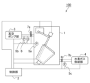
まず、本発明の実施の形態に係る水素化ホウ素化合物製造装置について説明する。図1は、本発明の実施の形態に係る水素化ホウ素化合物製造装置の構成を示す概略図である。図1に示すように、本発明の実施の形態に係る水素化ホウ素化合物製造装置100は、水素化ホウ素化合物生成部1、制御部2、真空ポンプ部3、水素ガス供給部4、圧力計5(5a、5b、及び5c)、湿度計6、及びバルブ7(7a、及び7b)から構成される。 (Boron hydride compound manufacturing equipment)
First, a borohydride compound manufacturing apparatus according to an embodiment of the present invention will be described. FIG. 1 is a schematic diagram showing the configuration of a borohydride compound manufacturing apparatus according to an embodiment of the present invention. As shown in FIG. 1, a borohydridecompound manufacturing apparatus 100 according to an embodiment of the present invention includes a borohydride compound production section 1, a control section 2, a vacuum pump section 3, a hydrogen gas supply section 4, a pressure gauge 5, (5a, 5b, and 5c), a hygrometer 6, and a valve 7 (7a, and 7b).
まず、本発明の実施の形態に係る水素化ホウ素化合物製造装置について説明する。図1は、本発明の実施の形態に係る水素化ホウ素化合物製造装置の構成を示す概略図である。図1に示すように、本発明の実施の形態に係る水素化ホウ素化合物製造装置100は、水素化ホウ素化合物生成部1、制御部2、真空ポンプ部3、水素ガス供給部4、圧力計5(5a、5b、及び5c)、湿度計6、及びバルブ7(7a、及び7b)から構成される。 (Boron hydride compound manufacturing equipment)
First, a borohydride compound manufacturing apparatus according to an embodiment of the present invention will be described. FIG. 1 is a schematic diagram showing the configuration of a borohydride compound manufacturing apparatus according to an embodiment of the present invention. As shown in FIG. 1, a borohydride
水素化ホウ素化合物生成部1は、MαBβOγ(Mはアルカリ金属原子又はアルカリ土類金属原子であり、αは1~4のいずれかの整数であり、βは1~8のいずれかの整数であり、γは1~13のいずれかの整数であり、α、β、γはそれぞれ同じであっても異なるものであってもよい。)で表されるホウ酸化合物と、水素ガス供給部4から供給された水素ガスから、水素化ホウ素化合物を生成するものである。
The borohydride compound generating unit 1 is composed of M α B β O γ (M is an alkali metal atom or an alkaline earth metal atom, α is an integer of 1 to 4, and β is an integer of 1 to 8). is an integer of 1 to 13, γ is an integer of 1 to 13, and α, β, and γ may be the same or different.) and hydrogen. A boron hydride compound is generated from hydrogen gas supplied from the gas supply section 4.
例えば、ホウ酸化合物がメタホウ酸ナトリウム(NaBO2)である場合、下記化学反応式(1)のように、メタホウ酸ナトリウム(NaBO2)は水素ガス(H2)と反応し、水素化ホウ素化合物として水素化ホウ素ナトリウム(NaBH4)を生じる。
NaBO2+4H2 → NaBH4+2H2O ・・・(1) For example, when the boric acid compound is sodium metaborate (NaBO 2 ), the sodium metaborate (NaBO 2 ) reacts with hydrogen gas (H 2 ) as shown in the chemical reaction formula (1) below, and the boron hydride compound As a result, sodium borohydride (NaBH 4 ) is produced.
NaBO 2 +4H 2 → NaBH 4 +2H 2 O...(1)
ホウ酸化合物は、MαBβOγ(Mはアルカリ金属原子又はアルカリ土類金属原子であり、αは1~4のいずれかの整数であり、βは1~8のいずれかの整数であり、γは1~13のいずれかの整数であり、α、β、γはそれぞれ同じであっても異なるものであってもよい。)で表され、水素ガスと反応することで水素化ホウ素化合物を生成するものであればよく、特に限定されない。
The boric acid compound is M α B β O γ (M is an alkali metal atom or an alkaline earth metal atom, α is an integer of 1 to 4, and β is an integer of 1 to 8). γ is an integer from 1 to 13, and α, β, and γ may be the same or different.) By reacting with hydrogen gas, borohydride It is not particularly limited as long as it produces a compound.
ホウ酸化合物は、例えば、メタホウ酸ナトリウム(NaBO2)、四ホウ酸ナトリウム(Na2B4O7)、二ホウ酸ナトリウム(Na4B2O5)、八ホウ酸ナトリウム(Na2B8O13)、五ホウ酸ナトリウム(NaB5O8)、メタホウ酸リチウム(LiBO2)、四ホウ酸リチウム(Li2B4O7)、メタホウ酸カリウム(KBO2)、四ホウ酸カリウム(K2B4O7)、メタホウ酸カルシウム(Ca(BO2)2)、四ホウ酸カルシウム(CaB4O7)などであってよい。
Examples of boric acid compounds include sodium metaborate (NaBO 2 ), sodium tetraborate (Na 2 B 4 O 7 ), sodium diborate (Na 4 B 2 O 5 ), and sodium octaborate (Na 2 B 8 O 13 ), sodium pentaborate (NaB 5 O 8 ), lithium metaborate (LiBO 2 ), lithium tetraborate (Li 2 B 4 O 7 ), potassium metaborate (KBO 2 ), potassium tetraborate (K 2 B 4 O 7 ), calcium metaborate (Ca(BO 2 ) 2 ), calcium tetraborate (CaB 4 O 7 ), and the like.
上記化学反応式(1)に示される反応は可逆反応であり、水素化ホウ素化合物が水と反応すると、水素とメタホウ酸化合物を生じる。そのため、ホウ酸化合物としてメタホウ酸化合物を用いた場合、水素化ホウ素化合物から水素を取り出した後に生じるメタホウ酸化合物を原料として、再度、水素化ホウ素化合物を生成することができる。したがって、資源のリサイクルが可能であるという観点から、ホウ酸化合物はメタホウ酸化合物であることが好ましい。
The reaction shown in the chemical reaction formula (1) above is a reversible reaction, and when a boron hydride compound reacts with water, hydrogen and a metaboric acid compound are generated. Therefore, when a metaboric acid compound is used as the boric acid compound, the boron hydride compound can be generated again using the metaboric acid compound produced after hydrogen is removed from the boron hydride compound as a raw material. Therefore, from the viewpoint of resource recycling, the boric acid compound is preferably a metaboric acid compound.
また、ホウ酸化合物は、水和物であっても無水物であってもよい。ホウ酸化合物が水和物である場合には、ホウ酸化合物に含まれる水分子を除去して無水物とした後に、水素ガスと反応させてもよい。ホウ酸化合物に含まれる水分子を除去する方法は特に限定されない。例えば、ホウ酸化合物を加熱することで水分子を除去してもよく、ホウ酸化合物を乾燥させることで水分子を除去してもよい。
Further, the boric acid compound may be a hydrate or an anhydride. When the boric acid compound is a hydrate, water molecules contained in the boric acid compound may be removed to form an anhydride, and then the boric acid compound may be reacted with hydrogen gas. The method for removing water molecules contained in the boric acid compound is not particularly limited. For example, water molecules may be removed by heating the boric acid compound, or water molecules may be removed by drying the boric acid compound.
さらに、ホウ酸化合物を水素と反応させる際には、触媒を用いてもよく、触媒を用いなくてもよい。ホウ酸化合物を水素と反応させる際に触媒を用いた場合には、水素化ホウ素化合物を生成した後に、水素化ホウ素化合物から触媒を除去することとしてもよい。
Furthermore, when a boric acid compound is reacted with hydrogen, a catalyst may or may not be used. When a catalyst is used when a boric acid compound is reacted with hydrogen, the catalyst may be removed from the boron hydride compound after the boron hydride compound is generated.
水素化ホウ素化合物は、ホウ酸化合物と水素ガスから生成されるものであればよく、特に限定されない。水素化ホウ素化合物は、例えば、水素化ホウ素ナトリウム(NaBH4)、水素化ホウ素カリウム(KBH4)、水素化ホウ素リチウム(LiBH4)、水素化ホウ素カルシウム(Ca(BH4)2)などであってよい。
The boron hydride compound is not particularly limited as long as it is generated from a boric acid compound and hydrogen gas. Examples of the borohydride compound include sodium borohydride (NaBH 4 ), potassium borohydride (KBH 4 ), lithium borohydride (LiBH 4 ), and calcium borohydride (Ca(BH 4 ) 2 ). It's fine.
図2は、本発明の実施の形態に係る水素化ホウ素化合物生成部の構造を説明するための概略図である。図2に示すように、本発明の実施の形態に係る水素化ホウ素化合物生成部1は、撹拌槽11、撹拌棒12、撹拌制御部13(13a、及び13b)、ヒーター14、及びモーター15を備えている。
FIG. 2 is a schematic diagram for explaining the structure of the borohydride compound generating section according to the embodiment of the present invention. As shown in FIG. 2, the borohydride compound generating section 1 according to the embodiment of the present invention includes a stirring tank 11, a stirring rod 12, a stirring control section 13 (13a and 13b), a heater 14, and a motor 15. We are prepared.
撹拌槽11は、撹拌槽11の内部に存在するホウ酸化合物を撹拌するものである。撹拌するための態様は特に限定されず、ホウ酸化合物を撹拌することができればよい。なお、「撹拌」には、棒状、板状、プロペラ状などの撹拌子を用いて材料をかき混ぜることだけではなく、棒状、板状、プロペラ状などの撹拌子を用いずに、材料の位置を変更させることでかき混ぜることも含まれることとする。例えば、撹拌槽11が回転することでホウ酸化合物を撹拌してもよく、撹拌槽11が振動することでホウ酸化合物を撹拌してもよい。ホウ酸化合物を撹拌することで、ホウ酸化合物と水素ガスが接触しやすくなるため、反応速度を上昇させることができる。
The stirring tank 11 is for stirring the boric acid compound present inside the stirring tank 11. The mode for stirring is not particularly limited, as long as the boric acid compound can be stirred. In addition, "stirring" does not only mean stirring the material using a rod-shaped, plate-shaped, or propeller-shaped stirrer, but also stirring the material without using a rod-shaped, plate-shaped, or propeller-shaped stirrer. Changing the ingredients also includes stirring. For example, the boric acid compound may be stirred by the stirring tank 11 rotating, or the boric acid compound may be stirred by the stirring tank 11 vibrating. Stirring the boric acid compound makes it easier for the boric acid compound and hydrogen gas to come into contact with each other, thereby increasing the reaction rate.
また、撹拌槽11の素材、形状、及び大きさは、撹拌槽11の内部にホウ酸化合物を収容し、撹拌することができればよく、特に限定されない。撹拌槽11の素材としては、例えば、耐食性のステンレス、白金、炭素、石英などを用いることができる。また、撹拌槽11の形状としては、例えば、円錐台形状、円筒形状、丸底円柱形状、尖底円柱形状、半球形状、球形状などを採用することができる。
Further, the material, shape, and size of the stirring tank 11 are not particularly limited as long as the boric acid compound can be accommodated and stirred inside the stirring tank 11. As a material for the stirring tank 11, for example, corrosion-resistant stainless steel, platinum, carbon, quartz, etc. can be used. Further, as the shape of the stirring tank 11, for example, a truncated cone shape, a cylindrical shape, a round-bottomed cylindrical shape, a pointed-bottomed cylindrical shape, a hemispherical shape, a spherical shape, etc. can be adopted.
撹拌槽11としては、例えば、耐熱性を有するるつぼを用いてもよく、円筒形状のドラムを用いてもよい。大型のるつぼを用いた場合、2~3トン程度のホウ酸化合物を収容することができる。また、ドラムを用いた場合、るつぼよりも大量のホウ酸化合物を収容することもできる。
As the stirring tank 11, for example, a heat-resistant crucible or a cylindrical drum may be used. When a large crucible is used, about 2 to 3 tons of boric acid compound can be contained. Further, when a drum is used, a larger amount of boric acid compound can be accommodated than a crucible.
図2においては、撹拌槽11の外側に、撹拌槽11を収容するようにヒーター14が備えられている。ヒーター14は、制御部2により、撹拌槽11を加熱するよう制御される。
In FIG. 2, a heater 14 is provided outside the stirring tank 11 so as to accommodate the stirring tank 11. The heater 14 is controlled by the control unit 2 to heat the stirring tank 11 .
ヒーター14は、撹拌槽11を加熱することで、ホウ酸化合物や水素化ホウ素化合物生成部1の内部の温度を上昇させることができる。ホウ酸化合物や水素化ホウ素化合物生成部1の内部の温度が上昇することで、ホウ酸化合物と水素ガスの反応速度を上昇させることができる。また、ホウ酸化合物や水素化ホウ素化合物生成部1の内部の温度が上昇することで、ホウ酸化合物が水和物である場合に、ホウ酸化合物に含まれる水分子を除去することができる。
The heater 14 can raise the temperature inside the boric acid compound or boron hydride compound producing section 1 by heating the stirring tank 11 . By increasing the temperature inside the boric acid compound or boron hydride compound generating section 1, the reaction rate between the boric acid compound and hydrogen gas can be increased. Further, by increasing the temperature inside the boric acid compound or boron hydride compound generating section 1, water molecules contained in the boric acid compound can be removed when the boric acid compound is a hydrate.
ヒーター14により加熱される撹拌槽11の温度は、100℃以上であることが好ましく、150℃以上であることがより好ましく、180℃以上であることがさらに好ましい。また、ヒーター14により加熱される撹拌槽11の温度は、500℃以下であることが好ましく、400℃以下であることがより好ましく、300℃以下であることがさらに好ましい。撹拌槽11の温度が上記範囲内にあることで、つまり、ホウ酸化合物と水素ガスが反応する際の温度が上記範囲内にあることで、ホウ酸化合物と水素ガスの反応速度を好適に保つことができる。
The temperature of the stirring tank 11 heated by the heater 14 is preferably 100°C or higher, more preferably 150°C or higher, and even more preferably 180°C or higher. Further, the temperature of the stirring tank 11 heated by the heater 14 is preferably 500°C or lower, more preferably 400°C or lower, and even more preferably 300°C or lower. By ensuring that the temperature of the stirring tank 11 is within the above range, that is, the temperature at which the boric acid compound and hydrogen gas react is within the above range, the reaction rate of the boric acid compound and hydrogen gas is maintained at a suitable rate. be able to.
また、図2においては、ヒーター14の底部には、ヒーター14と撹拌槽11に動力を伝えるためのモーター15が備えられている。モーター15は、制御部2によりヒーター14、及び撹拌槽11に動力を伝えるよう制御される。モーター15は、ヒーター14、及び撹拌槽11に動力を伝えることで、ホウ酸化合物を撹拌することができる。例えば、モーター15は、ヒーター14、及び撹拌槽11を回転させることでホウ酸化合物を撹拌してもよく、ヒーター14、及び撹拌槽11を振動させることでホウ酸化合物を撹拌してもよい。
Further, in FIG. 2, a motor 15 for transmitting power to the heater 14 and the stirring tank 11 is provided at the bottom of the heater 14. The motor 15 is controlled by the control unit 2 to transmit power to the heater 14 and the stirring tank 11. The motor 15 can stir the boric acid compound by transmitting power to the heater 14 and the stirring tank 11. For example, the motor 15 may stir the boric acid compound by rotating the heater 14 and the stirring tank 11, or may stir the boric acid compound by vibrating the heater 14 and the stirring tank 11.
撹拌槽11が、回転することでホウ酸化合物を撹拌するものである場合には、撹拌槽11の回転速度は、1rpm以上であることが好ましく、5rpm以上であることがより好ましく、10rpm以上であることがさらに好ましい。撹拌槽11の回転速度が上記範囲内にあることで、ホウ酸化合物が効率よく撹拌され、ホウ酸化合物と水素ガスの反応速度を好適に保つことができる。
When the stirring tank 11 rotates to stir the boric acid compound, the rotation speed of the stirring tank 11 is preferably 1 rpm or more, more preferably 5 rpm or more, and more preferably 10 rpm or more. It is even more preferable that there be. When the rotational speed of the stirring tank 11 is within the above range, the boric acid compound can be efficiently stirred, and the reaction rate between the boric acid compound and hydrogen gas can be maintained at a suitable level.
図2においては、モーター15の上面は、水素化ホウ素化合物生成部1の底面と平行ではなく、傾いている。そのため、モーター15の上面に設置されたヒーター14、及び撹拌槽11の中心軸は、重力方向に対して傾斜している。撹拌槽11の中心軸が重力方向に対して傾斜するように設置されることで、ホウ酸化合物を効率よく撹拌することができる。
In FIG. 2, the top surface of the motor 15 is not parallel to the bottom surface of the borohydride compound generating section 1, but is inclined. Therefore, the central axis of the heater 14 installed on the upper surface of the motor 15 and the stirring tank 11 is inclined with respect to the direction of gravity. By installing the stirring tank 11 so that its central axis is inclined with respect to the direction of gravity, the boric acid compound can be efficiently stirred.
撹拌槽11の中心軸の、重力方向に対する傾斜角度は、30°以上であることが好ましく、40°以上であることがより好ましく、45°以上であることがさらに好ましい。また、撹拌槽11の中心軸の、重力方向に対する傾斜角度は、60°以下であることが好ましく、55°以下であることがより好ましく、50°以下であることがさらに好ましい。
The angle of inclination of the central axis of the stirring tank 11 with respect to the direction of gravity is preferably 30° or more, more preferably 40° or more, and even more preferably 45° or more. Further, the angle of inclination of the central axis of the stirring tank 11 with respect to the direction of gravity is preferably 60° or less, more preferably 55° or less, and even more preferably 50° or less.
撹拌槽11の中心軸が重力方向に対して傾斜するように設置することが可能となるためには、例えば、撹拌槽11を水素化ホウ素化合物生成部1の内部に設置する際に用いる土台の上面を、水素化ホウ素化合物生成部1の底面に対して傾斜した構造としてもよい。あるいは、撹拌槽11を水素化ホウ素化合物生成部1の内部に設置する際に用いる土台の上面が可動式であり、水素化ホウ素化合物生成部1の底面に対して傾斜するように動かし、固定することが可能であってもよい。
In order to be able to install the stirring tank 11 so that its central axis is inclined with respect to the direction of gravity, for example, the base used when installing the stirring tank 11 inside the boron hydride compound generating section 1 must be The upper surface may have a structure inclined with respect to the bottom surface of the borohydride compound generating section 1. Alternatively, the top surface of the base used when installing the stirring tank 11 inside the boron hydride compound generation section 1 is movable, and is moved so as to be inclined with respect to the bottom surface of the boron hydride compound generation section 1 and then fixed. It may be possible.
図2においては、撹拌槽11の内部に、回転することでさらにホウ酸化合物を撹拌する撹拌棒12が備えられている。図2においては、撹拌棒12は、撹拌棒12の上部に設置された撹拌制御部13a及び13bにより、回転するように制御される。また、撹拌制御部13a及び13bは、制御部2により制御される。
In FIG. 2, a stirring rod 12 that further stirs the boric acid compound by rotating is provided inside the stirring tank 11. In FIG. 2, the stirring bar 12 is controlled to rotate by stirring control units 13a and 13b installed at the top of the stirring bar 12. Further, the stirring controllers 13a and 13b are controlled by the controller 2.
撹拌棒12は、撹拌槽11の内部において、同じ位置に設置された状態で、撹拌棒12の中心軸を中心に回転することでホウ酸化合物を撹拌してもよく、撹拌槽11の内部において、撹拌棒12自体が撹拌槽11の中心軸を中心に回転させられることでホウ酸化合物を撹拌してもよい。あるいは、撹拌棒12自体が撹拌槽11の中心軸を中心に回転させられ、さらに、撹拌棒12の中心軸を中心に回転することでホウ酸化合物を撹拌してもよい。
The stirring rod 12 may stir the boric acid compound by rotating around the central axis of the stirring rod 12 while being installed at the same position inside the stirring tank 11. The boric acid compound may be stirred by rotating the stirring rod 12 itself around the central axis of the stirring tank 11. Alternatively, the stirring rod 12 itself may be rotated around the central axis of the stirring tank 11, and further rotated around the central axis of the stirring rod 12 to stir the boric acid compound.
撹拌棒12が撹拌棒12の中心軸を中心に回転する際の撹拌棒12の回転速度は、50rpm以上であることが好ましく、100rpm以上であることがより好ましく、150rpm以上であることがさらに好ましい。また、撹拌棒12が撹拌棒12の中心軸を中心に回転する際の撹拌棒12の回転速度は、300rpm以下であることが好ましく、250rpm以下であることがより好ましく、200rpm以下であることがさらに好ましい。撹拌棒12の回転速度が上記範囲内にあることで、ホウ酸化合物が効率よく撹拌され、ホウ酸化合物と水素ガスの反応速度を好適に保つことができる。
The rotational speed of the stirring rod 12 when the stirring rod 12 rotates around the central axis of the stirring rod 12 is preferably 50 rpm or more, more preferably 100 rpm or more, and even more preferably 150 rpm or more. . Further, the rotation speed of the stirring rod 12 when the stirring rod 12 rotates around the central axis of the stirring rod 12 is preferably 300 rpm or less, more preferably 250 rpm or less, and preferably 200 rpm or less. More preferred. When the rotational speed of the stirring rod 12 is within the above range, the boric acid compound can be efficiently stirred, and the reaction rate between the boric acid compound and hydrogen gas can be maintained at a suitable level.
撹拌棒12は、図中の破線矢印16a及び16bの2カ所において可動し、撹拌槽11の外部に取り出すことができる。撹拌槽11の内部に、回転することでさらにホウ酸化合物を撹拌する撹拌棒12が備えられることで、ホウ酸化合物を効率よく撹拌することができる。
The stirring rod 12 is movable at two locations indicated by broken line arrows 16a and 16b in the figure, and can be taken out of the stirring tank 11. The stirring rod 12 that rotates to further stir the boric acid compound is provided inside the stirring tank 11, so that the boric acid compound can be efficiently stirred.
撹拌槽11が回転することでホウ酸化合物を撹拌する場合には、撹拌槽11と撹拌棒12の回転する方向は逆であることが好ましい。つまり、図2に示すように、撹拌槽11が矢印17aで示すように側面視において右方向に回転する場合には、撹拌棒12は矢印17bで示すように側面視において左方向に回転することが好ましい。撹拌槽11と撹拌棒12の回転する方向が逆であることで、ホウ酸化合物を効率よく撹拌することができる。
When stirring the boric acid compound by rotating the stirring tank 11, it is preferable that the directions in which the stirring tank 11 and the stirring rod 12 rotate are opposite to each other. That is, as shown in FIG. 2, when the stirring tank 11 rotates to the right in side view as shown by arrow 17a, stirring bar 12 rotates to the left in side view as shown by arrow 17b. is preferred. By rotating the stirring tank 11 and the stirring rod 12 in opposite directions, the boric acid compound can be efficiently stirred.
撹拌棒12は、撹拌槽11の中心軸に対して、略平行であることが好ましい。あるいは、撹拌棒12は、撹拌槽11の内壁に対して、略平行であってもよい。
It is preferable that the stirring rod 12 is approximately parallel to the central axis of the stirring tank 11. Alternatively, the stirring rod 12 may be substantially parallel to the inner wall of the stirring tank 11.
撹拌棒12の形状は特に限定されず、ホウ酸化合物を撹拌することが可能であればよい。撹拌棒12は、撹拌翼を備えてもよく、撹拌翼を備えなくともよい。撹拌棒12が撹拌翼を備える場合には、撹拌翼の種類は特に限定されず、適宜設計可能である。撹拌翼の種類は、例えば、アンカータイプ、スクリュータイプ、ヘリカルリボンタイプ、パドルタイプ、プロペラタイプ、ベルヌーイタイプなどであってもよい。ホウ酸化合物が水分を含んで粘度の高い状態となった場合にも十分な撹拌能力を得るためには、アンカータイプ、スクリュータイプ、ヘリカルリボンタイプなどを採用することが好ましい。
The shape of the stirring rod 12 is not particularly limited, as long as it can stir the boric acid compound. The stirring rod 12 may be provided with a stirring blade or may not be provided with a stirring blade. When the stirring rod 12 includes stirring blades, the type of stirring blades is not particularly limited and can be designed as appropriate. The type of stirring blade may be, for example, an anchor type, screw type, helical ribbon type, paddle type, propeller type, Bernoulli type, or the like. In order to obtain sufficient stirring ability even when the boric acid compound contains water and becomes highly viscous, it is preferable to use an anchor type, screw type, helical ribbon type, or the like.
また、図示しないが、撹拌棒12には、撹拌槽11の内部の側面に付着したホウ酸化合物を剥離するための剥離手段が備えてられていてもよい。剥離手段は、撹拌槽11の内部の側面に付着したホウ酸化合物を剥離することができれば特に限定されず、適宜設計可能である。剥離手段には、例えば、ブラシやヘラなどを用いることができる。
Although not shown, the stirring rod 12 may be equipped with a peeling means for peeling off the boric acid compound adhering to the inner side surface of the stirring tank 11. The peeling means is not particularly limited as long as it can peel off the boric acid compound adhering to the inner side surface of the stirring tank 11, and can be designed as appropriate. For example, a brush or a spatula can be used as the peeling means.
また、撹拌槽11の内部の側面に付着したホウ酸化合物を剥離するための剥離手段が備えられる箇所は、撹拌棒12でなくともよい。例えば、撹拌槽11に、別途、剥離手段が備えられてもよい。また、撹拌棒12が撹拌翼を備える場合には、撹拌翼が剥離手段としても機能するようにしてもよい。
Further, the location where a peeling means for peeling off the boric acid compound adhering to the inner side surface of the stirring tank 11 is provided may not be the stirring rod 12. For example, the stirring tank 11 may be provided with a separate peeling means. Moreover, when the stirring rod 12 is provided with a stirring blade, the stirring blade may also function as a peeling means.
水素化ホウ素化合物製造装置100が撹拌槽11の内部の側面に付着したホウ酸化合物を剥離するための剥離手段を備えることで、ホウ酸化合物が撹拌槽11の内部の側面に付着した場合にも、ホウ酸化合物を効率よく撹拌することができる。
By providing the boron hydride compound manufacturing apparatus 100 with a peeling means for peeling off the boric acid compound adhering to the inner side surface of the stirring tank 11, even if the boric acid compound adheres to the inner side surface of the stirring tank 11, it can be removed. , boric acid compounds can be efficiently stirred.
また、図2においては、撹拌棒12は、撹拌槽11の内部の側面近傍に配置されている。撹拌棒12が撹拌槽11の内部の側面近傍に配置されることで、ホウ酸化合物が水分を含んで粘度の高い状態となった場合にも、撹拌棒12にかかる負荷を軽減することができる。また、撹拌棒12に撹拌槽11の内部の側面に付着したホウ酸化合物を剥離するための剥離手段が備えてられている場合には、撹拌棒12が撹拌槽11の内部の側面近傍に配置されることで、撹拌槽11の内壁と撹拌棒12の距離が近づくため、ホウ酸化合物を剥離しやすくなる。
Further, in FIG. 2, the stirring rod 12 is arranged near the side surface inside the stirring tank 11. By disposing the stirring rod 12 near the side surface inside the stirring tank 11, even when the boric acid compound contains water and becomes highly viscous, the load on the stirring rod 12 can be reduced. . In addition, when the stirring rod 12 is equipped with a peeling means for peeling off the boric acid compound adhering to the inner side surface of the stirring tank 11, the stirring rod 12 is placed near the inner side surface of the stirring tank 11. By doing so, the distance between the inner wall of the stirring tank 11 and the stirring rod 12 becomes closer, making it easier to peel off the boric acid compound.
撹拌槽11の内部の側面近傍とは、例えば、撹拌槽11の内径をrとしたとき、撹拌槽11の内部の側面から、側面に対して垂直な方向に(1/2)×rの距離内のことでもよく、撹拌槽11の内部の側面から、側面に対して垂直な方向に(1/4)×rの距離内のことでもよく、撹拌槽11の内部の側面から、側面に対して垂直な方向に(1/6)×rの距離内のことでもよく、撹拌槽11の内部の側面から、側面に対して垂直な方向に(1/8)×rの距離内のことでもよい。
The vicinity of the inner side surface of the stirring tank 11 is, for example, a distance of (1/2) x r from the inner side surface of the stirring tank 11 in the direction perpendicular to the side surface, where r is the inner diameter of the stirring tank 11. It may be within a distance of (1/4) x r from the side of the inside of the stirring tank 11 in the direction perpendicular to the side, or from the side of the inside of the stirring tank 11 to the side. It may be within a distance of (1/6) x r in the direction perpendicular to the stirring tank 11, or it may be within a distance of (1/8) x r from the side of the inside of the stirring tank 11 in the direction perpendicular to the side. good.
図1に示すように、水素化ホウ素化合物生成部1には、圧力計5aが備えられていてもよい。圧力計5aにより、水素化ホウ素化合物生成部1の内部の圧力を計測することができる。また、圧力計5aにより計測された水素化ホウ素化合物生成部1の内部の圧力の数値は、制御部2に伝達されることとしてもよい。制御部2は、水素化ホウ素化合物生成部1の内部の圧力の数値に基づき、真空ポンプ部3や水素ガス供給部4の動作を制御することができる。
As shown in FIG. 1, the borohydride compound generating section 1 may be equipped with a pressure gauge 5a. The pressure inside the borohydride compound generating section 1 can be measured by the pressure gauge 5a. Further, the numerical value of the internal pressure of the boron hydride compound generating section 1 measured by the pressure gauge 5a may be transmitted to the control section 2. The control unit 2 can control the operation of the vacuum pump unit 3 and the hydrogen gas supply unit 4 based on the numerical value of the internal pressure of the boron hydride compound generation unit 1.
真空ポンプ部3は、水素化ホウ素化合物生成部1内の気体を排出し、水素化ホウ素化合物生成部1内を真空、又は真空に近い状態とするものである。図1に示すように、真空ポンプ部3は、水素化ホウ素化合物生成部1とパイプなどで接続されている。また、水素化ホウ素化合物生成部1と真空ポンプ部3を接続するパイプには、バルブ7a、圧力計5b、及び湿度計6が備えられている。
The vacuum pump section 3 discharges the gas inside the boron hydride compound generating section 1 and brings the inside of the boron hydride compound generating section 1 into a vacuum or near-vacuum state. As shown in FIG. 1, the vacuum pump section 3 is connected to the borohydride compound generating section 1 through a pipe or the like. Further, a pipe connecting the boron hydride compound generating section 1 and the vacuum pump section 3 is equipped with a valve 7a, a pressure gauge 5b, and a hygrometer 6.
真空ポンプ部3、及びバルブ7aは、制御部2により制御することができる。バルブ7aは、パイプの開閉ができるものであればよく、電磁式バルブや電動式バルブなど用いることができる。
The vacuum pump section 3 and the valve 7a can be controlled by the control section 2. The valve 7a may be anything that can open and close the pipe, and may be an electromagnetic valve, an electric valve, or the like.
また、圧力計5bにより計測された真空ポンプ部3側の圧力の数値、及び、湿度計6により計測された真空ポンプ部3側の湿度の数値は、制御部2に伝達されることとしてもよい。制御部2は、真空ポンプ部3側の圧力の数値、及び、真空ポンプ部3側の湿度の数値に基づき、真空ポンプ部3の動作を制御することができる。
Further, the numerical value of the pressure on the vacuum pump section 3 side measured by the pressure gauge 5b and the numerical value of the humidity on the vacuum pump section 3 side measured by the hygrometer 6 may be transmitted to the control section 2. . The control unit 2 can control the operation of the vacuum pump unit 3 based on the pressure value on the vacuum pump unit 3 side and the humidity value on the vacuum pump unit 3 side.
真空ポンプ部3は、水素化ホウ素化合物生成部1内の気体を排出し、水素化ホウ素化合物生成部1内を真空にすることができればよく、特に限定されない。真空ポンプ部3は、複数のポンプを組み合わせた構造であってもよい。例えば、真空ポンプ部3は、真空まで排気することが可能な主ポンプと、大気圧から主ポンプが作動できる圧力まで排気する補助ポンプとを組み合わせた構造であってもよい。
The vacuum pump section 3 is not particularly limited as long as it can exhaust the gas inside the borohydride compound generating section 1 and make the inside of the borohydride compound generating section 1 a vacuum. The vacuum pump section 3 may have a structure in which a plurality of pumps are combined. For example, the vacuum pump section 3 may have a structure that combines a main pump capable of evacuation to vacuum and an auxiliary pump that evacuation from atmospheric pressure to a pressure at which the main pump can operate.
また、水素化ホウ素化合物生成部1は、真空ポンプ部3により真空、又は真空に近い状態にできるよう、機密性の高い構造であることが好ましい。
Furthermore, the boron hydride compound generating section 1 preferably has a highly airtight structure so that it can be brought into a vacuum or near-vacuum state by the vacuum pump section 3.
真空ポンプ部3は、ホウ酸化合物が水和物であった場合に、ホウ酸化合物を加熱して発生した水蒸気を水素化ホウ素化合物生成部1から排出することができる。
When the boric acid compound is a hydrate, the vacuum pump section 3 can discharge water vapor generated by heating the boric acid compound from the boron hydride compound generating section 1.
また、真空ポンプ部3が水素化ホウ素化合物生成部1内を真空、又は真空に近い状態にした後に、水素化ホウ素化合物生成部1内に水素ガスが供給されることで、ホウ酸化合物と水素ガスが接触しやすくなるため、ホウ酸化合物と水素ガスの反応速度を上昇させることができる。
Further, after the vacuum pump section 3 makes the inside of the boron hydride compound generating section 1 a vacuum or a near-vacuum state, hydrogen gas is supplied into the boron hydride compound generating section 1, so that the boric acid compound and hydrogen Since the gases come into contact with each other more easily, the reaction rate between the boric acid compound and hydrogen gas can be increased.
水素ガス供給部4は、水素化ホウ素化合物生成部1内に水素ガスを供給するものである。図1に示すように、水素化ホウ素化合物生成部1と水素ガス供給部4は、パイプなどで接続されている。また、水素化ホウ素化合物生成部1と水素ガス供給部4を接続するパイプには、バルブ7b、圧力計5cが備えられている。
The hydrogen gas supply section 4 supplies hydrogen gas into the boron hydride compound generation section 1. As shown in FIG. 1, the borohydride compound generating section 1 and the hydrogen gas supply section 4 are connected by a pipe or the like. Further, a pipe connecting the boron hydride compound generating section 1 and the hydrogen gas supply section 4 is equipped with a valve 7b and a pressure gauge 5c.
水素ガス供給部4、及びバルブ7bは、制御部2により制御することができる。バルブ7bは、パイプの開閉ができるものであればよく、電磁式バルブや電動式バルブなど用いることができる。
The hydrogen gas supply section 4 and the valve 7b can be controlled by the control section 2. The valve 7b may be anything that can open and close the pipe, and may be an electromagnetic valve, an electric valve, or the like.
また、圧力計5cにより計測された水素ガス供給部4側の圧力の数値は、制御部2に伝達されることとしてもよい。制御部2は、水素ガス供給部4側の圧力の数値に基づき、水素ガス供給部4の動作を制御することができる。
Furthermore, the numerical value of the pressure on the hydrogen gas supply section 4 side measured by the pressure gauge 5c may be transmitted to the control section 2. The control unit 2 can control the operation of the hydrogen gas supply unit 4 based on the numerical value of the pressure on the hydrogen gas supply unit 4 side.
水素ガス供給部4は、水素化ホウ素化合物生成部1内に水素ガスを供給することができればよく、特に限定されない。水素ガス供給部4には、例えば、水素ガスを充填したタンクなどを採用してもよい。
The hydrogen gas supply section 4 is not particularly limited as long as it can supply hydrogen gas into the boron hydride compound generation section 1. The hydrogen gas supply section 4 may be, for example, a tank filled with hydrogen gas.
また、水素化ホウ素化合物生成部1は、水素ガス供給部4により供給された水素を密閉できるよう、機密性の高い構造であることが好ましい。
Furthermore, the boron hydride compound generating section 1 preferably has a highly airtight structure so that the hydrogen supplied by the hydrogen gas supply section 4 can be sealed.
水素ガス供給部4が水素化ホウ素化合物生成部1内に水素ガスを供給することで、ホウ酸化合物と水素ガスが接触するため、ホウ酸化合物と水素ガスを反応させ、水素化ホウ素化合物を得ることができる。
When the hydrogen gas supply section 4 supplies hydrogen gas into the boron hydride compound generation section 1, the boric acid compound and hydrogen gas come into contact with each other, so that the boric acid compound and hydrogen gas are reacted to obtain a boron hydride compound. be able to.
制御部2は、上述のように、撹拌制御部13、ヒーター14、モーター15、真空ポンプ部3、水素ガス供給部4、及びバルブ7の動作を制御する。また、制御部2は、上述のように、圧力計5、及び湿度計6により計測された数値を取得する。制御部2と、撹拌制御部13、ヒーター14、モーター15、真空ポンプ部3、水素ガス供給部4、圧力計5、湿度計6、及びバルブ7のそれぞれは、通信により接続されていてもよく、導線などにより電気的に接続されていてもよい。
As described above, the control unit 2 controls the operations of the stirring control unit 13, heater 14, motor 15, vacuum pump unit 3, hydrogen gas supply unit 4, and valve 7. Further, the control unit 2 obtains numerical values measured by the pressure gauge 5 and the hygrometer 6, as described above. The control unit 2, the stirring control unit 13, the heater 14, the motor 15, the vacuum pump unit 3, the hydrogen gas supply unit 4, the pressure gauge 5, the hygrometer 6, and the valve 7 may be connected via communication. , may be electrically connected by a conductive wire or the like.
また、図示しないが、水素化ホウ素化合物製造装置100には、水素化ホウ素化合物の製造の開始、及び/又は終了を指示するための入力部が備えられていてもよい。水素化ホウ素化合物の製造の開始、及び/又は終了は、制御部2により制御されてもよい。
Although not shown, the borohydride compound production apparatus 100 may be equipped with an input unit for instructing the start and/or end of the production of the borohydride compound. The start and/or end of the production of the borohydride compound may be controlled by the control unit 2.
さらに、図示しないが、水素化ホウ素化合物製造装置100には、水素化ホウ素化合物生成部1内を冷却するための冷却手段が備えられていてもよい。
Furthermore, although not shown, the borohydride compound production apparatus 100 may be equipped with a cooling means for cooling the inside of the borohydride compound production section 1.
また、水素化ホウ素化合物製造装置100には、水素化ホウ素化合物製造装置100内の気体を水素化ホウ素化合物製造装置100外に排出する排気手段が備えられていてもよい。例えば、水素化ホウ素化合物製造装置100には、水素化ホウ素化合物生成部1の内部の気体を水素化ホウ素化合物生成部1及び/又は水素化ホウ素化合物製造装置100の外部に排出する排気手段が備えられてもよい。
Further, the borohydride compound manufacturing apparatus 100 may be equipped with an exhaust means for discharging the gas inside the borohydride compound manufacturing apparatus 100 to the outside of the borohydride compound manufacturing apparatus 100. For example, the borohydride compound production apparatus 100 includes an exhaust means for discharging the gas inside the borohydride compound production section 1 to the outside of the borohydride compound production section 1 and/or the borohydride compound production apparatus 100. It's okay to be hit.
水素化ホウ素化合物生成部1内に水素ガスが供給される速度が、水素ガスがホウ酸化合物と反応して減少する速度よりも早い場合などには、水素化ホウ素化合物生成部1内の水素ガスの濃度及び圧力が上昇し、爆発する危険が高まる。水素化ホウ素化合物製造装置100が排気手段を備えることで、爆発の危険を低下させることができる。
When the rate at which hydrogen gas is supplied into the borohydride compound generating section 1 is faster than the rate at which hydrogen gas reacts with the boric acid compound and decreases, the hydrogen gas within the borohydride compound generating section 1 concentration and pressure will increase, increasing the risk of explosion. By providing the borohydride compound manufacturing apparatus 100 with an exhaust means, the risk of explosion can be reduced.
図3は、本発明の実施の形態に係る水素化ホウ素化合物製造装置の排気の機構を説明するための概略図である。
FIG. 3 is a schematic diagram for explaining the exhaust mechanism of the borohydride compound production apparatus according to the embodiment of the present invention.
水素化ホウ素化合物製造装置100には、パージ弁21(21a、21b、・・・、21z)、制御装置22、手動ボタン23、圧力センサ24、及び水素濃度センサ25が備えられていてもよい。図3に示すように、パージ弁21(21a、21b、・・・、21z)、制御装置22、手動ボタン23、圧力センサ24、及び水素濃度センサ25のそれぞれは、通信により接続されていてもよく、導線などにより電気的に接続されていてもよい。
The borohydride compound manufacturing apparatus 100 may be equipped with a purge valve 21 (21a, 21b, . . . , 21z), a control device 22, a manual button 23, a pressure sensor 24, and a hydrogen concentration sensor 25. As shown in FIG. 3, the purge valves 21 (21a, 21b, ..., 21z), the control device 22, the manual button 23, the pressure sensor 24, and the hydrogen concentration sensor 25 may be connected by communication. Alternatively, they may be electrically connected by a conductive wire or the like.
パージ弁21は、水素化ホウ素化合物製造装置100内の気体を水素化ホウ素化合物製造装置100外に排出するためのバルブである。パージ弁21は、水素化ホウ素化合物生成部1の内部の気体を水素化ホウ素化合物生成部1及び/又は水素化ホウ素化合物製造装置100の外部に排出するためのバルブであってもよい。
The purge valve 21 is a valve for discharging the gas inside the borohydride compound manufacturing apparatus 100 to the outside of the borohydride compound manufacturing apparatus 100. The purge valve 21 may be a valve for discharging the gas inside the borohydride compound generating section 1 to the outside of the borohydride compound generating section 1 and/or the borohydride compound manufacturing apparatus 100.
水素化ホウ素化合物製造装置100においてパージ弁21が備えられる箇所は、特に限定されない。例えば、パージ弁21は、水素化ホウ素化合物生成部1と水素化ホウ素化合物生成部1及び/又は水素化ホウ素化合物製造装置100の外部とを繋ぐパージ管に備えられてもよい。パージ弁21が該パージ管に備えられている場合、パージ弁21を開弁することで、パージ管を開き、水素化ホウ素化合物生成部1の内部の気体を水素化ホウ素化合物生成部1及び/又は水素化ホウ素化合物製造装置100の外部に排出することができる。パージ弁21としては、電磁式のものや、電動式のものを用いることができる。
The location where the purge valve 21 is provided in the borohydride compound manufacturing apparatus 100 is not particularly limited. For example, the purge valve 21 may be provided in a purge pipe that connects the borohydride compound production section 1 and the outside of the borohydride compound production section 1 and/or the borohydride compound production apparatus 100. When the purge pipe is equipped with the purge valve 21, the purge pipe is opened by opening the purge valve 21, and the gas inside the borohydride compound generating unit 1 is discharged from the borohydride compound generating unit 1 and/or the purge pipe. Alternatively, it can be discharged to the outside of the borohydride compound manufacturing apparatus 100. As the purge valve 21, an electromagnetic type or an electric type can be used.
図3においては、水素化ホウ素化合物製造装置100は複数のパージ弁21を備えているが、水素化ホウ素化合物製造装置100が備えるパージ弁21の数は、1以上であればよい。水素化ホウ素化合物製造装置100が備えるパージ弁21の数は、水素化ホウ素化合物製造装置100の大きさなどに応じて、適宜設計可能である。水素化ホウ素化合物製造装置100が複数のパージ弁21を備えている場合、複数のパージ弁21は、制御装置22により、略同時に開弁及び/又は閉弁するように制御されてもよい。
In FIG. 3, the borohydride compound manufacturing apparatus 100 is equipped with a plurality of purge valves 21, but the number of purge valves 21 provided in the borohydride compound manufacturing apparatus 100 may be one or more. The number of purge valves 21 included in the borohydride compound manufacturing apparatus 100 can be appropriately designed depending on the size of the borohydride compound manufacturing apparatus 100 and the like. When the borohydride compound manufacturing apparatus 100 includes a plurality of purge valves 21, the plurality of purge valves 21 may be controlled by the control device 22 to open and/or close substantially simultaneously.
制御装置22は、パージ弁21の開閉を制御するものである。制御装置22は、圧力センサ24及び/又は水素濃度センサ25により計測された情報に基づいて、パージ弁21の開閉を制御してもよい。圧力センサ24は、水素化ホウ素化合物生成部1の内部の圧力を計測することができる。また、水素濃度センサ25は、水素化ホウ素化合物生成部1の内部の水素ガスの濃度を計測することができる。圧力センサ24により計測された水素化ホウ素化合物生成部1の内部の圧力の数値、及び/又は、水素濃度センサ25により計測された水素化ホウ素化合物生成部1の内部の水素ガスの濃度の数値は、制御部22に伝達されることとしてもよい。圧力センサ24により計測された圧力が所定の条件を満たした場合、及び/又は、水素濃度センサ25により計測された水素ガスの濃度が条件を満たした場合には、制御装置22は、パージ弁21を開弁するように制御してもよい。
The control device 22 controls opening and closing of the purge valve 21. The control device 22 may control opening and closing of the purge valve 21 based on information measured by the pressure sensor 24 and/or the hydrogen concentration sensor 25. The pressure sensor 24 can measure the pressure inside the borohydride compound generating section 1 . Furthermore, the hydrogen concentration sensor 25 can measure the concentration of hydrogen gas inside the boron hydride compound generating section 1 . The numerical value of the pressure inside the boron hydride compound generating section 1 measured by the pressure sensor 24 and/or the numerical value of the concentration of hydrogen gas inside the boron hydride compound generating section 1 measured by the hydrogen concentration sensor 25 is , may be transmitted to the control unit 22. When the pressure measured by the pressure sensor 24 satisfies a predetermined condition and/or when the concentration of hydrogen gas measured by the hydrogen concentration sensor 25 satisfies the condition, the control device 22 controls the purge valve 21 It may also be controlled to open the valve.
圧力センサ24により計測された圧力が所定の条件を満たした場合とは、例えば、圧力センサ24により計測された圧力が所定の値以上となった場合でもよく、圧力センサ24により計測された圧力が所定の値より大きくなった場合でもよい。所定の値は、例えば、5atmでもよく、6atmでもよく、7atmでもよい。
The case where the pressure measured by the pressure sensor 24 satisfies a predetermined condition may be, for example, the case where the pressure measured by the pressure sensor 24 exceeds a predetermined value; A case where the value becomes larger than a predetermined value is also acceptable. The predetermined value may be, for example, 5 atm, 6 atm, or 7 atm.
水素濃度センサ25により計測された水素ガスの濃度が条件を満たした場合とは、例えば、水素濃度センサ25により計測された水素ガスの濃度が所定の濃度の範囲内となった場合でもよい。所定の濃度の範囲内は、例えば、3.0体積%以上、80体積%以下の範囲内でもよく、3.5体積%以上、78体積%以下の範囲内でもよく、3.0体積%以上、75体積%以下の範囲内でもよい。
The case where the concentration of hydrogen gas measured by the hydrogen concentration sensor 25 satisfies the conditions may be, for example, the case where the concentration of hydrogen gas measured by the hydrogen concentration sensor 25 falls within a predetermined concentration range. The predetermined concentration range may be, for example, 3.0 volume% or more and 80 volume% or less, 3.5 volume% or more and 78 volume% or less, or 3.0 volume% or more. , 75% by volume or less.
圧力センサ24及び水素濃度センサ25は、水素化ホウ素化合物生成部1に備えられてもよい。圧力センサ24及び水素濃度センサ25は、特に限定されないが、高温環境下でも機能するものであることが好ましい。
The pressure sensor 24 and the hydrogen concentration sensor 25 may be provided in the boron hydride compound generation unit 1. Although the pressure sensor 24 and the hydrogen concentration sensor 25 are not particularly limited, it is preferable that they function even in a high temperature environment.
また、制御装置22は、作業者などからの操作に応じて、パージ弁21の開閉を制御してもよい。例えば、制御装置22は、手動ボタン23が押下された場合に、パージ弁21を開弁及び/又は閉弁するように制御してもよい。この場合、手動ボタン23が押下されたときに発生する信号が、制御部22に伝達されることとしてもよい。
Furthermore, the control device 22 may control opening and closing of the purge valve 21 in response to an operation from an operator or the like. For example, the control device 22 may control the purge valve 21 to open and/or close when the manual button 23 is pressed. In this case, a signal generated when the manual button 23 is pressed may be transmitted to the control unit 22.
制御装置22が、作業者などからの操作に応じてパージ弁21の開閉を制御することで、作業者などが水素化ホウ素化合物生成部1の扉を開く前に、水素化ホウ素化合物生成部1の内部の気体を排気することが可能となる。そのため、作業者などが水素化ホウ素化合物を取り出す際の安全性を高めることができる。また、圧力センサ24及び/又は水素濃度センサ25が故障した場合にも、作業者などの判断で水素化ホウ素化合物生成部1の内部の気体を排気することが可能となる。
The control device 22 controls the opening and closing of the purge valve 21 in accordance with the operation from the operator, etc., so that the borohydride compound generating section 1 is closed before the operator or the like opens the door of the borohydride compound generating section 1. It becomes possible to exhaust the gas inside. Therefore, safety when a worker or the like takes out the boron hydride compound can be improved. Moreover, even if the pressure sensor 24 and/or the hydrogen concentration sensor 25 are out of order, the gas inside the boron hydride compound generating section 1 can be exhausted at the discretion of an operator or the like.
制御装置22は、水素化ホウ素化合物製造装置100が備える制御部2と異なるものであってもよく、同じものであってもよい。制御装置22が制御部2と異なるものである場合、すなわち、水素化ホウ素化合物製造装置100が、水素化ホウ素化合物の製造に関する制御を行う制御部2と、水素化ホウ素化合物生成部1の内部の排気に関する制御を行う制御装置22とをそれぞれ別個に備えている場合、制御部2が故障したときにも、水素化ホウ素化合物生成部1の内部の排気に関する制御を行うことが可能となる。
The control device 22 may be different from the control section 2 included in the borohydride compound manufacturing apparatus 100, or may be the same. When the control device 22 is different from the control section 2, that is, the borohydride compound production apparatus 100 has a control section 2 that controls the production of the borohydride compound and an internal control section 1 of the borohydride compound production section 1. When the control devices 22 for controlling exhaust gas are separately provided, even if the control section 2 fails, it is possible to control the exhaust gas inside the boron hydride compound generating section 1.
また、制御装置22に電力を供給する電源は、水素化ホウ素化合物製造装置100が備える制御部2に電力を供給する電源と異なるものであってもよく、同じものであってもよい。制御装置22に電力を供給する電源が制御部2に電力を供給する電源と異なるものである場合、すなわち、水素化ホウ素化合物製造装置100が、水素化ホウ素化合物の製造に関する制御を行う制御部2に電力を供給する電源と、水素化ホウ素化合物生成部1の内部の排気に関する制御を行う制御装置22に電力を供給する電源とをそれぞれ別個に備えている場合、制御部2に電力を供給する電源が故障したときにも、水素化ホウ素化合物生成部1の内部の排気に関する制御を行うことが可能となる。
Furthermore, the power supply that supplies power to the control device 22 may be different from the power supply that supplies power to the control unit 2 included in the borohydride compound manufacturing apparatus 100, or may be the same power supply. When the power supply that supplies power to the control device 22 is different from the power supply that supplies power to the control unit 2, that is, the borohydride compound manufacturing apparatus 100 uses the control unit 2 that performs control regarding the production of the borohydride compound. and a power supply that supplies power to the control device 22 that controls the internal exhaust of the boron hydride compound generating section 1 are provided separately, the power supply supplies the control section 2 with power. Even when the power supply fails, it becomes possible to control the exhaust gas inside the borohydride compound generating section 1.
また、水素化ホウ素化合物製造装置100は、防爆構造を有していることが好ましい。防爆構造は、例えば、耐圧防爆構造であってもよい。
Moreover, it is preferable that the borohydride compound manufacturing apparatus 100 has an explosion-proof structure. The explosion-proof structure may be, for example, a pressure-resistant explosion-proof structure.
(水素化ホウ素化合物の製造方法)
次に、本発明の実施の形態に係る水素化ホウ素化合物の製造方法について説明する。以下においては、図1に示すような水素化ホウ素化合物製造装置100によって水素化ホウ素化合物を製造する方法について説明する。以下に示す各工程の順序は、適宜前後してもよい。また、以下に示す工程の一部を省略することも可能である。さらに、以下に示す工程に、他の工程を追加することも可能である。 (Method for producing borohydride compound)
Next, a method for producing a borohydride compound according to an embodiment of the present invention will be described. Below, a method for manufacturing a borohydride compound using the borohydridecompound manufacturing apparatus 100 as shown in FIG. 1 will be described. The order of each step shown below may be changed as appropriate. Moreover, it is also possible to omit some of the steps shown below. Furthermore, it is also possible to add other steps to the steps shown below.
次に、本発明の実施の形態に係る水素化ホウ素化合物の製造方法について説明する。以下においては、図1に示すような水素化ホウ素化合物製造装置100によって水素化ホウ素化合物を製造する方法について説明する。以下に示す各工程の順序は、適宜前後してもよい。また、以下に示す工程の一部を省略することも可能である。さらに、以下に示す工程に、他の工程を追加することも可能である。 (Method for producing borohydride compound)
Next, a method for producing a borohydride compound according to an embodiment of the present invention will be described. Below, a method for manufacturing a borohydride compound using the borohydride
まず、水素化ホウ素化合物生成部1内の、撹拌槽11の内部に、ホウ酸化合物が投入される。ホウ酸化合物の投入量は、撹拌槽11の容量により適宜調整することが好ましい。ホウ酸化合物の投入は、手動で行われてもよく、自動で行われてもよい。ホウ酸化合物の投入が自動で行われる場合には、水素化ホウ素化合物生成部1に自動投入口などが備えられていることが好ましい。
First, a boric acid compound is introduced into the stirring tank 11 in the boron hydride compound generating section 1 . It is preferable that the amount of the boric acid compound added is adjusted as appropriate depending on the capacity of the stirring tank 11. The boric acid compound may be added manually or automatically. When the boric acid compound is automatically introduced, it is preferable that the boron hydride compound generating section 1 is equipped with an automatic inlet or the like.
次に、撹拌槽11の内部に、撹拌棒12が配置される。撹拌棒12は、撹拌制御部13の近傍に備わる可動部を動かすことで、撹拌槽11の内部に配置することができる。
Next, a stirring rod 12 is placed inside the stirring tank 11. The stirring rod 12 can be placed inside the stirring tank 11 by moving a movable part provided near the stirring control section 13.
なお、撹拌槽11は、図2に示すように、重力方向に対して中心軸が傾斜するように設置されている。また、撹拌棒12は、図2に示すように、撹拌槽11の内部の側面近傍に配置されている。
Note that, as shown in FIG. 2, the stirring tank 11 is installed so that its central axis is inclined with respect to the direction of gravity. Further, as shown in FIG. 2, the stirring rod 12 is arranged near the side surface inside the stirring tank 11.
水素化ホウ素化合物生成部1が密閉され、水素化ホウ素化合物製造装置100に備えられた水素化ホウ素化合物の製造開始ボタンが押下されると、制御部2は、水素化ホウ素化合物の製造を開始するように制御する。
When the boron hydride compound production unit 1 is sealed and the button for starting production of the boron hydride compound provided in the boron hydride compound production apparatus 100 is pressed, the control unit 2 starts production of the boron hydride compound. Control as follows.
制御部2は、まず、水素化ホウ素化合物生成部1内のモーター15が、撹拌槽11に動力を出力するよう制御する。ここでは、制御部2は、モーター15により撹拌槽11を回転させるように制御することとする。また、制御部2は、撹拌制御部13を介して、撹拌棒12が回転するように制御する。図2に示すように、撹拌槽11と撹拌棒12の回転する方向は、逆方向とする。傾斜撹拌槽11及び撹拌棒12の回転と、撹拌槽11自体の傾斜とにより、ホウ酸化合物は効率よく撹拌される。
First, the control unit 2 controls the motor 15 in the borohydride compound generation unit 1 to output power to the stirring tank 11. Here, the control unit 2 controls the stirring tank 11 to be rotated by the motor 15. Further, the control unit 2 controls the stirring rod 12 to rotate via the stirring control unit 13 . As shown in FIG. 2, the stirring tank 11 and the stirring rod 12 rotate in opposite directions. The boric acid compound is efficiently stirred by the rotation of the inclined stirring tank 11 and the stirring rod 12, and the inclination of the stirring tank 11 itself.
また、ここでは、撹拌棒12には、撹拌槽11の内部の側面に付着したホウ酸化合物を剥離するための剥離手段として、ブラシが備えられてることとする。撹拌棒12に備えられたブラシが、撹拌槽11の内壁に付着したホウ酸化合物を剥離することで、より効率的にホウ酸化合物を撹拌することができる。
Furthermore, here, it is assumed that the stirring rod 12 is equipped with a brush as a peeling means for peeling off the boric acid compound adhering to the inner side surface of the stirring tank 11. The brush provided on the stirring rod 12 peels off the boric acid compound adhering to the inner wall of the stirring tank 11, so that the boric acid compound can be stirred more efficiently.
また、制御部2は、ヒーター14が作動するように制御する。制御部2は、撹拌槽11を所定の温度に保つように制御する。所定の温度は、例えば、200℃であってもよい。
Additionally, the control unit 2 controls the heater 14 to operate. The control unit 2 controls the stirring tank 11 to maintain it at a predetermined temperature. The predetermined temperature may be, for example, 200°C.
ホウ酸化合物が水和物である場合には、撹拌槽11が加熱されることにより、ホウ酸化合物に含まれる水分子が蒸発する。ホウ酸化合物が撹拌されているため、ホウ酸化合物に含まれる水分子は効率よく蒸発する。
When the boric acid compound is a hydrate, water molecules contained in the boric acid compound are evaporated by heating the stirring tank 11. Since the boric acid compound is stirred, water molecules contained in the boric acid compound evaporate efficiently.
水分子が蒸発することにより、水素化ホウ素化合物生成部1内の圧力が上昇したことを圧力計5aにより検出すると、制御部2は、バルブ7aを開き、真空ポンプ部3により水素化ホウ素化合物生成部1内の圧力を低下させるように制御する。真空ポンプ部3は、水素化ホウ素化合物生成部1内の水蒸気と空気を排気することで水素化ホウ素化合物生成部1内の圧力を低下させる。
When the pressure gauge 5a detects that the pressure inside the borohydride compound generating section 1 has increased due to evaporation of water molecules, the control section 2 opens the valve 7a and causes the vacuum pump section 3 to generate the borohydride compound. Control is performed to reduce the pressure within section 1. The vacuum pump section 3 lowers the pressure inside the borohydride compound generating section 1 by exhausting water vapor and air inside the borohydride compound generating section 1 .
制御部2は、水素化ホウ素化合物生成部1内に備えられた圧力計5a、真空ポンプ部3側に備えられた圧力計5b、湿度計6により計測された数値を基に、真空ポンプ部3の制御を行う。水素化ホウ素化合物生成部1内での水蒸気の発生が終了し、水素化ホウ素化合物生成部1内がほぼ真空になった場合には、制御部2は、バルブ7aを閉じ、真空ポンプ部3の動作を停止するよう制御する。
The control unit 2 controls the vacuum pump unit 3 based on the values measured by a pressure gauge 5a provided in the boron hydride compound generation unit 1, a pressure gauge 5b provided on the vacuum pump unit 3 side, and a hygrometer 6. control. When the generation of water vapor in the boron hydride compound generating section 1 is finished and the inside of the boron hydride compound generating section 1 becomes almost vacuum, the control section 2 closes the valve 7a and turns off the vacuum pump section 3. Control to stop operation.
ホウ酸化合物が無水物である場合には、ホウ酸化合物から水蒸気は発生しないが、上記と同様に、制御部2がバルブ7aを開き、真空ポンプ部3により水素化ホウ素化合物生成部1内の圧力を低下させるように制御することで、水素化ホウ素化合物生成部1内をほぼ真空にすることができる。
When the boric acid compound is an anhydride, no water vapor is generated from the boric acid compound, but in the same way as above, the control section 2 opens the valve 7a and the vacuum pump section 3 causes the borohydride compound generating section 1 to be pumped. By controlling the pressure to decrease, the interior of the borohydride compound generating section 1 can be made almost vacuum.
その後、制御部2は、水素ガス供給部4側の圧力計5cにより計測された水素ガス供給部4側の圧力の数値が正常である場合には、バルブ7bを開き、水素ガス供給部4により水素化ホウ素化合物生成部1内に水素ガスを供給するように制御する。図示しないが、水素化ホウ素化合物製造装置100は記憶部を備えており、記憶部に水素ガス供給部4側の圧力の正常値が記憶されていることが好ましい。
Thereafter, if the pressure value on the hydrogen gas supply section 4 side measured by the pressure gauge 5c on the hydrogen gas supply section 4 side is normal, the control section 2 opens the valve 7b and causes the hydrogen gas supply section 4 to The hydrogen gas is controlled to be supplied into the boron hydride compound generating section 1. Although not shown, the borohydride compound manufacturing apparatus 100 includes a storage section, and it is preferable that the normal value of the pressure on the hydrogen gas supply section 4 side is stored in the storage section.
制御部2は、水素化ホウ素化合物生成部1内の圧力が所定の範囲となるように制御する。制御部2は、例えば、水素化ホウ素化合物生成部1の内部が1気圧よりも高い圧力を保つように制御することとしてもよい。
The control unit 2 controls the pressure within the borohydride compound generating unit 1 to be within a predetermined range. For example, the control unit 2 may control the inside of the borohydride compound generating unit 1 to maintain a pressure higher than 1 atmosphere.
水素ガスが供給されている間もホウ酸化合物が撹拌されているため、ホウ酸化合物と水素ガスが接触しやすく、効率よく水素化ホウ素化合物を製造することができる。また、水素ガスが供給されている間も撹拌槽11が加熱されているため、ホウ酸化合物と水素ガスとの反応効率が上昇する。
Since the boric acid compound is stirred even while hydrogen gas is being supplied, the boric acid compound and hydrogen gas are likely to come into contact with each other, making it possible to efficiently produce the boron hydride compound. Moreover, since the stirring tank 11 is heated even while hydrogen gas is being supplied, the reaction efficiency between the boric acid compound and hydrogen gas increases.
ホウ酸化合物と水素ガスの反応が進行すると、水素化ホウ素化合物生成部1内の圧力は低下していく。そのため、水素化ホウ素化合物生成部1内の圧力に変化がなくなったときには、これ以上水素化ホウ素化合物が生成しないと推測される。
As the reaction between the boric acid compound and hydrogen gas progresses, the pressure within the boron hydride compound generating section 1 decreases. Therefore, when there is no change in the pressure within the borohydride compound generating section 1, it is presumed that no more borohydride compounds will be generated.
水素化ホウ素化合物生成部1内に備えられた圧力計5aにより計測された圧力に変化がなくなった場合、制御部2は、水素ガス供給部4からの水素化ホウ素化合物生成部1内への水素ガスの供給を停止し、バルブ7bを閉じるように制御する。
When there is no change in the pressure measured by the pressure gauge 5a provided in the boron hydride compound generating section 1, the control section 2 controls the flow of hydrogen from the hydrogen gas supply section 4 into the boron hydride compound generating section 1. The gas supply is stopped and the valve 7b is controlled to be closed.
その後、制御部2は、モーター15、撹拌制御部13、及びヒーター14の動作を停止するよう制御する。
Thereafter, the control unit 2 controls the motor 15, stirring control unit 13, and heater 14 to stop operating.
撹拌槽11の内部には、ホウ酸化合物と水素ガスとが反応することにより、水素化ホウ素化合物が生成している。撹拌槽11から水素化ホウ素化合物を取り出すことで、水素化ホウ素化合物を得ることができる。
Inside the stirring tank 11, a boron hydride compound is generated by the reaction between the boric acid compound and hydrogen gas. By taking out the borohydride compound from the stirring tank 11, the borohydride compound can be obtained.
このように、水素化ホウ素化合物製造装置が、ホウ酸化合物を撹拌する撹拌槽と、撹拌槽に水素ガスを供給する水素ガス供給手段とを備えることで、水素化ホウ素化合物を効率的に製造することができる。
In this way, the borohydride compound manufacturing apparatus is equipped with a stirring tank for stirring a boric acid compound and a hydrogen gas supply means for supplying hydrogen gas to the stirring tank, thereby efficiently manufacturing a borohydride compound. be able to.
以下に、実施例を挙げて本発明をさらに詳しく説明するが、本発明はこれらの実施例によって何ら限定されるものではない。
The present invention will be explained in more detail below with reference to Examples, but the present invention is not limited to these Examples in any way.
ホウ酸化合物と水素ガスを反応させ、水素化ホウ素化合物を製造するため、図1に示すような水素化ホウ素化合物製造装置100を用いた。ホウ酸化合物としては、メタホウ酸ナトリウムの十水和物(NaBO2・10H2O)を用いた。
In order to produce a boron hydride compound by reacting a boric acid compound with hydrogen gas, an apparatus 100 for producing a boron hydride compound as shown in FIG. 1 was used. As the boric acid compound, sodium metaborate decahydrate (NaBO 2 .10H 2 O) was used.
撹拌槽11としては、直径105mm、深さ85mm、容量0.45Lの、ステンレス製のるつぼを用いた。るつぼは、水素化ホウ素化合物製造装置100の水素化ホウ素化合物生成部1の内部において、重力方向に対して、るつぼの中心軸が45°傾斜するように設置されていた。
As the stirring tank 11, a stainless steel crucible with a diameter of 105 mm, a depth of 85 mm, and a capacity of 0.45 L was used. The crucible was installed inside the borohydride compound production section 1 of the borohydride compound production apparatus 100 so that the central axis of the crucible was inclined at 45 degrees with respect to the direction of gravity.
また、るつぼの外側の周囲を、100ボルトのニクロム線ヒーターで覆うことで、ヒーター14とした。さらに、ヒーター14の下部には、モーター15が備えられていた。
Additionally, a heater 14 was created by covering the outside of the crucible with a 100-volt nichrome wire heater. Further, a motor 15 was provided below the heater 14.
るつぼの内部に、メタホウ酸ナトリウムの十水和物を投入した。また、るつぼの内部に、ブラシを備えた撹拌棒12を設置した。撹拌棒12は、るつぼの内部の側面近傍に、るつぼの内部の側面と略平行に設置された。撹拌棒12の上部には、撹拌制御部13が備えられていた。
Sodium metaborate decahydrate was placed inside the crucible. Furthermore, a stirring rod 12 equipped with a brush was installed inside the crucible. The stirring rod 12 was installed near the inner side surface of the crucible and substantially parallel to the inner side surface of the crucible. A stirring control section 13 was provided at the top of the stirring bar 12 .
水素化ホウ素化合物生成部1の扉を閉めて密封し、水素化ホウ素化合物製造装置100の外部に備えられた水素化ホウ素化合物の製造開始ボタンを押下した。
The door of the borohydride compound production unit 1 was closed and sealed, and a button to start production of a borohydride compound provided outside the borohydride compound production apparatus 100 was pressed.
るつぼは、るつぼの中心軸を中心として、側面視において右方向に10rpmの回転速度で回転した。また、撹拌棒12は、撹拌棒12の中心軸を中心として、側面視において左方向に約100rpmの回転速度で回転した。さらに、ヒーター14により、るつぼの内部の温度が200℃を保つように加熱された。
The crucible was rotated at a rotation speed of 10 rpm in the right direction when viewed from the side, about the central axis of the crucible. Further, the stirring bar 12 rotated to the left at a rotational speed of about 100 rpm when viewed from the side, about the central axis of the stirring bar 12 . Further, the crucible was heated by the heater 14 so that the temperature inside the crucible was maintained at 200°C.
水素化ホウ素化合物生成部1の内部の圧力がある程度上昇したとき、水素化ホウ素化合物生成部1と真空ポンプ部3の間の電磁バルブを開き、真空ポンプ部3により水素化ホウ素化合物生成部1の内部の空気と水蒸気の排出を開始した。
When the internal pressure of the borohydride compound generating section 1 increases to a certain extent, the electromagnetic valve between the borohydride compound generating section 1 and the vacuum pump section 3 is opened, and the vacuum pump section 3 pumps the borohydride compound generating section 1. The internal air and water vapor began to be exhausted.
そして、水素化ホウ素化合物生成部1の内部の圧力が1atmまで下降したとき、水素化ホウ素化合物生成部1と真空ポンプ部3の間の電磁バルブを閉じ、真空ポンプ部3により水素化ホウ素化合物生成部1の内部の空気と水蒸気の排出を停止した。
When the internal pressure of the boron hydride compound generating section 1 drops to 1 atm, the electromagnetic valve between the boron hydride compound generating section 1 and the vacuum pump section 3 is closed, and the vacuum pump section 3 generates a boron hydride compound. The exhaust of air and water vapor inside Part 1 was stopped.
次に、水素ガス供給部4の圧力が正常であることが確認された後、水素化ホウ素化合物生成部1と水素ガス供給部4の間の電磁バルブを開き、水素ガス供給部4から水素化ホウ素化合物生成部1の内部に水素ガスの供給を開始した。
Next, after confirming that the pressure in the hydrogen gas supply section 4 is normal, the electromagnetic valve between the boron hydride compound generation section 1 and the hydrogen gas supply section 4 is opened, and hydrogen gas is supplied from the hydrogen gas supply section 4. Supply of hydrogen gas into the boron compound generating section 1 was started.
水素ガス供給部4の内部の圧力が約1.2atmとなったとき、水素ガス供給部4から水素化ホウ素化合物生成部1の内部への水素ガスの供給を停止し、水素化ホウ素化合物生成部1と水素ガス供給部4の間の電磁バルブを閉じた。
When the pressure inside the hydrogen gas supply section 4 reaches approximately 1.2 atm, the supply of hydrogen gas from the hydrogen gas supply section 4 to the inside of the borohydride compound generation section 1 is stopped, and the borohydride compound generation section The electromagnetic valve between the hydrogen gas supply unit 1 and the hydrogen gas supply unit 4 was closed.
るつぼの回転、撹拌棒12の回転、ヒーター14による加熱が停止され、水素化ホウ素化合物生成部1の内部の温度が十分に下がったことを確認した後、るつぼから、生成された水素化ホウ素ナトリウム(NaBH4)を取り出した。
After confirming that the rotation of the crucible, the rotation of the stirring rod 12, and the heating by the heater 14 have been stopped and the temperature inside the borohydride compound generating section 1 has sufficiently decreased, the produced sodium borohydride is removed from the crucible. (NaBH 4 ) was taken out.
1 水素化ホウ素化合物生成部
2 制御部
3 真空ポンプ部
4 水素ガス供給部
5 圧力計
6 湿度計
7 バルブ
11 撹拌槽
12 撹拌棒
13 撹拌制御部
14 ヒーター
15 モーター
16 破線矢印
17 矢印
21 パージ弁
22 制御装置
23 手動ボタン
24 圧力センサ
25 水素濃度センサ
100 水素化ホウ素化合物製造装置 1 Boron hydridecompound generation section 2 Control section 3 Vacuum pump section 4 Hydrogen gas supply section 5 Pressure gauge 6 Hygrometer 7 Valve 11 Stirring tank 12 Stirring rod 13 Stirring control section 14 Heater 15 Motor 16 Broken line arrow 17 Arrow 21 Purge valve 22 Control device 23 Manual button 24 Pressure sensor 25 Hydrogen concentration sensor 100 Boron hydride compound manufacturing device
2 制御部
3 真空ポンプ部
4 水素ガス供給部
5 圧力計
6 湿度計
7 バルブ
11 撹拌槽
12 撹拌棒
13 撹拌制御部
14 ヒーター
15 モーター
16 破線矢印
17 矢印
21 パージ弁
22 制御装置
23 手動ボタン
24 圧力センサ
25 水素濃度センサ
100 水素化ホウ素化合物製造装置 1 Boron hydride
Claims (9)
- MαBβOγ(Mはアルカリ金属原子又はアルカリ土類金属原子であり、αは1~4のいずれかの整数であり、βは1~8のいずれかの整数であり、γは1~13のいずれかの整数であり、α、β、γはそれぞれ同じであっても異なるものであってもよい。)で表されるホウ酸化合物を撹拌する撹拌槽と、
撹拌槽に水素ガスを供給する水素ガス供給手段と
を備える、水素化ホウ素化合物製造装置。 M α B β O γ (M is an alkali metal atom or alkaline earth metal atom, α is an integer of 1 to 4, β is an integer of 1 to 8, γ is 1 a stirring tank for stirring a boric acid compound, which is any integer from 1 to 13, and α, β, and γ may be the same or different, respectively;
A borohydride compound manufacturing apparatus, comprising a hydrogen gas supply means for supplying hydrogen gas to a stirring tank. - 撹拌槽が、回転、又は振動することでホウ酸化合物を撹拌するものである、
請求項1に記載の水素化ホウ素化合物製造装置。 The stirring tank stirs the boric acid compound by rotating or vibrating,
The borohydride compound manufacturing apparatus according to claim 1. - 撹拌槽内において、回転することで、さらにホウ酸化合物を撹拌する撹拌手段
を備える、
請求項2に記載の水素化ホウ素化合物製造装置。 a stirring means for further stirring the boric acid compound by rotating in the stirring tank;
The borohydride compound manufacturing apparatus according to claim 2. - 撹拌手段が、撹拌槽の内部の側面近傍に配置される、
請求項3に記載の水素化ホウ素化合物製造装置。 The stirring means is arranged near the inner side of the stirring tank,
The borohydride compound manufacturing apparatus according to claim 3. - 撹拌槽の内部の側面に付着したホウ酸化合物を剥離する剥離手段
を備える、
請求項1~4のいずれかに記載の水素化ホウ素化合物製造装置。 comprising a peeling means for peeling off the boric acid compound adhering to the inner side surface of the stirring tank;
The borohydride compound production apparatus according to any one of claims 1 to 4. - 撹拌槽が、回転することでホウ酸化合物を撹拌するものであり、
撹拌槽と撹拌手段の回転する方向が逆である、
請求項3又は4に記載の水素化ホウ素化合物製造装置。 The stirring tank rotates to stir the boric acid compound,
The stirring tank and stirring means rotate in opposite directions,
The borohydride compound manufacturing apparatus according to claim 3 or 4. - 撹拌槽が、重力方向に対して中心軸が傾斜するように設置することが可能である、
請求項1~4のいずれかに記載の水素化ホウ素化合物製造装置。 The stirring tank can be installed so that the central axis is inclined with respect to the direction of gravity,
The borohydride compound production apparatus according to any one of claims 1 to 4. - 水素化ホウ素化合物製造装置内の気体を水素化ホウ素化合物製造装置外に排出する排気手段
を備える、
請求項1~4のいずれかに記載の水素化ホウ素化合物製造装置。 comprising an exhaust means for discharging the gas within the borohydride compound manufacturing apparatus to the outside of the borohydride compound manufacturing apparatus;
The borohydride compound production apparatus according to any one of claims 1 to 4. - MαBβOγ(Mはアルカリ金属原子又はアルカリ土類金属原子であり、αは1~4のいずれかの整数であり、βは1~8のいずれかの整数であり、γは1~13のいずれかの整数であり、α、β、γはそれぞれ同じであっても異なるものであってもよい。)で表されるホウ酸化合物を撹拌槽において撹拌する撹拌工程と、
撹拌槽に水素ガスを供給する水素ガス供給工程と
を有する、水素化ホウ素化合物の製造方法。 M α B β O γ (M is an alkali metal atom or alkaline earth metal atom, α is an integer of 1 to 4, β is an integer of 1 to 8, γ is 1 -13, and α, β, and γ may be the same or different.) A stirring step of stirring a boric acid compound represented by the following formula in a stirring tank;
A method for producing a boron hydride compound, comprising a hydrogen gas supply step of supplying hydrogen gas to a stirring tank.
Applications Claiming Priority (2)
| Application Number | Priority Date | Filing Date | Title |
|---|---|---|---|
| JP2022091864 | 2022-06-06 | ||
| JP2022-091864 | 2022-06-06 |
Publications (1)
| Publication Number | Publication Date |
|---|---|
| WO2023238829A1 true WO2023238829A1 (en) | 2023-12-14 |
Family
ID=89118392
Family Applications (1)
| Application Number | Title | Priority Date | Filing Date |
|---|---|---|---|
| PCT/JP2023/020884 WO2023238829A1 (en) | 2022-06-06 | 2023-06-05 | Borohydride compound production device and method for producing borohydride compound |
Country Status (1)
| Country | Link |
|---|---|
| WO (1) | WO2023238829A1 (en) |
Citations (5)
| Publication number | Priority date | Publication date | Assignee | Title |
|---|---|---|---|---|
| JP2014181174A (en) * | 2013-03-19 | 2014-09-29 | Hydric Power Systems:Kk | Method of producing metal boron hydride |
| WO2015190004A1 (en) * | 2014-06-11 | 2015-12-17 | 吉崎 敦浩 | Method for producing sodium borohydride |
| JP2020033201A (en) * | 2018-08-27 | 2020-03-05 | 新東工業株式会社 | Producing method of tetrahydroborate, producing apparatus of tetrahydroborate, and tetrahydroborate |
| JP2020169106A (en) * | 2019-04-04 | 2020-10-15 | 株式会社Ksf | Method and apparatus for immobilizing hydrogen |
| WO2021025069A1 (en) * | 2019-08-06 | 2021-02-11 | 日本軽金属株式会社 | Method for producing sodium borohydride |
-
2023
- 2023-06-05 WO PCT/JP2023/020884 patent/WO2023238829A1/en unknown
Patent Citations (5)
| Publication number | Priority date | Publication date | Assignee | Title |
|---|---|---|---|---|
| JP2014181174A (en) * | 2013-03-19 | 2014-09-29 | Hydric Power Systems:Kk | Method of producing metal boron hydride |
| WO2015190004A1 (en) * | 2014-06-11 | 2015-12-17 | 吉崎 敦浩 | Method for producing sodium borohydride |
| JP2020033201A (en) * | 2018-08-27 | 2020-03-05 | 新東工業株式会社 | Producing method of tetrahydroborate, producing apparatus of tetrahydroborate, and tetrahydroborate |
| JP2020169106A (en) * | 2019-04-04 | 2020-10-15 | 株式会社Ksf | Method and apparatus for immobilizing hydrogen |
| WO2021025069A1 (en) * | 2019-08-06 | 2021-02-11 | 日本軽金属株式会社 | Method for producing sodium borohydride |
Similar Documents
| Publication | Publication Date | Title |
|---|---|---|
| US5372617A (en) | Hydrogen generation by hydrolysis of hydrides for undersea vehicle fuel cell energy systems | |
| US11939217B2 (en) | Hydrogen generation system, power generation system, hydrogen generation method, and power generation method | |
| US8951312B2 (en) | Compact, safe and portable hydrogen generation apparatus for hydrogen on-demand applications | |
| EP1993950A1 (en) | A system for hydrogen storage and generation | |
| WO2023238829A1 (en) | Borohydride compound production device and method for producing borohydride compound | |
| JP2007326742A (en) | Manufacturing method of hydrogen | |
| KR101008427B1 (en) | Fuel Cell System | |
| JP2024023988A (en) | Sodium borohydride manufacturing method and sodium borohydride manufacturing device | |
| JP7079951B2 (en) | Method for producing sodium borohydride | |
| US20120009119A1 (en) | Method and apparatus for generating hydrogen | |
| JP6389330B2 (en) | Carbon dioxide-containing gas recovery device | |
| JP5135580B2 (en) | Hydrogen generator and fuel cell system | |
| JP5034567B2 (en) | Hydrogen generator and fuel cell vehicle equipped with the same | |
| JP2009062215A (en) | Hydrogen generating material, method for manufacturing hydrogen generating material, container for hydrogen generating material, hydrogen fuel vehicle, and portable apparatus | |
| JP6130655B2 (en) | Periodic table Group 1 and 2 hydride production method, production apparatus and method of use thereof | |
| JP5210924B2 (en) | Hydrogen gas generator | |
| JP2003137502A (en) | Apparatus for generating hydrogen | |
| JP2010001188A (en) | Hydrogen production apparatus and fuel cell | |
| JP2004281393A (en) | Fuel cell power generation system | |
| JP2008189490A (en) | Hydrogen supply device | |
| CN111847387A (en) | Oxygen generator | |
| JP5733653B2 (en) | Sodium power generation | |
| KR20200060846A (en) | Hydrogen generation system for fuel cell | |
| JP3095735B2 (en) | Power generator | |
| RU2373454C1 (en) | System of keeping and supply of hydrogen |
Legal Events
| Date | Code | Title | Description |
|---|---|---|---|
| 121 | Ep: the epo has been informed by wipo that ep was designated in this application |
Ref document number: 23819809 Country of ref document: EP Kind code of ref document: A1 |