WO2023238766A1 - Générateur de gaz - Google Patents
Générateur de gaz Download PDFInfo
- Publication number
- WO2023238766A1 WO2023238766A1 PCT/JP2023/020442 JP2023020442W WO2023238766A1 WO 2023238766 A1 WO2023238766 A1 WO 2023238766A1 JP 2023020442 W JP2023020442 W JP 2023020442W WO 2023238766 A1 WO2023238766 A1 WO 2023238766A1
- Authority
- WO
- WIPO (PCT)
- Prior art keywords
- igniter
- ignition
- peripheral wall
- gas generator
- gas
- Prior art date
Links
- 239000011347 resin Substances 0.000 claims abstract description 69
- 229920005989 resin Polymers 0.000 claims abstract description 69
- 230000004308 accommodation Effects 0.000 claims abstract description 34
- 230000002093 peripheral effect Effects 0.000 claims description 82
- 238000002485 combustion reaction Methods 0.000 claims description 50
- 239000003795 chemical substances by application Substances 0.000 claims description 43
- 229910052751 metal Inorganic materials 0.000 claims description 26
- 239000002184 metal Substances 0.000 claims description 26
- 238000003776 cleavage reaction Methods 0.000 claims description 12
- 230000007017 scission Effects 0.000 claims description 12
- 239000000843 powder Substances 0.000 claims description 11
- 239000007789 gas Substances 0.000 description 212
- 239000000567 combustion gas Substances 0.000 description 17
- 238000005516 engineering process Methods 0.000 description 14
- 230000004048 modification Effects 0.000 description 14
- 238000012986 modification Methods 0.000 description 14
- 238000004891 communication Methods 0.000 description 7
- 238000003466 welding Methods 0.000 description 7
- 230000000694 effects Effects 0.000 description 4
- 239000012530 fluid Substances 0.000 description 4
- 239000000463 material Substances 0.000 description 3
- XKRFYHLGVUSROY-UHFFFAOYSA-N Argon Chemical compound [Ar] XKRFYHLGVUSROY-UHFFFAOYSA-N 0.000 description 2
- XEEYBQQBJWHFJM-UHFFFAOYSA-N Iron Chemical compound [Fe] XEEYBQQBJWHFJM-UHFFFAOYSA-N 0.000 description 2
- 230000000903 blocking effect Effects 0.000 description 2
- 238000003780 insertion Methods 0.000 description 2
- 230000037431 insertion Effects 0.000 description 2
- 239000000203 mixture Substances 0.000 description 2
- 238000007789 sealing Methods 0.000 description 2
- 238000007792 addition Methods 0.000 description 1
- 239000000654 additive Substances 0.000 description 1
- 230000000996 additive effect Effects 0.000 description 1
- 229910052782 aluminium Inorganic materials 0.000 description 1
- XAGFODPZIPBFFR-UHFFFAOYSA-N aluminium Chemical compound [Al] XAGFODPZIPBFFR-UHFFFAOYSA-N 0.000 description 1
- 229910052786 argon Inorganic materials 0.000 description 1
- 239000011230 binding agent Substances 0.000 description 1
- 230000008602 contraction Effects 0.000 description 1
- XTVVROIMIGLXTD-UHFFFAOYSA-N copper(II) nitrate Chemical compound [Cu+2].[O-][N+]([O-])=O.[O-][N+]([O-])=O XTVVROIMIGLXTD-UHFFFAOYSA-N 0.000 description 1
- 238000007599 discharging Methods 0.000 description 1
- NDEMNVPZDAFUKN-UHFFFAOYSA-N guanidine;nitric acid Chemical compound NC(N)=N.O[N+]([O-])=O.O[N+]([O-])=O NDEMNVPZDAFUKN-UHFFFAOYSA-N 0.000 description 1
- 239000001307 helium Substances 0.000 description 1
- 229910052734 helium Inorganic materials 0.000 description 1
- SWQJXJOGLNCZEY-UHFFFAOYSA-N helium atom Chemical compound [He] SWQJXJOGLNCZEY-UHFFFAOYSA-N 0.000 description 1
- 239000011261 inert gas Substances 0.000 description 1
- 238000001746 injection moulding Methods 0.000 description 1
- 239000012212 insulator Substances 0.000 description 1
- 229910052742 iron Inorganic materials 0.000 description 1
- 239000007769 metal material Substances 0.000 description 1
- 238000005192 partition Methods 0.000 description 1
- 230000001012 protector Effects 0.000 description 1
- 230000035939 shock Effects 0.000 description 1
- 239000007787 solid Substances 0.000 description 1
- 230000000087 stabilizing effect Effects 0.000 description 1
- 229910001220 stainless steel Inorganic materials 0.000 description 1
- 239000010935 stainless steel Substances 0.000 description 1
- 238000006467 substitution reaction Methods 0.000 description 1
Images


Classifications
-
- B—PERFORMING OPERATIONS; TRANSPORTING
- B60—VEHICLES IN GENERAL
- B60R—VEHICLES, VEHICLE FITTINGS, OR VEHICLE PARTS, NOT OTHERWISE PROVIDED FOR
- B60R21/00—Arrangements or fittings on vehicles for protecting or preventing injuries to occupants or pedestrians in case of accidents or other traffic risks
- B60R21/02—Occupant safety arrangements or fittings, e.g. crash pads
- B60R21/16—Inflatable occupant restraints or confinements designed to inflate upon impact or impending impact, e.g. air bags
- B60R21/26—Inflatable occupant restraints or confinements designed to inflate upon impact or impending impact, e.g. air bags characterised by the inflation fluid source or means to control inflation fluid flow
- B60R21/264—Inflatable occupant restraints or confinements designed to inflate upon impact or impending impact, e.g. air bags characterised by the inflation fluid source or means to control inflation fluid flow using instantaneous generation of gas, e.g. pyrotechnic
Definitions
- the present invention relates to a gas generator.
- gas generators that house a gas source in a housing space formed in a housing and release gas to the outside by operating an igniter are widely known (for example, Patent Document 1).
- This type of gas generator is used, for example, to supply gas to airbags and seatbelt retractors.
- igniters used in gas generators electric igniters that are mainly operated by ignition current are known.
- the igniter assembly is usually formed by joining the electric igniter and a metal collar member together via a resin member, and the igniter assembly is A structure is adopted in which it is attached to a mounting hole formed in the housing.
- the housing space in which the gas source is housed be maintained airtight from the outside.
- moisture may enter the housing space through the boundary between the collar member and the resin member, or that the gas source may leak to the outside of the housing space.
- the technology of the present disclosure has been made in view of the above-mentioned problems, and its purpose is to provide a technology that can improve the airtightness (sealability) of a housing space in which a gas source is housed in a gas generator. That's true.
- the technology of the present disclosure employs the following configuration. That is, the technology of the present disclosure provides a housing in which an igniter mounting hole is formed, and an igniter that is attached to the housing so as to close the igniter mounting hole and defines, together with the housing, an accommodation space in which a gas source is accommodated.
- a gas generator comprising: an igniter assembly having an ignition section formed with an ignition chamber in which an ignition charge is accommodated; and an ignition current supplied to ignite the ignition charge.
- a conductive part the igniter is arranged such that the ignition part is located closer to the inside of the housing space than the conductive part, and is activated by the ignition current supplied to the conductive part.
- an igniter configured to cause the ignition part to rupture and release combustion products of the ignition charge
- a metal collar member disposed between the igniter and the collar member, the resin member being arranged between the igniter and the collar with at least the conductive portion exposed from the resin member; a resin member for integrally joining the igniter and the resin member, the igniter and the resin member surround the ignition part and the resin member so as to be sealed with respect to the housing space, and the igniter and the resin member are configured to rupture when the igniter is activated.
- a gas generating agent and pressurized gas may be accommodated in the accommodation space as the gas source.
- the cover member may be formed so that a space is secured between the cleavage part, which is a part that cleaves in the ignition part, and the cover member.
- the ignition part includes a cup body including a cylindrical peripheral wall part and a lid wall part that closes one end of the peripheral wall part and is formed as the cleavage part; a closing member that is arranged to close an opening formed at the other end of the part and defines the ignition chamber together with the cup body, and when the igniter is activated, the lid wall part splits.
- the cover member is configured to discharge combustion products of the ignition powder to the outside of the ignition chamber, and the cover member includes a cylindrical peripheral wall disposed opposite to and in contact with the peripheral wall.
- the housing may include a facing portion and a dome-shaped lid wall facing portion that faces the lid wall and is formed to protrude toward the housing space.
- the ignition part includes a cup body including a cylindrical peripheral wall part and a lid wall part that closes one end of the peripheral wall part and is formed as the cleavage part; a closing member disposed to close an opening formed at the other end of the part, and defining the ignition chamber together with the cup body, and the lid wall part splits when the igniter is activated.
- the ignition section is configured to emit combustion products of the ignition charge, and the ignition section further includes the ignition chamber so as to surround the ignition charge while facing and in contact with the circumferential wall section. It may have a cylindrical charge holder arranged in the.
- the ignition part includes a cup body including a cylindrical peripheral wall part and a lid wall part that closes one end of the peripheral wall part and is formed as the cleavage part; a closing member disposed to close an opening formed at the other end of the part, and defining the ignition chamber together with the cup body, and the lid wall part splits when the igniter is activated.
- the lid wall is configured to release combustion products of the ignition powder, and the lid wall portion is split so that the combustion products are concentratedly radiated toward the cover member, thereby releasing the combustion products of the igniter. may be cleaved.
- the ignition part includes a cup body including a cylindrical peripheral wall part and a lid wall part that closes one end of the peripheral wall part and is formed as the cleavage part; a closing member disposed to close an opening formed at the other end of the part, and defining the ignition chamber together with the cup body, and the lid wall part splits when the igniter is activated.
- the cover member is configured to release combustion products of the igniter, and the cover member may be split by splitting the lid wall portion so as to come into contact with the cover member.
- the collar member may be welded to the housing all around.
- the airtightness of the accommodation space in which the gas source is accommodated can be improved.
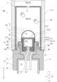
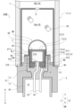
- FIG. 1 is a sectional view showing a state of the gas generator according to the first embodiment before operation.
- FIG. 2 is a cross-sectional view showing the vicinity of the igniter assembly before the gas generator according to the first embodiment is activated.
- FIG. 3 is a top view of the inner cup of the cup body according to the first embodiment.
- FIG. 4 is a cross-sectional view showing a state around the igniter assembly when the gas generator according to the first embodiment operates and the ignition part ruptures.
- FIG. 5 is a cross-sectional view showing a state around the igniter assembly when the gas generator according to the first embodiment is activated and the cover member is torn.
- FIG. 6 is a cross-sectional view showing the vicinity of the igniter assembly before the gas generator according to Modification 1 of Embodiment 1 is operated.
- FIG. 7 is a sectional view showing a state around the igniter assembly when the gas generator according to Modification 1 of Embodiment 1 operates and the cover member ruptures.
- FIG. 8 is a sectional view showing a state around the igniter assembly before the gas generator according to the second modification of the first embodiment is operated.
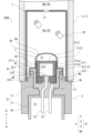
- FIG. 9 is a sectional view showing a state around the igniter assembly before the gas generator according to the second embodiment is activated.
- FIG. 1 is a sectional view showing a state before operation of an airbag gas generator (hereinafter simply referred to as a gas generator) 100 according to a first embodiment.
- FIG. 1 shows a cross section of the housing designated by reference numeral 1 along the axial direction.
- the gas generator 100 according to this embodiment is configured as a so-called single-type gas generator that includes one igniter.
- the gas generator 100 is also configured as a so-called hybrid type gas generator that uses a gas generating agent and pressurized gas as a gas source.
- the technology according to the present disclosure is not limited to these. That is, the gas generator according to the present disclosure may include a plurality of igniters.
- the gas generator according to the present disclosure may be configured as a so-called pyro-type gas generator that uses only a gas generating agent as a gas source, or a so-called stored-type gas generator that uses only pressurized gas as a gas source. It may also be configured as a gas generator.
- the gas generator 100 includes a cylindrical housing 1 in which an igniter attachment hole 111 is formed, and an igniter assembly 2 attached to the housing 1 so as to close the igniter attachment hole 111. , is provided.
- a housing space 10 is defined by the housing 1 and the igniter assembly 2.
- This accommodation space 10 accommodates a gas generating agent 20 and pressurized gas as a gas source.
- the gas generator 100 further includes a holder 7 disposed in the housing space 10 so as to surround the igniter assembly 2 and the gas generating agent 20.
- the direction along the axial direction of the housing 1 is defined as the vertical direction of the gas generator 100
- the igniter assembly 2 side i.e., the lower side in FIG. 1
- the side that is, the upper side in FIG. 1 and the diffuser section side indicated by reference numeral 12
- the side that is, the upper side in FIG. 1 and the diffuser section side indicated by reference numeral 12
- the gas generator 100 is, for example, an inflator for an airbag, and is a device that supplies an operating gas to the airbag to inflate the airbag (not shown) during operation.
- the gas generator 100 burns the gas generating agent 20 filled in the housing space 10 by operating the igniter 3 included in the igniter assembly 2, and generates combustion gas, which is a combustion product, together with pressurized gas. By discharging to the outside of the housing 1, an airbag (not shown) is inflated.
- Each component of the gas generator 100 will be explained below.
- the housing 1 includes a housing main body portion 11, a diffuser portion 12, and a rupture plate 13 made of metal.
- the housing main body 11 is formed into a cylindrical shape with both ends open.
- An opening at one end (lower end) of the housing main body 11 is formed as an igniter attachment hole 111 for attaching the igniter assembly 2.
- the opening at the other end (upper end) of the housing body portion 11 is formed as a diffuser attachment hole 112 for attaching the diffuser portion 12.
- a filling hole 113 is formed in the side surface of the housing body 11 to communicate the inside and outside of the housing 1 .
- the filling hole 113 is closed by a closing pin 114 in a state in which the pressurized gas is filled into the accommodation space 10 through the filling hole 113 .
- the diffuser portion 12 is formed into a cylindrical shape with a step and a bottom.
- the diffuser section 12 includes a gas discharge section 121 including a closed end thereof, and a fitting section 122 having a diameter larger than the gas discharge section 121 including an open end thereof.
- a gas exhaust hole 14 is formed in the peripheral wall of the gas exhaust section 121 to communicate the inside and outside of the diffuser section 12 .
- the rupture disc 13 is a plate-shaped member that partitions the interior space of the housing body 11 and the interior space of the diffuser section 12.
- the interior space of the housing main body 11 and the interior space of the diffuser section 12 are partitioned by the rupture disc 13, so that the interior space of the diffuser section 12 is maintained at normal pressure.
- the rupture disc 13 is joined to the diffuser part 12 by welding its peripheral edge to the stepped surface of the diffuser part 12 all around.
- the housing space 10 is formed as a space surrounded by the housing main body 11 of the housing 1, the rupture disc 13, and the igniter assembly 2.
- the gas generating agent 20 accommodated in the accommodation space 10 is combusted by operation of the igniter 3 to generate combustion gas.
- the gas generating agent 20 for example, a solid gas generating agent having a relatively low combustion temperature is used.
- the combustion temperature of the gas generating agent 20 is, for example, 1000 to 1700°C.
- the gas generating agent 20 may be, for example, a single-hole cylindrical material made of guanidine nitrate (41% by weight), basic copper nitrate (49% by weight), and a binder or additive.
- the pressurized gas accommodated in the accommodation space 10 may be, for example, a single inert gas such as argon or helium, or a pressurized gas consisting of a mixture thereof.
- the gas generating agent 20 and pressurized gas are not limited to the above.
- a holder 7 for holding the gas generating agent 20 near the igniter assembly 2 is arranged in the housing space 10.
- the holder 7 is a bottomed cylindrical member that extends in the vertical direction and is closed at the upper end, and is arranged to surround the igniter assembly 2 attached to the igniter attachment hole 111.
- the accommodation space 10 is divided into a combustion chamber 10a inside the holder 7 and a pressurized gas chamber 10b outside the holder 7.
- the gas generating agent 20 is placed in a combustion chamber 10a formed around the igniter assembly 2.
- the holder 7 is formed with a communication hole 71 having a size that does not allow the gas generating agent 20 to pass through, and the combustion chamber 10a and the pressurized gas chamber 10b communicate with each other via the communication hole 71. Therefore, pressurized gas exists in both the combustion chamber 10a and the pressurized gas chamber 10b. That is, the entire housing space 10 including the combustion chamber 10a and the pressurized gas chamber 10b is filled with pressurized gas, and the entire housing space 10 is in a pressurized state.
- FIG. 2 is a sectional view showing a state around the igniter assembly 2 before the gas generator 100 according to the first embodiment is activated.
- the igniter assembly 2 includes an igniter 3, a collar member 4, a resin member 5, and a metal cover member 6.
- the igniter 3 includes an ignition part 31 and a pair of conductive pins 32, 32.
- the ignition section 31 is formed with an ignition chamber 314 in which ignition powder is accommodated.
- An ignition current for igniting the ignition charge housed in the ignition chamber 314 is supplied to the pair of conductive pins 32 , 32 .
- the pair of conductive pins 32, 32 are an example of a "conductive part" according to the present disclosure.
- the igniter 3 is configured as an electric igniter. Specifically, when the igniter 3 is actuated by the ignition current supplied to the pair of conductive pins 32, 32, the ignition part 31 is cleaved, and combustion products of the igniter are released. As shown in FIG. 2, the igniter 3 is arranged such that the ignition part 31 is located inside the housing space 10 (closer to the housing space 10) than the pair of conductive pins 32, 32. There is.
- the ignition unit 31 includes a cup body 311, a metal header 312 (an example of a "closure member” according to the present disclosure), and a charge holder 313.
- the cup body 311 is formed into a cylindrical shape with a bottom, and has a double structure in which an insulating outer cup 311b is superimposed on the outer side of a metal inner cup 311a.
- the material of the outer cup 311b is not particularly limited, but a resin material is exemplified. Since the insulating outer cup 311b is interposed between the inner cup and the cover member 6, current supplied to the housing 1 due to electrical leakage can be transferred to the conductive pin via the cover member 6, the inner cup 311a, and the metal header 312.
- the cup body 311 includes a cylindrical peripheral wall 3111 and a lid wall 3112 that closes one end (upper end) of the peripheral wall 3111.
- the lid wall portion 3112 is an example of a “cleavage portion” according to the present disclosure.
- the metal header 312 is a metal member formed in a cylindrical shape, and is arranged inside the cup body 311 so as to close an opening formed at the other end (lower end) of the peripheral wall portion 3111.
- the metal header 312 is welded to the inner wall of the peripheral wall portion 3111 on its outer peripheral surface all the way around. As shown in FIG. 2, the cup body 311 and the metal header 312 define an ignition chamber 314 in which ignition powder is accommodated.
- Charge holder 313 is formed in a cylindrical shape.
- the charge holder 313 is arranged in the ignition chamber 314 so as to surround the ignition powder while facing the peripheral wall 3111 of the cup body 311 and in contact with the peripheral wall 3111.
- Providing the charge holder 313 makes it easier to pressurize, for example, ignition powder into the metal header 312. Further, after the igniter 3 is assembled, it is possible to prevent the state of contact between the ignition charge and the bridge wire 315 described below from changing due to external pressure.
- a pair of conductive pins 32, 32 extend downward from the ignition part 31.
- One of the pair of conductive pins 32 , 32 is inserted into a through hole of the metal header 312 and joined to the metal header 312 via an insulator 316 .
- the other of the pair of conductive pins 32, 32 is joined to the lower surface of the metal header 312.
- a connector (not shown) for supplying power from an external power source is connected to the pair of conductive pins 32, 32.
- the igniter 3 is operated by power supplied to a pair of conductive pins 32, 32 via a connector.
- a bridge wire 315 that is a resistor that electrically connects one of the conductive pins 32 and the metal header 312 is wired at the bottom of the ignition chamber 314 .
- a current flows through the bridge wire 315, and the Joule heat generated in the bridge wire 315 causes the ignition charge in the ignition chamber 314 to burn.
- the lid wall portion 3112 of the cup body 311 ruptures, and combustion products of the ignition charge are released to the outside of the ignition chamber 314.
- FIG. 3 is a top view of the inner cup 311a of the cup body 311 according to the first embodiment.
- the upper end surface (closed end surface) of the inner cup 311a that constitutes the lid wall portion 3112 of the cup body 311 is illustrated.
- a plurality of grooves 3113 are formed in the upper end surface of the inner cup 311a, starting from the center and extending radially.
- the plurality of grooves 3113 extend in the radial direction from the center of the upper end surface of the inner cup 311a.
- eight grooves 3113 are formed at equal angular intervals.
- the technology of the present disclosure is not limited to this.
- the portion of the upper end of the inner cup 311a where the groove 3113 is formed is thinner than the other portions, and therefore is more fragile than the other portions and is more likely to break than the other portions. This makes it easy for the lid wall portion 3112 to split when the igniter 3 is activated.
- the collar member 4 is a metal cylindrical member that is arranged to surround the igniter 3 and supports the igniter 3 via the resin member 5.
- the collar member 4 includes a first portion 41 including the lower end of the collar member 4, a second portion 42 connected to the upper end of the first portion 41 and having a smaller outer diameter than the first portion 41, and a second portion 42 that is connected to the upper end of the first portion 41 and has a smaller outer diameter than the first portion 41.
- the third portion 43 is connected to the upper end of the portion 42 and includes the upper end of the collar member 4, and has a smaller outer diameter than the second portion 42. As a result, a step is formed on the outer periphery of the collar member 4.
- the resin member 5 is a resin member that is disposed between the igniter 3 and the collar member 4 and joins the igniter 3 and the collar member 4 together.
- the resin member 5 is provided so as to fill an annular gap formed between the igniter 3 and the collar member 4.
- the resin member 5 is arranged so that the lid wall portion 3112, which is the portion torn in the ignition portion 31, a part of the peripheral wall portion 3111, and the tips of the pair of conductive pins 32, 32 are exposed from the resin member 5. It covers the igniter 3.
- the resin member 5 covers the inner peripheral surface of the collar member 4 so that a connector insertion space 51, which is a space into which a power supply connector can be inserted, is formed inside the collar member 4. Further, in this example, the resin member 5 covers the upper end surface of the third portion 43 such that its outer peripheral surface is located on the same plane as the outer peripheral surface of the third portion 43 of the collar member 4.
- a dotted line indicated by the symbol B1 in FIG. 2 represents a boundary portion that is a joint portion between the collar member 4 and the resin member 5.
- the boundary portion B1 is formed by the joint surfaces of the collar member 4 and the resin member 5.
- the boundary portion B1 extends from the outside of the housing 1 to the inside.
- a member in which the collar member 4 and the resin member 5 are integrated is referred to as a joined body 21.
- the end of the boundary portion B1 appears on the surface of the joined body 21 as a boundary line between the collar member 4 and the resin member 5.
- the end of the boundary line between the collar member 4 and the resin member 5 that appears inside the housing 1 is indicated by a symbol B11.
- the boundary line B11 is located on the outer peripheral surface of the joined body 21.
- the cover member 6 surrounds the igniter 31 and the resin member 5 so that the igniter 3 and the resin member 5 are sealed against the housing space 10 before the igniter 3 is activated, and ruptures when the igniter 3 is activated.
- It is a metal member constructed as follows.
- the metal material forming the cover member 6 is not particularly limited, and examples thereof include stainless steel, aluminum, iron, and the like.
- the cover member 6 is generally formed into a cylindrical shape with a bottom, and includes an axially extending portion 61, a radially extending portion 62, a peripheral wall facing portion 63, and a lid wall facing portion 64. .
- the axially extending portion 61 is formed into a cylindrical shape extending in the vertical direction.
- the axially extending portion 61 covers the outer circumferential surface of the third portion 43 of the collar member 4 and the outer circumferential surface of the resin member 5 so as to straddle the boundary line B11 between the collar member 4 and the resin member 5.
- the entire circumference is welded to the outer peripheral surface of the portion 43.
- Reference numeral W3 in FIG. 2 indicates a welded portion between the cover member 6 and the collar member 4.
- the cover member 6 and the collar member 4 are continuously welded around the entire circumference at a position exposed to the accommodation space 10, and the welded portion W3 is exposed to pressurized gas.
- the radially extending portion 62 extends radially inward from the upper end of the axially extending portion 61 and covers the upper end surface of the resin member 5 .
- the peripheral wall opposing portion 63 is formed in a cylindrical shape extending upward from the inner end of the radially extending portion 62 and covers the outer peripheral surface of the peripheral wall portion 3111 of the cup body 311. That is, the peripheral wall opposing portion 63 is disposed so as to face the peripheral wall portion 3111 of the cup body 311 and to be in contact with the peripheral wall portion 3111.
- the peripheral wall facing portion 63 does not need to be in contact with the peripheral wall portion 3111 over the entire circumference, and a portion of the peripheral wall facing portion 63 may be in contact with the peripheral wall portion 3111 in the circumferential direction.
- the cover wall opposing portion 64 is formed in a dome shape (semispherical shape) that closes the upper end of the peripheral wall opposing portion 63 and is convex upward (toward the accommodation space 10 side) before the gas generator 100 is operated.
- the lid wall opposing portion 64 faces the lid wall portion 3112 of the cup body 311 and forms a predetermined space S1 between the lid wall portion 3112 and the lid wall portion 3112.
- the lid wall facing portion 64 is formed to have a uniform thickness throughout.
- the cover member 6 When the igniter 3 is activated, the cover member 6 is opened by the cover wall facing portion 64 being split by the pressure of the combustion products of the ignition charge released from the ignition part 31 into the predetermined space S1.
- a groove may be formed in the lid wall facing portion 64 to facilitate suitable cleavage of the lid wall facing portion 64. This groove may be, for example, a groove extending radially from the top of the cover wall facing portion 64 as a starting point. Note that the cover member 6 itself does not have to be torn.
- a hole is not formed in the cover member 6 according to this embodiment, for example, a through hole may be formed in the cover member 6 and the through hole may be closed with a closing member to form a sealed state. In that case, when the igniter 3 is activated, the cover member 6 may be opened by causing the closing member to split due to the pressure of the combustion products.
- the cover member 6 is welded to the collar member 4 all around, so that before the igniter 3 is activated, the igniter 3 surrounded by the cover member 6, the resin member 5, and the predetermined The space S1 is sealed from the accommodation space 10. Therefore, the predetermined space S1 is maintained at normal pressure. Further, the cover member 6 is welded all around to the collar member 4 across the boundary line B11 so that the end of the boundary part B1 between the resin member 5 and the collar member 4 is not exposed to the accommodation space 10. Therefore, before the igniter 3 is activated, the boundary portion B1 is sealed with respect to the accommodation space 10.
- the gas generator 100 can prevent the fluid from flowing into or out of the accommodation space 10 through the gap. Furthermore, in the gas generator 100 according to the present embodiment, since the collar member 4 is welded to the housing 1 all around, the inflow and outflow of fluid through the boundary between the housing 1 and the collar member 4 is also prevented. has been done. As a result, in the gas generator 100 according to the present embodiment, the housing space 10 is maintained airtight with respect to the outside of the gas generator 100 before the igniter 3 is activated.
- the cover member 6 functions as a protector to protect the igniter 3 from the effects of high pressure. If the ignition part 31 of the igniter 3 is exposed to pressurized gas without the cover member 6, the cup body 311 will deform and the bridge wire 315 disposed in the ignition chamber 314 and the ignition charge will be connected to each other. There is a risk that the contact condition will worsen. In such a case, a situation may occur in which the desired ignition performance of the igniter 3 cannot be obtained, or a situation in which the external diagnostic circuit determines that there is an error and the igniter 3 does not operate.
- the gas generator 100 according to the present embodiment can prevent such a situation by including the cover member 6.
- the predetermined space S1 is a space for making it easier to split the lid wall portion 3112 of the cup body 311 when the igniter 3 is activated.
- the lid wall facing portion 64 of the cover member 6 for forming the predetermined space S1 between the lid wall portion 3112 and the lid wall portion 3112 has a rounded dome shape.
- Strength (pressure resistance) against pressurized gas is imparted to the cover wall facing portion 64. Therefore, it is possible to suppress deformation of the cover wall facing portion 64 due to the pressurized gas before the igniter 3 is activated. Further, it is possible to reduce the thickness of the cover wall facing portion 64 so that the cover wall facing portion 64 easily ruptures when the igniter 3 is activated.
- the peripheral wall opposing portion 63 is disposed so as to face the peripheral wall portion 3111 of the cup body 311 and to be in contact with the peripheral wall portion 3111. Further, a cylindrical charge holder 313 is disposed in the ignition chamber 314 so as to face the peripheral wall 3111 and to be in contact with the peripheral wall 3111 . According to this, the peripheral wall opposing portion 63 of the cover member 6 is supported by the peripheral wall portion 3111 of the cup body 311 and the charge holder 313 against the pressurized gas. Thereby, it is possible to suppress deformation of the peripheral wall facing portion 63 due to the pressurized gas before the igniter 3 is activated.
- the cover member 6 is in a state in which the other parts except the cover wall facing part 64 are in contact with and supported by any one of the igniter 3, the collar member 4, and the resin member 5. . Therefore, it is possible to better suppress deformation of the cover member 6 due to the pressurized gas before the igniter 3 is activated.
- the lid wall facing portion of the cover member does not need to be dome-shaped, and the lid wall facing portion may contact the lid wall portion of the cup body.
- the cover wall facing portion may cover the cover wall so that the entire cover member is in contact with any of the igniter, the collar member, and the resin member, and the gap between the cover wall and the cover member is There is no need for space to be secured.
- the peripheral wall opposing portion of the cover member does not need to be in contact with the peripheral wall portion of the cup body.
- the cover member may be in non-contact with the collar member except for the welded portion with the collar member.
- the cover member 6 may not have the peripheral wall facing portion 63 and a dome-shaped lid wall facing portion 64 may be connected to the radially inner end of the radially extending portion 62.
- FIG. 4 is a sectional view showing the state around the igniter assembly 2 when the gas generator 100 according to the first embodiment is activated and the ignition part 31 is ruptured.
- the lid wall 3112 of the cup body 311 ruptures as shown in FIG. released.
- the cover member 6 prevents the lid wall portion 3112 from being obstructed from splitting. This makes the lid wall portion 3112 easy to tear.
- the lid wall facing part 64 of the cover member 6 ruptures, and the combustion products of the ignition charge are released into the combustion chamber 10a of the accommodation space 10.
- a plurality of grooves 3113 are formed in the upper end surface of the inner cup 311a that constitutes the lid wall portion 3112 of the cup body 311, and extend radially from the center thereof. Therefore, the lid wall portion 3112 cleaves into a petal shape starting from its center. At this time, the flow of combustion products released from the ignition part 31 corresponds to the tearing angle ⁇ of the tearing piece of the lid wall portion 3112.
- the tear angle ⁇ can be defined, for example, as the angle of the tear piece with respect to a plane perpendicular to the axial direction of the peripheral wall portion 3111, as shown in FIG.
- the plurality of grooves 3113 are formed such that the tearing angle ⁇ of the tearing piece of the lid wall portion 3112 is equal to or less than a predetermined value. Therefore, as shown in FIG. 4, the combustion products of the igniter are concentratedly released toward the cover member 6 (more specifically, the lid wall facing portion 64). This makes it easier for the cover member 6 to tear.
- the volume of the predetermined space S1 is set to be equal to or less than a predetermined value. This also makes the cover member 6 easy to tear.
- FIG. 5 is a sectional view showing the state around the igniter assembly 2 when the gas generator 100 according to the first embodiment is activated and the cover member 6 is torn.
- the combustion product of the ignition powder is discharged into the combustion chamber 10a of the accommodation space 10, thereby igniting the gas generating agent 20 disposed in the combustion chamber 10a.
- the combustion gas of the gas generating agent 20 flows into the pressurized gas chamber 10b through a communication hole 71 formed in the holder 7.
- the rupture disc 13 shown in FIG. 1 is destroyed.
- the combustion gas generated by combustion of the gas generating agent and the pressurized gas contained in the housing space 10 are discharged to the outside of the gas generator 100 from the gas discharge hole 14 of the diffuser section 12 .
- the airbag is inflated and the occupants of the vehicle are protected from the impact.
- the gas generator 100 includes the housing 1 in which the igniter attachment hole 111 is formed, and is attached to the housing 1 so as to close the igniter attachment hole 111, and a gas source is housed therein.
- an igniter assembly 2 defining, together with the housing 1, a receiving space 10.
- the igniter assembly 2 includes an igniter 3, a metal collar member 4, a resin member 5, and a metal cover member 6.
- the igniter 3 includes an ignition section 31 in which an ignition chamber 314 for accommodating an ignition charge is formed, and a pair of conductive pins 32, 32 to which an ignition current for igniting the ignition charge is supplied.
- the ignition part 31 is arranged so as to be located closer to the inside of the accommodation space 10 than the conductive pins 32, 32.
- the igniter 3 is configured so that the ignition part 31 is ruptured by being activated by the ignition current supplied to the pair of conductive pins 32, 32, and the combustion products of the igniter are released.
- the collar member 4 is formed in a cylindrical shape and is inserted into the igniter attachment hole 111 so as to surround the igniter 3.
- the resin member 5 is disposed between the igniter 3 and the collar member 4, and the lid wall portion 3112, which is the portion that cleaves in the ignition portion 31, and the pair of conductive pins 32, 32 are exposed from the resin member 5. The igniter 3 and the collar member 4 are joined together.
- the cover member 6 surrounds the igniter 31 and the resin member 5 so that the igniter 3 and the resin member 5 are sealed against the housing space 10, and is configured to split when the igniter 3 is activated.
- the cover member 6 is welded to the collar member 4 all around the boundary line B11 between the resin member 5 and the collar member 4. According to the gas generator 100 according to the first embodiment configured in this way, the airtightness of the accommodation space 10 in which the gas source is accommodated can be improved.
- the collar member 4 of the gas generator 100 according to the first embodiment is welded to the housing 1 all around. According to this, the airtightness of the accommodation space 10 can be further improved.
- the cover member 6 of the gas generator 100 is formed so that a predetermined space S1 is secured between the cover member 6 and the cover wall portion 3112 that cleaves at the ignition portion 31. Thereby, the lid wall portion 3112 can be easily split.
- a gas generating agent 20 and pressurized gas are housed in the housing space 10 as gas sources. According to the gas generator 100 in which the airtightness of the housing space 10 is improved as described above, leakage of pressurized gas to the outside of the gas generator 100 can be suppressed.
- the ignition section 31 of the gas generator 100 has a cup body 311 including a cylindrical peripheral wall part 3111 and a lid wall part 3112 that closes one end of the peripheral wall part 3111. Further, the ignition section 31 includes a metal header 312 that is arranged to close an opening formed at the other end of the peripheral wall section 3111 and defines an ignition chamber 314 together with the cup body 311 . Further, the ignition section 31 is configured so that when the igniter 3 is activated, the cover wall section 3112 is split to release combustion products of the ignition charge to the outside of the ignition chamber 314.
- the cover member 6 has a cylindrical peripheral wall opposing portion 63 that is disposed opposite to and in contact with the peripheral wall portion 3111 of the cup body 311, and a cylindrical peripheral wall opposing portion 63 that faces the lid wall portion 3112 of the cup body 311 and faces the housing space 10 side. It has a dome-shaped lid wall facing portion 64 formed to be convex. According to this, the peripheral wall facing part 63 is supported by the peripheral wall part 3111 of the cup body 311 and the pressure resistance of the lid wall facing part 64 is improved, so that the cover member 6 is deformed by the pressurized gas before the igniter 3 is activated. can be suppressed.
- the ignition part 31 of the gas generator 100 further has a cylindrical shape arranged in the ignition chamber 314 so as to surround the ignition charge while facing and in contact with the peripheral wall part 3111 of the cup body 311. It has a charge holder 313. According to this, since the peripheral wall facing portion 63 of the cover member 6 is supported by the peripheral wall portion 3111 of the cup body 311 and the charge holder 313, deformation of the peripheral wall facing portion 63 can be suppressed more suitably.
- the lid wall portion 3112 of the ignition portion 31 is configured such that the combustion products of the ignition charge are concentratedly radiated toward the cover member 6 when the igniter 3 is activated. cleave. Thereby, the cover member 6 can be easily split.
- FIG. 6 is a sectional view showing the state of the vicinity of the igniter assembly 2 before the gas generator 100A according to the first modification of the first embodiment is operated.
- FIG. 7 is a sectional view showing the state around the igniter assembly 2 when the gas generator 100A according to the first modification of the first embodiment operates and the cover member 6A is torn.
- the lid wall portion 3112 of the cup body 311 cleaves so as to come into contact with the cover member 6A when the igniter 3 is activated.
- the cover member 6A secures a predetermined space S1 between the cover member 3112 and the cover wall 3112 before the igniter 3 is activated.
- the tear piece of the lid wall portion 3112 is formed so as to come into contact with the cover member 6A.
- the igniter 3 is activated, the tear piece of the lid wall portion 3112 of the cup body 311 comes into contact with the cover member 6A, so that stress is concentrated on the cover member 6A (the part that the tear piece contacts). Thereby, the cover member 6A can be easily torn apart.
- FIG. 8 is a sectional view showing a state around the igniter assembly 2 before the gas generator 100B according to the second modification of the first embodiment is operated.
- the resin member 5 is arranged so that the upper end surface of the resin member 5 is located on the same plane as the upper end surface of the third portion 43 of the collar member 4. It covers the inner peripheral surface of 4. Therefore, the end of the boundary line B11 between the collar member 4 and the resin member 5 that appears inside the housing 1 is located on the upper end surface of the joined body 21 of the collar member 4 and the resin member 5. Further, the cover member 6B according to Modification 2 does not have the above-mentioned axially extending portion 61.
- the radially extending portion 62 of the cover member 6B covers the upper end surface of the third portion 43 of the collar member 4 and the upper end surface of the resin member 5 so as to straddle the boundary line B11 between the collar member 4 and the resin member 5. It is continuously welded to the upper end surface of the third portion 43 over the entire circumference. Also in the gas generator 100B according to the second modification, the cover member 6B is welded all around to the collar member 4 across the boundary line B11 between the resin member 5 and the collar member 4, so that the housing space is reduced. 10 airtightness can be improved.
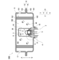
- FIG. 9 is a sectional view showing a state of the gas generator 100C according to the second embodiment before operation.
- FIG. 9 shows a cross section of the housing 1C along the axial direction.
- the gas generator 100C according to the second embodiment is configured as a so-called pyro-type gas generator that uses only a gas generating agent as a gas source.
- differences from the gas generator 100 according to the first embodiment described in FIGS. 1 to 5 will be mainly explained, and detailed descriptions of the same points as the gas generator 100 will be omitted.
- a gas generator 100C according to the second embodiment includes a housing 1C, an igniter assembly 2, a filter 8, and an inner cylinder member 9.
- the gas generator 100C according to the second embodiment includes the igniter assembly 2 shown in FIG. 2, it may include the igniter assembly 2 shown in FIG. 8 instead. good.
- an upper shell 15 and a lower shell 16 made of metal are each formed into a cylindrical shape with a bottom and are joined with their open ends facing each other. By doing so, it is formed into a short cylindrical shape with both axial ends closed.
- the configurations of the upper shell 15 and the lower shell 16 are not limited to this, and known configurations can be used as appropriate.
- the upper shell 15 includes a cylindrical upper cylinder part 151, a top plate part 152 that closes the upper end of the upper cylinder part 151, and a top plate part 152 that extends radially outward from the lower end of the upper cylinder part 151. It has a flange-like joint portion 153.
- the lower shell 16 also includes a cylindrical lower cylinder part 161, a bottom plate part 162 that closes the lower end of the lower cylinder part 161, and a flange-shaped joint extending radially outward from the upper end of the lower cylinder part 161. 163.
- the housing 1C is formed by overlapping the joint portion 153 of the upper shell 15 and the joint portion 163 of the lower shell 16 and joining them by welding or the like.
- a plurality of gas exhaust holes 17 are formed in the upper cylinder part 151 of the upper shell 15 in a line along the circumferential direction, which communicates between the inside and outside of the housing 1C. Before the gas generator 100C is activated, the gas discharge hole 17 is closed with a closing member such as a seal tape (not shown).
- an igniter attachment hole 18 for attaching the igniter assembly 2 is formed in the bottom plate portion 162 of the lower shell 16.
- the igniter assembly 2 is inserted into the igniter mounting hole 18 so as to close the igniter mounting hole 18, and the collar member 4 is attached to the housing 1C (more specifically, the inner wall of the igniter mounting hole 18). It is attached to the housing 1C by welding the entire circumference.
- the filter 8 is a cylindrical member with holes formed therein, and as shown in FIG.
- the igniter assembly 2 is disposed between the igniter assembly 2 and the gas exhaust hole 17 in the closed state.
- an accommodation space 10C in which a gas source is accommodated is formed between the housing 1C, the filter 8, and the igniter assembly 2. More specifically, the accommodation space 10C is formed as a space surrounded by the top plate portion 152 of the upper shell 15, the bottom plate portion 162 of the lower shell 16, the filter 8, and the igniter assembly 2.
- the inner cylindrical member 9 is a bottomed cylindrical member that extends in the vertical direction and is closed at the upper end. arranged to surround it. With the collar member 4 of the igniter assembly 2 fitted into the opening formed at the lower end of the inner cylinder member 9, the collar member 4 and the inner cylinder member 9 are welded all around, so that the inner cylinder member 9 is joined to the igniter assembly 2.
- the housing space 10C is divided by the inner cylinder member 9 into a first combustion chamber 101 inside the inner cylinder member 9 and a second combustion chamber 102 outside the inner cylinder member 9.
- a plurality of communication holes 91 are formed in the inner cylinder member 9 to communicate the inner space (namely, the first combustion chamber 101) and the outer space (namely, the second combustion chamber 102).
- the communication hole 91 is closed by a closing member such as a seal tape (not shown) before the igniter 3 is activated.
- a first gas generating agent 30 is housed in the first combustion chamber 101 as a gas source, and a second gas generating agent 40 is housed in the second combustion chamber 102 as a gas source.
- the first gas generating agent 30 is combusted by the operation of the igniter 3 to generate combustion gas.
- the first gas generating agent 30 functions as a so-called transfer charge for igniting the second gas generating agent 40.
- the second gas generating agent 40 is ignited by the combustion gas of the first gas generating agent 30 (transfer charge) combusted by the operation of the igniter 3, and generates combustion gas.
- the first gas generating agent 30 and the second gas generating agent 40 may be the same as the gas generating agent 20 according to the first embodiment described above.
- first gas generating agent 30 and the second gas generating agent 40 are also not limited to those described above. Further, the first gas generating agent 30 and the second gas generating agent 40 may be gas generating agents of the same type, shape, and size, or may be gas generating agents of different types, shapes, and dimensions. It's okay.
- the filter 8 is configured to allow combustion gas to pass therethrough, and the combustion gas is cooled by passing through the filter 8. At this time, the filter 8 filters the combustion gas by collecting combustion residues of the combustion gas.
- the operation of the igniter 3 is the same as in the first embodiment, so a description thereof will be omitted.
- the ignition part 31 is cleaved and combustion products of the igniter are released.
- the cover member 6 is split by the combustion products released from the ignition part 31, and the combustion products are released into the first combustion chamber 101 of the accommodation space 10.
- the first gas generating agent 30 transfer charge
- combustion gas is generated.
- the combustion gas of the first gas generating agent 30 breaks the sealing tape blocking the communication hole 91 and is released from the communication hole 91 into the second combustion chamber 102 .
- the second gas generating agent 40 is ignited by the combustion gas of the first gas generating agent 30, and the combustion gas of the second gas generating agent 40 is generated.
- the combustion gas in the accommodation space 10C is cooled and filtered by passing through the filter 8, and then breaks the sealing tape blocking the gas discharge hole 17 and is discharged to the outside of the gas generator 100C. This inflates the airbag and protects the occupants of the vehicle from the impact.
- the gas generator 100C according to the second embodiment also achieves the same effects as the first embodiment. That is, since the cover member 6 is welded to the collar member 4 all around the boundary line between the resin member 5 and the collar member 4, the boundary between the resin member 5 and the collar member 4 and the igniter 3 are welded to each other. Moisture can be prevented from entering the housing space 10C through the boundary with the resin member 5. As a result, according to the gas generator 100C according to the second embodiment, the airtightness of the accommodation space 10C can be improved.
- the technology according to the present disclosure is applied to a hybrid-type gas generator or a pyro-type gas generator, but the technology of the present disclosure uses pressurized gas as a gas source.
- the present invention may also be applied to a so-called stored type gas generator using only a gas generator.
- the technology according to the present disclosure may be applied to a gas generator that releases gas by rupturing a rupture disc using a shock wave, such as that disclosed in Japanese Patent Publication No. 2003-520153.
Abstract
La présente invention concerne un générateur de gaz qui comprend : un boîtier ; et un ensemble allumeur qui délimite, conjointement avec le boîtier, un espace de réception pour y recevoir une source de gaz. L'ensemble allumeur comprend : un allumeur ; un élément de couleur ; un élément de résine par lequel l'allumeur et l'élément de couleur sont reliés d'un seul tenant l'un à l'autre ; et un élément de couvercle métallique qui renferme une unité d'allumage et l'élément de résine de façon à sceller de manière étanche l'allumeur et l'élément de résine par rapport à l'espace de réception et qui est configuré de façon à se fendre lorsque l'allumeur est activé. L'ensemble du périmètre de l'élément de couvercle est soudé à l'élément de couleur de façon à couvrir la limite entre l'élément de résine et l'élément de couleur.
Applications Claiming Priority (2)
| Application Number | Priority Date | Filing Date | Title |
|---|---|---|---|
| JP2022-091414 | 2022-06-06 | ||
| JP2022091414 | 2022-06-06 |
Publications (1)
| Publication Number | Publication Date |
|---|---|
| WO2023238766A1 true WO2023238766A1 (fr) | 2023-12-14 |
Family
ID=89118338
Family Applications (1)
| Application Number | Title | Priority Date | Filing Date |
|---|---|---|---|
| PCT/JP2023/020442 WO2023238766A1 (fr) | 2022-06-06 | 2023-06-01 | Générateur de gaz |
Country Status (1)
| Country | Link |
|---|---|
| WO (1) | WO2023238766A1 (fr) |
Citations (8)
| Publication number | Priority date | Publication date | Assignee | Title |
|---|---|---|---|---|
| JPH05505990A (ja) * | 1990-04-05 | 1993-09-02 | アトランティック・リサーチ・コーポレーション | エア・クッション用のインフレータおよびエア・クッション装置 |
| JP2005225346A (ja) * | 2004-02-12 | 2005-08-25 | Daicel Chem Ind Ltd | エアバッグ用インフレータ |
| WO2008153097A1 (fr) * | 2007-06-13 | 2008-12-18 | Nipponkayaku Kabushikikaisha | Amorce, dispositif de génération de gaz pour coussin gonflable et dispositif de génération de gaz pour prétendeur de ceinture de sécurité |
| US20110018243A1 (en) * | 2009-05-11 | 2011-01-27 | Takata-Petri Ag | Gas generator for inflating a gas bag of a vehicle occupant restraint system and method of inflating a gas bag |
| JP2016022946A (ja) * | 2014-07-21 | 2016-02-08 | ティーアールダブリュー・エアバッグ・システムズ・ゲーエムベーハー | 破裂キャップを備えるハイブレッドインフレータ、破裂キャップ、エアバッグモジュール、車の安全システム及び破裂キャップを製造する方法 |
| US20160167618A1 (en) * | 2014-12-10 | 2016-06-16 | Michael P. Jordan | Initiator assemblies |
| US20180141514A1 (en) * | 2016-11-18 | 2018-05-24 | Trw Airbag Systems Gmbh | Hybrid inflator with foam as a fuel |
| JP2019214359A (ja) * | 2018-05-18 | 2019-12-19 | ティーアールダブリュー・エアバッグ・システムズ・ゲーエムベーハー | 管状インフレータのための推進剤ケージ、管状インフレータのためのパッキン要素、エアバッグモジュールのための管状インフレータ、エアバッグモジュール、自動車安全システム、管状インフレータの動作および製造方法 |
-
2023
- 2023-06-01 WO PCT/JP2023/020442 patent/WO2023238766A1/fr unknown
Patent Citations (8)
| Publication number | Priority date | Publication date | Assignee | Title |
|---|---|---|---|---|
| JPH05505990A (ja) * | 1990-04-05 | 1993-09-02 | アトランティック・リサーチ・コーポレーション | エア・クッション用のインフレータおよびエア・クッション装置 |
| JP2005225346A (ja) * | 2004-02-12 | 2005-08-25 | Daicel Chem Ind Ltd | エアバッグ用インフレータ |
| WO2008153097A1 (fr) * | 2007-06-13 | 2008-12-18 | Nipponkayaku Kabushikikaisha | Amorce, dispositif de génération de gaz pour coussin gonflable et dispositif de génération de gaz pour prétendeur de ceinture de sécurité |
| US20110018243A1 (en) * | 2009-05-11 | 2011-01-27 | Takata-Petri Ag | Gas generator for inflating a gas bag of a vehicle occupant restraint system and method of inflating a gas bag |
| JP2016022946A (ja) * | 2014-07-21 | 2016-02-08 | ティーアールダブリュー・エアバッグ・システムズ・ゲーエムベーハー | 破裂キャップを備えるハイブレッドインフレータ、破裂キャップ、エアバッグモジュール、車の安全システム及び破裂キャップを製造する方法 |
| US20160167618A1 (en) * | 2014-12-10 | 2016-06-16 | Michael P. Jordan | Initiator assemblies |
| US20180141514A1 (en) * | 2016-11-18 | 2018-05-24 | Trw Airbag Systems Gmbh | Hybrid inflator with foam as a fuel |
| JP2019214359A (ja) * | 2018-05-18 | 2019-12-19 | ティーアールダブリュー・エアバッグ・システムズ・ゲーエムベーハー | 管状インフレータのための推進剤ケージ、管状インフレータのためのパッキン要素、エアバッグモジュールのための管状インフレータ、エアバッグモジュール、自動車安全システム、管状インフレータの動作および製造方法 |
Similar Documents
| Publication | Publication Date | Title |
|---|---|---|
| US6718884B1 (en) | Initiator assembly | |
| US5621183A (en) | Initiator for an air bag inflator | |
| JP2620052B2 (ja) | 膨張器具の膨張装置 | |
| US7431337B2 (en) | Inflator for an air bag | |
| US5468017A (en) | Auto ignition package for an air bag inflator | |
| JP3038714U (ja) | インフレータ用の内蔵型装薬式起爆装置 | |
| US5821446A (en) | Inflator for an inflatable vehicle occupant protection device | |
| WO2003044445A1 (fr) | Ensemble initiateur | |
| WO2001098114A1 (fr) | Producteur de gaz pour coussin de securite gonflable | |
| JP2004217059A (ja) | ガス発生器 | |
| JPWO2008153097A1 (ja) | スクイブならびにエアバッグ用ガス発生装置およびシートベルトプリテンショナー用ガス発生装置 | |
| JP2006347374A (ja) | エアバッグ用ガス発生器 | |
| JP2017197170A (ja) | ハイブリッドインフレータ、かかるハイブリッドインフレータを備えるエアバッグユニット及び車両の安全システム、並びに衝撃波を形成する方法 | |
| KR0163804B1 (ko) | 자동차 탑승자 구속장치를 팽창시키기 위한 장치 | |
| JP3906910B2 (ja) | イニシエータ | |
| US7600781B2 (en) | Inflator | |
| JP4198063B2 (ja) | 冷ガス発生器 | |
| WO2023238766A1 (fr) | Générateur de gaz | |
| US10308211B2 (en) | Support structure of closing member for gas generator and gas generator using same | |
| WO2022239790A1 (fr) | Ensemble allumeur et dispositif de génération de gaz | |
| JP2000329500A (ja) | スクイブ | |
| WO2022168795A1 (fr) | Ensemble allumeur et générateur de gaz | |
| JP5305991B2 (ja) | 小型ガス発生器 | |
| JP7368325B2 (ja) | ガス発生器 | |
| US20230271586A1 (en) | Igniter assembly and gas generator provided with same |
Legal Events
| Date | Code | Title | Description |
|---|---|---|---|
| 121 | Ep: the epo has been informed by wipo that ep was designated in this application |
Ref document number: 23819746 Country of ref document: EP Kind code of ref document: A1 |