WO2023238754A1 - 伸縮性デバイス - Google Patents
伸縮性デバイス Download PDFInfo
- Publication number
- WO2023238754A1 WO2023238754A1 PCT/JP2023/020308 JP2023020308W WO2023238754A1 WO 2023238754 A1 WO2023238754 A1 WO 2023238754A1 JP 2023020308 W JP2023020308 W JP 2023020308W WO 2023238754 A1 WO2023238754 A1 WO 2023238754A1
- Authority
- WO
- WIPO (PCT)
- Prior art keywords
- stretchable
- cover layer
- base material
- discontinuous region
- layer
- Prior art date
- Legal status (The legal status is an assumption and is not a legal conclusion. Google has not performed a legal analysis and makes no representation as to the accuracy of the status listed.)
- Ceased
Links
Images





Classifications
-
- H—ELECTRICITY
- H05—ELECTRIC TECHNIQUES NOT OTHERWISE PROVIDED FOR
- H05K—PRINTED CIRCUITS; CASINGS OR CONSTRUCTIONAL DETAILS OF ELECTRIC APPARATUS; MANUFACTURE OF ASSEMBLAGES OF ELECTRICAL COMPONENTS
- H05K3/00—Apparatus or processes for manufacturing printed circuits
- H05K3/22—Secondary treatment of printed circuits
- H05K3/28—Applying non-metallic protective coatings
-
- B—PERFORMING OPERATIONS; TRANSPORTING
- B32—LAYERED PRODUCTS
- B32B—LAYERED PRODUCTS, i.e. PRODUCTS BUILT-UP OF STRATA OF FLAT OR NON-FLAT, e.g. CELLULAR OR HONEYCOMB, FORM
- B32B7/00—Layered products characterised by the relation between layers; Layered products characterised by the relative orientation of features between layers, or by the relative values of a measurable parameter between layers, i.e. products comprising layers having different physical, chemical or physicochemical properties; Layered products characterised by the interconnection of layers
- B32B7/02—Physical, chemical or physicochemical properties
- B32B7/022—Mechanical properties
-
- H—ELECTRICITY
- H05—ELECTRIC TECHNIQUES NOT OTHERWISE PROVIDED FOR
- H05K—PRINTED CIRCUITS; CASINGS OR CONSTRUCTIONAL DETAILS OF ELECTRIC APPARATUS; MANUFACTURE OF ASSEMBLAGES OF ELECTRICAL COMPONENTS
- H05K1/00—Printed circuits
- H05K1/02—Details
-
- H—ELECTRICITY
- H05—ELECTRIC TECHNIQUES NOT OTHERWISE PROVIDED FOR
- H05K—PRINTED CIRCUITS; CASINGS OR CONSTRUCTIONAL DETAILS OF ELECTRIC APPARATUS; MANUFACTURE OF ASSEMBLAGES OF ELECTRICAL COMPONENTS
- H05K1/00—Printed circuits
- H05K1/02—Details
- H05K1/0277—Bendability or stretchability details
- H05K1/0283—Stretchable printed circuits
Definitions
- the present invention relates to a stretchable device.
- Stretchable devices in which stretchable wiring is mounted on a stretchable base material have been known for some time. This stretchable device can be used by being worn on the human body.
- a stretchable device includes a stretchable base material, a stretchable wiring arranged on one main surface of the stretchable base material, a stretchable cover that covers one main surface of the stretchable base material and the stretchable wiring, and a stretchable wire arranged on one main surface of the stretchable base material.
- an adhesive layer provided between the elastic base material and the elastic cover.
- the adhesive layer may be present on one side of the opening in the substrate and the adhesive layer may be absent on the other side. not exist. Therefore, a portion of the stretchable base material (specifically, the inner side surface) forming the opening of the stretchable base material may be exposed. Therefore, although ventilation may be improved by the openings in the stretchable base material, there is a risk that moisture may infiltrate the wiring through the exposed portion of the stretchable base material.
- an object of the present invention is to provide a stretchable device that can improve air permeability and prevent moisture from entering the wiring.
- a stretchable base material having a first main surface and a second main surface, a stretchable wiring provided on the first main surface, and a first cover layer covering the first main surface and the stretchable wiring; a second cover layer covering the second main surface;
- a stretchable device is provided, wherein at least the stretchable substrate is provided with a non-continuous region, and the first cover layer and the second cover layer interconnect at the non-continuous region.
- the stretchable device it is possible to improve air permeability and prevent moisture from penetrating into the inside of the substrate.
- FIG. 1 is a plan view schematically showing a stretchable device according to a first embodiment of the present invention.
- FIG. 2 is a partial cross-sectional view (corresponding to the cross-sectional view taken along line II-II in FIG. 1) schematically showing the stretchable device according to the first embodiment of the present invention.
- FIG. 3 is a partial cross-sectional view schematically showing a stretchable device according to a second embodiment of the present invention.
- FIG. 4 is a partial cross-sectional view schematically showing Modification 1 of the stretchable device according to the second embodiment of the present invention.
- FIG. 5 is a partial sectional view schematically showing a second modification of the stretchable device according to the second embodiment of the present invention.
- FIG. 6 is a partial cross-sectional view schematically showing a stretchable device according to a third embodiment of the present invention.
- FIG. 7 is a partial cross-sectional view schematically showing another example of the stretchable device according to the third embodiment of the present invention.
- FIG. 8 is a partial cross-sectional view schematically showing Modification 1 of the stretchable device according to the third embodiment of the present invention.
- FIG. 9 is a partially enlarged sectional view of FIG. 8.
- FIG. 10 is a partial sectional view schematically showing a second modification of the stretchable device according to the third embodiment of the present invention.
- FIG. 11 is a partially enlarged sectional view of FIG. 10.
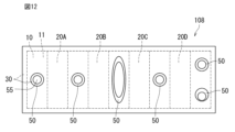
- FIG. 12 is a plan view schematically showing a stretchable device according to a fourth embodiment of the present invention.
- FIG. 12 is a plan view schematically showing a stretchable device according to a fourth embodiment of the present invention.
- FIG. 13 is a schematic plan view of the method for manufacturing a stretchable device (substrate preparation step) according to the first embodiment of the present invention.
- FIG. 14 is a schematic plan view of the method for manufacturing a stretchable device (wiring formation step) according to the first embodiment of the present invention.
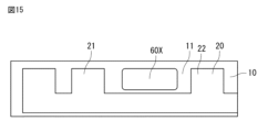
- FIG. 15 is a schematic plan view of the method for manufacturing a stretchable device (step of forming through holes in a base material) according to the first embodiment of the present invention.
- FIG. 16 is a schematic plan view of the method for manufacturing a stretchable device (cover layer arrangement step) according to the first embodiment of the present invention.
- FIG. 1 is a plan view schematically showing a stretchable device according to a first embodiment of the present invention.
- FIG. 2 is a partial cross-sectional view (corresponding to the cross-sectional view taken along line II-II in FIG. 1) schematically showing the stretchable device according to the first embodiment of the present invention.
- the thickness direction of the stretchable base material described later is indicated by a double-headed arrow X.
- the stretchable device 100 includes a stretchable base material 10, stretchable wiring 20, a first cover layer 30, and a second cover layer 40.
- the stretchable base material 10 has a first main surface 11 and a second main surface 12.
- the stretchable wiring 20 is provided on the first main surface 11 of the stretchable base material 10.
- the first cover layer 30 covers the first main surface 11 of the stretchable base material 10 and the stretchable wiring 20 .
- the second cover layer 40 covers the second main surface 12 of the stretchable base material 10 .
- the stretchable wiring 20 provided on the first main surface 11 of the stretchable base material 10 refers to the stretchable wire in contact with the first main surface 11 of the stretchable base material 10. 20, and a stretchable wiring 20 that is not in direct contact with the first main surface 11 of the stretchable base material 10 but is spaced apart from the first main surface 11 via another member (for example, a resin layer to be described later). .
- the stretchable base material 10 is a sheet-like or film-like stretchable base material, and is made of, for example, a stretchable resin material.
- the resin material of the stretchable base material 10 include thermoplastic polyurethane (TPU), polyethylene (PE), polystyrene (PS), and polyethylene terephthalate (PET).
- the thickness of the stretchable base material 10 is not particularly limited, but from the viewpoint of not inhibiting the expansion and contraction of the surface of a living body when it is attached to a living body, it is preferably 100 ⁇ m or less, and more preferably 50 ⁇ m or less. Further, the thickness of the stretchable base material 1 is preferably 20 ⁇ m or more from the viewpoint of ensuring a predetermined strength.
- the stretchable wiring 20 includes conductive particles and resin.
- Examples of the stretchable wiring 20 include a mixture of metal powder such as Ag, Cu, and Ni as conductive particles and an elastomer resin such as silicone resin.
- the average particle size of the conductive particles is not particularly limited, it is preferably 0.01 ⁇ m or more and 10 ⁇ m or less. Further, the shape of the conductive particles is preferably spherical.
- the thickness of the stretchable wiring 20 is not particularly limited, but is preferably 100 ⁇ m or less, more preferably 50 ⁇ m or less. Moreover, it is preferable that the thickness of the stretchable wiring 20 is 0.01 ⁇ m or more.
- the line width of the stretchable wiring 20 is not particularly limited, it is preferably 0.1 ⁇ m or more, and more preferably 10 mm or less.
- the shape and number of stretchable wiring 2 are not particularly limited.
- the first cover layer 30 and the second cover layer 40 may be formed from a stretchable resin material.
- the first cover layer 30 and the second cover layer 40 are formed of an ionomer resin, a polyester resin, a styrene resin, an olefin resin, an epoxy resin, a urethane resin, an acrylic resin, or a silicone resin. , preferably made of urethane resin.
- the urethane resin include thermoplastic polyurethane (TPU).
- TPU thermoplastic polyurethane
- SBS styrene-butadiene-styrene copolymer resin
- the first cover layer 30 and the second cover 40 may be made of different materials, but are preferably made of the same material. Since the first cover layer 30 and the second cover layer 40 are formed of the same material, there is no difference in expansion and contraction due to tension, heat, etc. between the first cover layer 30 and the second cover layer 40, and there is no bias in distortion. It is possible to suppress the decrease in reliability caused by Furthermore, since the same type of materials are bonded together, the layers are more compatible with each other and the adhesive strength is improved.
- first cover layer 30 does not necessarily need to contact the stretchable wiring 2 and the first main surface 11 of the stretchable base material 10.
- the second cover layer 40 does not necessarily need to contact the second main surface 12 of the stretchable base material 10 .
- the base material 10 is provided with a discontinuous region 60. That is, the base material 10 forms a discontinuous region 60.
- the first embodiment is characterized in that the first cover layer 30 and the second cover layer 40 are connected to each other in this discontinuous region 60.
- the connecting portion 50 of the first cover layer 30 and the second cover layer 40 that are connected to each other covers the contour portion 61 of the discontinuous region 60.
- the connecting portion 50 between the first cover layer 30 and the second cover layer 40 having a laminated structure covers the inner side surface 14 of the base material 10 forming the discontinuous region 60 .
- the stretchable wiring 20 is continuous on the first main surface 11.
- a connecting portion 50 between the first cover layer 30 and the second cover layer 40 is positioned between the first portion 21 of the stretchable wiring 20 and the second portion 22 that faces the first portion 21 at a distance (FIG. and Figure 2).
- the single connection portion 50 composed of the first cover layer 30 and the second cover layer 40 is assumed to be continuous in a circumferential manner.
- two or more of the connecting portions 50 may be positioned adjacently. That is, two or more discontinuous regions 60 provided on the base material 10 can be positioned adjacently.
- the first cover layer 30 and the second cover layer are formed inside the contour portion 61 of the discontinuous region 60 based on the position of the contour portion 61.
- Forty connecting portions 50 may be located. Specifically, the end surface 51 of the connecting portion 50 is located inside the contour portion 61 with respect to the position of the contour portion 61 as a reference. In other words, the contour portion 61 of the discontinuous region 60 is located outside the end surface 51 of the connecting portion 50 with respect to the position of the connecting portion 50 .
- the first cover layer 30 and the second cover layer 40 overlap in a part of the discontinuous region 60 described above. Specifically, when viewed from the thickness direction overlap along the contoured surface.
- the connecting portion 50 in the discontinuous region 60 due to the presence of the connecting portion 50 in the discontinuous region 60, the outline portion 61 of the discontinuous region 60 of the elastic base material 10, specifically, the inner side surface of the base material 10 forming the discontinuous region 60. 14 exposure can be suppressed. Thereby, it is possible to suppress moisture from entering the stretchable wiring 20 from the outside.
- the connection reliability of the stretchable wiring 20 can be improved.
- the base material 10 is not present in the discontinuous region 60, the air permeability in the discontinuous region 60 can be improved compared to other continuous regions of the base material 10. Thereby, the breathability of the stretchable device 100 can be improved as a whole.
- the stretchable device 100 of the first embodiment it is possible to improve breathability as a whole and prevent moisture from entering the stretchable wiring 20 from the outside.
- the first cover layer 30 and the second cover layer 40 overlap in a part of the discontinuous region 60 when viewed from the thickness direction X of the stretchable base material 10. That is, the connecting portion 50 between the first cover layer 30 and the second cover layer 40 is located in a part of the discontinuous region 60.
- the connecting portion 50 is not located in the remaining portion of the discontinuous region 60, but the through hole 55 that penetrates the first cover layer 30 and the second cover layer 40 is located. Since the through hole 55 is a physical gap, the breathability of the stretchable device 100 can be further improved.
- connection surface 52 (or contact surface) where the first cover layer 30 and the second cover layer 40 are connected to each other in the thickness direction It is preferable that the discontinuous region 60 overlaps with the inner side of the discontinuous region 60 .
- the inner side surface 14 of the stretchable substrate 10 forming the discontinuous region 60 can restrain the connecting surface 52 from moving from one discontinuous region 60 to another region. This makes it possible to improve the reliability of the connection.
- the connecting surface 52 may be disposed between both main surfaces of the stretchable base material 10 in cross-sectional view. It is envisioned that the stretchable device 100 will stretch and contract from side to side when in use. At this time, if the connection surface 52 is not between the two main surfaces of the elastic base material 10 in the thickness direction X of the elastic base material 10, the connection surface will move from side to side, reducing the reliability of the connection surface 52 There is a possibility that it will decrease. Further, when the connection surface 52 is flush with the upper main surface of the elastic base material 10, movement of the lower second cover layer 40 can be suppressed, but movement of the upper first cover layer 30 is difficult to suppress. , it may be difficult to improve connection reliability. With the above-mentioned more preferable structure, movement of the connecting surface 52 from the discontinuous region 60 to another region is further suppressed by the inner side surface 14 of the stretchable base material. This makes it possible to further improve the reliability of the connection.
- each of the first cover layer 30 and the second cover layer 40 is composed of the stretchable base material 10 alone or the stretchable base material 10 and the stretchable base material 10. It is preferable that the elastic wiring base material has higher moisture permeability (equivalent to water vapor permeability) than the stretchable wiring base material including the elastic wiring 20.
- the moisture permeability of each of the first cover layer 30 and the second cover layer 40 is greater than 100 g/(m 2 ⁇ 24 h) and 150 g/ ( m2 ⁇ 24h) or more, 200g/( m2 ⁇ 24h) or more, 250g/( m2 ⁇ 24h) or more, 300g/( m2 ⁇ 24h) or more, 350g/( m2 ⁇ 24h) or more, or 400g /( m2 ⁇ 24h) or more.
- the moisture permeability of each of the first cover layer 30 and the second cover layer 40 may be 250 g/(m 2 ⁇ 24 h).
- the elastic modulus of each of the first cover layer 30 and the second cover layer 40 is preferably smaller than the elastic modulus of the stretchable base material 1. Since the stretchable device 100 can stretch and contract during use, if a cover layer with a high elastic modulus is used, the stretchable device 100 may cause discomfort to the human body when it stretches. By making the elastic modulus of these cover layers smaller than the elastic modulus of the elastic base material 10, it is possible to reduce the discomfort felt by the user when using the elastic device 100.
- the elastic modulus of each of the first cover layer 30 and the second cover layer 40 is 1.0 ⁇ 10 ⁇ 6 Pa or more from the viewpoint of preventing inhibition of expansion and contraction during expansion and contraction, and 1.0 ⁇ 10 Pa from the viewpoint of suppressing deformation. It is preferable that it is 8 Pa or less.
- the method for measuring the elastic modulus is not particularly limited, and includes, for example, dynamic viscoelasticity measurement.
- the elastic modulus can be calculated by measuring in the same manner and comparing the average values.
- each of the first cover layer 30 and the second cover layer 40 is preferably 30 ⁇ m or more from the viewpoint of suppressing moisture intrusion, that is, waterproofing, and preferably 200 ⁇ m or less from the viewpoint of preventing expansion and contraction inhibition during expansion and contraction.
- the thickness of the connecting portion 50 made of the two cover layers 30 and 40 may be greater than the thickness of the elastic base material 10.
- the thickness of the connecting portion 50 made of the two cover layers 30 and 40 may be smaller than the thickness of the stretchable base material 10.
- the base material 10 is prepared (see FIG. 13). After preparing the base material 10, a continuous stretchable wiring 20 is formed on the first main surface 11 of the base material 10 (see FIG. 14). After the stretchable wiring 20 is formed, a predetermined portion of the base material 20 located between the first portion 21 of the stretchable wiring 20 in a continuous form and the second portion 22 facing away from the first portion 21 is A through hole 60X (also referred to as an opening) is formed in the opposite direction (see FIG. 15).
- a through hole 60X also referred to as an opening
- the first cover layer 30 is arranged to cover the first main surface 11 and the stretchable wiring 20 of the base material 10 with the through hole 60X, and and arranging a second cover layer so as to cover the second main surface.
- a through hole 55 is further formed in the connection portion between the first cover layer 30 and the second cover layer 40, which are arranged so as to close the through hole 60X of the base material.
- the stretchable device 100 according to the first embodiment (corresponding to the basic embodiment) can be manufactured.
- FIG. 3 is a partial cross-sectional view schematically showing a stretchable device according to a second embodiment of the present invention.
- the resin layer 70 may be located between the first main surface 11 of the stretchable base material 10 and the stretchable wiring 20.
- the resin layer 70 can be located between the first main surface 11 of the stretchable base material 10 and the stretchable wiring 20, so that the resin layer 70 can be located between the first main surface 11 of the stretchable base material 10 and the stretchable wiring 20.
- the surface can be in contact with the resin layer 70.
- Modification 1 of the second embodiment differs from the form shown in FIG. 3 in that the stretchable device 102 further includes an adhesive layer 80.
- An adhesive layer 80 may be placed in the area. Furthermore, in the thickness direction A layer 80 may be disposed.
- the adhesive layer 80 may be composed of a pressure-sensitive adhesive or the like.
- the pressure-sensitive adhesive is not particularly limited as long as it can be laminated on the elastic base material 10 and generally used.
- the pressure-sensitive adhesive rubber-based, acrylic-based, or silicone-based adhesives can be used.
- each cover layer 30, 40 and the other member can be bonded at a relatively low temperature, thereby preventing deterioration and distortion of the elastic base material 10 due to the use of excessive heat or UV energy. can do.
- the resin layer 70a may be positioned to cover the first main surface 11 of the elastic base material 10 and the elastic wiring 20 provided on the first main surface 11. In this case, the resin layer 70a may be arranged to entirely cover the outer surface of the stretchable wiring 2.
- the resin layer 70a in addition to the stretchable base material 10 can also constitute the contour portion 61 of the discontinuous region 60
- the inner side surface 71a of the resin layer 70a also forms the first cover layer 30 and the second cover layer 40 forming the laminated structure. is covered by a connecting portion 50 of.
- the resin layer 70a is in contact with the first main surface 11 of the stretchable base material 10 except for the location where the wiring 20 is arranged. From the above, it is possible to suppress moisture from entering the stretchable wiring 20 more appropriately than in the first embodiment which does not include the resin layer 70a.
- the thickness of the resin layer 70 is not particularly limited, but is preferably 100 ⁇ m or less, more preferably 50 ⁇ m or less, from the viewpoint of not inhibiting the expansion and contraction of the surface of the living body when it is attached to the living body. Further, the thickness of the resin layer 70 is preferably 10 ⁇ m or more from the viewpoint of ensuring a predetermined strength.
- the total thickness of the base material 10 and the resin layer 70 is preferably 200 ⁇ m or less, more preferably 100 ⁇ m or less. Further, the total thickness of the base material 10 and the resin layer 70 is preferably 30 ⁇ m or more from the viewpoint of ensuring a predetermined strength.
- the first cover layer 30 and the second cover layer 40 have a predetermined water vapor permeability. Therefore, even if the connecting portion 50 between the first cover layer 30 and the second cover layer 40 fills the entire discontinuous region 60 (corresponding to the opening of the stretchable base material 10), there is no discontinuous region 60. That is, the breathability can be improved compared to the case where the stretchable base material 10 has no openings. Compared to the case where the cover layer has openings, the reliability of the stretchable device is improved because the adhesive force between the upper and lower cover layers is improved.
- FIG. 8 is a partial sectional view schematically showing Modification 1 of the stretchable device according to the third embodiment of the present invention.
- FIG. 9 is a partially enlarged sectional view of FIG. 8.
- a step structure is provided by the inner side surface 14 (corresponding to the end surface) of the elastic base material 10 and the inner side surface 71 (corresponding to the end surface) of the resin layer 70.
- the inner side surface of the stretchable base material 10 may be located inside the inner side surface of the resin layer 70 with respect to the position of the inner side surface of the resin layer 70.
- the region of the stretchable base material 10 that does not overlap with the resin layer 70 when viewed from the thickness direction comes into contact with the first cover layer 30 and/or the second cover layer 40 that are the constituent elements of the connection portion 50. are doing.
- the inner side surface of the stretchable base material 10 is made of resin based on the position of the inner side surface of the resin layer 70. It may be located outside the inner side of layer 70. In other words, the region of the resin layer 70 that does not overlap with the stretchable base material 10 when viewed from the thickness direction comes into contact with the first cover layer 30 and/or the second cover layer 40 that are the constituent elements of the connection portion 50. are doing.
- the inner side surface 71b of the resin layer can suppress large movement of the connection surface 52 from the discontinuous region 60 to another region. Note that even in a structure in which the inner side surface of the resin layer does not hang downward, the same effect of suppressing movement of the connecting surface 52 can be provided by the inner side surface.
- the stretchable wire and the first The cover layer 30 and the connecting portion 50 of the second cover layer may be arranged alternately.
- the discontinuous region further includes a resin layer between the first main surface of the stretchable base material and the stretchable wiring or covering the first main surface and the stretchable wire, and the discontinuous region is connected to the stretchable base material and the stretchable wire.
- the stretchable device according to any one of ⁇ 1> to ⁇ 8> which is provided by a resin layer.
- ⁇ 10> The stretchable device according to any one of ⁇ 1> to ⁇ 9>, wherein a stepped structure is provided by the inner side surface of the stretchable base material and the inner side surface of the resin layer.
- ⁇ 11> The stretchable device according to ⁇ 10>, wherein the inner side surface of the stretchable base material is located inside the inner side surface of the resin layer.
Landscapes
- Engineering & Computer Science (AREA)
- Microelectronics & Electronic Packaging (AREA)
- Manufacturing & Machinery (AREA)
- Mechanical Engineering (AREA)
- Structure Of Printed Boards (AREA)
- Laminated Bodies (AREA)
Priority Applications (3)
| Application Number | Priority Date | Filing Date | Title |
|---|---|---|---|
| JP2024526402A JPWO2023238754A1 (https=) | 2022-06-08 | 2023-05-31 | |
| CN202380045075.9A CN119318210A (zh) | 2022-06-08 | 2023-05-31 | 伸缩性器件 |
| US18/955,173 US20250089177A1 (en) | 2022-06-08 | 2024-11-21 | Stretchable device |
Applications Claiming Priority (2)
| Application Number | Priority Date | Filing Date | Title |
|---|---|---|---|
| JP2022093265 | 2022-06-08 | ||
| JP2022-093265 | 2022-06-08 |
Related Child Applications (1)
| Application Number | Title | Priority Date | Filing Date |
|---|---|---|---|
| US18/955,173 Continuation US20250089177A1 (en) | 2022-06-08 | 2024-11-21 | Stretchable device |
Publications (1)
| Publication Number | Publication Date |
|---|---|
| WO2023238754A1 true WO2023238754A1 (ja) | 2023-12-14 |
Family
ID=89118366
Family Applications (1)
| Application Number | Title | Priority Date | Filing Date |
|---|---|---|---|
| PCT/JP2023/020308 Ceased WO2023238754A1 (ja) | 2022-06-08 | 2023-05-31 | 伸縮性デバイス |
Country Status (4)
| Country | Link |
|---|---|
| US (1) | US20250089177A1 (https=) |
| JP (1) | JPWO2023238754A1 (https=) |
| CN (1) | CN119318210A (https=) |
| WO (1) | WO2023238754A1 (https=) |
Cited By (2)
| Publication number | Priority date | Publication date | Assignee | Title |
|---|---|---|---|---|
| WO2025173748A1 (ja) * | 2024-02-14 | 2025-08-21 | 株式会社村田製作所 | 伸縮性デバイス |
| WO2026048693A1 (ja) * | 2024-08-27 | 2026-03-05 | 株式会社村田製作所 | 伸縮性デバイス |
Citations (7)
| Publication number | Priority date | Publication date | Assignee | Title |
|---|---|---|---|---|
| JP2004319962A (ja) * | 2002-12-13 | 2004-11-11 | Victor Co Of Japan Ltd | フレックスリジッドプリント配線板及びその製造方法 |
| JP2008244062A (ja) * | 2007-03-27 | 2008-10-09 | Kojima Press Co Ltd | 回路基板 |
| US20120106095A1 (en) * | 2010-10-29 | 2012-05-03 | Palo Alto Research Center Incorporated | Stretchable electronics modules and circuits |
| JP2012204396A (ja) * | 2011-03-23 | 2012-10-22 | Fujikura Ltd | フレキシブルプリント基板及びその製造方法 |
| JP2020510998A (ja) * | 2017-02-16 | 2020-04-09 | ネーデルランドセ・オルガニサティ・フォール・トゥーヘパスト−ナトゥールウェテンスハッペライク・オンデルズーク・テーエヌオー | フレキシブル回路における渦巻き相互接続 |
| WO2020262288A1 (ja) * | 2019-06-27 | 2020-12-30 | パナソニックIpマネジメント株式会社 | 伸縮性回路基板、及び伸縮性回路実装品 |
| WO2021235282A1 (ja) * | 2020-05-21 | 2021-11-25 | 株式会社村田製作所 | 伸縮性配線基板 |
-
2023
- 2023-05-31 CN CN202380045075.9A patent/CN119318210A/zh active Pending
- 2023-05-31 WO PCT/JP2023/020308 patent/WO2023238754A1/ja not_active Ceased
- 2023-05-31 JP JP2024526402A patent/JPWO2023238754A1/ja active Pending
-
2024
- 2024-11-21 US US18/955,173 patent/US20250089177A1/en active Pending
Patent Citations (7)
| Publication number | Priority date | Publication date | Assignee | Title |
|---|---|---|---|---|
| JP2004319962A (ja) * | 2002-12-13 | 2004-11-11 | Victor Co Of Japan Ltd | フレックスリジッドプリント配線板及びその製造方法 |
| JP2008244062A (ja) * | 2007-03-27 | 2008-10-09 | Kojima Press Co Ltd | 回路基板 |
| US20120106095A1 (en) * | 2010-10-29 | 2012-05-03 | Palo Alto Research Center Incorporated | Stretchable electronics modules and circuits |
| JP2012204396A (ja) * | 2011-03-23 | 2012-10-22 | Fujikura Ltd | フレキシブルプリント基板及びその製造方法 |
| JP2020510998A (ja) * | 2017-02-16 | 2020-04-09 | ネーデルランドセ・オルガニサティ・フォール・トゥーヘパスト−ナトゥールウェテンスハッペライク・オンデルズーク・テーエヌオー | フレキシブル回路における渦巻き相互接続 |
| WO2020262288A1 (ja) * | 2019-06-27 | 2020-12-30 | パナソニックIpマネジメント株式会社 | 伸縮性回路基板、及び伸縮性回路実装品 |
| WO2021235282A1 (ja) * | 2020-05-21 | 2021-11-25 | 株式会社村田製作所 | 伸縮性配線基板 |
Cited By (2)
| Publication number | Priority date | Publication date | Assignee | Title |
|---|---|---|---|---|
| WO2025173748A1 (ja) * | 2024-02-14 | 2025-08-21 | 株式会社村田製作所 | 伸縮性デバイス |
| WO2026048693A1 (ja) * | 2024-08-27 | 2026-03-05 | 株式会社村田製作所 | 伸縮性デバイス |
Also Published As
| Publication number | Publication date |
|---|---|
| JPWO2023238754A1 (https=) | 2023-12-14 |
| CN119318210A (zh) | 2025-01-14 |
| US20250089177A1 (en) | 2025-03-13 |
Similar Documents
| Publication | Publication Date | Title |
|---|---|---|
| WO2023238754A1 (ja) | 伸縮性デバイス | |
| US20180027661A1 (en) | Stretchable circuit board | |
| WO2013190884A1 (ja) | タッチパネル、タッチパネルの製造方法 | |
| JP2005527968A5 (https=) | ||
| JP2021063786A (ja) | 検出装置 | |
| JPWO2023238754A5 (https=) | ||
| JP7464200B2 (ja) | 伸縮性配線基板 | |
| JP6870790B2 (ja) | 伸縮性配線基板 | |
| JP5297113B2 (ja) | コンタクトプローブの製造方法 | |
| JP7718604B2 (ja) | 伸縮性デバイス | |
| JP7622704B2 (ja) | 伸縮性デバイス | |
| US10618245B2 (en) | Flexible laminated structure and display | |
| WO2023105873A1 (ja) | 伸縮デバイス | |
| WO2023032329A1 (ja) | 伸縮性配線基板 | |
| JP7758216B2 (ja) | 伸縮性デバイス | |
| JP7605343B2 (ja) | 伸縮デバイス | |
| JP7563632B2 (ja) | 伸縮配線基板 | |
| JP5016693B2 (ja) | 接続部材 | |
| TW200731429A (en) | Semiconductor device having improved wire-bonding reliability and method of manufacturing the same | |
| CN111083869A (zh) | 一种显示屏的柔性电路板 | |
| JP7559972B2 (ja) | 伸縮性実装基板 | |
| US20250358930A1 (en) | Stretchable device | |
| JP7653936B2 (ja) | 歪みセンサユニットとその製造方法、及び歪みセンサモジュール | |
| WO2026048693A1 (ja) | 伸縮性デバイス | |
| WO2025033274A1 (ja) | 伸縮性デバイス |
Legal Events
| Date | Code | Title | Description |
|---|---|---|---|
| 121 | Ep: the epo has been informed by wipo that ep was designated in this application |
Ref document number: 23819734 Country of ref document: EP Kind code of ref document: A1 |
|
| WWE | Wipo information: entry into national phase |
Ref document number: 202380045075.9 Country of ref document: CN |
|
| WWE | Wipo information: entry into national phase |
Ref document number: 2024526402 Country of ref document: JP |
|
| NENP | Non-entry into the national phase |
Ref country code: DE |
|
| WWP | Wipo information: published in national office |
Ref document number: 202380045075.9 Country of ref document: CN |
|
| 122 | Ep: pct application non-entry in european phase |
Ref document number: 23819734 Country of ref document: EP Kind code of ref document: A1 |