WO2023238754A1 - Stretchable device - Google Patents
Stretchable device Download PDFInfo
- Publication number
- WO2023238754A1 WO2023238754A1 PCT/JP2023/020308 JP2023020308W WO2023238754A1 WO 2023238754 A1 WO2023238754 A1 WO 2023238754A1 JP 2023020308 W JP2023020308 W JP 2023020308W WO 2023238754 A1 WO2023238754 A1 WO 2023238754A1
- Authority
- WO
- WIPO (PCT)
- Prior art keywords
- stretchable
- cover layer
- base material
- discontinuous region
- layer
- Prior art date
Links
- 239000000463 material Substances 0.000 claims abstract description 163
- 239000010410 layer Substances 0.000 claims description 257
- 229920005989 resin Polymers 0.000 claims description 79
- 239000011347 resin Substances 0.000 claims description 79
- 239000012790 adhesive layer Substances 0.000 claims description 14
- 239000000758 substrate Substances 0.000 claims description 8
- 230000001568 sexual effect Effects 0.000 claims description 2
- 238000012986 modification Methods 0.000 description 21
- 230000004048 modification Effects 0.000 description 21
- 230000008602 contraction Effects 0.000 description 10
- 230000035699 permeability Effects 0.000 description 9
- 238000000034 method Methods 0.000 description 7
- 229920002803 thermoplastic polyurethane Polymers 0.000 description 7
- PPBRXRYQALVLMV-UHFFFAOYSA-N Styrene Chemical compound C=CC1=CC=CC=C1 PPBRXRYQALVLMV-UHFFFAOYSA-N 0.000 description 6
- 238000004519 manufacturing process Methods 0.000 description 6
- 239000002245 particle Substances 0.000 description 5
- 239000004820 Pressure-sensitive adhesive Substances 0.000 description 4
- 239000004433 Thermoplastic polyurethane Substances 0.000 description 4
- -1 polyethylene Polymers 0.000 description 4
- 239000000853 adhesive Substances 0.000 description 3
- 230000001070 adhesive effect Effects 0.000 description 3
- 239000000470 constituent Substances 0.000 description 3
- 230000000694 effects Effects 0.000 description 3
- 229920001971 elastomer Polymers 0.000 description 3
- 238000013508 migration Methods 0.000 description 3
- 230000005012 migration Effects 0.000 description 3
- 229920000139 polyethylene terephthalate Polymers 0.000 description 3
- 239000005020 polyethylene terephthalate Substances 0.000 description 3
- 239000004698 Polyethylene Substances 0.000 description 2
- NIXOWILDQLNWCW-UHFFFAOYSA-N acrylic acid group Chemical group C(C=C)(=O)O NIXOWILDQLNWCW-UHFFFAOYSA-N 0.000 description 2
- 230000015572 biosynthetic process Effects 0.000 description 2
- 239000000806 elastomer Substances 0.000 description 2
- 230000002401 inhibitory effect Effects 0.000 description 2
- 230000005764 inhibitory process Effects 0.000 description 2
- 239000000203 mixture Substances 0.000 description 2
- 230000000149 penetrating effect Effects 0.000 description 2
- 229920000573 polyethylene Polymers 0.000 description 2
- 229920001296 polysiloxane Polymers 0.000 description 2
- 238000012545 processing Methods 0.000 description 2
- 229920002050 silicone resin Polymers 0.000 description 2
- 229920000468 styrene butadiene styrene block copolymer Polymers 0.000 description 2
- XLYOFNOQVPJJNP-UHFFFAOYSA-N water Chemical compound O XLYOFNOQVPJJNP-UHFFFAOYSA-N 0.000 description 2
- RSWGJHLUYNHPMX-UHFFFAOYSA-N Abietic-Saeure Natural products C12CCC(C(C)C)=CC2=CCC2C1(C)CCCC2(C)C(O)=O RSWGJHLUYNHPMX-UHFFFAOYSA-N 0.000 description 1
- 239000004925 Acrylic resin Substances 0.000 description 1
- 229920000178 Acrylic resin Polymers 0.000 description 1
- 239000004593 Epoxy Substances 0.000 description 1
- JOYRKODLDBILNP-UHFFFAOYSA-N Ethyl urethane Chemical compound CCOC(N)=O JOYRKODLDBILNP-UHFFFAOYSA-N 0.000 description 1
- YCKRFDGAMUMZLT-UHFFFAOYSA-N Fluorine atom Chemical compound [F] YCKRFDGAMUMZLT-UHFFFAOYSA-N 0.000 description 1
- 229920000459 Nitrile rubber Polymers 0.000 description 1
- ISWSIDIOOBJBQZ-UHFFFAOYSA-N Phenol Chemical compound OC1=CC=CC=C1 ISWSIDIOOBJBQZ-UHFFFAOYSA-N 0.000 description 1
- 239000004793 Polystyrene Substances 0.000 description 1
- KHPCPRHQVVSZAH-HUOMCSJISA-N Rosin Natural products O(C/C=C/c1ccccc1)[C@H]1[C@H](O)[C@@H](O)[C@@H](O)[C@@H](CO)O1 KHPCPRHQVVSZAH-HUOMCSJISA-N 0.000 description 1
- BZHJMEDXRYGGRV-UHFFFAOYSA-N Vinyl chloride Chemical compound ClC=C BZHJMEDXRYGGRV-UHFFFAOYSA-N 0.000 description 1
- 150000001336 alkenes Chemical class 0.000 description 1
- 150000001408 amides Chemical class 0.000 description 1
- FACXGONDLDSNOE-UHFFFAOYSA-N buta-1,3-diene;styrene Chemical compound C=CC=C.C=CC1=CC=CC=C1.C=CC1=CC=CC=C1 FACXGONDLDSNOE-UHFFFAOYSA-N 0.000 description 1
- 229920002678 cellulose Polymers 0.000 description 1
- 239000001913 cellulose Substances 0.000 description 1
- 229920006026 co-polymeric resin Polymers 0.000 description 1
- 239000011248 coating agent Substances 0.000 description 1
- 238000000576 coating method Methods 0.000 description 1
- 229910052802 copper Inorganic materials 0.000 description 1
- 230000006866 deterioration Effects 0.000 description 1
- 238000006073 displacement reaction Methods 0.000 description 1
- 239000003822 epoxy resin Substances 0.000 description 1
- 150000002148 esters Chemical class 0.000 description 1
- 229910052731 fluorine Inorganic materials 0.000 description 1
- 239000011737 fluorine Substances 0.000 description 1
- 150000003949 imides Chemical class 0.000 description 1
- 229910010272 inorganic material Inorganic materials 0.000 description 1
- 239000011147 inorganic material Substances 0.000 description 1
- 229920000554 ionomer Polymers 0.000 description 1
- 229920000126 latex Polymers 0.000 description 1
- 238000005259 measurement Methods 0.000 description 1
- 239000002184 metal Substances 0.000 description 1
- 229910052751 metal Inorganic materials 0.000 description 1
- 229910052759 nickel Inorganic materials 0.000 description 1
- JRZJOMJEPLMPRA-UHFFFAOYSA-N olefin Natural products CCCCCCCC=C JRZJOMJEPLMPRA-UHFFFAOYSA-N 0.000 description 1
- 229920003207 poly(ethylene-2,6-naphthalate) Polymers 0.000 description 1
- 229920000515 polycarbonate Polymers 0.000 description 1
- 239000004417 polycarbonate Substances 0.000 description 1
- 229920000647 polyepoxide Polymers 0.000 description 1
- 229920000728 polyester Polymers 0.000 description 1
- 229920001225 polyester resin Polymers 0.000 description 1
- 239000004645 polyester resin Substances 0.000 description 1
- 239000011112 polyethylene naphthalate Substances 0.000 description 1
- 229920005672 polyolefin resin Polymers 0.000 description 1
- 239000000843 powder Substances 0.000 description 1
- 238000002360 preparation method Methods 0.000 description 1
- 238000004080 punching Methods 0.000 description 1
- 229910052709 silver Inorganic materials 0.000 description 1
- 238000006467 substitution reaction Methods 0.000 description 1
- KHPCPRHQVVSZAH-UHFFFAOYSA-N trans-cinnamyl beta-D-glucopyranoside Natural products OC1C(O)C(O)C(CO)OC1OCC=CC1=CC=CC=C1 KHPCPRHQVVSZAH-UHFFFAOYSA-N 0.000 description 1
- 238000009423 ventilation Methods 0.000 description 1
- 239000011800 void material Substances 0.000 description 1
- 238000004078 waterproofing Methods 0.000 description 1
Images


Classifications
-
- B—PERFORMING OPERATIONS; TRANSPORTING
- B32—LAYERED PRODUCTS
- B32B—LAYERED PRODUCTS, i.e. PRODUCTS BUILT-UP OF STRATA OF FLAT OR NON-FLAT, e.g. CELLULAR OR HONEYCOMB, FORM
- B32B7/00—Layered products characterised by the relation between layers; Layered products characterised by the relative orientation of features between layers, or by the relative values of a measurable parameter between layers, i.e. products comprising layers having different physical, chemical or physicochemical properties; Layered products characterised by the interconnection of layers
- B32B7/02—Physical, chemical or physicochemical properties
- B32B7/022—Mechanical properties
-
- H—ELECTRICITY
- H05—ELECTRIC TECHNIQUES NOT OTHERWISE PROVIDED FOR
- H05K—PRINTED CIRCUITS; CASINGS OR CONSTRUCTIONAL DETAILS OF ELECTRIC APPARATUS; MANUFACTURE OF ASSEMBLAGES OF ELECTRICAL COMPONENTS
- H05K3/00—Apparatus or processes for manufacturing printed circuits
- H05K3/22—Secondary treatment of printed circuits
- H05K3/28—Applying non-metallic protective coatings
Definitions
- the present invention relates to a stretchable device.
- Stretchable devices in which stretchable wiring is mounted on a stretchable base material have been known for some time. This stretchable device can be used by being worn on the human body.
- a stretchable device includes a stretchable base material, a stretchable wiring arranged on one main surface of the stretchable base material, a stretchable cover that covers one main surface of the stretchable base material and the stretchable wiring, and a stretchable wire arranged on one main surface of the stretchable base material.
- an adhesive layer provided between the elastic base material and the elastic cover.
- the adhesive layer may be present on one side of the opening in the substrate and the adhesive layer may be absent on the other side. not exist. Therefore, a portion of the stretchable base material (specifically, the inner side surface) forming the opening of the stretchable base material may be exposed. Therefore, although ventilation may be improved by the openings in the stretchable base material, there is a risk that moisture may infiltrate the wiring through the exposed portion of the stretchable base material.
- an object of the present invention is to provide a stretchable device that can improve air permeability and prevent moisture from entering the wiring.
- a stretchable base material having a first main surface and a second main surface, a stretchable wiring provided on the first main surface, and a first cover layer covering the first main surface and the stretchable wiring; a second cover layer covering the second main surface;
- a stretchable device is provided, wherein at least the stretchable substrate is provided with a non-continuous region, and the first cover layer and the second cover layer interconnect at the non-continuous region.
- the stretchable device it is possible to improve air permeability and prevent moisture from penetrating into the inside of the substrate.
- FIG. 1 is a plan view schematically showing a stretchable device according to a first embodiment of the present invention.
- FIG. 2 is a partial cross-sectional view (corresponding to the cross-sectional view taken along line II-II in FIG. 1) schematically showing the stretchable device according to the first embodiment of the present invention.
- FIG. 3 is a partial cross-sectional view schematically showing a stretchable device according to a second embodiment of the present invention.
- FIG. 4 is a partial cross-sectional view schematically showing Modification 1 of the stretchable device according to the second embodiment of the present invention.
- FIG. 5 is a partial sectional view schematically showing a second modification of the stretchable device according to the second embodiment of the present invention.
- FIG. 6 is a partial cross-sectional view schematically showing a stretchable device according to a third embodiment of the present invention.
- FIG. 7 is a partial cross-sectional view schematically showing another example of the stretchable device according to the third embodiment of the present invention.
- FIG. 8 is a partial cross-sectional view schematically showing Modification 1 of the stretchable device according to the third embodiment of the present invention.
- FIG. 9 is a partially enlarged sectional view of FIG. 8.
- FIG. 10 is a partial sectional view schematically showing a second modification of the stretchable device according to the third embodiment of the present invention.
- FIG. 11 is a partially enlarged sectional view of FIG. 10.
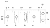
- FIG. 12 is a plan view schematically showing a stretchable device according to a fourth embodiment of the present invention.
- FIG. 12 is a plan view schematically showing a stretchable device according to a fourth embodiment of the present invention.
- FIG. 13 is a schematic plan view of the method for manufacturing a stretchable device (substrate preparation step) according to the first embodiment of the present invention.
- FIG. 14 is a schematic plan view of the method for manufacturing a stretchable device (wiring formation step) according to the first embodiment of the present invention.
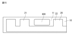
- FIG. 15 is a schematic plan view of the method for manufacturing a stretchable device (step of forming through holes in a base material) according to the first embodiment of the present invention.
- FIG. 16 is a schematic plan view of the method for manufacturing a stretchable device (cover layer arrangement step) according to the first embodiment of the present invention.
- FIG. 1 is a plan view schematically showing a stretchable device according to a first embodiment of the present invention.
- FIG. 2 is a partial cross-sectional view (corresponding to the cross-sectional view taken along line II-II in FIG. 1) schematically showing the stretchable device according to the first embodiment of the present invention.
- the thickness direction of the stretchable base material described later is indicated by a double-headed arrow X.
- the stretchable device 100 includes a stretchable base material 10, stretchable wiring 20, a first cover layer 30, and a second cover layer 40.
- the stretchable base material 10 has a first main surface 11 and a second main surface 12.
- the stretchable wiring 20 is provided on the first main surface 11 of the stretchable base material 10.
- the first cover layer 30 covers the first main surface 11 of the stretchable base material 10 and the stretchable wiring 20 .
- the second cover layer 40 covers the second main surface 12 of the stretchable base material 10 .
- the stretchable wiring 20 provided on the first main surface 11 of the stretchable base material 10 refers to the stretchable wire in contact with the first main surface 11 of the stretchable base material 10. 20, and a stretchable wiring 20 that is not in direct contact with the first main surface 11 of the stretchable base material 10 but is spaced apart from the first main surface 11 via another member (for example, a resin layer to be described later). .
- the stretchable base material 10 is a sheet-like or film-like stretchable base material, and is made of, for example, a stretchable resin material.
- the resin material of the stretchable base material 10 include thermoplastic polyurethane (TPU), polyethylene (PE), polystyrene (PS), and polyethylene terephthalate (PET).
- the thickness of the stretchable base material 10 is not particularly limited, but from the viewpoint of not inhibiting the expansion and contraction of the surface of a living body when it is attached to a living body, it is preferably 100 ⁇ m or less, and more preferably 50 ⁇ m or less. Further, the thickness of the stretchable base material 1 is preferably 20 ⁇ m or more from the viewpoint of ensuring a predetermined strength.
- the stretchable wiring 20 includes conductive particles and resin.
- Examples of the stretchable wiring 20 include a mixture of metal powder such as Ag, Cu, and Ni as conductive particles and an elastomer resin such as silicone resin.
- the average particle size of the conductive particles is not particularly limited, it is preferably 0.01 ⁇ m or more and 10 ⁇ m or less. Further, the shape of the conductive particles is preferably spherical.
- the thickness of the stretchable wiring 20 is not particularly limited, but is preferably 100 ⁇ m or less, more preferably 50 ⁇ m or less. Moreover, it is preferable that the thickness of the stretchable wiring 20 is 0.01 ⁇ m or more.
- the line width of the stretchable wiring 20 is not particularly limited, it is preferably 0.1 ⁇ m or more, and more preferably 10 mm or less.
- the shape and number of stretchable wiring 2 are not particularly limited.
- the first cover layer 30 and the second cover layer 40 may be formed from a stretchable resin material.
- the first cover layer 30 and the second cover layer 40 are formed of an ionomer resin, a polyester resin, a styrene resin, an olefin resin, an epoxy resin, a urethane resin, an acrylic resin, or a silicone resin. , preferably made of urethane resin.
- the urethane resin include thermoplastic polyurethane (TPU).
- TPU thermoplastic polyurethane
- SBS styrene-butadiene-styrene copolymer resin
- the first cover layer 30 and the second cover 40 may be made of different materials, but are preferably made of the same material. Since the first cover layer 30 and the second cover layer 40 are formed of the same material, there is no difference in expansion and contraction due to tension, heat, etc. between the first cover layer 30 and the second cover layer 40, and there is no bias in distortion. It is possible to suppress the decrease in reliability caused by Furthermore, since the same type of materials are bonded together, the layers are more compatible with each other and the adhesive strength is improved.
- first cover layer 30 does not necessarily need to contact the stretchable wiring 2 and the first main surface 11 of the stretchable base material 10.
- the second cover layer 40 does not necessarily need to contact the second main surface 12 of the stretchable base material 10 .
- the base material 10 is provided with a discontinuous region 60. That is, the base material 10 forms a discontinuous region 60.
- the first embodiment is characterized in that the first cover layer 30 and the second cover layer 40 are connected to each other in this discontinuous region 60.
- the connecting portion 50 of the first cover layer 30 and the second cover layer 40 that are connected to each other covers the contour portion 61 of the discontinuous region 60.
- the connecting portion 50 between the first cover layer 30 and the second cover layer 40 having a laminated structure covers the inner side surface 14 of the base material 10 forming the discontinuous region 60 .
- the stretchable wiring 20 is continuous on the first main surface 11.
- a connecting portion 50 between the first cover layer 30 and the second cover layer 40 is positioned between the first portion 21 of the stretchable wiring 20 and the second portion 22 that faces the first portion 21 at a distance (FIG. and Figure 2).
- the single connection portion 50 composed of the first cover layer 30 and the second cover layer 40 is assumed to be continuous in a circumferential manner.
- two or more of the connecting portions 50 may be positioned adjacently. That is, two or more discontinuous regions 60 provided on the base material 10 can be positioned adjacently.
- the first cover layer 30 and the second cover layer are formed inside the contour portion 61 of the discontinuous region 60 based on the position of the contour portion 61.
- Forty connecting portions 50 may be located. Specifically, the end surface 51 of the connecting portion 50 is located inside the contour portion 61 with respect to the position of the contour portion 61 as a reference. In other words, the contour portion 61 of the discontinuous region 60 is located outside the end surface 51 of the connecting portion 50 with respect to the position of the connecting portion 50 .
- the first cover layer 30 and the second cover layer 40 overlap in a part of the discontinuous region 60 described above. Specifically, when viewed from the thickness direction overlap along the contoured surface.
- the connecting portion 50 in the discontinuous region 60 due to the presence of the connecting portion 50 in the discontinuous region 60, the outline portion 61 of the discontinuous region 60 of the elastic base material 10, specifically, the inner side surface of the base material 10 forming the discontinuous region 60. 14 exposure can be suppressed. Thereby, it is possible to suppress moisture from entering the stretchable wiring 20 from the outside.
- the connection reliability of the stretchable wiring 20 can be improved.
- the base material 10 is not present in the discontinuous region 60, the air permeability in the discontinuous region 60 can be improved compared to other continuous regions of the base material 10. Thereby, the breathability of the stretchable device 100 can be improved as a whole.
- the stretchable device 100 of the first embodiment it is possible to improve breathability as a whole and prevent moisture from entering the stretchable wiring 20 from the outside.
- the first cover layer 30 and the second cover layer 40 overlap in a part of the discontinuous region 60 when viewed from the thickness direction X of the stretchable base material 10. That is, the connecting portion 50 between the first cover layer 30 and the second cover layer 40 is located in a part of the discontinuous region 60.
- the connecting portion 50 is not located in the remaining portion of the discontinuous region 60, but the through hole 55 that penetrates the first cover layer 30 and the second cover layer 40 is located. Since the through hole 55 is a physical gap, the breathability of the stretchable device 100 can be further improved.
- connection surface 52 (or contact surface) where the first cover layer 30 and the second cover layer 40 are connected to each other in the thickness direction It is preferable that the discontinuous region 60 overlaps with the inner side of the discontinuous region 60 .
- the inner side surface 14 of the stretchable substrate 10 forming the discontinuous region 60 can restrain the connecting surface 52 from moving from one discontinuous region 60 to another region. This makes it possible to improve the reliability of the connection.
- the connecting surface 52 may be disposed between both main surfaces of the stretchable base material 10 in cross-sectional view. It is envisioned that the stretchable device 100 will stretch and contract from side to side when in use. At this time, if the connection surface 52 is not between the two main surfaces of the elastic base material 10 in the thickness direction X of the elastic base material 10, the connection surface will move from side to side, reducing the reliability of the connection surface 52 There is a possibility that it will decrease. Further, when the connection surface 52 is flush with the upper main surface of the elastic base material 10, movement of the lower second cover layer 40 can be suppressed, but movement of the upper first cover layer 30 is difficult to suppress. , it may be difficult to improve connection reliability. With the above-mentioned more preferable structure, movement of the connecting surface 52 from the discontinuous region 60 to another region is further suppressed by the inner side surface 14 of the stretchable base material. This makes it possible to further improve the reliability of the connection.
- each of the first cover layer 30 and the second cover layer 40 is composed of the stretchable base material 10 alone or the stretchable base material 10 and the stretchable base material 10. It is preferable that the elastic wiring base material has higher moisture permeability (equivalent to water vapor permeability) than the stretchable wiring base material including the elastic wiring 20.
- the moisture permeability of each of the first cover layer 30 and the second cover layer 40 is greater than 100 g/(m 2 ⁇ 24 h) and 150 g/ ( m2 ⁇ 24h) or more, 200g/( m2 ⁇ 24h) or more, 250g/( m2 ⁇ 24h) or more, 300g/( m2 ⁇ 24h) or more, 350g/( m2 ⁇ 24h) or more, or 400g /( m2 ⁇ 24h) or more.
- the moisture permeability of each of the first cover layer 30 and the second cover layer 40 may be 250 g/(m 2 ⁇ 24 h).
- the elastic modulus of each of the first cover layer 30 and the second cover layer 40 is preferably smaller than the elastic modulus of the stretchable base material 1. Since the stretchable device 100 can stretch and contract during use, if a cover layer with a high elastic modulus is used, the stretchable device 100 may cause discomfort to the human body when it stretches. By making the elastic modulus of these cover layers smaller than the elastic modulus of the elastic base material 10, it is possible to reduce the discomfort felt by the user when using the elastic device 100.
- the elastic modulus of each of the first cover layer 30 and the second cover layer 40 is 1.0 ⁇ 10 ⁇ 6 Pa or more from the viewpoint of preventing inhibition of expansion and contraction during expansion and contraction, and 1.0 ⁇ 10 Pa from the viewpoint of suppressing deformation. It is preferable that it is 8 Pa or less.
- the method for measuring the elastic modulus is not particularly limited, and includes, for example, dynamic viscoelasticity measurement.
- the elastic modulus can be calculated by measuring in the same manner and comparing the average values.
- each of the first cover layer 30 and the second cover layer 40 is preferably 30 ⁇ m or more from the viewpoint of suppressing moisture intrusion, that is, waterproofing, and preferably 200 ⁇ m or less from the viewpoint of preventing expansion and contraction inhibition during expansion and contraction.
- the thickness of the connecting portion 50 made of the two cover layers 30 and 40 may be greater than the thickness of the elastic base material 10.
- the thickness of the connecting portion 50 made of the two cover layers 30 and 40 may be smaller than the thickness of the stretchable base material 10.
- the base material 10 is prepared (see FIG. 13). After preparing the base material 10, a continuous stretchable wiring 20 is formed on the first main surface 11 of the base material 10 (see FIG. 14). After the stretchable wiring 20 is formed, a predetermined portion of the base material 20 located between the first portion 21 of the stretchable wiring 20 in a continuous form and the second portion 22 facing away from the first portion 21 is A through hole 60X (also referred to as an opening) is formed in the opposite direction (see FIG. 15).
- a through hole 60X also referred to as an opening
- the first cover layer 30 is arranged to cover the first main surface 11 and the stretchable wiring 20 of the base material 10 with the through hole 60X, and and arranging a second cover layer so as to cover the second main surface.
- a through hole 55 is further formed in the connection portion between the first cover layer 30 and the second cover layer 40, which are arranged so as to close the through hole 60X of the base material.
- the stretchable device 100 according to the first embodiment (corresponding to the basic embodiment) can be manufactured.
- FIG. 3 is a partial cross-sectional view schematically showing a stretchable device according to a second embodiment of the present invention.
- the resin layer 70 may be located between the first main surface 11 of the stretchable base material 10 and the stretchable wiring 20.
- the resin layer 70 can be located between the first main surface 11 of the stretchable base material 10 and the stretchable wiring 20, so that the resin layer 70 can be located between the first main surface 11 of the stretchable base material 10 and the stretchable wiring 20.
- the surface can be in contact with the resin layer 70.
- Modification 1 of the second embodiment differs from the form shown in FIG. 3 in that the stretchable device 102 further includes an adhesive layer 80.
- An adhesive layer 80 may be placed in the area. Furthermore, in the thickness direction A layer 80 may be disposed.
- the adhesive layer 80 may be composed of a pressure-sensitive adhesive or the like.
- the pressure-sensitive adhesive is not particularly limited as long as it can be laminated on the elastic base material 10 and generally used.
- the pressure-sensitive adhesive rubber-based, acrylic-based, or silicone-based adhesives can be used.
- each cover layer 30, 40 and the other member can be bonded at a relatively low temperature, thereby preventing deterioration and distortion of the elastic base material 10 due to the use of excessive heat or UV energy. can do.
- the resin layer 70a may be positioned to cover the first main surface 11 of the elastic base material 10 and the elastic wiring 20 provided on the first main surface 11. In this case, the resin layer 70a may be arranged to entirely cover the outer surface of the stretchable wiring 2.
- the resin layer 70a in addition to the stretchable base material 10 can also constitute the contour portion 61 of the discontinuous region 60
- the inner side surface 71a of the resin layer 70a also forms the first cover layer 30 and the second cover layer 40 forming the laminated structure. is covered by a connecting portion 50 of.
- the resin layer 70a is in contact with the first main surface 11 of the stretchable base material 10 except for the location where the wiring 20 is arranged. From the above, it is possible to suppress moisture from entering the stretchable wiring 20 more appropriately than in the first embodiment which does not include the resin layer 70a.
- the thickness of the resin layer 70 is not particularly limited, but is preferably 100 ⁇ m or less, more preferably 50 ⁇ m or less, from the viewpoint of not inhibiting the expansion and contraction of the surface of the living body when it is attached to the living body. Further, the thickness of the resin layer 70 is preferably 10 ⁇ m or more from the viewpoint of ensuring a predetermined strength.
- the total thickness of the base material 10 and the resin layer 70 is preferably 200 ⁇ m or less, more preferably 100 ⁇ m or less. Further, the total thickness of the base material 10 and the resin layer 70 is preferably 30 ⁇ m or more from the viewpoint of ensuring a predetermined strength.
- the first cover layer 30 and the second cover layer 40 have a predetermined water vapor permeability. Therefore, even if the connecting portion 50 between the first cover layer 30 and the second cover layer 40 fills the entire discontinuous region 60 (corresponding to the opening of the stretchable base material 10), there is no discontinuous region 60. That is, the breathability can be improved compared to the case where the stretchable base material 10 has no openings. Compared to the case where the cover layer has openings, the reliability of the stretchable device is improved because the adhesive force between the upper and lower cover layers is improved.
- FIG. 8 is a partial sectional view schematically showing Modification 1 of the stretchable device according to the third embodiment of the present invention.
- FIG. 9 is a partially enlarged sectional view of FIG. 8.
- a step structure is provided by the inner side surface 14 (corresponding to the end surface) of the elastic base material 10 and the inner side surface 71 (corresponding to the end surface) of the resin layer 70.
- the inner side surface of the stretchable base material 10 may be located inside the inner side surface of the resin layer 70 with respect to the position of the inner side surface of the resin layer 70.
- the region of the stretchable base material 10 that does not overlap with the resin layer 70 when viewed from the thickness direction comes into contact with the first cover layer 30 and/or the second cover layer 40 that are the constituent elements of the connection portion 50. are doing.
- the inner side surface of the stretchable base material 10 is made of resin based on the position of the inner side surface of the resin layer 70. It may be located outside the inner side of layer 70. In other words, the region of the resin layer 70 that does not overlap with the stretchable base material 10 when viewed from the thickness direction comes into contact with the first cover layer 30 and/or the second cover layer 40 that are the constituent elements of the connection portion 50. are doing.
- the inner side surface 71b of the resin layer can suppress large movement of the connection surface 52 from the discontinuous region 60 to another region. Note that even in a structure in which the inner side surface of the resin layer does not hang downward, the same effect of suppressing movement of the connecting surface 52 can be provided by the inner side surface.
- the stretchable wire and the first The cover layer 30 and the connecting portion 50 of the second cover layer may be arranged alternately.
- the discontinuous region further includes a resin layer between the first main surface of the stretchable base material and the stretchable wiring or covering the first main surface and the stretchable wire, and the discontinuous region is connected to the stretchable base material and the stretchable wire.
- the stretchable device according to any one of ⁇ 1> to ⁇ 8> which is provided by a resin layer.
- ⁇ 10> The stretchable device according to any one of ⁇ 1> to ⁇ 9>, wherein a stepped structure is provided by the inner side surface of the stretchable base material and the inner side surface of the resin layer.
- ⁇ 11> The stretchable device according to ⁇ 10>, wherein the inner side surface of the stretchable base material is located inside the inner side surface of the resin layer.
Abstract
One embodiment of the present invention provides a stretchable device comprising: a stretchable base material having a first main surface and a second main surface; stretchable wiring disposed on the first main surface; a first cover layer covering the first main surface and the stretchable wiring; and a second cover layer covering the second main surface, wherein a non-continuous region is provided at least to the stretchable base material, and the first cover layer and the second cover layer are connected to each other in the non-continuous region.
Description
本発明は、伸縮性デバイスに関する。
The present invention relates to a stretchable device.
従前より、伸縮性基材上に伸縮性配線が実装された伸縮性デバイスが知られている。この伸縮性デバイスは、人体に装着して使用することができる。
Stretchable devices in which stretchable wiring is mounted on a stretchable base material have been known for some time. This stretchable device can be used by being worn on the human body.
伸縮性デバイスは、伸縮性基材と、伸縮性基材の一方の主面に配置された伸縮性配線と、伸縮性基材の一方の主面と伸縮性配線を覆う伸縮性カバーと、伸縮性基材と伸縮性カバーとの間に設けられた粘着剤層と、を含む。特許文献1では、上記の伸縮性基材の一部が開口部を有し、粘着剤層の少なくとも一部が同開口部を通じて露出する態様が示されている。
A stretchable device includes a stretchable base material, a stretchable wiring arranged on one main surface of the stretchable base material, a stretchable cover that covers one main surface of the stretchable base material and the stretchable wiring, and a stretchable wire arranged on one main surface of the stretchable base material. an adhesive layer provided between the elastic base material and the elastic cover. Patent Document 1 discloses a mode in which a part of the stretchable base material has an opening, and at least a part of the adhesive layer is exposed through the opening.
しかしながら、粘着剤層の少なくとも一部が伸縮性基材の開口部を通じて露出する場合、基材の開口部の一方の側には粘着剤層が存在する一方、他方の側には粘着剤層が存在しない。そのため、伸縮性基材の開口部を形作る伸縮性基材の一部(具体的には内側側面)が露出し得る。そのため、伸縮性基材の開口部により通気性は向上され得る一方、露出した伸縮性基材の一部を通じて水分が配線に浸入する虞がある。
However, if at least a portion of the adhesive layer is exposed through the opening in the stretchable substrate, the adhesive layer may be present on one side of the opening in the substrate and the adhesive layer may be absent on the other side. not exist. Therefore, a portion of the stretchable base material (specifically, the inner side surface) forming the opening of the stretchable base material may be exposed. Therefore, although ventilation may be improved by the openings in the stretchable base material, there is a risk that moisture may infiltrate the wiring through the exposed portion of the stretchable base material.
そこで、本発明は、通気性の向上と配線への水分の浸入防止とを図ることが可能な伸縮性デバイスを提供することを目的とする。
Therefore, an object of the present invention is to provide a stretchable device that can improve air permeability and prevent moisture from entering the wiring.
上記目的を達成するために、本発明の一実施形態では、
第1主面および第2主面を有する伸縮性基材と、前記第1主面上に設けられた伸縮性配線と、前記第1主面および前記伸縮性配線を覆う第1カバー層と、前記第2主面を覆う第2カバー層とを備え、
少なくとも前記伸縮性基材に非連続領域が供され、前記非連続領域にて、前記第1カバー層と前記第2カバー層とが相互に接続する、伸縮性デバイスが提供される。 In order to achieve the above object, in one embodiment of the present invention,
a stretchable base material having a first main surface and a second main surface, a stretchable wiring provided on the first main surface, and a first cover layer covering the first main surface and the stretchable wiring; a second cover layer covering the second main surface;
A stretchable device is provided, wherein at least the stretchable substrate is provided with a non-continuous region, and the first cover layer and the second cover layer interconnect at the non-continuous region.
本発明の一実施形態に係る伸縮性デバイスによれば、通気性の向上と基板内部への水分の浸入防止とを図ることが可能である。
According to the stretchable device according to one embodiment of the present invention, it is possible to improve air permeability and prevent moisture from penetrating into the inside of the substrate.
以下、本発明の実施形態について、図面を用いて詳細に説明する。各々の実施形態では、その実施形態以前に説明した点と異なる点について主に説明する。特に、同様の構成による同様の作用効果については実施形態ごとには逐次言及しない。以下の実施形態における構成要素のうち、独立請求項に記載されていない構成要素については、任意の構成要素として説明される。また、図面に示される構成要素の大きさおよび大きさの比は、必ずしも厳密ではない。また、各図において、実質的に同一の構成に対しては同一の符号を付しており、重複する説明は省略又は簡略化する場合がある。
Hereinafter, embodiments of the present invention will be described in detail using the drawings. In each embodiment, points different from those described before the embodiment will be mainly described. In particular, similar effects due to similar configurations will not be mentioned for each embodiment. Among the components in the following embodiments, components that are not described in the independent claims will be described as arbitrary components. Furthermore, the sizes and size ratios of the components shown in the drawings are not necessarily exact. Further, in each figure, substantially the same configurations are denoted by the same reference numerals, and overlapping explanations may be omitted or simplified.
[第1実施形態]
以下、図1および図2を参照しながら、第1実施形態に係る伸縮性デバイス100の構成について説明する。 [First embodiment]
Hereinafter, the configuration of thestretchable device 100 according to the first embodiment will be described with reference to FIGS. 1 and 2.
以下、図1および図2を参照しながら、第1実施形態に係る伸縮性デバイス100の構成について説明する。 [First embodiment]
Hereinafter, the configuration of the
図1は、本発明の第1実施形態に係る伸縮性デバイスを模式的に示す平面図である。図2は、本発明の第1実施形態に係る伸縮性デバイスを模式的に示す部分断面図(図1の線分II-II間における断面図に相当)である。本明細書中の断面図において、後述する伸縮性基材の厚み方向を両矢印Xで示している。
FIG. 1 is a plan view schematically showing a stretchable device according to a first embodiment of the present invention. FIG. 2 is a partial cross-sectional view (corresponding to the cross-sectional view taken along line II-II in FIG. 1) schematically showing the stretchable device according to the first embodiment of the present invention. In the cross-sectional views in this specification, the thickness direction of the stretchable base material described later is indicated by a double-headed arrow X.
本発明の第1実施形態に係る伸縮性デバイス100は、伸縮性基材10、伸縮性配線20、第1カバー層30、および第2カバー層40を備える。具体的には、伸縮性基材10は、第1主面11および第2主面12を有する。伸縮性配線20は、伸縮性基材10の第1主面11上に設けられている。第1カバー層30は、伸縮性基材10の第1主面11および伸縮性配線20を覆う。第2カバー層40は、伸縮性基材10の第2主面12を覆う。
The stretchable device 100 according to the first embodiment of the present invention includes a stretchable base material 10, stretchable wiring 20, a first cover layer 30, and a second cover layer 40. Specifically, the stretchable base material 10 has a first main surface 11 and a second main surface 12. The stretchable wiring 20 is provided on the first main surface 11 of the stretchable base material 10. The first cover layer 30 covers the first main surface 11 of the stretchable base material 10 and the stretchable wiring 20 . The second cover layer 40 covers the second main surface 12 of the stretchable base material 10 .
なお、本明細書中における「上」とは、ある要素と離れた上方、即ち他の物体を介してある要素の上側に位置する状態、間隔を空けてある要素の上側に位置する状態、およびある要素と接する直上に位置する状態を含む。そのため、本明細書において、「伸縮性基材10の第1主面11上に設けられた伸縮性配線20」は、伸縮性基材10の第1主面11と接した状態の伸縮性配線20と、伸縮性基材10の第1主面11に直接接することなく、他の部材(例えば後述する樹脂層)を介して第1主面11から離隔した状態の伸縮性配線20とを含む。
Note that "above" in this specification refers to a state in which a state is located above a certain element, that is, a state in which it is located above a certain element through another object, a state in which it is located above an element at a distance, and Contains the state located directly above a certain element. Therefore, in this specification, "the stretchable wiring 20 provided on the first main surface 11 of the stretchable base material 10" refers to the stretchable wire in contact with the first main surface 11 of the stretchable base material 10. 20, and a stretchable wiring 20 that is not in direct contact with the first main surface 11 of the stretchable base material 10 but is spaced apart from the first main surface 11 via another member (for example, a resin layer to be described later). .
以下、第1実施形態に係る伸縮性デバイス100の主たる構成要素について説明する。各構成要素について説明した後、第1実施形態の特徴部分について説明する。
Hereinafter, the main components of the stretchable device 100 according to the first embodiment will be described. After explaining each component, the characteristic parts of the first embodiment will be explained.
(伸縮性基材10)
伸縮性基材10は、シート状あるいはフィルム状の伸縮可能な基材であり、例えば、伸縮性を有する樹脂材料から構成される。伸縮性基材10の樹脂材料としては、例えば、熱可塑性ポリウレタン(TPU)、ポリエチレン(PE)、ポリスチレン(PS)、ポリエチレンテレフタレート(PET)等が挙げられる。伸縮性基材10の厚さは特に限定されないが、生体に貼り付けた際に生体表面の伸縮を阻害しない観点から、100μm以下であることが好ましく、50μm以下であることがより好ましい。また、伸縮性基材1の厚さは、所定の強度確保の観点から20μm以上であることが好ましい。 (Stretchable base material 10)
Thestretchable base material 10 is a sheet-like or film-like stretchable base material, and is made of, for example, a stretchable resin material. Examples of the resin material of the stretchable base material 10 include thermoplastic polyurethane (TPU), polyethylene (PE), polystyrene (PS), and polyethylene terephthalate (PET). The thickness of the stretchable base material 10 is not particularly limited, but from the viewpoint of not inhibiting the expansion and contraction of the surface of a living body when it is attached to a living body, it is preferably 100 μm or less, and more preferably 50 μm or less. Further, the thickness of the stretchable base material 1 is preferably 20 μm or more from the viewpoint of ensuring a predetermined strength.
伸縮性基材10は、シート状あるいはフィルム状の伸縮可能な基材であり、例えば、伸縮性を有する樹脂材料から構成される。伸縮性基材10の樹脂材料としては、例えば、熱可塑性ポリウレタン(TPU)、ポリエチレン(PE)、ポリスチレン(PS)、ポリエチレンテレフタレート(PET)等が挙げられる。伸縮性基材10の厚さは特に限定されないが、生体に貼り付けた際に生体表面の伸縮を阻害しない観点から、100μm以下であることが好ましく、50μm以下であることがより好ましい。また、伸縮性基材1の厚さは、所定の強度確保の観点から20μm以上であることが好ましい。 (Stretchable base material 10)
The
(伸縮性配線20)
伸縮性配線20は、導電性粒子および樹脂を含む。伸縮性配線20としては、例えば、導電性粒子としてのAg、Cu、Niなどの金属粉と、シリコーン樹脂などのエラストマー系樹脂とからなる混合物が挙げられる。導電性粒子の平均粒径は特に限定されるものではないが、0.01μm以上、10μm以下であることが好ましい。また、導電性粒子の形状は球形であることが好ましい。 (Stretchable wiring 20)
Thestretchable wiring 20 includes conductive particles and resin. Examples of the stretchable wiring 20 include a mixture of metal powder such as Ag, Cu, and Ni as conductive particles and an elastomer resin such as silicone resin. Although the average particle size of the conductive particles is not particularly limited, it is preferably 0.01 μm or more and 10 μm or less. Further, the shape of the conductive particles is preferably spherical.
伸縮性配線20は、導電性粒子および樹脂を含む。伸縮性配線20としては、例えば、導電性粒子としてのAg、Cu、Niなどの金属粉と、シリコーン樹脂などのエラストマー系樹脂とからなる混合物が挙げられる。導電性粒子の平均粒径は特に限定されるものではないが、0.01μm以上、10μm以下であることが好ましい。また、導電性粒子の形状は球形であることが好ましい。 (Stretchable wiring 20)
The
伸縮性配線20の厚さは、特に限定されないが、100μm以下であることが好ましく、50μm以下であることがより好ましい。また、伸縮性配線20の厚さは0.01μm以上であることが好ましい。伸縮性配線20の線幅は、特に限定されないが0.1μm以上であることが好ましく、10mm以下であることがより好ましい。また、伸縮性配線2の形状および本数は特に限定されない。
The thickness of the stretchable wiring 20 is not particularly limited, but is preferably 100 μm or less, more preferably 50 μm or less. Moreover, it is preferable that the thickness of the stretchable wiring 20 is 0.01 μm or more. Although the line width of the stretchable wiring 20 is not particularly limited, it is preferably 0.1 μm or more, and more preferably 10 mm or less. Moreover, the shape and number of stretchable wiring 2 are not particularly limited.
(第1カバー層30/第2カバー層40)
第1カバー層30および第2カバー層40は、伸縮性を有する樹脂材料から形成され得る。例えば、第1カバー層30および第2カバー層40は、アイオノマー樹系脂、ポリエステル系樹脂、スチレン系樹脂、オレフィン系樹脂、エポキシ系樹脂、ウレタン系樹脂、アクリル系樹脂又はシリコーン系樹脂で形成され、好ましくはウレタン系樹脂で形成される。ウレタン系樹脂としては、熱可塑性ポリウレタン(TPU)が挙げられる。スチレン系樹脂としては、スチレン-ブタジエン-スチレン共重合樹脂(SBS)が挙げられる。第1カバー層30および第2カバー40は異なる材料で形成されていてもよいが、同一の材料で形成されていることが好ましい。第1カバー層30と第2カバー層40とが同一の材料で形成されることで、第1カバー層30および第2カバー層40の張力や熱等による膨張収縮の差がなく、歪みの偏りに伴う信頼性低下を抑制できる。また、同種類の材料の接着になるため、層同士の馴染みがよく高い粘着力が向上する。 (First cover layer 30/second cover layer 40)
Thefirst cover layer 30 and the second cover layer 40 may be formed from a stretchable resin material. For example, the first cover layer 30 and the second cover layer 40 are formed of an ionomer resin, a polyester resin, a styrene resin, an olefin resin, an epoxy resin, a urethane resin, an acrylic resin, or a silicone resin. , preferably made of urethane resin. Examples of the urethane resin include thermoplastic polyurethane (TPU). Examples of the styrene resin include styrene-butadiene-styrene copolymer resin (SBS). The first cover layer 30 and the second cover 40 may be made of different materials, but are preferably made of the same material. Since the first cover layer 30 and the second cover layer 40 are formed of the same material, there is no difference in expansion and contraction due to tension, heat, etc. between the first cover layer 30 and the second cover layer 40, and there is no bias in distortion. It is possible to suppress the decrease in reliability caused by Furthermore, since the same type of materials are bonded together, the layers are more compatible with each other and the adhesive strength is improved.
第1カバー層30および第2カバー層40は、伸縮性を有する樹脂材料から形成され得る。例えば、第1カバー層30および第2カバー層40は、アイオノマー樹系脂、ポリエステル系樹脂、スチレン系樹脂、オレフィン系樹脂、エポキシ系樹脂、ウレタン系樹脂、アクリル系樹脂又はシリコーン系樹脂で形成され、好ましくはウレタン系樹脂で形成される。ウレタン系樹脂としては、熱可塑性ポリウレタン(TPU)が挙げられる。スチレン系樹脂としては、スチレン-ブタジエン-スチレン共重合樹脂(SBS)が挙げられる。第1カバー層30および第2カバー40は異なる材料で形成されていてもよいが、同一の材料で形成されていることが好ましい。第1カバー層30と第2カバー層40とが同一の材料で形成されることで、第1カバー層30および第2カバー層40の張力や熱等による膨張収縮の差がなく、歪みの偏りに伴う信頼性低下を抑制できる。また、同種類の材料の接着になるため、層同士の馴染みがよく高い粘着力が向上する。 (
The
なお、第1カバー層30は伸縮性配線2および伸縮性基材10の第1主面11に接触することを必ずしも要しない。第2カバー層40は伸縮性基材10の第2主面12に接触することを必ずしも要しない。
Note that the first cover layer 30 does not necessarily need to contact the stretchable wiring 2 and the first main surface 11 of the stretchable base material 10. The second cover layer 40 does not necessarily need to contact the second main surface 12 of the stretchable base material 10 .
(第1実施形態の特徴部分)
上記の伸縮性デバイス100の主たる構成要素の内容をふまえ、以下で第1実施形態の特徴部分について説明する。第1実施形態では、基材10に非連続領域60が供されることを前提とする。即ち、基材10が非連続領域60を形成する。この場合において、第1実施形態は、この非連続領域60にて、第1カバー層30と第2カバー層40とが相互に接続することを特徴とする。 (Characteristics of the first embodiment)
Based on the contents of the main components of thestretchable device 100 described above, the features of the first embodiment will be described below. In the first embodiment, it is assumed that the base material 10 is provided with a discontinuous region 60. That is, the base material 10 forms a discontinuous region 60. In this case, the first embodiment is characterized in that the first cover layer 30 and the second cover layer 40 are connected to each other in this discontinuous region 60.
上記の伸縮性デバイス100の主たる構成要素の内容をふまえ、以下で第1実施形態の特徴部分について説明する。第1実施形態では、基材10に非連続領域60が供されることを前提とする。即ち、基材10が非連続領域60を形成する。この場合において、第1実施形態は、この非連続領域60にて、第1カバー層30と第2カバー層40とが相互に接続することを特徴とする。 (Characteristics of the first embodiment)
Based on the contents of the main components of the
かかる特徴によれば、相互に接続された第1カバー層30および第2カバー層40の接続部分50が非連続領域60の輪郭部分61を覆う。具体的には、積層構造を成す第1カバー層30と第2カバー層40の接続部分50が、非連続領域60を形成する基材10の内側側面14を覆う。
According to this feature, the connecting portion 50 of the first cover layer 30 and the second cover layer 40 that are connected to each other covers the contour portion 61 of the discontinuous region 60. Specifically, the connecting portion 50 between the first cover layer 30 and the second cover layer 40 having a laminated structure covers the inner side surface 14 of the base material 10 forming the discontinuous region 60 .
第1実施形態では、伸縮性配線20が第1主面11上にて連続している。この伸縮性配線20の第1部分21と、第1部分21に離隔対向する第2部分22との間に、第1カバー層30と第2カバー層40の接続部分50が位置づけられる(図1および図2参照)。
In the first embodiment, the stretchable wiring 20 is continuous on the first main surface 11. A connecting portion 50 between the first cover layer 30 and the second cover layer 40 is positioned between the first portion 21 of the stretchable wiring 20 and the second portion 22 that faces the first portion 21 at a distance (FIG. and Figure 2).
本実施形態では、図1および図2に示すように、第1カバー層30と第2カバー層40から構成される単一の接続部分50が周回状に連続する態様が前提となっているが、これに限定されることなく、当該接続部分50は隣接して2以上位置付けられ得る。即ち、基材10に供された非連続領域60が隣接して2つ以上位置付けられ得る。
In this embodiment, as shown in FIGS. 1 and 2, the single connection portion 50 composed of the first cover layer 30 and the second cover layer 40 is assumed to be continuous in a circumferential manner. However, without being limited thereto, two or more of the connecting portions 50 may be positioned adjacently. That is, two or more discontinuous regions 60 provided on the base material 10 can be positioned adjacently.
又、別の観点から言えば、図1および図2に示すように、非連続領域60の輪郭部分61の位置を基準としてこの輪郭部分61よりも内側に第1カバー層30と第2カバー層40の接続部分50が位置し得る。具体的には、この輪郭部分61の位置を基準として、接続部分50の端面51は同輪郭部分61よりも内側に位置する。換言すれば、接続部分50の位置を基準として、非連続領域60の輪郭部分61は接続部分50の端面51よりも外側に位置する。
Also, from another point of view, as shown in FIGS. 1 and 2, the first cover layer 30 and the second cover layer are formed inside the contour portion 61 of the discontinuous region 60 based on the position of the contour portion 61. Forty connecting portions 50 may be located. Specifically, the end surface 51 of the connecting portion 50 is located inside the contour portion 61 with respect to the position of the contour portion 61 as a reference. In other words, the contour portion 61 of the discontinuous region 60 is located outside the end surface 51 of the connecting portion 50 with respect to the position of the connecting portion 50 .
更に別の観点から言えば、伸縮性基材10の厚み方向Xから見て、第1カバー層30と第2カバー層40とは上記の非連続領域60の一部にて重なる。具体的には、伸縮性基材10の厚み方向Xから見て、第1カバー層30と第2カバー層40とが上記の非連続領域60の輪郭部分61、具体的には輪郭部分61の輪郭形成面に沿って重なる。
From yet another perspective, when viewed from the thickness direction X of the stretchable base material 10, the first cover layer 30 and the second cover layer 40 overlap in a part of the discontinuous region 60 described above. Specifically, when viewed from the thickness direction overlap along the contoured surface.
以上の事から、非連続領域60における接続部分50の存在により、伸縮性基材10の非連続領域60の輪郭部分61、具体的には、非連続領域60を形成する基材10の内側側面14の露出が抑制され得る。これにより、水分が外部から伸縮性配線20にまで浸入することを抑制することができる。
From the above, due to the presence of the connecting portion 50 in the discontinuous region 60, the outline portion 61 of the discontinuous region 60 of the elastic base material 10, specifically, the inner side surface of the base material 10 forming the discontinuous region 60. 14 exposure can be suppressed. Thereby, it is possible to suppress moisture from entering the stretchable wiring 20 from the outside.
かかる配線に対する水分の浸入抑制により、伸縮性配線20におけるイオンマイグレーションの発生が抑制され、配線の短絡が抑制され得る。その結果、伸縮性配線20の接続信頼性の向上を図ることができる。
By suppressing moisture from entering the wiring, the occurrence of ion migration in the stretchable wiring 20 can be suppressed, and short circuits in the wiring can be suppressed. As a result, the connection reliability of the stretchable wiring 20 can be improved.
又、非連続領域60には基材10が存在しないため、同非連続流域60における通気性を他の基材10の連続領域と比べて向上させることができる。これにより、全体として、伸縮性デバイス100の通気性の向上を図ることができる。
Furthermore, since the base material 10 is not present in the discontinuous region 60, the air permeability in the discontinuous region 60 can be improved compared to other continuous regions of the base material 10. Thereby, the breathability of the stretchable device 100 can be improved as a whole.
以上の事から、第1実施形態の伸縮性デバイス100によれば、全体として通気性の向上と伸縮性配線20への外部からの水分の浸入防止との両立が可能となる。
From the above, according to the stretchable device 100 of the first embodiment, it is possible to improve breathability as a whole and prevent moisture from entering the stretchable wiring 20 from the outside.
なお、第1実施形態では、上記のとおり、伸縮性基材10の厚み方向Xから見て、第1カバー層30と第2カバー層40とは非連続領域60の一部にて重なる。即ち、第1カバー層30と第2カバー層40の接続部分50が非連続領域60の一部に位置する。
Note that in the first embodiment, as described above, the first cover layer 30 and the second cover layer 40 overlap in a part of the discontinuous region 60 when viewed from the thickness direction X of the stretchable base material 10. That is, the connecting portion 50 between the first cover layer 30 and the second cover layer 40 is located in a part of the discontinuous region 60.
この場合、非連続領域60の残りの部分には、上記接続部分50は位置しない一方、第1カバー層30と第2カバー層40を貫通する貫通孔55が位置付けられる。この貫通孔55は物理的な空隙部であるため、伸縮性デバイス100の通気性の向上をより図ることができる。
In this case, the connecting portion 50 is not located in the remaining portion of the discontinuous region 60, but the through hole 55 that penetrates the first cover layer 30 and the second cover layer 40 is located. Since the through hole 55 is a physical gap, the breathability of the stretchable device 100 can be further improved.
また、図2に示すように伸縮性基材10の厚み方向Xにおいて第1カバー層30と第2カバー40層とが相互に接続される接続面52(または接触面)は、非連続領域60の内側と重なる、即ち非連続領域60内に位置していることが好ましい。かかる構造により、非連続領域60を形作る伸縮性基材10の内側側面14によって、接続面52が非連続領域60から別の領域へと移動することが抑制され得る。これにより、接続の信頼性を向上させることが可能となる。
Further, as shown in FIG. 2, the connection surface 52 (or contact surface) where the first cover layer 30 and the second cover layer 40 are connected to each other in the thickness direction It is preferable that the discontinuous region 60 overlaps with the inner side of the discontinuous region 60 . With such a structure, the inner side surface 14 of the stretchable substrate 10 forming the discontinuous region 60 can restrain the connecting surface 52 from moving from one discontinuous region 60 to another region. This makes it possible to improve the reliability of the connection.
より好ましくは、断面視で、伸縮性基材10の両主面の間に、接続面52が配置され得る。伸縮性デバイス100は、使用時に左右に伸縮することが想到される。この時、接続面52が伸縮性基材10の厚み方向Xにおいて、伸縮性基材10の両主面の間にないと、接続面が左右に移動することになり接続面52の信頼性が低下する可能性がある。また、接続面52が、伸縮性基材10の上側主面と面一の場合、下側の第2カバー層40の移動は抑制できるが、上側の第1カバー層30の移動は抑制しにくく、接続信頼性の向上が図りにくい可能性もあり得る。上記のより好ましい構造により、伸縮性基材の内側側面14によって、接続面52が非連続領域60から別の領域へと移動することがより抑制される。これにより、接続の信頼性をより向上させることが可能となる。
More preferably, the connecting surface 52 may be disposed between both main surfaces of the stretchable base material 10 in cross-sectional view. It is envisioned that the stretchable device 100 will stretch and contract from side to side when in use. At this time, if the connection surface 52 is not between the two main surfaces of the elastic base material 10 in the thickness direction X of the elastic base material 10, the connection surface will move from side to side, reducing the reliability of the connection surface 52 There is a possibility that it will decrease. Further, when the connection surface 52 is flush with the upper main surface of the elastic base material 10, movement of the lower second cover layer 40 can be suppressed, but movement of the upper first cover layer 30 is difficult to suppress. , it may be difficult to improve connection reliability. With the above-mentioned more preferable structure, movement of the connecting surface 52 from the discontinuous region 60 to another region is further suppressed by the inner side surface 14 of the stretchable base material. This makes it possible to further improve the reliability of the connection.
又、伸縮性デバイス100の通気性の向上をより図る観点から、上記の第1カバー層30および第2カバー層40のそれぞれは、伸縮性基材10単体、又は、伸縮性基材10および伸縮性配線20を備える伸縮性配線基材よりも高い透湿度(水蒸気透過率に相当)を有することが好ましい。
Moreover, from the viewpoint of further improving the breathability of the stretchable device 100, each of the first cover layer 30 and the second cover layer 40 is composed of the stretchable base material 10 alone or the stretchable base material 10 and the stretchable base material 10. It is preferable that the elastic wiring base material has higher moisture permeability (equivalent to water vapor permeability) than the stretchable wiring base material including the elastic wiring 20.
第1カバー層30および第2カバー層40のそれぞれの透湿度は、JISZ0208(防湿包装材料の透湿度試験方法 (カップ法))に基づき、100g/(m2・24h)よりも大きく、150g/(m2・24h)以上、200g/(m2・24h)以上、250g/(m2・24h)以上、300g/(m2・24h)以上、350g/(m2・24h)以上、又は400g/(m2・24h)以上であり得る。例えば、第1カバー層30および第2カバー層40のそれぞれの透湿度は、250g/(m2・24h)であり得る。
The moisture permeability of each of the first cover layer 30 and the second cover layer 40 is greater than 100 g/(m 2 · 24 h) and 150 g/ ( m2・24h) or more, 200g/( m2・24h) or more, 250g/( m2・24h) or more, 300g/( m2・24h) or more, 350g/( m2・24h) or more, or 400g /( m2 ·24h) or more. For example, the moisture permeability of each of the first cover layer 30 and the second cover layer 40 may be 250 g/(m 2 ·24 h).
第1カバー層30および第2カバー層40のそれぞれの弾性率は、伸縮性基材1の弾性率よりも小さいことが好ましい。伸縮性デバイス100は、使用時に伸縮し得るため、弾性率が高いカバー層を用いると伸縮時に人体に不快感を与える可能性がある。これらカバー層の弾性率を伸縮性基材10の弾性率よりも小さくすることで、伸縮性デバイス100の使用時に、使用者が感じる不快感の低減化を図ることができる。
The elastic modulus of each of the first cover layer 30 and the second cover layer 40 is preferably smaller than the elastic modulus of the stretchable base material 1. Since the stretchable device 100 can stretch and contract during use, if a cover layer with a high elastic modulus is used, the stretchable device 100 may cause discomfort to the human body when it stretches. By making the elastic modulus of these cover layers smaller than the elastic modulus of the elastic base material 10, it is possible to reduce the discomfort felt by the user when using the elastic device 100.
例えば、第1カバー層30および第2カバー層40のそれぞれの弾性率は、伸縮時の伸縮阻害防止の観点から1.0×10^6Pa以上であり、変形抑制の観点から1.0×10^8Pa以下であることが好ましい。弾性率の測定方法は特に限定されず、例えば動的粘弾性測定が挙げられる。各カバー層30、40が複数の部材で構成され得る場合、同様に測定して、平均値を比較することで、弾性率を算出することができる。
For example, the elastic modulus of each of the first cover layer 30 and the second cover layer 40 is 1.0×10^6 Pa or more from the viewpoint of preventing inhibition of expansion and contraction during expansion and contraction, and 1.0×10 Pa from the viewpoint of suppressing deformation. It is preferable that it is 8 Pa or less. The method for measuring the elastic modulus is not particularly limited, and includes, for example, dynamic viscoelasticity measurement. When each cover layer 30, 40 can be composed of a plurality of members, the elastic modulus can be calculated by measuring in the same manner and comparing the average values.
第1カバー層30および第2カバー層40のそれぞれの厚みは、水分浸入抑制、即ち防水の観点から30μm以上であり、伸縮時の伸縮阻害防止の観点から200μm以下であることが好ましい。
The thickness of each of the first cover layer 30 and the second cover layer 40 is preferably 30 μm or more from the viewpoint of suppressing moisture intrusion, that is, waterproofing, and preferably 200 μm or less from the viewpoint of preventing expansion and contraction inhibition during expansion and contraction.
上記の2つのカバー層30、40の好適な剥離防止等の観点から、上記の2つのカバー層30、40からなる接続部分50の厚みは伸縮性基材10の厚みより大きくてよい。又は、伸縮性デバイス100の通気性向上の観点から、上記の2つのカバー層30、40からなる接続部分50の厚みは伸縮性基材10の厚みより小さくてもよい。
From the viewpoint of preferably preventing peeling of the two cover layers 30 and 40, the thickness of the connecting portion 50 made of the two cover layers 30 and 40 may be greater than the thickness of the elastic base material 10. Alternatively, from the viewpoint of improving the air permeability of the stretchable device 100, the thickness of the connecting portion 50 made of the two cover layers 30 and 40 may be smaller than the thickness of the stretchable base material 10.
上記の接続部分50が供され得る、基材10(又は第2実施形態以降における基材10および樹脂層の積層物)の非連続領域60は、伸縮性基材10の厚み方向Xから見て、同非連続領域60の全平面サイズは、通気性確保の観点から伸縮性基材10の平面サイズの10%以上であり、伸縮性デバイスの所定の強度確保の観点から90%以下であり得る。なお、同非連続領域60の全平面サイズは、伸縮性基材10の平面サイズの20%以上80%以下が好ましく、30%以上70%以下がより好ましい。
The discontinuous region 60 of the base material 10 (or the laminate of the base material 10 and the resin layer in the second and subsequent embodiments) where the above-mentioned connection portion 50 can be provided is the discontinuous region 60 when viewed from the thickness direction X of the stretchable base material 10. The total planar size of the discontinuous region 60 may be 10% or more of the planar size of the stretchable base material 10 from the viewpoint of ensuring breathability, and may be 90% or less from the viewpoint of ensuring a predetermined strength of the stretchable device. . The total planar size of the discontinuous region 60 is preferably 20% or more and 80% or less, more preferably 30% or more and 70% or less, of the planar size of the stretchable base material 10.
又、断面視での接続部分50の幅寸法Wと、基材10の内側側面14の厚さ寸法の比は、基材10の内側側面14の好適な被覆の観点から1:1であり得る。又、断面視での接続部分50の幅寸法Wは、基材10の内側側面14の好適な被覆の観点から0.1mm以上、好ましくは0.5mm以上、より好ましくは1mm以上であり得る。
Further, the ratio between the width dimension W of the connecting portion 50 in a cross-sectional view and the thickness dimension of the inner side surface 14 of the base material 10 may be 1:1 from the viewpoint of suitable coating of the inner side surface 14 of the base material 10. . Further, the width W of the connecting portion 50 in a cross-sectional view may be 0.1 mm or more, preferably 0.5 mm or more, and more preferably 1 mm or more, from the viewpoint of suitable coverage of the inner side surface 14 of the base material 10.
後述する他の実施形態では、第1カバー層30と第1カバー層30に接続する相手方部材(伸縮性配線20、第2カバー層40等)との界面領域に、粘着層が配置される場合がある。更に、第2カバー層40と第2カバー層40に接続する相手方部材(伸縮性基材10、第1カバー層30等)との界面領域に、粘着層が配置される場合がある。
In other embodiments described below, an adhesive layer is disposed in the interface area between the first cover layer 30 and a counterpart member (stretchable wiring 20, second cover layer 40, etc.) connected to the first cover layer 30. There is. Further, an adhesive layer may be disposed in an interface region between the second cover layer 40 and a counterpart member (stretchable base material 10, first cover layer 30, etc.) connected to the second cover layer 40.
しかしながら、この粘着層は必ずしも要するものではなく、本実施形態では、各カバー層30、40のうち、相手方部材(伸縮性配線20、第2カバー層40等)との界面領域側の面自体が粘着性を有する構成を採ることができる。この場合、図2に示すように、伸縮性基材10の厚み方向Xにおいて、伸縮性基材10の非連続領域60にて、第1カバー層30と第2カバー層40とは相互に接触した構成を採ることができる。
However, this adhesive layer is not necessarily required, and in this embodiment, the surface of each cover layer 30, 40 on the interface area side with the other member (elastic wiring 20, second cover layer 40, etc.) itself is A structure having adhesiveness can be adopted. In this case, as shown in FIG. 2, the first cover layer 30 and the second cover layer 40 are in contact with each other in the discontinuous region 60 of the stretchable base material 10 in the thickness direction A configuration can be adopted.
以下、図13~図16を参照して、第1実施形態(基本実施形態に相当)に係る伸縮性デバイス100の作製方法について説明する。
Hereinafter, a method for manufacturing the stretchable device 100 according to the first embodiment (corresponding to the basic embodiment) will be described with reference to FIGS. 13 to 16.
まず、基材10を準備する(図13参照)。基材10の準備後、基材10の第1主面11にて、連続形態をなす伸縮性配線20を形成する(図14参照)。伸縮性配線20の形成後、この連続形態をなす伸縮性配線20の第1部分21と、当該第1部分21に離隔対向する第2部分22との間に位置する基材20の所定部分に対して貫通孔60X(開口部とも称し得る)を形成する(図15参照)。
First, the base material 10 is prepared (see FIG. 13). After preparing the base material 10, a continuous stretchable wiring 20 is formed on the first main surface 11 of the base material 10 (see FIG. 14). After the stretchable wiring 20 is formed, a predetermined portion of the base material 20 located between the first portion 21 of the stretchable wiring 20 in a continuous form and the second portion 22 facing away from the first portion 21 is A through hole 60X (also referred to as an opening) is formed in the opposite direction (see FIG. 15).
貫通孔60Xについては、打ち抜き加工、レーザー加工等により形成することができる。貫通孔60Xの開口径としては、加工実施の観点から0.1mm以上であり、得られる伸縮性デバイス100のレイアウト制約、デバイスサイズ増大の回避の観点から10mm以下であり得る。貫通孔60Xの平面形状は例えば真円、楕円、多角形等であり得る。
The through hole 60X can be formed by punching, laser processing, etc. The opening diameter of the through hole 60X may be 0.1 mm or more from the viewpoint of processing implementation, and may be 10 mm or less from the viewpoint of layout constraints of the resulting stretchable device 100 and avoidance of increase in device size. The planar shape of the through hole 60X may be, for example, a perfect circle, an ellipse, a polygon, or the like.
貫通孔60Xの形成後、貫通孔60X付きの基材10の第1主面11および伸縮性配線20を覆うように第1カバー層30を配置することと、貫通孔60X付きの基材10の第2主面を覆うように第2カバー層を配置することとを行う。その後、第1実施形態では、基材の貫通孔60Xを塞ぐように配置された第1カバー層30と第2カバー層40との接続部分に対して貫通孔55を更に形成する。
After forming the through hole 60X, the first cover layer 30 is arranged to cover the first main surface 11 and the stretchable wiring 20 of the base material 10 with the through hole 60X, and and arranging a second cover layer so as to cover the second main surface. Thereafter, in the first embodiment, a through hole 55 is further formed in the connection portion between the first cover layer 30 and the second cover layer 40, which are arranged so as to close the through hole 60X of the base material.
以上により、第1実施形態(基本実施形態に相当)に係る伸縮性デバイス100を作製することができる。
Through the above steps, the stretchable device 100 according to the first embodiment (corresponding to the basic embodiment) can be manufactured.
なお、後述する第3実施形態の伸縮性デバイスを作製する場合、上記の第1カバー層30と第2カバー層40との接続部分に対する貫通孔55の更なる形成は実施しない。
Note that when producing the stretchable device of the third embodiment described below, the further formation of the through hole 55 at the connection portion between the first cover layer 30 and the second cover layer 40 is not performed.
[第2実施形態]
以下、図3を参照しながら、第2実施形態に係る伸縮性デバイス101の構成について説明する。第2実施形態は、第1実施形態と比べて、伸縮性デバイス101が樹脂層70を更に備える点で異なる。 [Second embodiment]
Hereinafter, the configuration of thestretchable device 101 according to the second embodiment will be described with reference to FIG. 3. The second embodiment differs from the first embodiment in that the stretchable device 101 further includes a resin layer 70.
以下、図3を参照しながら、第2実施形態に係る伸縮性デバイス101の構成について説明する。第2実施形態は、第1実施形態と比べて、伸縮性デバイス101が樹脂層70を更に備える点で異なる。 [Second embodiment]
Hereinafter, the configuration of the
図3は、本発明の第2実施形態に係る伸縮性デバイスを模式的に示す部分断面図である。
FIG. 3 is a partial cross-sectional view schematically showing a stretchable device according to a second embodiment of the present invention.
図3に示すように、樹脂層70は、伸縮性基材10の第1主面11と伸縮性配線20との間に位置し得る。この場合、樹脂層70が伸縮性基材10の第1主面11と伸縮性配線20との間に位置し得ることで、伸縮性配線2のうち伸縮性基材1側に最も近い側の表面が樹脂層70に接することができる。
As shown in FIG. 3, the resin layer 70 may be located between the first main surface 11 of the stretchable base material 10 and the stretchable wiring 20. In this case, the resin layer 70 can be located between the first main surface 11 of the stretchable base material 10 and the stretchable wiring 20, so that the resin layer 70 can be located between the first main surface 11 of the stretchable base material 10 and the stretchable wiring 20. The surface can be in contact with the resin layer 70.
又、伸縮性基材10に加え樹脂層70も非連続領域60の輪郭部分61を構成し得るため、樹脂層70の内側側面71が、積層構造を成す第1カバー層30と第2カバー層40の接続部分50により覆われる。又、樹脂層70は、伸縮性基材10の第1主面11を連続して接するように覆う。
Moreover, since the resin layer 70 in addition to the stretchable base material 10 can also constitute the contour portion 61 of the discontinuous region 60, the inner side surface 71 of the resin layer 70 forms the layered structure of the first cover layer 30 and the second cover layer. 40 connection portions 50. Further, the resin layer 70 covers the first main surface 11 of the stretchable base material 10 so as to be in continuous contact with it.
以上の事から、樹脂層70を有しない第1実施形態と比べて、伸縮性配線20への水分の浸入をより好適に抑制することができる。
From the above, compared to the first embodiment that does not have the resin layer 70, it is possible to suppress moisture from entering the stretchable wiring 20 more suitably.
[第2実施形態の変形例1]
以下、図4を参照しながら、第2実施形態に係る伸縮性デバイス102の変形例1の構成について説明する。第2実施形態の変形例1は、図3に示す形態と比べて、伸縮性デバイス102が粘着層80を更に備える点で異なる。 [Modification 1 of the second embodiment]
Hereinafter, the configuration of Modification 1 of thestretchable device 102 according to the second embodiment will be described with reference to FIG. 4. Modification 1 of the second embodiment differs from the form shown in FIG. 3 in that the stretchable device 102 further includes an adhesive layer 80.
以下、図4を参照しながら、第2実施形態に係る伸縮性デバイス102の変形例1の構成について説明する。第2実施形態の変形例1は、図3に示す形態と比べて、伸縮性デバイス102が粘着層80を更に備える点で異なる。 [Modification 1 of the second embodiment]
Hereinafter, the configuration of Modification 1 of the
図4は、本発明の第2実施形態に係る伸縮性デバイスの変形例1を模式的に示す部分断面図である。
FIG. 4 is a partial cross-sectional view schematically showing Modification 1 of the stretchable device according to the second embodiment of the present invention.
図4に示すように、伸縮性基材10の厚み方向Xにおいて、第1カバー層30と第1カバー層30に接続する相手方部材(伸縮性配線20、第2カバー層40等)との界面領域に、粘着層80が配置され得る。更に、伸縮性基材10の厚み方向Xにおいて、第2カバー層40と第2カバー層40に接続する相手方部材(伸縮性基材10、第1カバー層30等)との界面領域に、粘着層80が配置され得る。
As shown in FIG. 4, in the thickness direction An adhesive layer 80 may be placed in the area. Furthermore, in the thickness direction A layer 80 may be disposed.
かかる配置によれば、第1カバー層30および第2カバー層40の剥離が抑制され、両カバー層30、40の位置ずれを抑制することができる。その結果、第1実施形態で述べた伸縮性デバイス102における通気性の向上と配線への水分の浸入防止とをより好適に図ることが可能となる。
According to this arrangement, peeling of the first cover layer 30 and the second cover layer 40 can be suppressed, and displacement of both cover layers 30 and 40 can be suppressed. As a result, it becomes possible to improve the breathability of the stretchable device 102 and to prevent moisture from entering the wiring as described in the first embodiment.
粘着層80は感圧性接着剤等から構成され得る。感圧性接着剤としては、伸縮性基材10上にて積層して一般的に使用できるものであれば、特に限定されることはない。例えば、感圧性接着剤としては、ゴム系、アクリル系、シリコーン系のものを用いることができる。感圧性接着剤を用いる場合、相対的に低温で、各カバー層30、40と相手方部材とを接着できるため、過剰な熱やUVエネルギーを用いることに伸縮性基材10の変質、歪みを防止することができる。
The adhesive layer 80 may be composed of a pressure-sensitive adhesive or the like. The pressure-sensitive adhesive is not particularly limited as long as it can be laminated on the elastic base material 10 and generally used. For example, as the pressure-sensitive adhesive, rubber-based, acrylic-based, or silicone-based adhesives can be used. When using a pressure-sensitive adhesive, each cover layer 30, 40 and the other member can be bonded at a relatively low temperature, thereby preventing deterioration and distortion of the elastic base material 10 due to the use of excessive heat or UV energy. can do.
[第2実施形態の変形例2]
以下、図5を参照しながら、第2実施形態に係る伸縮性デバイス103の変形例2の構成について説明する。第2実施形態の変形例2は、第1実施形態と比べて、伸縮性デバイス縮性デバイス103が樹脂層70aを更に備える点で異なる。 [Modification 2 of the second embodiment]
Hereinafter, the configuration of a second modification of thestretchable device 103 according to the second embodiment will be described with reference to FIG. 5. Modification 2 of the second embodiment differs from the first embodiment in that the stretchable device 103 further includes a resin layer 70a.
以下、図5を参照しながら、第2実施形態に係る伸縮性デバイス103の変形例2の構成について説明する。第2実施形態の変形例2は、第1実施形態と比べて、伸縮性デバイス縮性デバイス103が樹脂層70aを更に備える点で異なる。 [Modification 2 of the second embodiment]
Hereinafter, the configuration of a second modification of the
図5は、本発明の第2実施形態に係る伸縮性デバイスの変形例2を模式的に示す部分断面図である。
FIG. 5 is a partial cross-sectional view schematically showing a second modification of the stretchable device according to the second embodiment of the present invention.
図5に示すように、樹脂層70aは、伸縮性基材10の第1主面11および第1主面11に設けられた伸縮性配線20を覆うように位置し得る。この場合、樹脂層70aは伸縮性配線2の外表面を全体的に被覆するように配置され得る。
As shown in FIG. 5, the resin layer 70a may be positioned to cover the first main surface 11 of the elastic base material 10 and the elastic wiring 20 provided on the first main surface 11. In this case, the resin layer 70a may be arranged to entirely cover the outer surface of the stretchable wiring 2.
又、伸縮性基材10に加え樹脂層70aも非連続領域60の輪郭部分61を構成し得るため、樹脂層70aの内側側面71aも積層構造を成す第1カバー層30と第2カバー層40の接続部分50により覆われる。又、樹脂層70aは、配線20の配置箇所を除いて伸縮性基材10の第1主面11と接する。以上の事から、樹脂層70aを有しない第1実施形態と比べて、伸縮性配線20への水分の浸入をより好適に抑制することができる。
Furthermore, since the resin layer 70a in addition to the stretchable base material 10 can also constitute the contour portion 61 of the discontinuous region 60, the inner side surface 71a of the resin layer 70a also forms the first cover layer 30 and the second cover layer 40 forming the laminated structure. is covered by a connecting portion 50 of. Further, the resin layer 70a is in contact with the first main surface 11 of the stretchable base material 10 except for the location where the wiring 20 is arranged. From the above, it is possible to suppress moisture from entering the stretchable wiring 20 more appropriately than in the first embodiment which does not include the resin layer 70a.
なお、第2実施形態において、樹脂層70、70aは、樹脂材料又は樹脂材料および無機材料からなる混合物の印刷によって形成され得る。
Note that in the second embodiment, the resin layers 70 and 70a may be formed by printing a resin material or a mixture of a resin material and an inorganic material.
樹脂材料としては、例えば、ウレタン系、スチレン系、オレフィン系、シリコーン系、フッ素系、ニトリルゴム、ラテックスゴム、塩化ビニル系、エステル系、アミド系等のエラストマー系樹脂、エポキシ系、フェノール系、アクリル系、ポリエステル系、イミド系、ロジン、セルロース、ポリエチレンテレフタレート系、ポリエチレンナフタレート系、ポリカーボネート系樹脂が挙げられる。なお、樹脂層70は単一の材料でなくてもよい。また、樹脂層70は複数の層によって構成されていてもよい。
Examples of resin materials include urethane-based, styrene-based, olefin-based, silicone-based, fluorine-based, nitrile rubber, latex rubber, vinyl chloride-based, ester-based, amide-based elastomer resins, epoxy-based, phenol-based, and acrylic. Examples include polyester-based, imide-based, rosin, cellulose, polyethylene terephthalate-based, polyethylene naphthalate-based, and polycarbonate-based resins. Note that the resin layer 70 does not need to be made of a single material. Further, the resin layer 70 may be composed of a plurality of layers.
樹脂層70の厚さは、特に限定されないが、生体に貼り付けた際に生体表面の伸縮を阻害しない観点から、100μm以下であることが好ましく、50μm以下であることがより好ましい。また、樹脂層70の厚さは、所定の強度確保の観点から10μm以上であることが好ましい。
The thickness of the resin layer 70 is not particularly limited, but is preferably 100 μm or less, more preferably 50 μm or less, from the viewpoint of not inhibiting the expansion and contraction of the surface of the living body when it is attached to the living body. Further, the thickness of the resin layer 70 is preferably 10 μm or more from the viewpoint of ensuring a predetermined strength.
即ち、基材10と樹脂層70の合計厚さは、200μm以下であることが好ましく、100μm以下であることがより好ましい。また、基材10と樹脂層70の合計厚さは、所定の強度確保の観点から30μm以上であることが好ましい。
That is, the total thickness of the base material 10 and the resin layer 70 is preferably 200 μm or less, more preferably 100 μm or less. Further, the total thickness of the base material 10 and the resin layer 70 is preferably 30 μm or more from the viewpoint of ensuring a predetermined strength.
[第3実施形態]
以下、図6および図7を参照しながら、第3実施形態に係る伸縮性デバイス104、105の構成について説明する。 [Third embodiment]
Hereinafter, the configuration of the stretchable devices 104 and 105 according to the third embodiment will be described with reference to FIGS. 6 and 7.
以下、図6および図7を参照しながら、第3実施形態に係る伸縮性デバイス104、105の構成について説明する。 [Third embodiment]
Hereinafter, the configuration of the
図6は、本発明の第3実施形態に係る伸縮性デバイスを模式的に示す部分断面図である。図7は、本発明の第3実施形態に係る伸縮性デバイスの別例を模式的に示す部分断面図である。
FIG. 6 is a partial cross-sectional view schematically showing a stretchable device according to a third embodiment of the present invention. FIG. 7 is a partial cross-sectional view schematically showing another example of the stretchable device according to the third embodiment of the present invention.
第3実施形態は、第2実施形態と比べて、伸縮性基材10の厚み方向Xから見て、上記の非連続領域60の全体に、第1カバー層30と第2カバー層40の接続部分50が位置する点で異なる。
Compared to the second embodiment, in the third embodiment, when viewed from the thickness direction The difference is in the location of portion 50.
第3実施形態の構成によれば、非連続領域60の全体が第1カバー層30と第2カバー層40の接続部分50により満たされ得る。これにより、第1実施形態および第2実施形態と比べて、非連続領域60に物理的な空隙部が存在しないため、伸縮性基材10の非連続領域60の輪郭部分61、具体的には、非連続領域60を形成する基材10の内側側面14および樹脂層70の内側側面71、71aの露出がより好適に抑制され得る。それ故、伸縮性デバイス104、105の外部からの水分の配線への浸入をより好適に抑制でき、伸縮性配線20におけるイオンマイグレーションの発生がより好適に抑制され得る。
According to the configuration of the third embodiment, the entire discontinuous region 60 can be filled with the connecting portion 50 between the first cover layer 30 and the second cover layer 40. As a result, compared to the first embodiment and the second embodiment, since there is no physical gap in the discontinuous region 60, the outline portion 61 of the discontinuous region 60 of the elastic base material 10, specifically, , exposure of the inner side surface 14 of the base material 10 and the inner side surfaces 71, 71a of the resin layer 70 forming the discontinuous region 60 can be suppressed more suitably. Therefore, it is possible to more appropriately suppress moisture from entering the wiring from the outside of the stretchable devices 104 and 105, and the occurrence of ion migration in the stretchable wiring 20 can be suppressed more suitably.
なお、上述のように、第1カバー層30および第2カバー層40は所定の水蒸気透過性を有する。そのため、第1カバー層30と第2カバー層40の接続部分50が非連続領域60(伸縮性基材10の開口部に相当)の全体を満たしていたとしても、非連続領域60が無い場合、即ち伸縮性基材10に開口部が無い場合と比べて、通気性は向上可能となっている。カバー層が開口部を有する場合と比較して、上下のカバー層の接着力が向上しているため伸縮性デバイスの信頼性が向上する。
Note that, as described above, the first cover layer 30 and the second cover layer 40 have a predetermined water vapor permeability. Therefore, even if the connecting portion 50 between the first cover layer 30 and the second cover layer 40 fills the entire discontinuous region 60 (corresponding to the opening of the stretchable base material 10), there is no discontinuous region 60. That is, the breathability can be improved compared to the case where the stretchable base material 10 has no openings. Compared to the case where the cover layer has openings, the reliability of the stretchable device is improved because the adhesive force between the upper and lower cover layers is improved.
前述したように伸縮性基材10の厚み方向Xにおいて第1カバー層30と第2カバー層40とが相互に接触する接続面52(または接触面)が、非連続領域60の内側と重なることが好ましい。また、図6のように伸縮性基材10の内側側面14と、樹脂層70の内側側面71とが面一になっている場合、接続面52と伸縮性基材10の上側主面とが伸縮性基材10の厚み方向Xおいて、同じ位置に配置されていてもよい。樹脂層70の内側側面71によって、接続面52が非連続領域60から別の領域に大きく移動することが抑制される。また、樹脂層70の上側主面と接続面52と面一であると、接続信頼性の向上効果が薄くなり得ることから、伸縮性基材10の厚み方向Xにて、接続面52は非連続領域60の内側に加え樹脂層70と重なることが好ましい。
As described above, the connection surface 52 (or contact surface) where the first cover layer 30 and the second cover layer 40 contact each other in the thickness direction X of the stretchable base material 10 overlaps with the inside of the discontinuous region 60. is preferred. Further, when the inner side surface 14 of the elastic base material 10 and the inner side surface 71 of the resin layer 70 are flush with each other as shown in FIG. They may be arranged at the same position in the thickness direction X of the stretchable base material 10. The inner side surface 71 of the resin layer 70 prevents the connection surface 52 from moving significantly from the discontinuous region 60 to another region. Furthermore, if the upper main surface of the resin layer 70 is flush with the connection surface 52, the effect of improving connection reliability may be reduced. It is preferable to overlap the resin layer 70 in addition to the inside of the continuous region 60 .
[第3実施形態の変形例1]
以下、図8および図9を参照しながら、第3実施形態に係る伸縮性デバイス106の変形例1の構成について説明する。 [Modification 1 of the third embodiment]
Hereinafter, the configuration of Modification 1 of thestretchable device 106 according to the third embodiment will be described with reference to FIGS. 8 and 9.
以下、図8および図9を参照しながら、第3実施形態に係る伸縮性デバイス106の変形例1の構成について説明する。 [Modification 1 of the third embodiment]
Hereinafter, the configuration of Modification 1 of the
図8は、本発明の第3実施形態に係る伸縮性デバイスの変形例1を模式的に示す部分断面図である。図9は、図8の部分拡大断面図である。
FIG. 8 is a partial sectional view schematically showing Modification 1 of the stretchable device according to the third embodiment of the present invention. FIG. 9 is a partially enlarged sectional view of FIG. 8.
図8および図9に示すように、伸縮性基材10の内側側面14(端面に相当)と樹脂層70の内側側面71(端面に相当)とにより段差構造が供される。具体的には、断面視で、樹脂層70の内側側面の位置を基準として、伸縮性基材10の内側側面が樹脂層70の内側側面よりも内側に位置し得る。さらに換言すれば、伸縮性基材10のうち、厚み方向から見て樹脂層70と重ならない領域が、接続部分50の構成要素である第1カバー層30および/または第2カバー層40と接触している。
As shown in FIGS. 8 and 9, a step structure is provided by the inner side surface 14 (corresponding to the end surface) of the elastic base material 10 and the inner side surface 71 (corresponding to the end surface) of the resin layer 70. Specifically, in cross-sectional view, the inner side surface of the stretchable base material 10 may be located inside the inner side surface of the resin layer 70 with respect to the position of the inner side surface of the resin layer 70. In other words, the region of the stretchable base material 10 that does not overlap with the resin layer 70 when viewed from the thickness direction comes into contact with the first cover layer 30 and/or the second cover layer 40 that are the constituent elements of the connection portion 50. are doing.
この場合、既述のように、伸縮性基材10と樹脂層70とカバー層30、40とは相互に材質が異なるため、伸縮性デバイス106の使用時に、伸縮性基材10、樹脂層70およびカバー層30、40の積層部分、伸縮性基材10およびカバー層30、40の積層部分、ならびにカバー層30、40のみが存在する部分の伸縮率を、この順で高くなり得る。
In this case, as described above, since the elastic base material 10, the resin layer 70, and the cover layers 30 and 40 are made of different materials, when the elastic device 106 is used, the elastic base material 10, the resin layer 70 The stretch ratios of the laminated portion of the cover layers 30 and 40, the laminated portion of the elastic base material 10 and the cover layers 30 and 40, and the portion where only the cover layers 30 and 40 are present can be increased in this order.
これにより、伸縮性基材10およびカバー層30、40の積層部分を意図して配置することで、伸縮率が中間の部分が配置され得る。その結果、伸縮性基材10およびカバー層30の積層部分が無い場合、即ち伸縮性基材10の内側側面14と樹脂層70の内側側面71とが略面一構造である場合と比べて、伸縮性デバイス106の使用時に生じ得る応力の集中を緩和することができる。以上により、伸縮性デバイス106の強度向上を図ることができる。
Thereby, by intentionally arranging the laminated portion of the stretchable base material 10 and the cover layers 30 and 40, a portion having an intermediate stretch rate can be arranged. As a result, compared to the case where there is no laminated portion of the stretchable base material 10 and the cover layer 30, that is, when the inner side surface 14 of the stretchable base material 10 and the inner side surface 71 of the resin layer 70 have a substantially flush structure, Stress concentrations that may occur when using the stretchable device 106 can be alleviated. As described above, the strength of the stretchable device 106 can be improved.
[第3実施形態の変形例2]
以下、図10および図11を参照しながら、第3実施形態に係る伸縮性デバイス107の変形例2の構成について説明する。 [Modification 2 of the third embodiment]
Hereinafter, the configuration of a second modification of thestretchable device 107 according to the third embodiment will be described with reference to FIGS. 10 and 11.
以下、図10および図11を参照しながら、第3実施形態に係る伸縮性デバイス107の変形例2の構成について説明する。 [Modification 2 of the third embodiment]
Hereinafter, the configuration of a second modification of the
図10は、本発明の第3実施形態に係る伸縮性デバイスの変形例2を模式的に示す部分断面図である。図11は図10の部分拡大断面図である。
FIG. 10 is a partial sectional view schematically showing a second modification of the stretchable device according to the third embodiment of the present invention. FIG. 11 is a partially enlarged sectional view of FIG. 10.
図10および図11に示すように、上記の伸縮性基材10および樹脂層70の非連続領域にて、樹脂層70の内側側面の位置を基準として、伸縮性基材10の内側側面が樹脂層70の内側側面よりも外側に位置し得る。さらに換言すれば、樹脂層70のうち、厚み方向から見て伸縮性基材10と重ならない領域が、接続部分50の構成要素である第1カバー層30および/または第2カバー層40と接触している。
As shown in FIGS. 10 and 11, in the discontinuous region of the stretchable base material 10 and the resin layer 70, the inner side surface of the stretchable base material 10 is made of resin based on the position of the inner side surface of the resin layer 70. It may be located outside the inner side of layer 70. In other words, the region of the resin layer 70 that does not overlap with the stretchable base material 10 when viewed from the thickness direction comes into contact with the first cover layer 30 and/or the second cover layer 40 that are the constituent elements of the connection portion 50. are doing.
この場合、既述のように、伸縮性基材10と樹脂層70とカバー層30、40とは相互に材質が異なるため、伸縮性デバイス106の使用時に、伸縮性基材10、樹脂層70およびカバー層30、40の積層部分、樹脂層70およびカバー層30、40の積層部分、ならびにカバー層30、40のみが存在する部分の伸縮率を、この順で高くなり得る。
In this case, as described above, since the elastic base material 10, the resin layer 70, and the cover layers 30 and 40 are made of different materials, when the elastic device 106 is used, the elastic base material 10, the resin layer 70 The expansion and contraction ratios of the laminated portion of the cover layers 30 and 40, the laminated portion of the resin layer 70 and the cover layers 30 and 40, and the portion where only the cover layers 30 and 40 are present can be increased in this order.
これにより、樹脂層70およびカバー層30、40の積層部分を意図して配置することで、伸縮率が中間の部分が配置され得る。その結果、樹脂層70およびカバー層30、40の積層部分が無い場合、即ち伸縮性基材10の内側側面14と樹脂層70の内側側面とが略面一構造である場合と比べて、伸縮性デバイス106の使用時に生じ得る応力の集中を緩和することができる。以上により、伸縮性デバイス107の強度向上を図ることができる。
Thereby, by intentionally arranging the laminated portion of the resin layer 70 and the cover layers 30 and 40, a portion having an intermediate expansion/contraction ratio can be arranged. As a result, compared to the case where there is no laminated portion of the resin layer 70 and the cover layers 30 and 40, that is, when the inner side surface 14 of the elastic base material 10 and the inner side surface of the resin layer 70 have a substantially flush structure, Stress concentrations that may occur when using the sexual device 106 can be alleviated. As described above, the strength of the stretchable device 107 can be improved.
又、樹脂層70の内側側面の位置を基準として伸縮性基材10の内側側面が樹脂層70の内側側面よりも外側に位置し得る場合、伸縮性基材10よりも上方に、かつ伸縮性基材10の内側側面よりも内側に樹脂層70が位置し得る。そのため、伸縮性デバイスの作製時等の段階で樹脂層70の内側側面71bに相当する部分が下方に垂れ得る。
In addition, when the inner side surface of the elastic base material 10 can be located outside the inner side surface of the resin layer 70 with respect to the position of the inner side surface of the resin layer 70, the elastic base material 10 may be located above the elastic base material 10 and The resin layer 70 may be located inside the inner side surface of the base material 10. Therefore, a portion of the resin layer 70 corresponding to the inner side surface 71b may sag downward during the fabrication of the stretchable device.
これにより、最終的に形成される樹脂層70の内側側面71bは伸縮性基材10の内側側面14の少なくとも一部を覆うことができる。その結果、伸縮性デバイス107の外部からの水分の伸縮性配線20への浸入をより好適に抑制でき、伸縮性配線20におけるイオンマイグレーションの発生がより好適に抑制され得る。
Thereby, the inner side surface 71b of the resin layer 70 that is finally formed can cover at least a portion of the inner side surface 14 of the elastic base material 10. As a result, moisture from outside the stretchable device 107 can be more preferably suppressed from entering the stretchable wiring 20, and the occurrence of ion migration in the stretchable wiring 20 can be more favorably suppressed.
また、上記のような構造の場合、樹脂層の内側側面71bによって、接続面52が非連続領域60から別の領域に大きく移動することを抑制できることは明らかである。なお、樹脂層の内側側面が下方に垂れていない構造でも、同内側側面により接続面52の移動抑制という同様の作用効果を供することができる。
Furthermore, in the case of the above structure, it is clear that the inner side surface 71b of the resin layer can suppress large movement of the connection surface 52 from the discontinuous region 60 to another region. Note that even in a structure in which the inner side surface of the resin layer does not hang downward, the same effect of suppressing movement of the connecting surface 52 can be provided by the inner side surface.
[第4実施形態]
以下、図12を参照しながら、第4実施形態に係る伸縮性デバイス104、105の構成について説明する。 [Fourth embodiment]
Hereinafter, the configuration of stretchable devices 104 and 105 according to the fourth embodiment will be described with reference to FIG. 12.
以下、図12を参照しながら、第4実施形態に係る伸縮性デバイス104、105の構成について説明する。 [Fourth embodiment]
Hereinafter, the configuration of
図12は、本発明の第4実施形態に係る伸縮性デバイスを模式的に示す平面である。
FIG. 12 is a plan view schematically showing a stretchable device according to a fourth embodiment of the present invention.
第4実施形態は、第1実施形態と比べて、複数の伸縮性配線が用いられる点で異なる。具体的には、第4実施形態では、複数の伸縮性配線20A~20Dがそれぞれ離隔対向し、隣接する一方の伸縮性配線と他方の伸縮性配線との間の所定領域(基材10の第1主面11または第1主面11に形成された樹脂層に相当)に、第1カバー層30と第2カバー層の接続部分50が位置づけられ得る。
The fourth embodiment differs from the first embodiment in that a plurality of stretchable wirings are used. Specifically, in the fourth embodiment, the plurality of stretchable wirings 20A to 20D face each other at a distance, and a predetermined area between one adjacent stretchable wiring and the other stretchable wiring (the The connecting portion 50 between the first cover layer 30 and the second cover layer can be positioned on the first main surface 11 or the resin layer formed on the first main surface 11).
好ましくは、伸縮性デバイス108における「通気性の向上」と「複数の伸縮性配線20A~20Dの各々への外部からの水分の浸入防止」との両立の観点から、伸縮性配線と、第1カバー層30と第2カバー層の接続部分50とが交互に配置され得る。
Preferably, from the viewpoint of both "improving breathability" in the stretchable device 108 and "preventing moisture from entering from the outside into each of the plurality of stretchable wires 20A to 20D," the stretchable wire and the first The cover layer 30 and the connecting portion 50 of the second cover layer may be arranged alternately.
なお、各実施形態および変形例は例示であり、本発明は各実施形態および変形例に限定されるものではない。また、各図面は構成要素の例示であって、形状を限定するものではない。また、異なる実施形態および変形例で示した構成の部分的な置換又は組み合わせが可能である。
Note that each embodiment and modification example are merely examples, and the present invention is not limited to each embodiment and modification example. Moreover, each drawing is an illustration of the constituent elements, and does not limit the shape. Moreover, partial substitution or combination of the configurations shown in the different embodiments and modifications is possible.
また、各実施形態において、カバー層(第1カバー層30/第2カバー層40)と、伸縮性基材10および/または配線20との間に空隙が供されてよい。例えば、第1カバー層30と伸縮性基材10との間、第1カバー層30と配線20との間、および第2カバー層40と伸縮性基材10との間に空隙が供されてよい。空隙は伸縮性デバイスが伸縮する際のバッファーとして機能する。かかる空隙が供されることにより、伸縮時の信頼性を保ちながら通気性の向上を実現させることができる。
Further, in each embodiment, a gap may be provided between the cover layer (first cover layer 30/second cover layer 40) and the stretchable base material 10 and/or the wiring 20. For example, gaps are provided between the first cover layer 30 and the stretchable base material 10, between the first cover layer 30 and the wiring 20, and between the second cover layer 40 and the stretchable base material 10. good. The void acts as a buffer as the stretchable device stretches and contracts. By providing such voids, it is possible to improve breathability while maintaining reliability during expansion and contraction.
なお、本開示の伸縮性デバイスの態様は、以下のとおりである。
<1>
第1主面および第2主面を有する伸縮性基材と、前記第1主面上に設けられた伸縮性配線と、前記第1主面および前記伸縮性配線を覆う第1カバー層と、前記第2主面を覆う第2カバー層とを備え、
少なくとも前記伸縮性基材に非連続領域が供され、前記非連続領域にて、前記第1カバー層と前記第2カバー層とが相互に接続する、伸縮性デバイス。
<2>
相互に接続された前記第1カバー層および前記第2カバー層の接続部分が、前記非連続領域の輪郭部分を覆う、<1>に記載の伸縮性デバイス。
<3>
前記非連続領域にて、前記第1カバー層と前記第2カバー層とが積層構造をなす、<1>または<2>に記載の伸縮性デバイス。
<4>
前記非連続領域の輪郭部分よりも内側に、相互に接続された前記第1カバー層と前記第2カバー層の接続部分が位置する、<1>~<3>のいずれかに記載の伸縮性デバイス。
<5>
前記伸縮性基材の厚み方向から見て、前記第1カバー層と前記第2カバー層とは前記非連続領域の少なくとも一部にて重なる、<1>~<4>のいずれかに記載の伸縮性デバイス。
<6>
前記第1カバー層と前記第2カバー層とが前記非連続領域の輪郭部分に沿って重なる、<1>~<5>のいずれかに記載の伸縮性デバイス。
<7>
前記伸縮性基材の厚み方向から見て、前記非連続領域の全体に、前記第1カバー層と前記第2カバー層の接続部分が位置する、<1>~<5>のいずれかに記載の伸縮性デバイス。
<8>
前記非連続領域にて、前記第1カバー層と前記第2カバー層を貫通する貫通孔が位置付けられる、<1>~<6>のいずれかに記載の伸縮性デバイス。
<9>
前記伸縮性基材の第1主面と前記伸縮性配線との間に、又は前記第1主面および伸縮性配線を覆う樹脂層を更に備え、前記非連続領域が前記伸縮性基材および前記樹脂層により供される、<1>~<8>のいずれかに記載の伸縮性デバイス。
<10>
前記伸縮性基材の内側側面と前記樹脂層の内側側面とにより段差構造が供される、<1>~<9>のいずれかに記載の伸縮性デバイス。
<11>
前記伸縮性基材の前記内側側面が前記樹脂層の前記内側側面よりも内側に位置する、<10>に記載の伸縮性デバイス。
<12>
前記伸縮性基材の前記内側側面が前記樹脂層の前記内側側面よりも外側に位置する、<10>に記載の伸縮性デバイス。
<13>
前記伸縮性基材の厚み方向において、前記非連続領域にて、前記第1カバー層と前記第2カバー層とが粘着層を介して相互に接続される、<1>~<12>のいずれかに記載の伸縮性デバイス。
<14>
前記伸縮性基材の厚み方向において、前記非連続領域にて、前記第1カバー層と前記第2カバー層とが相互に接触する、<1>~<12>のいずれかに記載の伸縮性デバイス。
<15>
前記伸縮性配線が複数あり、前記複数の前記伸縮性配線がそれぞれ離隔対向し、隣接する一方の前記伸縮性配線と他方の前記伸縮性配線との間に、前記第1カバー層と前記第2カバー層の接続部分が位置づけられる、<1>~<14>のいずれかに記載の伸縮性デバイス。
<16>
前記伸縮性配線と、前記第1カバー層と前記第2カバー層の接続部分とが、交互に配置される、<15>に記載の伸縮性デバイス。
<17>
前記伸縮性基材の厚み方向から見て、前記非連続領域の全平面サイズが前記伸縮性基材の平面サイズの10%以上90%以下である、<1>~<16>のいずれかに記載の伸縮性デバイス。
<18>
前記第1カバー層および前記第2カバー層の弾性率が前記伸縮性基材の弾性率よりも小さい、<1>~<17>のいずれかに記載の伸縮性デバイス。
<19>
前記伸縮性基材の厚み方向において、前記第1カバー層と前記第2カバー層との接続面が前記非連続領域の内側と重なる、<1>~<18>のいずれかに記載の伸縮性デバイス。
<20>
断面視で、前記伸縮性基材の両主面の間に、前記接続面が配置される、<1>~<19>のいずれかに記載の伸縮性デバイス。 Note that aspects of the stretchable device of the present disclosure are as follows.
<1>
a stretchable base material having a first main surface and a second main surface, a stretchable wiring provided on the first main surface, and a first cover layer covering the first main surface and the stretchable wiring; a second cover layer covering the second main surface;
A stretchable device, wherein at least the stretchable substrate is provided with a discontinuous region, the first cover layer and the second cover layer interconnecting at the discontinuous region.
<2>
The stretchable device according to <1>, wherein a connecting portion of the first cover layer and the second cover layer that are connected to each other covers a contour portion of the discontinuous region.
<3>
The stretchable device according to <1> or <2>, wherein the first cover layer and the second cover layer have a laminated structure in the discontinuous region.
<4>
The elasticity according to any one of <1> to <3>, wherein a connecting portion of the first cover layer and the second cover layer that are connected to each other is located inside the contour portion of the discontinuous region. device.
<5>
The method according to any one of <1> to <4>, wherein the first cover layer and the second cover layer overlap in at least a part of the discontinuous region when viewed from the thickness direction of the stretchable base material. Stretchable device.
<6>
The stretchable device according to any one of <1> to <5>, wherein the first cover layer and the second cover layer overlap along the contour portion of the discontinuous region.
<7>
Any one of <1> to <5>, wherein the connecting portion of the first cover layer and the second cover layer is located in the entire discontinuous region when viewed from the thickness direction of the stretchable base material. stretchable device.
<8>
The stretchable device according to any one of <1> to <6>, wherein a through hole penetrating the first cover layer and the second cover layer is located in the discontinuous region.
<9>
The discontinuous region further includes a resin layer between the first main surface of the stretchable base material and the stretchable wiring or covering the first main surface and the stretchable wire, and the discontinuous region is connected to the stretchable base material and the stretchable wire. The stretchable device according to any one of <1> to <8>, which is provided by a resin layer.
<10>
The stretchable device according to any one of <1> to <9>, wherein a stepped structure is provided by the inner side surface of the stretchable base material and the inner side surface of the resin layer.
<11>
The stretchable device according to <10>, wherein the inner side surface of the stretchable base material is located inside the inner side surface of the resin layer.
<12>
The stretchable device according to <10>, wherein the inner side surface of the stretchable base material is located outside the inner side surface of the resin layer.
<13>
Any one of <1> to <12>, wherein the first cover layer and the second cover layer are connected to each other via an adhesive layer in the discontinuous region in the thickness direction of the stretchable base material. Stretchable device described in Crab.
<14>
The stretchable material according to any one of <1> to <12>, wherein the first cover layer and the second cover layer are in contact with each other in the discontinuous region in the thickness direction of the stretchable base material. device.
<15>
There is a plurality of the stretchable wirings, and the plurality of stretchable wirings face each other at a distance, and the first cover layer and the second stretchable wiring are provided between one of the adjacent stretchable wirings and the other stretchable wiring. The stretchable device according to any one of <1> to <14>, wherein the connecting portion of the cover layer is positioned.
<16>
The stretchable device according to <15>, wherein the stretchable wiring and the connection portion between the first cover layer and the second cover layer are arranged alternately.
<17>
Any one of <1> to <16>, wherein the total plane size of the discontinuous region is 10% or more and 90% or less of the plane size of the stretchable base material when viewed from the thickness direction of the stretchable base material. Stretchable device as described.
<18>
The stretchable device according to any one of <1> to <17>, wherein the elastic modulus of the first cover layer and the second cover layer is smaller than the elastic modulus of the stretchable base material.
<19>
The stretchable material according to any one of <1> to <18>, wherein the connection surface between the first cover layer and the second cover layer overlaps with the inside of the discontinuous region in the thickness direction of the stretchable base material. device.
<20>
The stretchable device according to any one of <1> to <19>, wherein the connecting surface is arranged between both main surfaces of the stretchable base material in cross-sectional view.
<1>
第1主面および第2主面を有する伸縮性基材と、前記第1主面上に設けられた伸縮性配線と、前記第1主面および前記伸縮性配線を覆う第1カバー層と、前記第2主面を覆う第2カバー層とを備え、
少なくとも前記伸縮性基材に非連続領域が供され、前記非連続領域にて、前記第1カバー層と前記第2カバー層とが相互に接続する、伸縮性デバイス。
<2>
相互に接続された前記第1カバー層および前記第2カバー層の接続部分が、前記非連続領域の輪郭部分を覆う、<1>に記載の伸縮性デバイス。
<3>
前記非連続領域にて、前記第1カバー層と前記第2カバー層とが積層構造をなす、<1>または<2>に記載の伸縮性デバイス。
<4>
前記非連続領域の輪郭部分よりも内側に、相互に接続された前記第1カバー層と前記第2カバー層の接続部分が位置する、<1>~<3>のいずれかに記載の伸縮性デバイス。
<5>
前記伸縮性基材の厚み方向から見て、前記第1カバー層と前記第2カバー層とは前記非連続領域の少なくとも一部にて重なる、<1>~<4>のいずれかに記載の伸縮性デバイス。
<6>
前記第1カバー層と前記第2カバー層とが前記非連続領域の輪郭部分に沿って重なる、<1>~<5>のいずれかに記載の伸縮性デバイス。
<7>
前記伸縮性基材の厚み方向から見て、前記非連続領域の全体に、前記第1カバー層と前記第2カバー層の接続部分が位置する、<1>~<5>のいずれかに記載の伸縮性デバイス。
<8>
前記非連続領域にて、前記第1カバー層と前記第2カバー層を貫通する貫通孔が位置付けられる、<1>~<6>のいずれかに記載の伸縮性デバイス。
<9>
前記伸縮性基材の第1主面と前記伸縮性配線との間に、又は前記第1主面および伸縮性配線を覆う樹脂層を更に備え、前記非連続領域が前記伸縮性基材および前記樹脂層により供される、<1>~<8>のいずれかに記載の伸縮性デバイス。
<10>
前記伸縮性基材の内側側面と前記樹脂層の内側側面とにより段差構造が供される、<1>~<9>のいずれかに記載の伸縮性デバイス。
<11>
前記伸縮性基材の前記内側側面が前記樹脂層の前記内側側面よりも内側に位置する、<10>に記載の伸縮性デバイス。
<12>
前記伸縮性基材の前記内側側面が前記樹脂層の前記内側側面よりも外側に位置する、<10>に記載の伸縮性デバイス。
<13>
前記伸縮性基材の厚み方向において、前記非連続領域にて、前記第1カバー層と前記第2カバー層とが粘着層を介して相互に接続される、<1>~<12>のいずれかに記載の伸縮性デバイス。
<14>
前記伸縮性基材の厚み方向において、前記非連続領域にて、前記第1カバー層と前記第2カバー層とが相互に接触する、<1>~<12>のいずれかに記載の伸縮性デバイス。
<15>
前記伸縮性配線が複数あり、前記複数の前記伸縮性配線がそれぞれ離隔対向し、隣接する一方の前記伸縮性配線と他方の前記伸縮性配線との間に、前記第1カバー層と前記第2カバー層の接続部分が位置づけられる、<1>~<14>のいずれかに記載の伸縮性デバイス。
<16>
前記伸縮性配線と、前記第1カバー層と前記第2カバー層の接続部分とが、交互に配置される、<15>に記載の伸縮性デバイス。
<17>
前記伸縮性基材の厚み方向から見て、前記非連続領域の全平面サイズが前記伸縮性基材の平面サイズの10%以上90%以下である、<1>~<16>のいずれかに記載の伸縮性デバイス。
<18>
前記第1カバー層および前記第2カバー層の弾性率が前記伸縮性基材の弾性率よりも小さい、<1>~<17>のいずれかに記載の伸縮性デバイス。
<19>
前記伸縮性基材の厚み方向において、前記第1カバー層と前記第2カバー層との接続面が前記非連続領域の内側と重なる、<1>~<18>のいずれかに記載の伸縮性デバイス。
<20>
断面視で、前記伸縮性基材の両主面の間に、前記接続面が配置される、<1>~<19>のいずれかに記載の伸縮性デバイス。 Note that aspects of the stretchable device of the present disclosure are as follows.
<1>
a stretchable base material having a first main surface and a second main surface, a stretchable wiring provided on the first main surface, and a first cover layer covering the first main surface and the stretchable wiring; a second cover layer covering the second main surface;
A stretchable device, wherein at least the stretchable substrate is provided with a discontinuous region, the first cover layer and the second cover layer interconnecting at the discontinuous region.
<2>
The stretchable device according to <1>, wherein a connecting portion of the first cover layer and the second cover layer that are connected to each other covers a contour portion of the discontinuous region.
<3>
The stretchable device according to <1> or <2>, wherein the first cover layer and the second cover layer have a laminated structure in the discontinuous region.
<4>
The elasticity according to any one of <1> to <3>, wherein a connecting portion of the first cover layer and the second cover layer that are connected to each other is located inside the contour portion of the discontinuous region. device.
<5>
The method according to any one of <1> to <4>, wherein the first cover layer and the second cover layer overlap in at least a part of the discontinuous region when viewed from the thickness direction of the stretchable base material. Stretchable device.
<6>
The stretchable device according to any one of <1> to <5>, wherein the first cover layer and the second cover layer overlap along the contour portion of the discontinuous region.
<7>
Any one of <1> to <5>, wherein the connecting portion of the first cover layer and the second cover layer is located in the entire discontinuous region when viewed from the thickness direction of the stretchable base material. stretchable device.
<8>
The stretchable device according to any one of <1> to <6>, wherein a through hole penetrating the first cover layer and the second cover layer is located in the discontinuous region.
<9>
The discontinuous region further includes a resin layer between the first main surface of the stretchable base material and the stretchable wiring or covering the first main surface and the stretchable wire, and the discontinuous region is connected to the stretchable base material and the stretchable wire. The stretchable device according to any one of <1> to <8>, which is provided by a resin layer.
<10>
The stretchable device according to any one of <1> to <9>, wherein a stepped structure is provided by the inner side surface of the stretchable base material and the inner side surface of the resin layer.
<11>
The stretchable device according to <10>, wherein the inner side surface of the stretchable base material is located inside the inner side surface of the resin layer.
<12>
The stretchable device according to <10>, wherein the inner side surface of the stretchable base material is located outside the inner side surface of the resin layer.
<13>
Any one of <1> to <12>, wherein the first cover layer and the second cover layer are connected to each other via an adhesive layer in the discontinuous region in the thickness direction of the stretchable base material. Stretchable device described in Crab.
<14>
The stretchable material according to any one of <1> to <12>, wherein the first cover layer and the second cover layer are in contact with each other in the discontinuous region in the thickness direction of the stretchable base material. device.
<15>
There is a plurality of the stretchable wirings, and the plurality of stretchable wirings face each other at a distance, and the first cover layer and the second stretchable wiring are provided between one of the adjacent stretchable wirings and the other stretchable wiring. The stretchable device according to any one of <1> to <14>, wherein the connecting portion of the cover layer is positioned.
<16>
The stretchable device according to <15>, wherein the stretchable wiring and the connection portion between the first cover layer and the second cover layer are arranged alternately.
<17>
Any one of <1> to <16>, wherein the total plane size of the discontinuous region is 10% or more and 90% or less of the plane size of the stretchable base material when viewed from the thickness direction of the stretchable base material. Stretchable device as described.
<18>
The stretchable device according to any one of <1> to <17>, wherein the elastic modulus of the first cover layer and the second cover layer is smaller than the elastic modulus of the stretchable base material.
<19>
The stretchable material according to any one of <1> to <18>, wherein the connection surface between the first cover layer and the second cover layer overlaps with the inside of the discontinuous region in the thickness direction of the stretchable base material. device.
<20>
The stretchable device according to any one of <1> to <19>, wherein the connecting surface is arranged between both main surfaces of the stretchable base material in cross-sectional view.
100、101~108:伸縮性デバイス
10:伸縮性基材
11:第1主面
12:第2主面
14:内側側面
20:伸縮性配線
30:第1カバー層
40:第2カバー層
50:第1カバー層と第2カバー層の接続部分
51:接続部分の端面
52:接続面(または接触面)
55:貫通孔
60:非連続領域
61:非連続領域の輪郭部分
70、70a:樹脂層
71、71a:内側側面
80:粘着層
W:接続部分50の幅寸法
X:伸縮性基材の厚み方向 100, 101-108: Stretchable device
10: Stretchable base material 11: First main surface 12: Second main surface 14: Inner side surface
20: Stretchable wiring
30: First cover layer
40: Second cover layer
50: Connection portion between the first cover layer and the second cover layer 51: End surface of the connection portion 52: Connection surface (or contact surface)
55: Through hole
60: Discontinuous area 61: Outline part of discontinuous area
70, 70a: Resin layer 71, 71a: Inner side surface
80: Adhesive layer
W: Width dimension of the connecting portion 50 X: Thickness direction of the elastic base material
10:伸縮性基材
11:第1主面
12:第2主面
14:内側側面
20:伸縮性配線
30:第1カバー層
40:第2カバー層
50:第1カバー層と第2カバー層の接続部分
51:接続部分の端面
52:接続面(または接触面)
55:貫通孔
60:非連続領域
61:非連続領域の輪郭部分
70、70a:樹脂層
71、71a:内側側面
80:粘着層
W:接続部分50の幅寸法
X:伸縮性基材の厚み方向 100, 101-108: Stretchable device
10: Stretchable base material 11: First main surface 12: Second main surface 14: Inner side surface
20: Stretchable wiring
30: First cover layer
40: Second cover layer
50: Connection portion between the first cover layer and the second cover layer 51: End surface of the connection portion 52: Connection surface (or contact surface)
55: Through hole
60: Discontinuous area 61: Outline part of discontinuous area
70, 70a:
80: Adhesive layer
W: Width dimension of the connecting portion 50 X: Thickness direction of the elastic base material
Claims (20)
- 第1主面および第2主面を有する伸縮性基材と、前記第1主面上に設けられた伸縮性配線と、前記第1主面および前記伸縮性配線を覆う第1カバー層と、前記第2主面を覆う第2カバー層とを備え、
少なくとも前記伸縮性基材に非連続領域が供され、前記非連続領域にて、前記第1カバー層と前記第2カバー層とが相互に接続する、伸縮性デバイス。 a stretchable base material having a first main surface and a second main surface, a stretchable wiring provided on the first main surface, and a first cover layer covering the first main surface and the stretchable wiring; a second cover layer covering the second main surface;
A stretchable device, wherein at least the stretchable substrate is provided with a discontinuous region, the first cover layer and the second cover layer interconnecting at the discontinuous region. - 相互に接続された前記第1カバー層および前記第2カバー層の接続部分が、前記非連続領域の輪郭部分を覆う、請求項1に記載の伸縮性デバイス。 The elastic device of claim 1, wherein a connecting portion of the first cover layer and the second cover layer that are interconnected covers a contour portion of the discontinuous region.
- 前記非連続領域にて、前記第1カバー層と前記第2カバー層とが積層構造をなす、請求項1又は2に記載の伸縮性デバイス。 The stretchable device according to claim 1 or 2, wherein the first cover layer and the second cover layer have a laminated structure in the discontinuous region.
- 前記非連続領域の輪郭部分よりも内側に、相互に接続された前記第1カバー層と前記第2カバー層の接続部分が位置する、請求項1~3のいずれかに記載の伸縮性デバイス。 The stretchable device according to any one of claims 1 to 3, wherein a connecting portion of the first cover layer and the second cover layer that are connected to each other is located inside the contour portion of the discontinuous region.
- 前記伸縮性基材の厚み方向から見て、前記第1カバー層と前記第2カバー層とは前記非連続領域の少なくとも一部にて重なる、請求項1~4のいずれかに記載の伸縮性デバイス。 The stretchable material according to any one of claims 1 to 4, wherein the first cover layer and the second cover layer overlap in at least a portion of the discontinuous region when viewed from the thickness direction of the stretchable base material. device.
- 前記第1カバー層と前記第2カバー層とが前記非連続領域の輪郭部分に沿って重なる、請求項5に記載の伸縮性デバイス。 6. The stretchable device of claim 5, wherein the first cover layer and the second cover layer overlap along the contour of the discontinuous region.
- 前記伸縮性基材の厚み方向から見て、前記非連続領域の全体に、前記第1カバー層と前記第2カバー層の接続部分が位置する、請求項1~5のいずれかに記載の伸縮性デバイス。 The stretchable material according to any one of claims 1 to 5, wherein the connection portion between the first cover layer and the second cover layer is located in the entire discontinuous region when viewed from the thickness direction of the stretchable base material. sexual device.
- 前記非連続領域にて、前記第1カバー層と前記第2カバー層を貫通する貫通孔が位置付けられる、請求項1~6のいずれかに記載の伸縮性デバイス。 The stretchable device according to any one of claims 1 to 6, wherein a through hole passing through the first cover layer and the second cover layer is located in the discontinuous region.
- 前記伸縮性基材の第1主面と前記伸縮性配線との間に、又は前記第1主面および伸縮性配線を覆う樹脂層を更に備え、前記非連続領域が前記伸縮性基材および前記樹脂層により供される、請求項1~8のいずれかに記載の伸縮性デバイス。 The discontinuous region further includes a resin layer between the first main surface of the stretchable base material and the stretchable wiring or covering the first main surface and the stretchable wire, and the discontinuous region is connected to the stretchable base material and the stretchable wire. A stretchable device according to any one of claims 1 to 8, provided by a resin layer.
- 前記伸縮性基材の内側側面と前記樹脂層の内側側面とにより段差構造が供される、請求項1~9のいずれかに記載の伸縮性デバイス。 The stretchable device according to any one of claims 1 to 9, wherein a stepped structure is provided by the inner side surface of the stretchable base material and the inner side surface of the resin layer.
- 前記伸縮性基材の前記内側側面が前記樹脂層の前記内側側面よりも内側に位置する、請求項10に記載の伸縮性デバイス。 The stretchable device according to claim 10, wherein the inner side surface of the stretchable base material is located inside the inner side surface of the resin layer.
- 前記伸縮性基材の前記内側側面が前記樹脂層の前記内側側面よりも外側に位置する、請求項10に記載の伸縮性デバイス。 The stretchable device according to claim 10, wherein the inner side surface of the stretchable base material is located outside the inner side surface of the resin layer.
- 前記伸縮性基材の厚み方向において、前記非連続領域にて、前記第1カバー層と前記第2カバー層とが粘着層を介して相互に接続される、請求項1~12のいずれかに記載の伸縮性デバイス。 Any one of claims 1 to 12, wherein the first cover layer and the second cover layer are connected to each other via an adhesive layer in the discontinuous region in the thickness direction of the stretchable base material. Stretchable device as described.
- 前記伸縮性基材の厚み方向において、前記非連続領域にて、前記第1カバー層と前記第2カバー層とが相互に接触する、請求項1~12のいずれかに記載の伸縮性デバイス。 The stretchable device according to claim 1, wherein the first cover layer and the second cover layer are in contact with each other in the discontinuous region in the thickness direction of the stretchable base material.
- 前記伸縮性配線が複数あり、前記複数の前記伸縮性配線がそれぞれ離隔対向し、隣接する一方の前記伸縮性配線と他方の前記伸縮性配線との間に、前記第1カバー層と前記第2カバー層の接続部分が位置づけられる、請求項1~14のいずれかに記載の伸縮性デバイス。 There is a plurality of the stretchable wirings, and the plurality of stretchable wirings face each other at a distance, and the first cover layer and the second stretchable wiring are provided between one of the adjacent stretchable wirings and the other stretchable wiring. Stretchable device according to any of claims 1 to 14, wherein the connecting part of the cover layer is located.
- 前記伸縮性配線と、前記第1カバー層と前記第2カバー層の接続部分とが、交互に配置される、請求項15に記載の伸縮性デバイス。 The stretchable device according to claim 15, wherein the stretchable wiring and the connection portion between the first cover layer and the second cover layer are arranged alternately.
- 前記伸縮性基材の厚み方向から見て、前記非連続領域の全平面サイズが前記伸縮性基材の平面サイズの10%以上90%以下である、請求項1~16のいずれかに記載の伸縮性デバイス。 According to any one of claims 1 to 16, the total plane size of the discontinuous region is 10% or more and 90% or less of the plane size of the stretchable base material, when viewed from the thickness direction of the stretchable base material. Stretchable device.
- 前記第1カバー層および前記第2カバー層の弾性率が前記伸縮性基材の弾性率よりも小さい、請求項1~17のいずれかに記載の伸縮性デバイス。 The stretchable device according to any one of claims 1 to 17, wherein the elastic modulus of the first cover layer and the second cover layer is smaller than the elastic modulus of the stretchable base material.
- 前記伸縮性基材の厚み方向において、前記第1カバー層と前記第2カバー層との接続面が前記非連続領域の内側と重なる、請求項1~18のいずれかに記載の伸縮性デバイス。 The stretchable device according to any one of claims 1 to 18, wherein a connecting surface between the first cover layer and the second cover layer overlaps with the inside of the discontinuous region in the thickness direction of the stretchable base material.
- 断面視で、前記伸縮性基材の両主面の間に、前記接続面が配置される、請求項1~19のいずれかに記載の伸縮性デバイス。 The stretchable device according to any one of claims 1 to 19, wherein the connecting surface is arranged between both main surfaces of the stretchable base material in a cross-sectional view.
Applications Claiming Priority (2)
| Application Number | Priority Date | Filing Date | Title |
|---|---|---|---|
| JP2022-093265 | 2022-06-08 | ||
| JP2022093265 | 2022-06-08 |
Publications (1)
| Publication Number | Publication Date |
|---|---|
| WO2023238754A1 true WO2023238754A1 (en) | 2023-12-14 |
Family
ID=89118366
Family Applications (1)
| Application Number | Title | Priority Date | Filing Date |
|---|---|---|---|
| PCT/JP2023/020308 WO2023238754A1 (en) | 2022-06-08 | 2023-05-31 | Stretchable device |
Country Status (1)
| Country | Link |
|---|---|
| WO (1) | WO2023238754A1 (en) |
Citations (7)
| Publication number | Priority date | Publication date | Assignee | Title |
|---|---|---|---|---|
| JP2004319962A (en) * | 2002-12-13 | 2004-11-11 | Victor Co Of Japan Ltd | Flex rigid printed wiring board and its manufacturing method |
| JP2008244062A (en) * | 2007-03-27 | 2008-10-09 | Kojima Press Co Ltd | Circuit board |
| US20120106095A1 (en) * | 2010-10-29 | 2012-05-03 | Palo Alto Research Center Incorporated | Stretchable electronics modules and circuits |
| JP2012204396A (en) * | 2011-03-23 | 2012-10-22 | Fujikura Ltd | Flexible printed board and manufacturing method for the same |
| JP2020510998A (en) * | 2017-02-16 | 2020-04-09 | ネーデルランドセ・オルガニサティ・フォール・トゥーヘパスト−ナトゥールウェテンスハッペライク・オンデルズーク・テーエヌオー | Spiral interconnects in flexible circuits |
| WO2020262288A1 (en) * | 2019-06-27 | 2020-12-30 | パナソニックIpマネジメント株式会社 | Stretchable circuit board and stretchable circuit assembly |
| WO2021235282A1 (en) * | 2020-05-21 | 2021-11-25 | 株式会社村田製作所 | Stretchable wiring board |
-
2023
- 2023-05-31 WO PCT/JP2023/020308 patent/WO2023238754A1/en unknown
Patent Citations (7)
| Publication number | Priority date | Publication date | Assignee | Title |
|---|---|---|---|---|
| JP2004319962A (en) * | 2002-12-13 | 2004-11-11 | Victor Co Of Japan Ltd | Flex rigid printed wiring board and its manufacturing method |
| JP2008244062A (en) * | 2007-03-27 | 2008-10-09 | Kojima Press Co Ltd | Circuit board |
| US20120106095A1 (en) * | 2010-10-29 | 2012-05-03 | Palo Alto Research Center Incorporated | Stretchable electronics modules and circuits |
| JP2012204396A (en) * | 2011-03-23 | 2012-10-22 | Fujikura Ltd | Flexible printed board and manufacturing method for the same |
| JP2020510998A (en) * | 2017-02-16 | 2020-04-09 | ネーデルランドセ・オルガニサティ・フォール・トゥーヘパスト−ナトゥールウェテンスハッペライク・オンデルズーク・テーエヌオー | Spiral interconnects in flexible circuits |
| WO2020262288A1 (en) * | 2019-06-27 | 2020-12-30 | パナソニックIpマネジメント株式会社 | Stretchable circuit board and stretchable circuit assembly |
| WO2021235282A1 (en) * | 2020-05-21 | 2021-11-25 | 株式会社村田製作所 | Stretchable wiring board |
Similar Documents
| Publication | Publication Date | Title |
|---|---|---|
| US10104779B2 (en) | Stretchable circuit board | |
| JP5850804B2 (en) | Touch panel, touch panel manufacturing method | |
| US20080257586A1 (en) | Flexible circuit structure with stretchability and method of manufacturing the same | |
| JP2005527968A5 (en) | ||
| TW200733268A (en) | Redistribution connecting structure of solder balls | |
| JP2008166823A (en) | Semiconductor package and module printed circuit board for mounting the same | |
| WO2023238754A1 (en) | Stretchable device | |
| TW200713475A (en) | Bond pad | |
| KR102222484B1 (en) | Flexible stack package with wing portion | |
| JPWO2020004660A1 (en) | Telescopic wiring member | |
| JP2009130054A5 (en) | ||
| JP7464200B2 (en) | Stretchable wiring board | |
| JP6871999B2 (en) | Detection device | |
| JP2006237581A5 (en) | ||
| JP6962459B2 (en) | Multilayer board and its connection structure | |
| KR101846853B1 (en) | Flexible circuit board having rigid dummy | |
| JP2024006442A (en) | stretchable device | |
| US10618245B2 (en) | Flexible laminated structure and display | |
| WO2023032329A1 (en) | Stretchable wiring substrate | |
| JP5297113B2 (en) | Contact probe manufacturing method | |
| JP6870790B2 (en) | Elastic wiring board | |
| WO2023089897A1 (en) | Expansion device | |
| WO2024070592A1 (en) | Stretchable device | |
| CN111083869A (en) | Flexible circuit board of display screen | |
| JP5016693B2 (en) | Connecting member |
Legal Events
| Date | Code | Title | Description |
|---|---|---|---|
| 121 | Ep: the epo has been informed by wipo that ep was designated in this application |
Ref document number: 23819734 Country of ref document: EP Kind code of ref document: A1 |