WO2023238585A1 - 遮断システム - Google Patents
遮断システム Download PDFInfo
- Publication number
- WO2023238585A1 WO2023238585A1 PCT/JP2023/017539 JP2023017539W WO2023238585A1 WO 2023238585 A1 WO2023238585 A1 WO 2023238585A1 JP 2023017539 W JP2023017539 W JP 2023017539W WO 2023238585 A1 WO2023238585 A1 WO 2023238585A1
- Authority
- WO
- WIPO (PCT)
- Prior art keywords
- current sensor
- bus bar
- current
- wide surface
- sensor
- Prior art date
- Legal status (The legal status is an assumption and is not a legal conclusion. Google has not performed a legal analysis and makes no representation as to the accuracy of the status listed.)
- Ceased
Links
Images



Classifications
-
- G—PHYSICS
- G01—MEASURING; TESTING
- G01R—MEASURING ELECTRIC VARIABLES; MEASURING MAGNETIC VARIABLES
- G01R15/00—Details of measuring arrangements of the types provided for in groups G01R17/00 - G01R29/00, G01R33/00 - G01R33/26 or G01R35/00
- G01R15/14—Adaptations providing voltage or current isolation, e.g. for high-voltage or high-current networks
- G01R15/18—Adaptations providing voltage or current isolation, e.g. for high-voltage or high-current networks using inductive devices, e.g. transformers
-
- G—PHYSICS
- G01—MEASURING; TESTING
- G01R—MEASURING ELECTRIC VARIABLES; MEASURING MAGNETIC VARIABLES
- G01R15/00—Details of measuring arrangements of the types provided for in groups G01R17/00 - G01R29/00, G01R33/00 - G01R33/26 or G01R35/00
- G01R15/14—Adaptations providing voltage or current isolation, e.g. for high-voltage or high-current networks
- G01R15/20—Adaptations providing voltage or current isolation, e.g. for high-voltage or high-current networks using galvano-magnetic devices, e.g. Hall-effect devices, i.e. measuring a magnetic field via the interaction between a current and a magnetic field, e.g. magneto resistive or Hall effect devices
-
- H—ELECTRICITY
- H02—GENERATION; CONVERSION OR DISTRIBUTION OF ELECTRIC POWER
- H02H—EMERGENCY PROTECTIVE CIRCUIT ARRANGEMENTS
- H02H3/00—Emergency protective circuit arrangements for automatic disconnection directly responsive to an undesired change from normal electric working condition with or without subsequent reconnection ; integrated protection
-
- H—ELECTRICITY
- H02—GENERATION; CONVERSION OR DISTRIBUTION OF ELECTRIC POWER
- H02H—EMERGENCY PROTECTIVE CIRCUIT ARRANGEMENTS
- H02H3/00—Emergency protective circuit arrangements for automatic disconnection directly responsive to an undesired change from normal electric working condition with or without subsequent reconnection ; integrated protection
- H02H3/02—Details
- H02H3/05—Details with means for increasing reliability, e.g. redundancy arrangements
-
- H—ELECTRICITY
- H02—GENERATION; CONVERSION OR DISTRIBUTION OF ELECTRIC POWER
- H02H—EMERGENCY PROTECTIVE CIRCUIT ARRANGEMENTS
- H02H3/00—Emergency protective circuit arrangements for automatic disconnection directly responsive to an undesired change from normal electric working condition with or without subsequent reconnection ; integrated protection
- H02H3/08—Emergency protective circuit arrangements for automatic disconnection directly responsive to an undesired change from normal electric working condition with or without subsequent reconnection ; integrated protection responsive to excess current
- H02H3/087—Emergency protective circuit arrangements for automatic disconnection directly responsive to an undesired change from normal electric working condition with or without subsequent reconnection ; integrated protection responsive to excess current for DC applications
Definitions
- the present disclosure relates to a shutoff system that shuts off a power supply route.
- Patent Document 1 discloses a pyro-fuse control circuit.
- the pyrofuse control circuit includes a current sensing circuit configured to determine whether the current flowing through the conductor exceeds a threshold current.
- the current sensing circuit is then configured to measure a voltage applied to a shunt resistor placed on the conductor. That is, the current sensing circuit measures the current flowing through the conductor via the shunt resistor and determines whether the current flowing through the conductor exceeds a threshold value.
- the present disclosure provides a cutoff system that can suppress the generation of heat caused by current flowing through the bus bar.
- a shutoff system includes a bus bar, a shutoff device, a first current sensor, and a control circuit.
- the bus bar is inserted into a power supply path.
- the cutoff device cuts off the power supply path when a portion of the bus bar is cut off.
- the first current sensor measures the current flowing through the bus bar.
- the control circuit controls driving of the interrupting device based on the measured value of the first current sensor.
- the first current sensor is a non-contact type current sensor, and is arranged at a distance from the bus bar.
- shutoff system of the present disclosure there is an advantage that generation of heat caused by current flowing through the bus bar can be suppressed.
- FIG. 1 is a diagram showing a schematic configuration of a shutoff system according to a first embodiment.
- FIG. 2 is a schematic diagram of the current sensor and bus bar according to the first embodiment viewed from above.
- FIG. 3 is a schematic diagram of the current sensor and bus bar according to the first embodiment, viewed from the right.
- FIG. 4 is a diagram showing a schematic configuration of a shutoff system according to the second embodiment.
- FIG. 5 is a diagram showing a schematic configuration of a shutoff system according to Embodiment 3.
- FIG. 6 is a diagram showing a schematic configuration of a shutoff system according to Embodiment 4.
- FIG. 7 is a schematic diagram of the first current sensor, second current sensor, and bus bar according to the fourth embodiment, viewed from the right.
- FIG. 8 is a diagram showing a schematic configuration of a shutoff system according to Embodiment 5.
- each figure is a schematic diagram and is not necessarily strictly illustrated. Therefore, for example, the scale etc. of each figure do not necessarily match. Furthermore, in each figure, components that are substantially the same as those in other figures are designated by the same reference numerals, and overlapping explanations will be omitted or simplified.
- the cutoff system is mounted on a vehicle such as an automobile, and is provided in a power supply path for supplying power from a battery to a load.
- the cutoff system is a system that cuts off the supply of power when an abnormality occurs in the power supply path.
- the battery is, for example, a secondary battery such as a lithium ion battery.
- the load is, for example, an electrical device such as a motor. By discharging the battery, the battery supplies DC power to the load via the power supply path. Further, the battery is charged by receiving DC power from the load via the power supply path.
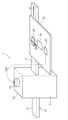
- FIG. 1 is a diagram showing a schematic configuration of a shutoff system 1 according to the first embodiment.
- the cutoff system 1 includes a busbar 10, a cutoff device 20, a board 30, a current sensor 40, a control circuit 50, and an ignition circuit 60.
- the bus bar 10 is a linear and flat conductor, and is arranged to penetrate a case 21 that forms the outer shell of the disconnection device 20.
- the upper surface (the upper surface in FIG. 1) and the lower surface (the lower surface in FIG. 1) of the bus bar 10 are the left side (the surface on the near side in the paper in FIG. 1) and the right side (the surface on the back side in the paper in FIG. 1). It has a wide surface with a larger dimension in the width direction compared to the .
- the upper surface (or lower surface) of the bus bar 10 is also referred to as the wide surface 11.
- a first end of both longitudinal ends of the bus bar 10 is connected to a positive electrode (or negative electrode) of a battery, and a second end is connected to one end (or other end) of a load. That is, the bus bar 10 is inserted into the power supply path PL that connects the positive electrode (or negative electrode) of the battery and one end (or the other end) of the load. Note that the bus bar 10 may be a part of the component of the disconnection device 20.
- the cutoff device 20 is a device that cuts off the supply of power in the power supply path PL.
- the shutoff device 20 is a pyrofuse (pyrotechnic shutoff device, irreversible pyrotechnic shutoff device).
- the cutoff device 20 cuts off a portion of the bus bar 10 based on the cutoff signal output from the ignition circuit 60, thereby cutting off the power supply path PL.
- the cutoff device 20 cuts off the power supply path PL by dividing a portion of the bus bar 10 located inside the cutoff device 20 with a piston housed inside the cutoff device 20.
- the shutoff device 20 includes a case 21 forming an outer shell, a piston movable in a direction perpendicular to the wide surface 11 of the bus bar 10 (vertical direction in FIG. 1), and an ignition part 22 that activates the piston. It is equipped with. Note that in FIG. 1, illustration of the piston is omitted.
- the case 21 has a cylindrical shape that is long in the direction orthogonal to the wide surface 11 of the bus bar 10.
- the bus bar 10 is disposed to penetrate the case 21. Further, inside the case 21, a part where the bus bar 10 is divided, a piston, and an ignition part 22 are arranged.
- the case 21 has a rectangular parallelepiped shape in FIG. 1, this does not necessarily represent the actual shape.
- the ignition unit 22 is mainly provided inside the case 21. A portion of the ignition section 22 is exposed to the outside of the case 21 as an input terminal that receives a cutoff signal from the ignition circuit 60.
- the ignition unit 22 operates the piston when receiving a cutoff signal from the ignition circuit 60, that is, when an abnormality occurs in the power supply path PL.
- the occurrence of an abnormality in the power supply path PL here means that an overcurrent flows in the power supply path PL, in other words, in the bus bar 10 due to, for example, a short circuit.
- the ignition unit 22 upon receiving the cutoff signal from the ignition circuit 60, the ignition unit 22 ignites explosives to rapidly expand the gas in the case 21, thereby causing the piston to move toward the bus bar 10 located in the case 21. Move at high speed towards one part. As a result, the piston collides with a part of the bus bar 10, part of the bus bar 10 is separated, and the power supply path PL is cut off.
- the substrate 30 is rectangular and flat, and is made of an electrically insulating material.
- the substrate 30 is arranged above the bus bar 10.
- a current sensor 40, a control circuit 50, and an ignition circuit 60 are mounted and arranged on the upper surface of the substrate 30. Since the current sensor 40 is arranged above the bus bar 10 with the electrically insulating substrate 30 in between, the current sensor 40 is arranged at a predetermined distance from the bus bar 10 and is electrically insulated from the bus bar 10. ing. That is, the current sensor 40 is arranged so as not to come into contact with the bus bar 10.
- the substrate 30 may be placed on the top surface of the bus bar 10, or may be placed so as not to come into contact with the bus bar 10, such as by being fixed to another member around the isolation system 1.
- the current sensor 40 is a sensor that measures the current Ib flowing through the bus bar 10, and is a non-contact current sensor that is placed with a space between it and the bus bar 10.
- the current sensor 40 is particularly a coreless magnetic sensor, and is further a current sensor using a TMR (Tunnel Magnetoresistive) element as a magnetoresistive element.
- TMR Tunnelnel Magnetoresistive
- the magnetic resistance of the magnetoresistive element (here, TMR element) changes depending on the magnitude of the magnetic flux passing through the current sensor 40.
- the current sensor 40 is configured by an IC (Integrated Circuit) that includes a magnetoresistive element and a signal processing circuit.
- the signal processing circuit amplifies the potential difference caused by passing a current through the magnetoresistive element, processes the amplified potential difference, and outputs a signal corresponding to the magnitude of the magnetic flux passing through the current sensor 40.
- the current flowing through the magnetoresistive element is a current flowing from a power source for driving the current sensor 40, and is not the current Ib flowing through the bus bar 10. Further, the current flowing through the magnetoresistive element is very small compared to the current flowing through the bus bar 10.
- the magnetic flux passing through the current sensor 40 changes depending on the magnitude of the current Ib flowing through the bus bar 10. Therefore, the current sensor 40 can measure the current Ib flowing through the bus bar 10 without contacting the bus bar 10 based on the magnitude of the magnetic resistance of the magnetoresistive element, in other words, the magnitude of the magnetic flux. .
- the current sensor 40 is a magnetic sensor that can detect the magnetic flux passing through the current sensor 40 in one axis. Specifically, the current sensor 40 can detect magnetic flux along one axis along the width direction of the wide surface 11 of the bus bar 10 .
- FIG. 2 is a schematic diagram of the current sensor 40 and bus bar 10 according to the first embodiment viewed from above.
- illustration of the cutoff device 20, the board 30, the control circuit 50, and the ignition circuit 60 is omitted.
- FIG. 3 is a schematic diagram of the current sensor 40 and bus bar 10 according to the first embodiment, viewed from the right in FIG. 1.
- illustration of the cutoff device 20, the board 30, the control circuit 50, and the ignition circuit 60 is omitted.
- this space is a place where the change in the magnetic flux ⁇ 0 generated by the current Ib flowing through the bus bar 10 is relatively small. Therefore, if the current sensor 40 is placed in this space, even if the current sensor 40 is misaligned during design, the magnetic flux ⁇ 0 passing through the current sensor 40 will hardly change, so the misalignment of the current sensor 40 will be avoided. This has the advantage that the measurement accuracy of the current sensor 40 is not easily affected.
- the control circuit 50 is a circuit that controls the drive of the interrupting device 20 based on the measured value of the current sensor 40.
- the control circuit 50 is composed of, for example, an IC. Further, the control circuit 50 is electrically connected to the current sensor 40 and is configured to obtain the measured value of the current sensor 40.
- the control circuit 50 compares the measured value of the current sensor 40, that is, the current value of the current Ib flowing through the bus bar 10, with a threshold value stored in advance in a memory or the like, and determines that the current value exceeds the threshold value. Then, an electric signal is output to the ignition circuit 60. This electric signal is amplified by the ignition circuit 60, and the amplified electric signal is input to the ignition section 22 of the disconnection device 20 as a disconnection signal. This causes the ignition section 22 of the shutoff device 20 to operate the piston.
- the control circuit 50 monitors whether an overcurrent is flowing through the bus bar 10, that is, whether an abnormality has occurred in the power supply path PL, by referring to the measured value of the current sensor 40. .
- the control circuit 50 outputs a cutoff signal to the ignition section 22 of the cutoff device 20 via the ignition circuit 60, thereby driving the cutoff device 20 to The power supply path PL is cut off by dividing a part of the power supply path PL.
- control circuit 50 when the control circuit 50 is communicably connected to, for example, an ECU (Electronic Control Unit) mounted on a vehicle, the control circuit 50 uses the reception of a signal output from the ECU notifying the occurrence of an abnormality as a trigger to generate electricity. A signal may be output to the ignition circuit 60.
- ECU Electronic Control Unit
- the ignition circuit 60 is a circuit that amplifies the electrical signal output from the control circuit 50 and outputs the amplified electrical signal (that is, a cutoff signal) to the ignition section 22 of the cutoff device 20.
- the ignition circuit 60 is configured by, for example, an IC.
- the ignition circuit 60 amplifies the electric signal output from the control circuit 50 to a level that can ignite the gunpowder included in the ignition section 22 .
- the current sensor 40 is a non-contact type current sensor arranged with a space between the current sensor 40 and the bus bar 10 . Therefore, the current Ib flowing through the bus bar 10 does not flow through the current sensor 40, so even in applications where a large current flows in the power supply path PL, no large current flows through the current sensor 40, and the current sensor 40 Excessive heat is not generated. Therefore, the shutoff system 1 according to the first embodiment has the advantage that generation of heat caused by the current Ib flowing through the bus bar 10 can be suppressed. Therefore, in the cutoff system 1 according to the first embodiment, a structure for cooling the heat generated by the current sensor 40 is not required, so that the manufacturing cost of the cutoff system 1 can be reduced.
- the current sensor 40 is a coreless type current sensor. Therefore, since the current sensor 40 does not require a magnetic core, there is no measurement error due to magnetic hysteresis, and the measurement accuracy of the current Ib flowing through the bus bar 10 is higher than that of a current sensor using a magnetic core. There are advantages.
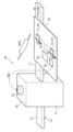
- FIG. 4 is a diagram showing a schematic configuration of a shutoff system 1A according to the second embodiment.
- the interruption system 1A according to the second embodiment differs from the interruption system 1 according to the first embodiment mainly in that it includes a plurality of current sensors 40.
- descriptions of common points with the shutoff system 1 according to Embodiment 1 will be omitted.
- the shutoff system 1A includes a plurality of (here, two) current sensors 40.
- one current sensor 40 of the two current sensors 40 is also referred to as a first current sensor 41, and the other current sensor 40 is also referred to as a second current sensor 42.
- Each of the first current sensor 41 and the second current sensor 42 is a magnetic sensor that can detect magnetic flux in two axes.
- the first current sensor 41 and the second current sensor 42 both have an axis along the width direction of the wide surface 11 of the bus bar 10 and an axis along the direction perpendicular to the wide surface 11 of the bus bar 10. , magnetic flux can be detected in two axes.
- the first current sensor 41 and the second current sensor 42 are both arranged to face the upper surface of the bus bar 10.
- the plurality of current sensors 40 are all arranged on the same side facing the wide surface 11 (here, above the wide surface 11).
- the first current sensor 41 and the second current sensor 42 are located inside the wide surface 11 of the bus bar 10 when viewed from above (that is, viewed from a direction perpendicular to the wide surface 11 of the bus bar 10). It is arranged to fit in.
- first current sensor 41 and the second current sensor 42 are arranged so as to be lined up along the longitudinal direction of the bus bar 10. Therefore, the magnetic flux that is generated when the current Ib flows through the bus bar 10 and passes through the first current sensor 41 and the magnetic flux that is generated when the current Ib flows through the bus bar 10 and passes through the second current sensor 42 are almost the same. They are the same size and have the same orientation. In the following, these magnetic fluxes will be referred to as "magnetic flux ⁇ 1".
- the first current sensor 41 and the second current sensor 42 are the same type of sensor. However, the first current sensor 41 and the second current sensor 42 are arranged such that they are rotated 180 degrees from each other in a plane parallel to the wide surface 11 of the bus bar 10 . Therefore, the first current sensor 41 and the second current sensor 42 have different polarities of current measurement values.
- the first current sensor 41 outputs a measured value of positive polarity
- the second current sensor 42 outputs a measured value of negative polarity.
- the control circuit 50 is electrically connected to each of the first current sensor 41 and the second current sensor 42, and is configured to obtain the measured value of the first current sensor 41 and the measured value of the second current sensor 42. It is composed of Then, the control circuit 50 calculates the current value of the current Ib flowing through the bus bar 10 based on the measured value of the first current sensor 41 and the measured value of the second current sensor 42, and sets the calculated current value and the threshold value. By comparing the values, it is monitored whether or not an overcurrent is flowing through the bus bar 10.
- control circuit 50 in the second embodiment executes the process of calculating the current value of the current Ib flowing through the bus bar 10 using the measured values of each of the plurality of current sensors 40. This is different from the circuit 50. Specifically, the control circuit 50 calculates the difference between the measured value of the first current sensor 41 and the measured value of the second current sensor 42, and divides the calculated difference by 2, so that the current flows to the bus bar 10. Calculate the current value of current Ib.
- the second embodiment at least a part of the external noise is removed (that is, noise canceling) by referring to the measured value of the first current sensor 41 and the measured value of the second current sensor 42 as described above. This suppresses a decrease in measurement accuracy of the current Ib flowing through the bus bar 10.
- f( ⁇ 1) represents the current value corresponding to the magnetic flux ⁇ 1 passing through the first current sensor 41
- f(- ⁇ 1) represents the current value corresponding to the magnetic flux ⁇ 1 passing through the first current sensor 42. represents the current value corresponding to the magnetic flux ⁇ 1 passing through.
- f( ⁇ N1) represents a current value corresponding to the magnetic flux ⁇ N1 passing through each of the first current sensor 41 and the second current sensor 42.
- the magnetic flux ⁇ N1 is a magnetic flux included in external noise along a direction orthogonal to the wide surface 11 of the bus bar 10.
- the wide surface of the bus bar 10 of the external noise is Magnetic flux along the direction perpendicular to 11 can be canceled. That is, in the cutoff system 1A according to the second embodiment, at least a portion of the external noise is removed by referring to the measured values of the first current sensor 41 and the second current sensor 42 that can be detected in two axes. This has the advantage that it is possible to suppress a decrease in measurement accuracy of the current Ib flowing through the bus bar 10.
- the control circuit 50 may further have a function of detecting a failure of the current sensor 40. Specifically, the control circuit 50 calculates the difference between the measured value of the first current sensor 41 and the measured value of the second current sensor 42, and sets the calculated difference to a predetermined threshold value stored in advance in a memory or the like. Monitor whether it is within the range. Then, the control circuit 50 detects that one of the first current sensor 41 and the second current sensor 42 has failed when the calculated difference deviates from a predetermined threshold range. In this case, for example, the control circuit 50 notifies the user of the abnormality, and the first current sensor 41 and the second current sensor 42 are replaced with new ones, so that the current Ib flowing through the bus bar 10 cannot be accurately measured. Improvements can be made.
- the shutoff system 1A may include three current sensors 40.
- the control circuit 50 has a function of detecting failure of the current sensor 40, it is possible to specify which current sensor 40 is malfunctioning. For example, the control circuit 50 selects two current sensors 40 out of the three current sensors 40, calculates the difference between the measured values of each of the two selected current sensors 40, and sets the calculated difference within a predetermined threshold range. Monitor whether it is within the range. Since there are six combinations of selecting two current sensors 40 from three current sensors 40, the control circuit 50 monitors whether the calculated difference falls within a predetermined threshold range for each of the six combinations. .
- the control circuit 50 can identify the faulty current sensor 40. In this case, by replacing only the faulty current sensor 40 with a new one, it is possible to improve the situation in which the current Ib flowing through the bus bar 10 cannot be accurately measured.
- FIG. 5 is a diagram showing a schematic configuration of a shutoff system 1B according to the third embodiment.
- the interruption system 1B according to the third embodiment differs from the interruption system 1A according to the second embodiment mainly in the arrangement of the plurality of current sensors 40.
- description of the points common to the shutoff system 1A according to the second embodiment will be omitted.
- the first current sensor 41 and the second current sensor 42 are both magnetic sensors that can detect magnetic flux in one axis, similar to the current sensor 40 in the first embodiment. Specifically, both the first current sensor 41 and the second current sensor 42 can detect magnetic flux along an axis along the width direction of the wide surface 11 of the bus bar 10 .
- the first current sensor 41 and the second current sensor 42 are both arranged to face the upper surface of the bus bar 10.
- the plurality of current sensors 40 are all arranged on the same side facing the wide surface 11 (here, above the wide surface 11).
- the first current sensor 41 is arranged so as to fit inside the wide surface 11 of the bus bar 10 when viewed from above (that is, when viewed from a direction perpendicular to the wide surface 11 of the bus bar 10).
- the second current sensor 42 is arranged at a predetermined distance from the bus bar 10. Specifically, the second current sensor 42 is arranged along the width direction of the wide surface 11 of the bus bar 10 together with the first current sensor 41, and is arranged so that the magnetic flux ⁇ 3 is much smaller than the magnetic flux ⁇ 2. It is located in
- the magnetic flux ⁇ 2 is a magnetic flux generated by the current Ib flowing through the bus bar 10 and passing through the first current sensor 41.
- the magnetic flux ⁇ 3 is a magnetic flux generated by the current Ib flowing through the bus bar 10 and passes through the second current sensor 42, and has the same direction as the magnetic flux ⁇ 2.
- the magnetic flux ⁇ 3 is about one tenth of the magnetic flux ⁇ 2.
- magnetic flux ⁇ N2 the magnetic flux that passes through the first current sensor 41 among the external noises and the magnetic flux that passes through the second current sensor 42 among the external noises have almost the same magnitude and are in the same direction.
- magnetic flux ⁇ N2 the magnetic flux of these external noises.
- the first current sensor 41 and the second current sensor 42 are the same type of sensors, and the polarity of the current measurement value is also the same. That is, in the third embodiment, the first current sensor 41 and the second current sensor 42 are arranged without being rotated by 180 degrees in a plane parallel to the wide surface 11 of the bus bar 10.
- the control circuit 50 calculates the current value of the current Ib flowing through the bus bar 10 by calculating the difference between the measured value of the first current sensor 41 and the measured value of the second current sensor 42. . That is, in Embodiment 3, as in Embodiment 2, at least part of external noise is removed (that is, noise By canceling the current Ib flowing through the bus bar 10, a decrease in measurement accuracy of the current Ib flowing through the bus bar 10 is suppressed.
- Equation (4) “f( ⁇ 2)” represents the current value corresponding to the magnetic flux ⁇ 2 passing through the first current sensor 41. Furthermore, in Equation (5), “f( ⁇ 3)” represents the current value corresponding to the magnetic flux ⁇ 3 passing through the second current sensor 42. Furthermore, in equations (4) and (5), “f( ⁇ N2)” represents a current value corresponding to the magnetic flux ⁇ N2 passing through each of the first current sensor 41 and the second current sensor 42.
- the magnetic flux ⁇ N2 is a magnetic flux included in the external noise along the width direction of the wide surface 11 of the bus bar 10.
- Equation (6) Since the magnetic flux ⁇ 3 is much smaller than the magnetic flux ⁇ 2, “f( ⁇ 2)>>f( ⁇ 3)” and “f( ⁇ 3)” is ignored.
- the magnetic flux along the width direction of the wide surface 11 of the bus bar 10, which is included in the external noise is reduced. Can be canceled. That is, in the interrupting system 1B according to the third embodiment, at least a part of the external noise is removed by referring to the measured values of the first current sensor 41 and the second current sensor 42 that can be detected in one axis. This has the advantage that it is possible to suppress a decrease in measurement accuracy of the current Ib flowing through the bus bar 10.
- control circuit 50 may further have a function of detecting a failure of the current sensor 40, similarly to the cutoff system 1A according to the second embodiment. Further, the cutoff system 1B according to the third embodiment may include three current sensors 40 similarly to the cutoff system 1A according to the second embodiment.
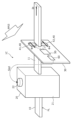
- FIG. 6 is a diagram showing a schematic configuration of a shutoff system 1C according to the fourth embodiment.
- the interruption system 1C according to the fourth embodiment differs from the interruption system 1A according to the second embodiment mainly in the arrangement of the plurality of current sensors 40.
- description of the points common to the shutoff system 1A according to the second embodiment will be omitted.
- the first current sensor 41 and the second current sensor 42 are both magnetic sensors that can detect magnetic flux in one axis, similar to the current sensor 40 in the first embodiment. Specifically, both the first current sensor 41 and the second current sensor 42 can detect magnetic flux along an axis along the width direction of the wide surface 11 of the bus bar 10 .
- the substrate 30 is arranged such that its mounting surface is parallel to a direction perpendicular to the wide surface 11 of the bus bar 10 and that the bus bar 10 passes through it.
- the first current sensor 41 and the second current sensor 42 are arranged to sandwich the bus bar 10 in a direction perpendicular to the wide surface 11 of the bus bar 10.
- the first current sensor 41 is arranged above the bus bar 10 and the second current sensor 42 is arranged below the bus bar 10.
- the first current sensor 41 and the second current sensor 42 are arranged in a direction perpendicular to the wide surface 11 of the bus bar 10 .
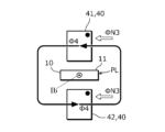
- the magnetic flux generated by flowing through the bus bar 10 and passing through the first current sensor 41 and the magnetic flux generated by flowing through the bus bar 10 and passing through the second current sensor 42 are as follows. They are almost the same size, but their orientations are different. In the following, these magnetic fluxes will be referred to as "magnetic flux ⁇ 4".
- FIG. 7 is a schematic diagram of the first current sensor 41, the second current sensor 42, and the bus bar 10 according to the fourth embodiment, viewed from the right.
- illustration of the cutoff device 20, the board 30, the control circuit 50, and the ignition circuit 60 is omitted.
- the magnetic flux of these external noises will be referred to as "magnetic flux ⁇ N3.”
- the first current sensor 41 and the second current sensor 42 are the same type of sensors, and the polarity of the current measurement value is also the same. That is, in the fourth embodiment, the first current sensor 41 and the second current sensor 42 are arranged without being rotated by 180 degrees with respect to each other in a plane orthogonal to the wide surface 11 of the bus bar 10.
- the control circuit 50 calculates the difference between the measured value of the first current sensor 41 and the measured value of the second current sensor 42, and divides the calculated difference by 2, thereby controlling the bus bar 10.
- the current value of the flowing current Ib is calculated. That is, in the fourth embodiment, as in the second and third embodiments, at least part of the external noise is removed (i.e., , noise canceling), thereby suppressing a decrease in measurement accuracy of the current Ib flowing through the bus bar 10.
- the wide surface of the bus bar 10 of the external noise is The magnetic flux along the width direction of 11 can be canceled. That is, in the cutoff system 1C according to the fourth embodiment, at least a part of the external noise is removed by referring to the measured values of the first current sensor 41 and the second current sensor 42 that can be detected in one axis. This has the advantage that it is possible to suppress a decrease in measurement accuracy of the current Ib flowing through the bus bar 10.
- control circuit 50 may further have a function of detecting a failure of the current sensor 40, similarly to the shutoff system 1A according to the second embodiment.
- the cutoff system 1C according to the fourth embodiment may include three current sensors 40 similarly to the cutoff system 1A according to the second embodiment.
- FIG. 8 is a diagram showing a schematic configuration of a shutoff system 1D according to the fifth embodiment.
- solid arrows represent magnetic flux generated by the current Ib flowing through the bus bar 10
- wide dashed arrows represent magnetic flux as external noise. Note that in FIG. 8, illustration of the shutoff device 20 is omitted.
- the shutoff system 1D according to the fifth embodiment differs from the shutoff system 1C according to the fourth embodiment mainly in that it includes two substrates 30 and 31.
- description of the points common to the shutoff system 1C according to the fourth embodiment will be omitted.
- One of the two substrates 30 and 31 is placed above the bus bar 10, and the other substrate 31 is placed below the bus bar 10, as in the first embodiment.
- the substrates 30 and 31 are both arranged so that their mounting surfaces are parallel to the wide surface 11 of the bus bar 10.
- the first current sensor 41 is arranged on one substrate 30, and the second current sensor 42 is arranged on the other substrate 31.
- One substrate 30 and the other substrate 31 are mechanically and electrically connected by a connector 70.
- the first current sensor 41 and the second current sensor 42 are both arranged so that the thickness direction coincides with the direction perpendicular to the wide surface 11.
- the first current sensor 41 and the second current sensor 42 are arranged such that the mounting surfaces of the respective substrates 30 and 31 are parallel to the wide surface 11 of the bus bar 10. Therefore, in the fifth embodiment, the magnetic flux passing through each of the first current sensor 41 and the second current sensor 42 is larger than that in the fourth embodiment, so that the measurement accuracy of the current Ib flowing through the bus bar 10 is reduced.
- the advantage is that it can be improved.
- the shutoff systems 1, 1A, 1B, 1C, and 1D of the present disclosure include the bus bar 10, the shutoff device 20, the current sensor 40, and the control circuit 50.
- Bus bar 10 is inserted into power supply path PL.
- the cutoff device 20 cuts off the power supply path PL when a part of the bus bar 10 is cut off.
- Current sensor 40 measures the current flowing through bus bar 10 .
- the control circuit 50 controls the driving of the interrupting device 20 based on the measured value of the current sensor 40.
- the current sensor 40 is a non-contact type current sensor, and is arranged at a distance from the bus bar 10.
- the current Ib flowing through the bus bar 10 does not flow through the current sensor 40, so even in applications where a large current flows through the power supply path PL, no large current flows through the current sensor 40, and the current Excessive heat is not generated in the sensor 40. Therefore, there is an advantage that generation of heat caused by the current Ib flowing through the bus bar 10 can be suppressed.
- the current sensor 40 is arranged so as to face the wide surface 11 of the bus bar 10.
- the current sensor 40 is arranged so as to fit inside the wide surface 11 when viewed from a direction perpendicular to the wide surface 11. That is, it is preferable that the current sensor 40 is arranged such that the entire current sensor overlaps the wide surface 11 when viewed from a direction orthogonal to the wide surface 11.
- first current sensor 41 and the second current sensor 42 are located on the same side with respect to the wide surface 11 of the bus bar 10, and face the wide surface 11, and each of the first current sensor 41 and the second current sensor 42 can detect magnetic flux along two axes: an axis along the width direction of the wide surface 11 and an axis along a direction perpendicular to the wide surface 11, and the first current sensor 41 and the second current sensor 42 , it is preferable that the polarities of the measured current values are different from each other.
- first current sensor 41 and the second current sensor 42 are arranged on the same surface parallel to the wide surface 11, and on the same surface, the first current sensor 41 is 180 degrees above the second current sensor. It is preferable that they be rotated by a degree.
- first current sensor 41 and the second current sensor 42 are located on the same side with respect to the wide surface 11 of the bus bar 10, and the first current sensor 41 is arranged to face the wide surface 11 of the bus bar 10. Therefore, it is preferable that the second current sensor 42 is disposed further away from the bus bar 10 than the first current sensor 41 is.
- first current sensor 41 and the second current sensor 42 are arranged on the same plane perpendicular to the direction in which the bus bar 10 extends, and the bus bar 10 extends between the first current sensor 41 and the second current sensor 42. Then it is preferable.
- first current sensor 41 and the second current sensor 42 are both arranged so that the thickness direction thereof coincides with the direction orthogonal to the wide surface 11.
- the current sensor 40 may be a coreless magnetic sensor.
- the current sensor 40 does not require a magnetic core, so there is no measurement error due to magnetic hysteresis, and the measurement accuracy of the current Ib flowing through the bus bar 10 is improved compared to a current sensor using a magnetic core. It has the advantage of being expensive.
- the current sensor 40 may be a magnetic sensor using a tunnel magnetoresistive element.
- the sensitivity to magnetism is higher than when the current sensor 40 is a magnetic sensor using, for example, a GMR (Giant Magnetoresistance) element, so the measurement accuracy of the current Ib flowing through the bus bar 10 is improved.
- GMR Gate Magnetoresistance
- the current sensor 40 does not need to be arranged to face the wide surface 11 of the bus bar 10. That is, the current sensor 40 may be arranged to face the side surface of the bus bar 10. Even in this case, it is possible to measure the current Ib flowing through the bus bar 10 as long as the current sensor 40 is arranged so that the magnetic flux ⁇ 0 generated by the current Ib flowing through the bus bar 10 passes through.
- the first current sensor 41 and the second current sensor 42 may be realized by different types of current sensors whose current measurement values have different polarities.
- control circuit 50 and the ignition circuit 60 may be configured integrally.
- control circuit 50 may have a function as the ignition circuit 60.
- the current sensor 40 is a current sensor using an AMR (Anisotropic Magnetoresistance) element or a GMR (Giant Magnetoresistance) element as a magnetoresistive element. It's okay.
- the shutoff system is installed, for example, in a vehicle such as a car, or an electrical product such as a home appliance.
- Vehicles include, for example, vehicles equipped with batteries such as BEVs (Battery Electric Vehicles) and PHEVs (Plug-in Hybrid Vehicles).
- BEVs Battery Electric Vehicles
- PHEVs Plug-in Hybrid Vehicles
- the cutoff system may be mounted on an object having an electric circuit other than a vehicle or an electric product.
- the cutoff system in each of the above embodiments may be used, for example, to cut off overcurrent in a power storage system, a power transmission system, or the like.
- the present disclosure is useful for a shutoff system that shuts off a power supply path when an overcurrent occurs.
- Cutoff system 10 Bus bar 11 Wide surface 20 Cutoff device 21 Case 22 Ignition part 30, 31 Board 40 Current sensor 41 First current sensor 42 Second current sensor 50 Control circuit 60 Ignition circuit 70 Connector ⁇ 1 , ⁇ 2, ⁇ 3, ⁇ 4, ⁇ N1, ⁇ N2, ⁇ N3 Magnetic flux Ib Current PL Power supply path
Landscapes
- Physics & Mathematics (AREA)
- General Physics & Mathematics (AREA)
- Engineering & Computer Science (AREA)
- Power Engineering (AREA)
- Measuring Instrument Details And Bridges, And Automatic Balancing Devices (AREA)
Priority Applications (1)
| Application Number | Priority Date | Filing Date | Title |
|---|---|---|---|
| JP2024526316A JPWO2023238585A1 (https=) | 2022-06-06 | 2023-05-10 |
Applications Claiming Priority (2)
| Application Number | Priority Date | Filing Date | Title |
|---|---|---|---|
| JP2022091254 | 2022-06-06 | ||
| JP2022-091254 | 2022-06-06 |
Publications (1)
| Publication Number | Publication Date |
|---|---|
| WO2023238585A1 true WO2023238585A1 (ja) | 2023-12-14 |
Family
ID=89118253
Family Applications (1)
| Application Number | Title | Priority Date | Filing Date |
|---|---|---|---|
| PCT/JP2023/017539 Ceased WO2023238585A1 (ja) | 2022-06-06 | 2023-05-10 | 遮断システム |
Country Status (2)
| Country | Link |
|---|---|
| JP (1) | JPWO2023238585A1 (https=) |
| WO (1) | WO2023238585A1 (https=) |
Cited By (1)
| Publication number | Priority date | Publication date | Assignee | Title |
|---|---|---|---|---|
| WO2026059893A1 (en) * | 2024-09-10 | 2026-03-19 | Sensata Technologies Inc. | Overcurrent protection in electric vehicle systems using differential hall sensors |
Citations (6)
| Publication number | Priority date | Publication date | Assignee | Title |
|---|---|---|---|---|
| JP2004037147A (ja) * | 2002-07-01 | 2004-02-05 | Tdk Corp | 過電流センサ |
| JP2005195427A (ja) * | 2004-01-06 | 2005-07-21 | Asahi Kasei Electronics Co Ltd | 電流測定装置、電流測定方法および電流測定プログラム |
| JP2011112510A (ja) * | 2009-11-26 | 2011-06-09 | Honda Motor Co Ltd | 電流検出装置 |
| JP2012002561A (ja) * | 2010-06-15 | 2012-01-05 | Denso Corp | 電流センサ |
| WO2012117841A1 (ja) * | 2011-03-02 | 2012-09-07 | アルプス・グリーンデバイス株式会社 | 電流センサ |
| JP2016133498A (ja) * | 2015-01-22 | 2016-07-25 | 日本特殊陶業株式会社 | 電流電力センサ |
-
2023
- 2023-05-10 JP JP2024526316A patent/JPWO2023238585A1/ja active Pending
- 2023-05-10 WO PCT/JP2023/017539 patent/WO2023238585A1/ja not_active Ceased
Patent Citations (6)
| Publication number | Priority date | Publication date | Assignee | Title |
|---|---|---|---|---|
| JP2004037147A (ja) * | 2002-07-01 | 2004-02-05 | Tdk Corp | 過電流センサ |
| JP2005195427A (ja) * | 2004-01-06 | 2005-07-21 | Asahi Kasei Electronics Co Ltd | 電流測定装置、電流測定方法および電流測定プログラム |
| JP2011112510A (ja) * | 2009-11-26 | 2011-06-09 | Honda Motor Co Ltd | 電流検出装置 |
| JP2012002561A (ja) * | 2010-06-15 | 2012-01-05 | Denso Corp | 電流センサ |
| WO2012117841A1 (ja) * | 2011-03-02 | 2012-09-07 | アルプス・グリーンデバイス株式会社 | 電流センサ |
| JP2016133498A (ja) * | 2015-01-22 | 2016-07-25 | 日本特殊陶業株式会社 | 電流電力センサ |
Cited By (1)
| Publication number | Priority date | Publication date | Assignee | Title |
|---|---|---|---|---|
| WO2026059893A1 (en) * | 2024-09-10 | 2026-03-19 | Sensata Technologies Inc. | Overcurrent protection in electric vehicle systems using differential hall sensors |
Also Published As
| Publication number | Publication date |
|---|---|
| JPWO2023238585A1 (https=) | 2023-12-14 |
Similar Documents
| Publication | Publication Date | Title |
|---|---|---|
| JP7111387B2 (ja) | 複合型電流測定装置 | |
| EP2942631B1 (en) | Hybrid current sensor assembly | |
| JP5577544B2 (ja) | 電流センサ | |
| US10861663B2 (en) | Relay device and a method to detect open-circuit failures | |
| US10018657B2 (en) | Current measuring circuit, battery and motor vehicle | |
| US10222423B2 (en) | Electrical storage system | |
| JP6046864B1 (ja) | 2つの異なるバッテリセルの2つのセル電流の差分を測定する装置を備えた、複数の電気化学的なバッテリセルを有するバッテリパック | |
| US20180321281A1 (en) | Current sensor | |
| KR102194985B1 (ko) | 배터리 보호 회로 및 이를 포함하는 배터리 팩 | |
| KR20210093767A (ko) | 저항 어셈블리, 저항 어셈블리를 구비한 측정 회로, 그리고 저항 어셈블리용 스트립형 복합 재료의 제조 방법 | |
| US10379150B2 (en) | Earth fault detector | |
| WO2012043591A1 (ja) | 電源装置 | |
| US20110187346A1 (en) | Current detecting device | |
| CN110011281A (zh) | 电池过充电防止装置 | |
| JP7765756B2 (ja) | 電流計測装置、蓄電装置 | |
| JP2016006407A (ja) | 出力電流及び地絡抵抗の検出装置 | |
| JP2010175276A (ja) | 磁気比例式電流センサ | |
| US20210383985A1 (en) | Relay module | |
| JP2021021580A (ja) | 電流計測装置、電流の計測方法、蓄電装置及び抵抗器 | |
| WO2023238585A1 (ja) | 遮断システム | |
| US10850618B2 (en) | Connection module for an electrical energy storage device, and power supply system | |
| CN117471159A (zh) | 电流传感器 | |
| KR20130088284A (ko) | 파워 릴레이 어셈블리 | |
| JP7549027B2 (ja) | 電流センサ | |
| JP6477296B2 (ja) | 電流検出装置 |
Legal Events
| Date | Code | Title | Description |
|---|---|---|---|
| 121 | Ep: the epo has been informed by wipo that ep was designated in this application |
Ref document number: 23819569 Country of ref document: EP Kind code of ref document: A1 |
|
| ENP | Entry into the national phase |
Ref document number: 2024526316 Country of ref document: JP Kind code of ref document: A |
|
| NENP | Non-entry into the national phase |
Ref country code: DE |
|
| 122 | Ep: pct application non-entry in european phase |
Ref document number: 23819569 Country of ref document: EP Kind code of ref document: A1 |