WO2023238578A1 - ユニット - Google Patents
ユニット Download PDFInfo
- Publication number
- WO2023238578A1 WO2023238578A1 PCT/JP2023/017458 JP2023017458W WO2023238578A1 WO 2023238578 A1 WO2023238578 A1 WO 2023238578A1 JP 2023017458 W JP2023017458 W JP 2023017458W WO 2023238578 A1 WO2023238578 A1 WO 2023238578A1
- Authority
- WO
- WIPO (PCT)
- Prior art keywords
- capacitor
- electric circuit
- radial direction
- viewed
- case
- Prior art date
- Legal status (The legal status is an assumption and is not a legal conclusion. Google has not performed a legal analysis and makes no representation as to the accuracy of the status listed.)
- Ceased
Links
Images



Classifications
-
- H—ELECTRICITY
- H02—GENERATION; CONVERSION OR DISTRIBUTION OF ELECTRIC POWER
- H02K—DYNAMO-ELECTRIC MACHINES
- H02K11/00—Structural association of dynamo-electric machines with electric components or with devices for shielding, monitoring or protection
- H02K11/0094—Structural association with other electrical or electronic devices
-
- H—ELECTRICITY
- H02—GENERATION; CONVERSION OR DISTRIBUTION OF ELECTRIC POWER
- H02K—DYNAMO-ELECTRIC MACHINES
- H02K11/00—Structural association of dynamo-electric machines with electric components or with devices for shielding, monitoring or protection
- H02K11/30—Structural association with control circuits or drive circuits
- H02K11/33—Drive circuits, e.g. power electronics
-
- H—ELECTRICITY
- H02—GENERATION; CONVERSION OR DISTRIBUTION OF ELECTRIC POWER
- H02K—DYNAMO-ELECTRIC MACHINES
- H02K7/00—Arrangements for handling mechanical energy structurally associated with dynamo-electric machines, e.g. structural association with mechanical driving motors or auxiliary dynamo-electric machines
- H02K7/003—Couplings; Details of shafts
-
- H—ELECTRICITY
- H02—GENERATION; CONVERSION OR DISTRIBUTION OF ELECTRIC POWER
- H02K—DYNAMO-ELECTRIC MACHINES
- H02K7/00—Arrangements for handling mechanical energy structurally associated with dynamo-electric machines, e.g. structural association with mechanical driving motors or auxiliary dynamo-electric machines
- H02K7/10—Structural association with clutches, brakes, gears, pulleys or mechanical starters
- H02K7/116—Structural association with clutches, brakes, gears, pulleys or mechanical starters with gears
-
- H—ELECTRICITY
- H02—GENERATION; CONVERSION OR DISTRIBUTION OF ELECTRIC POWER
- H02K—DYNAMO-ELECTRIC MACHINES
- H02K2211/00—Specific aspects not provided for in the other groups of this subclass relating to measuring or protective devices or electric components
- H02K2211/03—Machines characterised by circuit boards, e.g. pcb
Definitions
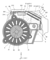
- FIG. 1 is a perspective view showing the unit 1 (with the fourth case 24 removed) according to the present embodiment.
- FIG. 2 is a cross-sectional view showing the unit 1 according to this embodiment.
- FIG. 3 is a perspective view showing the fourth case 24.
- the unit 1 shown in FIGS. 1 to 3 is used to drive drive wheels (not shown) of a vehicle, but is not limited to this, and may be used to drive an electrical product, for example.
- the unit 1 is also called a motor unit (a unit having at least a motor), a power transmission device (a device having at least a power transmission mechanism (for example, a gear mechanism and/or a differential gear mechanism), etc.).
- a device (unit) having a motor and a power transmission mechanism belongs to the concepts of both a motor unit and a power transmission device.
- the unit 1 includes a housing 2, a motor 3 as a rotating electric machine, a drive shaft 4 as a shaft, a reduction gear group 5 as a gear mechanism, and an inverter 6.
- the first case 21 includes a tube 211 that is open at least at a front end, a front flange 212 that is provided at the front end of the tube 211 so as to protrude toward the outer circumference, and a front flange 212 that is the other end of the tube 211.
- a back flange 213 provided to protrude toward the outer circumference at the rear end; a protrusion 214 extending along the axial direction X and protruding toward the outer circumference in the cylinder 211 as the outer circumference of the motor 3; has.
- the axial direction X means the axial direction X of the rotating shaft of the parts that constitute the unit 1.
- the parts include, for example, a motor 3, a gear mechanism, a differential gear mechanism, and the like.
- the second case 22 is connected to the front end of the tube 211 of the first case 21. Specifically, the outer periphery of the second case 22 is connected to the front flange 212 by bolting. Further, the second case 22 supports both a front end as one end of a rotating shaft 31 of the motor 3 (described later) and a front end as one end of the drive shaft 4 via bearings (not shown).
- the motor 3 is a rotating electrical machine that has an electric motor function and/or a generator function.
- the motor 3 also has a rotating shaft 31 that is rotatably supported by the first case 21 and the second case 22 via bearings (not shown), and a rotating shaft 31 that is located on the outer circumferential side of the rotating shaft 31 and rotates integrally with the rotating shaft 31. and a stator 33 fixed to the inner circumferential side of the cylinder 211 so as to be located on the outer circumferential side of the rotor 32.
- the drive shaft 4 does not overlap the motor 3 (specifically, the rotating shaft 31, the rotor 32, and the stator 33) when viewed in the first radial direction. That is, the drive shaft 4 is offset from the motor 3 when viewed in the first radial direction. That is, the drive shaft 4 and the motor 3 are not lined up in the vertical direction Z.
- the third case 23 houses the reduction gear group 5.
- the third case 23 is constituted by a bottomed tube that is open at one front end and closed at the other rear end. Further, the third case 23 is connected to the rear end of the tube 211. Specifically, the outer periphery of the front end of the third case 23 is connected to the back flange 213 by bolting.
- the reduction gear group 5 has a portion that is offset from the motor 3 when viewed in the axial direction. That is, the reduction gear group 5 has a portion that does not overlap the motor 3 when viewed in the axial direction. That is, the reduction gear group 5 has a portion that is not lined up with the motor 3 in the axial direction X.
- the reduction gear group 5 is a power transmission mechanism that reduces the power of the motor 3 and transmits it to the drive shaft 4, and is composed of a plurality of gears.
- the reduction gear group 5 is dynamically connected to the downstream side of the motor 3 and the upstream side of the drive shaft 4 .
- the fourth case 24 constitutes the other part of the inverter case.
- the inverter 6 is attached to the fourth case 24.
- the fourth case 24 is connected to a portion of the outer periphery of the cylinder 211 (specifically, the arcuate portion 211a and the flat portion 211b) by tightening bolts.
- a part of the inverter 6 is housed in the accommodation area S formed by connecting the first case 21 and the fourth case 24.
- the fourth case 24 includes a first mounting part 241 to which one of a capacitor 61 and an electric circuit 62 (described later) of the inverter 6 is attached, and a second attachment part 242 to which the other of the capacitor 61 and an electric circuit 62 (described later) of the inverter 6 is attached. has.
- the first mounting part 241 is a plate extending in the horizontal direction Y
- the second mounting part 242 is a plate extending from the front side. This is a plate material that is inclined with respect to the lateral direction Y when viewed.
- the first attachment part 241 and the second attachment part 242 are opposite to the arcuate part 211a and the flat part 211b, respectively.
- the fourth case 24 has a portion that overlaps with the third case 23 that constitutes the gear mechanism (specifically, A first attachment part 241 and a second attachment part 242). That is, the fourth case 24 and the third case 23 are lined up in the axial direction X. This makes it possible to prevent the first attachment part 241 and the second attachment part 242 of the fourth case 24 from protruding from the third case 23 when viewed from the front, thereby reducing the size of the entire unit 1 in the radial direction. I can do it.
- the inverter 6 is a controller for controlling the drive of the motor 3.
- the inverter 6 includes a capacitor 61, an electric circuit 62, a cooler 63, a power connector 64, and connection wiring 65.
- the capacitor 61 (specifically, a smoothing capacitor) is an electronic component that stores and releases electricity.
- the capacitor 61 is attached to the back surface of the first attachment portion 241 so as to extend along the lateral direction Y when viewed from the front.
- the electric circuit 62 is electrically connected to the capacitor 61 and also to the motor 3 via the connection wiring 65.
- the electric circuit 62 is attached to the back surface of the second attachment part 242.
- the electric circuit 62 includes a PWR board 621 as a board arranged so as to be inclined with respect to the lateral direction Y (that is, the capacitor 61) when viewed from the front.
- the second mounting portion 242 to which the PWR board 621 is attached can also be arranged at an angle with respect to the lateral direction Y, so that the capacitor 61 and the PWR board 621 of the electric circuit 62 can be arranged side by side in the lateral direction Y.
- the unit 1 can be made smaller in the lateral direction Y compared to a configuration in which the unit 1 is arranged in the lateral direction Y.
- the unit 1 tends to have sloped or stepped portions, so the layout of the unit 1 as a whole can be improved.
- the cooler 63 is a member for cooling the PWR board 621.
- the cooler 63 is attached to the surface of the second attachment part 242. This makes it easier to arrange the cooling channel of the cooler 63 compared to a configuration in which the cooler 63 is attached to the back surface of the second attachment part 242. Note that, from the viewpoint of integrating the cooling channels, it is preferable that the unit oil cooler is also arranged on the surface of the second mounting portion 242.
- the capacitor 61 overlaps the motor 3 in the first radial direction, and the electric circuit 62 is aligned with the motor 3 in the vertical direction Z in the first radial direction. It overlaps with drive shaft 4, which is not installed. That is, the capacitor 61 and the motor 3 are lined up in the vertical direction Z, the electric circuit 62 is lined up in the vertical direction Z, and the drive shaft 4 that is not lined up with the motor 3 is lined up in the vertical direction Z.
- the drive shaft 4 is not located between the motor 3 and the inverter 6 when viewed in the first radial direction (that is, the drive shaft 4 is not located between the motor 3 and the inverter 6 when viewed from the first radial direction).
- the capacitor 61 and electric circuit 62 of the inverter 6 close to the motor 3 and drive shaft 4, respectively, the space around the motor 3 and drive shaft 4 in the radial direction can be effectively utilized. Therefore, the entire unit 1 can be downsized in the vertical direction Z.
- the capacitor 61 and the electric circuit 62 are provided so as to overlap the motor 3 and the drive shaft 4, respectively, in the first radial direction, but the invention is not limited to this, and for example, each It may be provided so as to overlap the drive shaft 4 and motor 3.
- the electric circuit 62 is attached to the back surface of the first attachment portion 241, and the capacitor 61 is attached to the back surface of the second attachment portion 242.
- the capacitor 61 and the electric circuit 62 are offset from the reduction gear group 5. That is, the capacitor 61 and the electric circuit 62 do not overlap the reduction gear group 5 when viewed in the first radial direction. That is, the capacitor 61, the electric circuit 62, and the reduction gear group 5 are not lined up in the vertical direction Z.
- the capacitor 61 and the electric circuit 62 When viewed in the axial direction, the capacitor 61 and the electric circuit 62 have a portion that overlaps with the reduction gear group 5. That is, the capacitor 61 and the electric circuit 62 have a portion that is lined up with the reduction gear group 5 in the axial direction X.
- the unit 1 can be made smaller by effectively utilizing the space of the stepped portion formed by the motor 3 and the reduction gear group 5 and arranging the capacitor 61 and the electric circuit 62 in the space of such a stepped portion. Makes layout easier.
- the power connector 64 electrically connects a power source (not shown) and the capacitor 61.
- the capacitor 61 is disposed between the power connector 64 and the electric circuit 62. That is, when viewed from the lateral direction Y, the capacitor 61 is located between the power connector 64 and the electric circuit 62.
- the wiring arrangement can be made in consideration of the electrical flow, so that the wiring arrangement can be made into a simple configuration.
- the power connector 64 has a tip portion 641 that protrudes from the fourth case 24 in a direction away from the capacitor 61 (leftward in FIG. 2).
- the protrusion 214 is disposed between the tip 641 of the power connector 64 and the capacitor 61 when viewed in the second radial direction. That is, when observed from the lateral direction Y, the protrusion 214 is located between the tip 641 and the capacitor 61.
- the tip end 641 of the power connector 64 is offset from the protrusion 214 when viewed in the first radial direction, so that the power connector 64 and the protrusion 214 are connected when the fourth case 24 is connected to the first case 21. Interfering effects can be reduced.
- connection wiring 65 electrically connects the PWR board 621 of the electric circuit 62 and the motor 3.
- the connection wiring 65 has one end connected to an end of the PWR board 621 that is spaced apart from the capacitor 61, and the other end connected to the connector of the motor 3.
- FIG. 4 is a cross-sectional view showing a unit 1 according to a modification.
- the electric circuit 62 is arranged so as to be inclined with respect to the capacitor 61, but the electric circuit 62 is not limited to this.
- the electric circuit 62 may be arranged to extend.
- the second attachment part 242 for attaching the electric circuit 62 is formed to extend from the first attachment part 241 along the lateral direction Y without being inclined with respect to the lateral direction Y. .
- the capacitor 61 when viewed in the second radial direction, the capacitor 61 is disposed between the power supply connector 64 and the electric circuit 62, as in the above-described embodiment, but the electric circuit 62 is disposed in the vertical direction. Since they are arranged to extend along Z, both the capacitor 61 and the power connector 64 can be arranged closer to the drive shaft 4 side (on the right side in FIG. 4) than in the above embodiment. There is no need to make the distal end portion 641 (see FIG. 2) of the power connector 64 protrude from the fourth case 24 as in the embodiment described above. As a result, the entire power connector 64 can be housed in the fourth case 24, and the entire unit 1 can be further miniaturized in the radial direction.
- the dimension of the electric circuit 62 in the vertical direction Z is larger than the dimension of the capacitor 61 in the horizontal direction Y. Therefore, the utilization rate of the accommodation area S formed by connecting the first case 21 and the fourth case 24 can be improved.
- the cooler 63 is arranged in the storage area S so as to extend along the vertical direction Z adjacent to the electric circuit 62.
- the electric circuit 62 is arranged between the capacitor 61 and the cooler 63.
- the unit 1 includes a capacitor 61, an electric circuit 62 electrically connected to the capacitor 61, a motor 3 (rotating electric machine) electrically connected to the electric circuit 62, and a motor 3 (rotating electric machine).
- a drive shaft 4 (shaft) that is dynamically connected downstream, and when viewed in the first radial direction, the drive shaft 4 (shaft) does not overlap with the motor 3 (rotating electric machine) and is connected in the first radial direction.
- the capacitor 61 overlaps with the motor 3 (rotary electric machine), and when viewed in the first radial direction, the electric circuit 62 overlaps with the drive shaft 4 (shaft).
- the drive shaft 4 when viewed in the first radial direction, the drive shaft 4 is not located between the motor 3 and the inverter 6, and the capacitor 61 and the electric circuit 62 of the inverter 6 are located close to the motor 3 and the drive shaft 4, respectively.
- the motor 3 and the drive shaft 4 By arranging the motor 3 and the drive shaft 4, the space around the motor 3 and the drive shaft 4 in the radial direction can be effectively used, so that the entire unit 1 can be downsized in the vertical direction Z.
- the drive shaft 4 (shaft) is dynamically connected to the motor 3 (rotating electric machine) via a reduction gear (gear mechanism), and the reduction gear group 5 (gear mechanism) is connected to the motor 3 (rotating electric machine) through a reduction gear (gear mechanism).
- the capacitor 61 and the electric circuit 62 are offset from the reduction gear group 5 (gear mechanism) when viewed in the first radial direction, and the capacitor 61 and the electric circuit 62 are offset from the reduction gear group 5 (gear mechanism) when viewed in the axial direction. 62 has a portion that overlaps with the reduction gear group 5 (gear mechanism).
- the unit 1 can be It becomes easier to create a layout that can be made smaller.
- the unit 1 further includes a first case 21 (case member) that houses the motor 3 (rotating electric machine), and the first case 21 (case member) has a It has a protrusion 214 that protrudes toward the side, and the protrusion 214 is disposed between the tip 641 of the power connector 64 and the capacitor 61 when viewed in the second radial direction.
- the dimension of the electric circuit 62 in the vertical direction Z (first radial direction) is larger than the dimension of the capacitor 61 in the horizontal direction Y (second radial direction).
Landscapes
- Engineering & Computer Science (AREA)
- Power Engineering (AREA)
- Microelectronics & Electronic Packaging (AREA)
Priority Applications (4)
| Application Number | Priority Date | Filing Date | Title |
|---|---|---|---|
| JP2024526309A JP7799056B2 (ja) | 2022-06-07 | 2023-05-09 | ユニット |
| EP23818226.5A EP4539309A1 (en) | 2022-06-07 | 2023-05-09 | Unit |
| CN202380044819.5A CN119318103A (zh) | 2022-06-07 | 2023-05-09 | 单元 |
| US18/869,164 US20260005584A1 (en) | 2022-06-07 | 2023-05-09 | Unit |
Applications Claiming Priority (2)
| Application Number | Priority Date | Filing Date | Title |
|---|---|---|---|
| JP2022092132 | 2022-06-07 | ||
| JP2022-092132 | 2022-06-07 |
Publications (1)
| Publication Number | Publication Date |
|---|---|
| WO2023238578A1 true WO2023238578A1 (ja) | 2023-12-14 |
Family
ID=89118182
Family Applications (1)
| Application Number | Title | Priority Date | Filing Date |
|---|---|---|---|
| PCT/JP2023/017458 Ceased WO2023238578A1 (ja) | 2022-06-07 | 2023-05-09 | ユニット |
Country Status (5)
| Country | Link |
|---|---|
| US (1) | US20260005584A1 (https=) |
| EP (1) | EP4539309A1 (https=) |
| JP (1) | JP7799056B2 (https=) |
| CN (1) | CN119318103A (https=) |
| WO (1) | WO2023238578A1 (https=) |
Families Citing this family (1)
| Publication number | Priority date | Publication date | Assignee | Title |
|---|---|---|---|---|
| EP4538559A4 (en) * | 2022-06-13 | 2025-09-24 | Jatco Ltd | UNIT |
Citations (3)
| Publication number | Priority date | Publication date | Assignee | Title |
|---|---|---|---|---|
| JPH02201826A (ja) * | 1989-01-31 | 1990-08-10 | Keihin Seiki Mfg Co Ltd | 電動ボール弁 |
| WO2020188904A1 (ja) * | 2019-03-19 | 2020-09-24 | アイシン・エィ・ダブリュ株式会社 | 車両用駆動装置 |
| JP2022033113A (ja) | 2019-12-26 | 2022-02-28 | 株式会社アイシン | 車両用駆動装置 |
-
2023
- 2023-05-09 CN CN202380044819.5A patent/CN119318103A/zh active Pending
- 2023-05-09 EP EP23818226.5A patent/EP4539309A1/en active Pending
- 2023-05-09 US US18/869,164 patent/US20260005584A1/en active Pending
- 2023-05-09 JP JP2024526309A patent/JP7799056B2/ja active Active
- 2023-05-09 WO PCT/JP2023/017458 patent/WO2023238578A1/ja not_active Ceased
Patent Citations (3)
| Publication number | Priority date | Publication date | Assignee | Title |
|---|---|---|---|---|
| JPH02201826A (ja) * | 1989-01-31 | 1990-08-10 | Keihin Seiki Mfg Co Ltd | 電動ボール弁 |
| WO2020188904A1 (ja) * | 2019-03-19 | 2020-09-24 | アイシン・エィ・ダブリュ株式会社 | 車両用駆動装置 |
| JP2022033113A (ja) | 2019-12-26 | 2022-02-28 | 株式会社アイシン | 車両用駆動装置 |
Also Published As
| Publication number | Publication date |
|---|---|
| CN119318103A (zh) | 2025-01-14 |
| JP7799056B2 (ja) | 2026-01-14 |
| EP4539309A1 (en) | 2025-04-16 |
| JPWO2023238578A1 (https=) | 2023-12-14 |
| US20260005584A1 (en) | 2026-01-01 |
Similar Documents
| Publication | Publication Date | Title |
|---|---|---|
| CN104145404A (zh) | 机电一体型电动机及机电一体型电动机的安装方法 | |
| CN111469163A (zh) | 机器人及其关节组件 | |
| WO2023238578A1 (ja) | ユニット | |
| WO2023182326A1 (ja) | 車両用駆動装置 | |
| WO2022075317A1 (ja) | モータユニットおよびこれを備える電動ポンプ | |
| US7001297B2 (en) | Hybrid transmission | |
| US20210320544A1 (en) | Cooling device for on-vehicle rotating electrical machine | |
| US20250361933A1 (en) | Unit | |
| JP2010221775A (ja) | ハイブリッド車用動力伝達装置 | |
| JP7760966B2 (ja) | 差動ギヤ装置 | |
| JP7811267B2 (ja) | ユニット | |
| JPWO2023238578A5 (https=) | ||
| JP5956552B2 (ja) | 電気自動車用駆動装置 | |
| EP4661258A1 (en) | Unit | |
| KR20210109922A (ko) | 회전식 액추에이터 | |
| JP3622748B2 (ja) | ハイブリッド変速機 | |
| KR20220023452A (ko) | 차량용 구동모터 모듈 | |
| EP4661259A1 (en) | Unit | |
| WO2025187136A1 (ja) | ユニット | |
| WO2024063021A1 (ja) | 車両用駆動装置 | |
| WO2023243275A1 (ja) | ユニット | |
| WO2023238579A1 (ja) | ユニット | |
| WO2025187135A1 (ja) | ユニット | |
| JP2024057237A (ja) | 電動駆動装置 | |
| JP3928546B2 (ja) | ハイブリッド変速機 |
Legal Events
| Date | Code | Title | Description |
|---|---|---|---|
| 121 | Ep: the epo has been informed by wipo that ep was designated in this application |
Ref document number: 23818226 Country of ref document: EP Kind code of ref document: A1 |
|
| WWE | Wipo information: entry into national phase |
Ref document number: 2024526309 Country of ref document: JP |
|
| WWE | Wipo information: entry into national phase |
Ref document number: 18869164 Country of ref document: US |
|
| WWE | Wipo information: entry into national phase |
Ref document number: 202380044819.5 Country of ref document: CN |
|
| WWE | Wipo information: entry into national phase |
Ref document number: 2023818226 Country of ref document: EP |
|
| NENP | Non-entry into the national phase |
Ref country code: DE |
|
| ENP | Entry into the national phase |
Ref document number: 2023818226 Country of ref document: EP Effective date: 20250107 |
|
| WWP | Wipo information: published in national office |
Ref document number: 202380044819.5 Country of ref document: CN |
|
| WWP | Wipo information: published in national office |
Ref document number: 2023818226 Country of ref document: EP |
|
| WWP | Wipo information: published in national office |
Ref document number: 18869164 Country of ref document: US |