WO2023238533A1 - 搬送システム - Google Patents
搬送システム Download PDFInfo
- Publication number
- WO2023238533A1 WO2023238533A1 PCT/JP2023/016149 JP2023016149W WO2023238533A1 WO 2023238533 A1 WO2023238533 A1 WO 2023238533A1 JP 2023016149 W JP2023016149 W JP 2023016149W WO 2023238533 A1 WO2023238533 A1 WO 2023238533A1
- Authority
- WO
- WIPO (PCT)
- Prior art keywords
- branch
- track
- transport
- tracks
- vehicle
- Prior art date
- Legal status (The legal status is an assumption and is not a legal conclusion. Google has not performed a legal analysis and makes no representation as to the accuracy of the status listed.)
- Ceased
Links
Images






Definitions
- One aspect of the present invention relates to a conveyance system.
- a conveyance system includes a plurality of conveyance vehicles that travel along a track and a controller that controls the travel of the plurality of conveyance vehicles.
- Patent Document 1 describes a system in which a transport vehicle preferentially enters a downstream branch track among a plurality of branch tracks included in the track. In this transport system, the transport vehicle delivers cargo to unloading ports provided along each of a plurality of branch tracks.
- transport vehicles are given priority to enter the downstream branch track, so if for some reason the number of transport vehicles that can enter each branch track is insufficient, the transport vehicles are transferred to the upstream branch track.
- the frequency of transport vehicles entering will be reduced. In this case, the frequency with which loads are delivered to the delivery port provided along the upstream branch track is reduced. That is, there is a possibility that the transport of the load from a specific delivery port will be delayed, making it difficult for the transport vehicle to smoothly transport the load.
- One aspect of the present invention has been made in view of the above circumstances, and an object of the present invention is to provide a conveyance system that allows a conveyance vehicle to smoothly convey loads.
- a conveyance system includes a plurality of conveyance vehicles that travel along a track and convey loads, and a controller that controls the traveling of the plurality of conveyance vehicles.
- the track includes a first main track and a plurality of branch tracks that branch from the first main track via different branch points.
- the controller executes approach control to cause the guided vehicle to enter each of the plurality of branch tracks from the first main track.
- the guided vehicles are caused to enter the branch tracks in a priority order according to approach information regarding the approach state of each guided vehicle to the plurality of branch tracks.
- the transport vehicles enter the branch track from the first main track in a priority order according to approach information regarding the entry state of each transport vehicle to the plurality of branch tracks.
- the approach information may include information indicating the number of transport vehicles existing on each branch track.
- the guided vehicle may be caused to preferentially enter the branch track where the number of guided vehicles is the least among the plurality of branch tracks. In this case, it is possible to specifically prevent a situation where there is always a shortage of guided vehicles on a specific branch track.
- the guided vehicle may enter the branch track corresponding to the branch point located at . This allows the guided vehicle to enter each branch track more smoothly than when the guided vehicle preferentially enters a branch track that branches from the upstream side of the first main track among the plurality of branch tracks. I can do it.
- the approach information may include information regarding the approach branch track into which the first transport vehicle has entered.
- approach control if there is another branch point adjacent to the upstream side of the branch point of the approach branch track on the first main track, the branch track corresponding to the other branch point is immediately followed by the first guided vehicle.
- the second guided vehicle may enter the branch track corresponding to the branch point located on the most downstream side of the first main track. In this case, it becomes possible for a plurality of guided vehicles to enter each branch track equally.
- the approach information may include information indicating the number of transport vehicles existing on each branch track.
- the guided vehicle may be caused to enter a branch track where the number of existing guided vehicles is less than a set number.
- the guided vehicles may be made to wait on the first main track. In this case, it is possible to avoid a situation where guided vehicles enter a specific branch track in a concentrated manner.
- the waiting guided vehicle may enter a branch track corresponding to a branch point located on the most downstream side of the first main track among the plurality of branch tracks.
- the guided vehicle can enter the branch track more smoothly than when the guided vehicle is preferentially entered into the branch track branching from the upstream side of the first main track among the plurality of branch tracks.
- the approach control is to control the approach of the transport vehicle parked on the first main track to at least one of the plurality of branch tracks on the most downstream side. It is started based on the timing when the number of conveyance vehicles existing on the branch track corresponding to the branch point located at is reduced. This allows the guided vehicle to enter the branch track more smoothly, compared to the case where the guided vehicle preferentially enters the branch track that branches from the upstream side of the first main track among the plurality of branch tracks. .
- the track may have a second main track.
- the plurality of branch tracks may be connected to the second main track via different merging points.
- the controller may execute start control to start each guided vehicle stopped at the stop position of each of the plurality of branch tracks toward the second main track for each of the plurality of branch tracks.
- the number of guided vehicles existing on the branch track corresponding to the destination may be increased by one at the timing when the destination of the guided vehicle is determined.
- the start control the number of guided vehicles existing on the branch track may be reduced by one at the timing when the guided vehicle is started on the branch track. In this case, the above-mentioned effect that the transport vehicle can smoothly transport the load can be specifically achieved.
- the track may include a second main track and a backup branch track.
- the plurality of branch tracks may be connected to the second main track via different merging points.
- the reserve branch track branches from the first main track via a reserve branch point, which is another branch point located downstream of the plurality of branch points, and branches from the first main track via a reserve branch point, which is another branch point located downstream of the plurality of branch points, and branches at another confluence point located upstream of the plurality of junction points. It may also be connected to the second main orbit via some pre-merging point.
- the guided vehicle scheduled to enter the branch track where the load cannot be transferred is moved to the backup branch track instead of the branch track. may be allowed to enter.
- the track may have an auxiliary branch track.
- the auxiliary branch track branches from the second main track via an auxiliary branch point, which is a branch point located downstream of the plurality of junction points, and is branched from the second main track via an auxiliary junction point, which is a junction located upstream of the plurality of junction points. It may be connected to the first main orbit via.
- the controller may cause the guided vehicle that has entered the backup branch track to enter the auxiliary branch track. In this case, for example, even if a trouble occurs in the transport vehicle or the interface part of the transport object on the branch track and the load cannot be transferred, it is possible to further suppress the reduction in the transport capacity of the transport system.
- FIG. 1 is a schematic plan view showing a conveyance system according to one embodiment.
- FIG. 2 is a side view showing a conveyance vehicle of the conveyance system of FIG. 1.
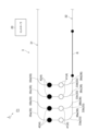
- FIG. 3 is a schematic plan view showing the first building side of the conveyance system in FIG. 1.
- FIG. 4 is a schematic plan view illustrating an example of approach control in the conveyance system of FIG. 1.
- FIG. 5 is a schematic plan view illustrating a continuation of FIG. 4.
- FIG. 6 is a schematic plan view illustrating an example of approach control in the conveyance system of FIG. 1.
- FIG. 7 is a schematic plan view illustrating a continuation of FIG. 6.
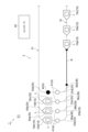
- FIG. 8 is a schematic plan view showing the first building side of the transport system according to the fourth embodiment.
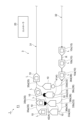
- FIG. 9 is a schematic plan view showing the first building side of the transport system according to the fifth embodiment.
- the transport system 1 is a system that performs point-to-point transport in which a transport source and a transport destination are patterned.
- the transport system 1 performs inter-building transport in which cargo is delivered between the first building F1 and the second building F2.
- the transport system 1 includes a plurality of transport vehicles 10 and a controller 20.
- the transport vehicle 10 travels along the track 3 and transports the load.
- the transport vehicle 10 is configured to be able to transfer loads.
- the guided vehicle 10 is an automatic guided vehicle that travels on the ceiling.
- the transport vehicle 10 is also referred to as, for example, a truck (transport vehicle), an overhead vehicle (overhead vehicle), or a traveling vehicle (traveling vehicle).
- the number of transport vehicles 10 included in the transport system 1 is, for example, about 50, and varies depending on the required transport amount and transport distance.
- the conveyance vehicle 10 includes a running cart 144, a power feeding cart 145 that receives power from the track 3, a ⁇ drive 147, and a lower part thereof for transversely transporting it with respect to the track 3.
- the transverse feed section 146 is provided.
- the ⁇ drive 147 controls the attitude of the load L by rotating the lift drive unit 148 in a horizontal plane.
- the elevating drive section 148 moves up and down the elevating platform 149 holding the load L, and transfers the load L to and from the delivery port 4.
- the lifting table 149 chucks the load L at the upper flange 124.
- the load L is, for example, a container that stores a plurality of semiconductor wafers, but may also be a glass substrate, general parts, or the like.
- the track 3 is laid, for example, on the ceiling.
- the track 3 is supported by struts 141.
- the track 3 is a predetermined travel path on which the transport vehicle 10 travels.
- Track 3 is a one-way road.
- the traveling direction (forward direction) of the transport vehicle 10 on the track 3 is determined to be one direction, and traveling in the opposite direction is prohibited.
- the track 3 has a closed track layout with no influence from outside the track 3.
- upstream and "downstream” correspond to "upstream” and "downstream” in the traveling direction of the transport vehicle 10, respectively.
- the track 3 includes main tracks 31 and 32, four first branch tracks 33a, 33b, 33c, and 33d that branch from the main track 32 and join the main track 31, and the main track 31. It includes four second branch tracks 34a, 34b, 34c, and 34d that branch from the main track 32 and merge with the main track 32.
- the main tracks 31 and 32 are tracks that span between the first building F1 and the second building F2.
- the length of the main tracks 31, 32 is, for example, 200 m.
- the main tracks 31 and 32 are surrounded and closed by a wall (not shown) between the first building F1 and the second building F2.
- the main tracks 31, 32, the first branch tracks 33a to 33d, and the second branch tracks 34a to 34d constitute a circular track on which the plurality of transport vehicles 10 travel.
- the first branch tracks 33a to 33d are arranged within the first building F1.
- the first branch tracks 33a to 33d extend in parallel.
- the first branch tracks 33a to 33d are provided in a comb shape between the main tracks 31 and 32 extending in parallel.
- the first branch tracks 33a to 33d are located upstream of the main track 31 (downstream of the main track 32) in this order.
- the second branch tracks 34a to 34d are arranged in the second building F2.
- the second branch tracks 34a to 34d extend in parallel.
- the second branch tracks 34a to 34d are provided in a comb shape between the main tracks 31 and 32 extending in parallel.
- the second branch tracks 34a to 34d are located upstream of the main track 32 (downstream of the main track 31) in this order.
- the locations where the first branch tracks 33a to 33d join the main track 31 are merging points 35a, 35b, 35c, and 35d.
- Each of the first branch tracks 33a to 33d is connected to the main track 31 via merging points 35a, 35b, 35c, and 35d, respectively.
- the track 3 has a plurality of merging points 35a to 35d arranged on the main track 31 at a distance from each other.
- the main track 31 merges from each of the first branch tracks 33a to 33d via mutually different merging points 35a, 35b, 35c, and 35d.
- the portion of the track 3 downstream of the merging point 35a is the main track 31, and that it joins from the first branch track 33a upstream thereof.
- the first branch tracks 33a to 33d are connected to the main track 31 through different merging points 35a to 35d, respectively.
- the merging points 35a to 35d are separated from each other by a predetermined distance on the main track 31.
- the locations where the first branch tracks 33a to 33d branch from the main track 32 are branch points 36a, 36b, 36c, and 36d.
- Each of the first branch tracks 33a to 33d is connected to the main track 32 via branch points 36a, 36b, 36c, and 36d, respectively. That is, the track 3 has branch points 36a to 36d, which are a plurality of branch points arranged on the main track 32 and spaced apart from each other.
- the main track 32 branches into first branch tracks 33a to 33d via mutually different branch points 36a, 36b, 36c, and 36d. Note that, for example, it is assumed that the portion of the track 3 upstream from the branch point 36a is the main track 32, and downstream thereof branches into the first branch track 33a.
- the first branch tracks 33a to 33d are connected to the main track 32 through different branch points 36a to 36d, respectively.
- the branch points 36a to 36d are separated from each other by a predetermined distance on the main track 32.
- a “merging point” is a point where a branch track connects to the main track.
- a “merging point” is a point where a branch track connects to the main track.
- a “merging point” is a connection point between the branch tracks and the main track to enter the main track.
- a “branch point” is a point where the main track connects to the branch track.
- a “branch point” is a point where a main track leads to a branch track.
- “Turnoff points” are these connection points for entry from the main track to the branch track.
- the main orbit 31 corresponds to the second main orbit
- the main orbit 32 corresponds to the first main orbit
- the first branch orbits 33a to 33d correspond to the branch orbits.
- Each of the first branch tracks 33a to 33d has a stop position corresponding to the delivery port 4 through which the transport vehicle 10 delivers the load L.
- the delivery ports 4 are arranged along each of the first branch tracks 33a to 33d.
- the delivery port 4 is provided, for example, on a conveyor (not shown) that conveys the load L.
- the delivery port 4 has an unloading port 41 and a loading port 42.
- the unloading port 41 is a port for unloading the load L from the transport vehicle 10. At the unloading port 41, the load L is unloaded from the time the load L is placed until the subsequent transport vehicle 10 arrives.
- the unloading port 41 is arranged upstream of the loading port 42 at a predetermined interval. In other words, the loading port 42 is arranged downstream of the unloading port 41 at a predetermined interval.
- the loading port 42 is a port for loading the load L onto the transport vehicle 10.
- the loading port 42 can carry the load L into the port over a span in which a plurality of transport vehicles 10 arrive in succession.
- the unloading port 41 and the loading port 42 are not particularly limited, and various known ports can be employed.
- the controller 20 is an electronic control unit that includes a CPU (Central Processing Unit), a ROM (Read Only Memory), a RAM (Random Access Memory), and the like.
- the controller 20 can be configured, for example, as software in which a program stored in a ROM is loaded onto a RAM and executed by a CPU.
- the controller 20 may be configured as hardware such as an electronic circuit.
- the controller 20 communicates with the plurality of guided vehicles 10 and controls the traveling of the plurality of guided vehicles 10 .
- the controller 20 controls the first branch track for each carrier 10 that is stopped at a stop position corresponding to each delivery port 4 of the first branch tracks 33a to 33d (here, a stop position corresponding to the loading port 42).
- Start control for starting toward the main track 31 is executed for each of the tracks 33a to 33d.
- the stop position corresponding to the loading port 42 may also be simply called a "stop position.”
- Upstream and downstream of the start control correspond to upstream and downstream of the main track 31
- upstream and downstream of the approach control correspond to upstream and downstream of the main track 32 .
- the guided vehicle 10 stopped on the first branch track 33 on the downstream side among the first branch tracks 33a to 33d is simultaneously or simultaneously with the guided vehicle 10 stopped on the first branch track 33 on the upstream side. launch it earlier than the Specifically, in the start control, the guided vehicle 10 stopped on the first branch track 33d is started at the same time as or earlier than the guided vehicle 10 stopped on the first branch track 33c.
- the guided vehicle 10 stopped on the first branch track 33c is started simultaneously with or earlier than the guided vehicle 10 stopped on the first branch track 33b.
- the guided vehicle 10 stopped on the first branch track 33b is started simultaneously with or earlier than the guided vehicle 10 stopped on the first branch track 33a.
- each stopped guided vehicle 10 is started ( (forced start).
- the pitch timer starts counting down from the reference pitch time in each of the first branch tracks 33a to 33d.
- the conveyance vehicle 10 stopped at the stop position is started, and the count of the pitch timer is reset to the reference pitch time.
- the pitch timer continues the countdown.
- the reference pitch time may be a predetermined fixed value or may be a variable value.
- the time axes of the pitch timers of the first branch tracks 33a to 33d are shifted so that the guided vehicle 10 stopped on the first branch track 33 on the downstream side starts first.
- the controller 20 executes approach control to cause each of the plurality of guided vehicles 10 traveling on the main track 32 to sequentially enter each of the first branch tracks 33a to 33d from the main track 32 in order from the downstream side to the upstream side. .
- the guided vehicle 10 enters the first branch track 33a, the next guided vehicle 10 enters the first branch track 33b, and the next guided vehicle 10 enters the first branch track 33c. Then, the next guided vehicle 10 is caused to enter the first branch track 33d, and thereafter, such approach of the guided vehicle 10 is repeated.
- destination determination control is performed to determine (guide) the destination of the guided vehicle 10 traveling in the specific section R upstream of each of the branch points 36a to 36d on the main track 32.
- the specific section R is a straight section close to each of the branch points 36a to 36d.
- the specific section R is not limited to a straight section, and may be a section including a curved line or various other sections.
- the specific section R is not particularly limited as long as it is upstream from each of the branch points 36a to 36d.
- the delivery port 4 here, any unloading port 41 of the first branch tracks 33a to 33d
- the controller 20 grasps the number of guided vehicles 10 present on each of the first branch tracks 33a to 33d (number of vehicles entering). Specifically, in the approach control, the controller 20 selects a transport vehicle 10 existing on any of the first branch tracks 33a to 33d corresponding to the transport destination at the timing when the transport destination is determined by the transport destination determination control described above. Increase the number of units by one (count up). In the start control, when the guided vehicle 10 that is stopped at any of the first branch tracks 33a to 33d is started, the controller 20 starts the guided vehicle 10 from any of the first branch tracks 33a to 33d at the timing of the start. The number of transport vehicles 10 existing in is reduced by one (countdown).
- the controller 20 performs the above-described start control and approach control for each guided vehicle group including a plurality of guided vehicles 10 (four in this case) corresponding to the number of first branch tracks 33a to 33d.
- Execute virtual connection control The controller 20 moves the plurality of guided vehicles 10 along the orbits (main orbits 31, 32, first branch orbits 33a to 33d, and second branch orbits 34a to 34d) so that the orbiting distance or the orbiting time is the same. Let it run.
- the controller 20 causes the guided vehicle 10 that has entered the first branch track 33d to enter the second branch track 34a, and causes the guided vehicle 10 that has entered the first branch track 33c to enter the second branch track 34b.
- the guided vehicle 10 that entered the first branch track 33b enters the second branch track 34c, and the guided vehicle 10 that entered the first branch track 33a enters the second branch track 34d.
- the guided vehicle 10 that has entered the second branch track 34d is caused to enter the first branch track 33a
- the guided vehicle 10 that has entered the second branch track 34c is caused to enter the first branch track 33b
- the guided vehicle 10 that has entered the second branch track 34b is caused to enter the first branch track 33c
- the guided vehicle 10 that has entered the second branch track 34a is caused to enter the first branch track 33d.
- the guided vehicles 10 are caused to approach the first branch tracks 33a to 33d from the main track 32 in a priority order according to the approach information regarding the approach state of each guided vehicle to the first branch tracks 33a to 33d.
- the delivery port 4 to which the transport vehicle 10 delivers the cargo is determined in a priority order according to the approach state.
- the transport vehicle 10 is caused to enter one of the first branch tracks 33a to 33d corresponding to the delivery port 4 determined in the transport destination determination control.
- approach information including information indicating the number of guided vehicles 10 existing on each of the first branch tracks 33a to 33d is acquired.
- the delivery port 4 of the first branch track 33 with the least number of existing transport vehicles 10 among the first branch tracks 33a to 33d is selected as the transport destination of the transport vehicle 10.
- the transport vehicle 10 is caused to enter the first branch track 33 corresponding to the determined transport destination. That is, in the approach control, the guided vehicle 10 is caused to enter the first branch track 33 where the number of guided vehicles 10 is the least among the first branch tracks 33a to 33d.
- the transport vehicle 10 is caused to enter the first branch track 33 corresponding to the determined transport destination.
- the transport vehicle 10 if there are a plurality of first branch tracks 33 with the smallest number of existing guided vehicles 10, the main track 32 among the plurality of first branch tracks 33 among the first branch tracks 33a to 33d.
- the carrier vehicle 10 enters the first branch track 33 corresponding to the branch point 36 located on the most downstream side.
- the guided vehicle 10 is made to wait on the main track 32 without entering the plurality of first branch tracks 33.
- the guided vehicle 10 parked on the main track 32 is controlled to enter at least one of the plurality of first branch tracks 33 to the first branch track 33a corresponding to the branch point 36a located on the most downstream side. It is started based on the timing when the number of existing transport vehicles 10 decreases (timing when the count of the pitch timer becomes 0).
- the countdown of the guided vehicle 10 existing on the first branch track 33a corresponding to the branch point 36a located on the most downstream side is used as a trigger to determine the destination of the guided vehicle 10 waiting on the main track 32. Start decision control.
- the set number is an arbitrary number set by the user, as long as it is equal to or less than the upper limit of the number of transport vehicles 10 that can exist on each first branch track 33.
- the set number of devices may be one or two or more devices.
- the number of guided vehicles 10 existing on the first branch track 33a may not decrease at the timing when the count of the pitch timer reaches 0.
- the guided vehicle 10 placed on standby on the main track 32 may start to enter at least one of the plurality of first branch tracks 33 .
- FIG. 4 is a schematic plan view for explaining an example of approach control in the transport system 1.
- FIG. 5 is a schematic plan view continuing from FIG. 4.
- the transport vehicles 10a to 10c are traveling close to a specific section R.
- Transport vehicles 10d to 10f are located at loading ports 42 of first branch tracks 33a to 33c, respectively. That is, the number of guided vehicles 10 existing on the first branch tracks 33a to 33c is one, and the number of guided vehicles 10 existing on the first branch track 33d is zero.
- the destination determination control selects the delivery port 4 of the first branch track 33d, where the number of existing guided vehicles 10 is the smallest (0), as the destination of the guided vehicle 10a. Determine as.
- the controller 20 counts up the number of guided vehicles 10 existing on the first branch track 33d.
- the guided vehicle 10a is caused to enter the first branch track 33d.
- the controller 20 counts up the number of transport vehicles 10 existing on the first branch track 33a.
- the guided vehicle 10b is caused to enter the first branch track 33a.
- the guided vehicle 10c is located in the specific section R, in the destination determination control, among the first branch tracks 33b to 33d in which the number of existing guided vehicles 10 is one, the most downstream of the main track 32.
- the delivery port 4 of the first branch track 33b corresponding to the branch point 36b located on the side is determined as the destination of the transport vehicle 10c.
- the controller 20 counts up the number of transport vehicles 10 existing on the first branch track 33b.
- the guided vehicle 10c is caused to enter the first branch track 33b.
- the guided vehicle 10a enters the first branch track 33d
- the guided vehicle 10b enters the first branch track 33a
- the guided vehicle 10c enters the first branch track 33b. be allowed to enter.
- FIG. 6 is another schematic plan view for explaining an example of approach control.
- FIG. 7 is a schematic plan view continuing from FIG. 6.
- the guided vehicles 10a to 10c are traveling within a specific section R approaching a plurality of branch points 36.
- a plurality of transport vehicles 10 are located at all of the unloading ports 41 and loading ports 42 of the first branch tracks 33a to 33d, respectively. That is, the number of transport vehicles 10 existing on each of the first branch tracks 33a to 33d is two.
- the following approach control is executed.
- the number of guided vehicles 10 existing on each of the first branch tracks 33a to 33d is the same as the set number, and the destination determination control does not determine the destination of the guided vehicle 10a.
- the approach control for example, when the guided vehicle 10a approaches the end of the specific section R, the guided vehicle 10a is decelerated and the guided vehicle 10a is made to wait on the main track 32.
- the guided vehicles 10 existing on each of the first branch tracks 33a to 33d start one by one one by one.
- the destination of the guided vehicle 10a is determined by destination determination control at the timing when the number of guided vehicles 10 existing on the first branch track 33a corresponding to the branch point 36a located on the most downstream side is reduced.
- the transport destination determination control among the first branch tracks 33a to 33d in which the number of existing transport vehicles 10 is the least, one, the first branch track corresponding to the branch point 36a located on the most downstream side of the main track 32 is The delivery port 4 of the branch track 33a is determined as the destination of the transport vehicle 10a.
- the controller 20 counts up the number of transport vehicles 10 existing on the first branch track 33a.
- the guided vehicle 10a is caused to enter the first branch track 33a.
- the transport destination of the transport vehicle 10b following the transport vehicle 10a is determined to be the delivery port 4 of the first branch track 33b.
- the guided vehicle 10b is caused to enter the first branch track 33b.
- the transport destination of the transport vehicle 10c following the transport vehicle 10b is determined to be the delivery port 4 of the first branch track 33c.
- the guided vehicle 10c is caused to enter the first branch track 33c.
- the transport system 1 causes the transport vehicles 10 to enter the first branch tracks 33 in the priority order according to the entry information regarding the entry state of each transport vehicle 10 to the plurality of first branch tracks 33.
- the guided vehicle 10 it becomes possible to cause the guided vehicle 10 to enter each of the plurality of first branch tracks 33 so as to prevent a situation where the guided vehicles 10 existing on a specific first branch track 33 are always in short supply.
- the approach information includes information indicating the number of transport vehicles 10 existing on each first branch track 33.
- the guided vehicle 10 is caused to enter the first branch track 33 with the least number of guided vehicles 10 among the plurality of first branch tracks 33 based on the approach information. In this case, it is possible to concretely prevent a situation where the number of guided vehicles 10 existing on a specific first branch track 33 is always insufficient.
- the first branch track 33 is located at the most downstream side of the main track 32 among the plurality of first branch tracks 33.
- the guided vehicle 10 is made to preferentially enter the first branch track 33a corresponding to the branch point 36a.
- the guided vehicle 10 can be moved more smoothly than when the guided vehicle 10 is preferentially entered into the first branch track 33 that branches from the upstream side of the main track 32 among the plurality of first branch tracks 33. It is possible to enter each branch track.
- the transport vehicle 10 is The vehicle 10 is prevented from interfering with the travel of another guided vehicle 10 following the guided vehicle 10, and the occurrence of traffic congestion is suppressed.
- a trouble or the like may occur on the first branch track 33 into which the guided vehicle 10b enters, and the guided vehicle 10b may not be able to enter.
- the guided vehicle 10b when the guided vehicle 10b enters the first branch track 33d branching from the upstream side of the main track 32, if the guided vehicle 10b stops upstream of the branch point 36, the guided vehicle 10b This may prevent the guided vehicle 10c immediately following the vehicle 10b from entering the first branch tracks 33a to 33c, and there is a risk that traffic congestion will occur on the main track 32.
- the guided vehicle 10b enters the first branch track 33a branching from the most downstream side of the main track 32. This allows the guided vehicle 10b to wait near the branch point 36a located on the most downstream side, and prevents the traveling of the guided vehicle 10c that immediately follows the guided vehicle 10b from being obstructed. As a result, the transport vehicle 10c can smoothly enter the first branch tracks 33b to 33d. From the above, the guided vehicle 10 can enter the first branch track 33 more smoothly, and the occurrence of traffic congestion on the main track 32 can be suppressed.
- the approach of the transport vehicle 10 that is parked on the main track 32 to at least one of the plurality of first branch tracks 33 is controlled by controlling the approach to at least one of the plurality of first branch tracks 33. It is started based on the timing when the number of transport vehicles 10 existing on one branch track 33 is reduced. This allows the guided vehicle 10 to enter the guided vehicle 10 more smoothly than when the guided vehicle 10 is preferentially entered into the first branch track 33 branching from the upstream side of the main track 32 among the plurality of first branch tracks 33. 1 branch track 33 can be entered.
- the track 3 has a main track 31.
- the plurality of first branch tracks 33 are connected to the main track 31 via mutually different merging points 35.
- the controller 20 executes a start control to start each guided vehicle 10 stopped at the stop position of each of the plurality of first branch tracks 33 toward the main track 31 for each of the plurality of first branch tracks 33 .
- the approach control at the timing when the destination of the guided vehicle 10 is determined, the number of guided vehicles 10 existing on the first branch track 33 corresponding to the destination is increased by one.
- the start control at the timing when the guided vehicle 10 is started on the first branch track 33, the number of guided vehicles 10 existing on the first branch track 33 is reduced by one. In this case, the above-mentioned effect that the transport vehicle 10 can smoothly transport the load can be specifically realized.
- the guided vehicle 10 is caused to enter the first branch track 33 where the number of guided vehicles 10 is the least among the first branch tracks 33a to 33d.
- each delivery port 4 of the first branch tracks 33a to 33d is determined (cyclically) in order from the downstream side to the upstream side of the main track 32 as the transfer destination of the guided vehicle 10,
- the transport vehicle 10 may sequentially enter the first branch track 33 of the determined transport destination.
- approach information including information regarding the first branch track 33 (approach branch track) into which the guided vehicle 10 (first guided vehicle) enters may be acquired.
- the delivery port 4 of the first branch track 33 corresponding to another branch point 36 may be determined as the transport destination of another transport vehicle 10 (second transport vehicle) immediately following the transport vehicle 10.
- another transport vehicle 10 may be caused to enter the first branch track 33 of the determined transport destination. That is, in the approach control, if there is another branch point 36 on the main track 32 adjacent to the upstream side of the branch point 36 of the first branch track 33 into which the guided vehicle 10 has entered, Another carrier vehicle 10 may enter the first branch track 33.
- the first branch track 33a corresponding to the branch point 36a located on the most downstream side of the main track 32 The delivery port 4 may be determined as the transport destination of another transport vehicle 10.
- another transport vehicle 10 may be caused to enter the first branch track 33 of the determined transport destination. That is, in the approach control, if another branch point 36 does not exist, another guided vehicle 10 may enter the first branch track 33a corresponding to the branch point 36a located on the most downstream side of the main track 32.
- the following entry control is executed.
- the conveyance destination determination control in the main track 32, another branch point 36d is adjacent to the upstream side of the branch point 36c of the first branch track 33c into which the guided vehicle 10f has entered.
- the delivery port 4 of the corresponding first branch track 33d is determined as the transport destination of the transport vehicle 10a that immediately follows the transport vehicle 10f.
- the guided vehicle 10a is caused to enter the first branch track 33d.
- the branch point 36 is located at the most downstream side of the main track 32.
- the delivery port 4 of the first branch track 33a corresponding to the branch point 36a is determined as the transport destination of the transport vehicle 10b.
- the guided vehicle 10b is caused to enter the first branch track 33a.
- the guided vehicle 10 enters the first branch tracks 33a to 33d in the order, and immediately after the guided vehicle 10 enters the first branch track 33d, the first branch track The carrier vehicle 10 enters the track 33a.
- the guided vehicle 10a is allowed to enter the first branch track 33d
- the guided vehicle 10b is allowed to enter the first branch track 33a
- the guided vehicle 10c is allowed to enter the first branch track 33b.
- the transport system 1 that executes the approach control according to the second embodiment, it is possible to have a plurality of transport vehicles 10 equally enter each of the first branch tracks 33. This suppresses a decrease in the number of guided vehicles 10 starting from the first branch tracks 33a to 33d, thereby suppressing a shortage in the number of guided vehicles 10 on the second branch tracks 34a to 34d. As a result, a decrease in the frequency of delivery of loads from the transport vehicle 10 to the delivery ports 4 provided along the second branch tracks 34a to 34d is suppressed, and therefore a reduction in transport capacity can be suppressed.
- the guided vehicle 10 may be caused to enter the first branch track 33 where the number of existing guided vehicles 10 is less than the set number, based on the acquired approach information. More specifically, in the destination determination control, the delivery port 4 of the first branch track 33 where the number of existing guided vehicles 10 is less than the set number is determined as the destination of the guided vehicle 10 based on the acquired approach information. You may. In the approach control, the guided vehicle 10 may be caused to enter the first branch track 33 of the determined destination.
- approach control according to the following third embodiment is executed.
- the delivery port 4 of the first branch track 33d where the number of existing guided vehicles 10 is 0, is determined as the destination of the guided vehicle 10a.
- the guided vehicle 10a is caused to enter the first branch track 33d.
- the set number of vehicles is 2, in the transport destination determination control, any of the delivery ports 4 of the first branch tracks 33a to 33d in which the number of existing transport vehicles 10 is one or less is selected for the transport of the transport vehicle 10a. Decide as the first step.
- the transport vehicle 10a is caused to enter the first branch track 33 of the determined transport destination.
- the guided vehicles 10 after the guided vehicles 10 are made to wait on the main track 32, a plurality of first branch tracks 33 in which the number of existing guided vehicles 10 is less than the set number are detected. If this occurs, the delivery port 4 of the first branch track 33 corresponding to the branch point 36 located on the most downstream side of the main track 32 among the plurality of first branch tracks 33 is the transfer destination of the guided vehicle 10 that is on standby. It may be determined as In the approach control, the guided vehicle 10 may be caused to enter the determined destination.
- the carrier vehicle 10 may enter the first branch track 33 corresponding to the branch point 36 located on the most downstream side of the main track 32 .
- approach control according to the following third embodiment is executed.
- the delivery port 4 of the first branch track 33a corresponding to the branch point 36a located on the most downstream side of the main track 32 among the first branch tracks 33a to 33d is placed on standby in the main track 32. It is determined as the transport destination of the transported transport vehicle 10a.
- the transport vehicle 10a is caused to enter the determined transport destination.
- the guided vehicle 10 is caused to enter the first branch track 33 where the number of existing guided vehicles 10 is less than the set number, based on the approach information.
- the guided vehicles 10 are made to wait on the main track 32. Thereby, it is possible to avoid a situation in which the guided vehicles 10 enter a specific first branch track 33 in a concentrated manner.
- more guided vehicles 10 than the number of vehicles that can enter each first branch track 33 is suppressed from entering, it is possible to suppress the occurrence of traffic jams on the first branch track 33. As a result, it is possible to suppress a decrease in the amount of conveyance in the conveyance system.
- the waiting guided vehicle 10 enters the first branch track 33a corresponding to the branch point 36a located on the most downstream side of the main track 32 among the branch tracks 33.
- the guided vehicle 10 can be moved more smoothly than when the guided vehicle 10 is preferentially entered into the first branch track 33 that branches from the upstream side of the main track 32 among the plurality of first branch tracks 33.
- the first branch track 33 can be entered.
- FIG. 8 is a schematic plan view showing a transport system 101 according to the fourth embodiment.
- the transport system 101 according to the fourth embodiment has a track 103 instead of the track 3 (see FIG. 3).
- the track 103 includes main tracks 31 and 32, a first branch track 33, a second branch track 34, and a backup branch track 133.
- the reserve branch track 133 is connected to the main track 32 via a reserve branch point 136, which is another branch point located downstream of the plurality of branch points 36a to 36d.
- the preliminary branch track 133 is connected to the main track 31 via a preliminary junction 135, which is another junction located upstream of the plurality of junctions 35a to 35d.
- a preliminary junction 135 is another junction located upstream of the plurality of junctions 35a to 35d.
- the main track 32 branches into a reserve branch track 133 via a reserve branch point 136.
- the portion of the track 103 upstream from the preliminary branch point 136 is the main track 32, and that it branches into the preliminary branch track 133 downstream thereof.
- the conveyance vehicle 10 scheduled to enter is made to enter the preliminary branch track 133 instead of the first branch track 33.
- the preliminary merging point 135 is a predetermined distance away from the merging point 35a.
- the preliminary branch point 136 is a predetermined distance away from the branch point 36a.
- the delivery port 4 is arranged along the preliminary branch line track 133. Thereby, it becomes possible to transfer loads on the spare branch track 133, so that it becomes possible to further suppress a decrease in the transport capacity of the transport system 1.
- FIG. 9 is a schematic plan view showing a transport system 201 according to the fifth embodiment.
- the transport system 201 according to the fifth embodiment has a track 203 instead of the track 3 (see FIG. 3).
- the track 203 includes main tracks 31 and 32, a first branch track 33, a second branch track 34, a backup branch track 133, and an auxiliary branch track 237.
- the auxiliary branch track 237 is connected to the main track 31 via an auxiliary branch point 236, which is a branch point located downstream of the plurality of merging points 35. That is, the main track 31 branches into an auxiliary branch track 237 via an auxiliary branch point 236.
- the auxiliary branch track 237 is connected to the main track 32 via an auxiliary merging point 235, which is a merging point located upstream of the plurality of branch points 36.
- the transport vehicle 10 that has entered the preliminary branch track 133 may enter the auxiliary branch track 237 in the approach control.
- the transport vehicle 10 that has entered the preliminary branch track 133 may enter the auxiliary branch track 237 in the approach control.
- the transport vehicle 10 that has entered the preliminary branch track 133 may enter the auxiliary branch track 237 in the approach control.
- the transport vehicles 10 that are not transporting the load L are transferred to the auxiliary branch track 237. This bias can be eliminated by entering the area.
- the preliminary branch line track 133 and the auxiliary branch line track 237 described above may also be provided on the second building F2 side.
- the track 3 includes four first branch tracks 33a to 33d, but the number of first branch tracks may be two, three, or five or more.
- the track 3 includes four second branch tracks 34a to 34d, the number of second branch tracks may be two, three, or five or more.
- the vehicle in the start control, the vehicle is forced to start at a constant cycle regardless of whether or not the load L is loaded, but the vehicle may be started on the condition that the load L is loaded.
- the destination determination control is executed to determine the destination of the guided vehicle 10 traveling in the specific section R. However, the destination determination control does not need to be executed, and can be performed at the delivery port of the destination at any timing. 4 may be determined.
- virtual connection control is performed for each transport vehicle group including a plurality of transport vehicles 10, but virtual connection control does not need to be performed.
- the guided vehicle 10 when the guided vehicle 10 is caused to enter the first branch track 33 corresponding to the transport destination, a trouble occurs in the first branch track 33, and the guided vehicle 10 is moved to the first branch track 33. There are cases where it is not possible to enter (when the first branch track 33 is down). In this case, in the approach control, the guided vehicle 10 may be caused to enter the first branch track 33 corresponding to another branch point 36 adjacent to the upstream side of the branch point 36 of the first branch track 33. Note that if the branch point 36 of the first branch track 33 where the trouble has occurred is the branch point 36 located on the most upstream side of the main track 32, the guided vehicle 10 may be made to wait on the main track 32.
- the configurations in the above embodiments are not limited to the shapes described above, and various shapes can be applied. Each configuration in each embodiment can be arbitrarily applied to each configuration in other embodiments. Some of the configurations in the above embodiments can be omitted as appropriate without departing from the gist of one aspect of the present invention.
Landscapes
- Control Of Position, Course, Altitude, Or Attitude Of Moving Bodies (AREA)
Abstract
Description
Claims (10)
- 軌道に沿って走行し、荷を搬送する複数の搬送車と、
複数の前記搬送車の走行を制御するコントローラと、を備えた搬送システムであって、
前記軌道は、第1主軌道と、互いに異なる分岐点を介して前記第1主軌道から分岐する複数の支線軌道と、を有し、
前記コントローラは、前記第1主軌道から複数の前記支線軌道のそれぞれに前記搬送車を進入させる進入制御を実行し、
前記進入制御では、各搬送車の複数の前記支線軌道への進入状態に関する進入情報に応じた優先順序で、前記支線軌道に前記搬送車を進入させる、搬送システム。 - 前記進入情報は、各支線軌道に存在する前記搬送車の台数を示す情報を含み、
前記進入制御では、
前記進入情報に基づいて、複数の前記支線軌道のうち存在する前記搬送車の台数が最も少ない支線軌道に、前記搬送車を優先的に進入させる、請求項1に記載の搬送システム。 - 前記進入制御では、
存在する前記搬送車の台数が最も少ない前記支線軌道が複数存在する場合、当該複数の支線軌道のうち前記第1主軌道の最も下流側に位置する前記分岐点に対応する前記支線軌道に、前記搬送車を進入させる、請求項2に記載の搬送システム。 - 前記進入情報は、第1搬送車が進入する進入支線軌道に関する情報を含み、
前記進入制御では、
前記第1主軌道において前記進入支線軌道の前記分岐点より上流側に隣接する別の前記分岐点が存在する場合、前記別の分岐点に対応する前記支線軌道に、前記第1搬送車の直後に後続する第2搬送車を進入させ、
前記別の分岐点が存在しない場合、前記第1主軌道の最も下流側に位置する前記分岐点に対応する前記支線軌道に、前記第2搬送車を進入させる、請求項1に記載の搬送システム。 - 前記進入情報は、各支線軌道に存在する前記搬送車の台数を示す情報を含み、
前記進入制御では、
前記進入情報に基づいて、存在する前記搬送車の台数が設定台数未満の前記支線軌道に前記搬送車を進入させ、
存在する前記搬送車の台数が前記設定台数未満の前記支線軌道が存在しない場合、前記搬送車を複数の前記支線軌道に進入させずに前記第1主軌道に待機させる、請求項1に記載の搬送システム。 - 前記進入制御では、
前記搬送車を前記第1主軌道に待機させた後に、存在する前記搬送車の台数が設定台数未満の前記支線軌道が複数生じた場合、当該複数の支線軌道のうち前記第1主軌道の最も下流側に位置する前記分岐点に対応する前記支線軌道に、待機させた前記搬送車を進入させる、請求項5に記載の搬送システム。 - 前記進入制御では、
前記第1主軌道に待機させた前記搬送車についての複数の前記支線軌道の少なくとも何れかへの進入を、最も下流側に位置する前記分岐点に対応する前記支線軌道に存在する前記搬送車の台数が減ったタイミングに基づいて開始させる、請求項5又は6に記載の搬送システム。 - 前記軌道は、第2主軌道を有し、
複数の前記支線軌道は、互いに異なる合流点を介して前記第2主軌道に繋がり、
前記コントローラは、複数の前記支線軌道のそれぞれの停止位置に停止した各搬送車を、複数の前記支線軌道ごとに前記第2主軌道へ向けて発進させる発進制御を実行し、
前記進入制御では、前記搬送車の搬送先を決定したタイミングで、当該搬送先に対応する前記支線軌道に存在する前記搬送車の台数を1台増やし、
前記発進制御では、前記搬送車を前記支線軌道において発進させたタイミングで、当該支線軌道に存在する前記搬送車の台数を1台減らす、請求項2~6の何れか一項に記載の搬送システム。 - 前記軌道は、第2主軌道と、予備支線軌道とを有し、
複数の前記支線軌道は、互いに異なる合流点を介して前記第2主軌道に繋がり、
前記予備支線軌道は、複数の前記分岐点より下流側に位置する別の分岐点である予備分岐点を介して前記第1主軌道から分岐し、複数の前記合流点より上流側に位置する別の合流点である予備合流点を介して前記第2主軌道に繋がり、
前記進入制御では、複数の前記支線軌道の少なくとも何れかにおいて前記荷の移載が不可能である場合、前記荷の移載が不可能な支線軌道に進入予定の前記搬送車を当該支線軌道に代えて前記予備支線軌道に進入させる、請求項1に記載の搬送システム。 - 前記軌道は、補助支線軌道を有し、
前記補助支線軌道は、複数の前記合流点より下流側に位置する分岐点である補助分岐点を介して前記第2主軌道から分岐し、複数の前記分岐点より上流側に位置する合流点である補助合流点を介して前記第1主軌道に繋がり、
前記進入制御では、前記予備支線軌道に進入させた前記搬送車を前記補助支線軌道に進入させる、請求項9に記載の搬送システム。
Priority Applications (2)
| Application Number | Priority Date | Filing Date | Title |
|---|---|---|---|
| CN202380036059.3A CN119096211A (zh) | 2022-06-06 | 2023-04-24 | 搬运系统 |
| JP2024526284A JP7841590B2 (ja) | 2022-06-06 | 2023-04-24 | 搬送システム |
Applications Claiming Priority (2)
| Application Number | Priority Date | Filing Date | Title |
|---|---|---|---|
| JP2022-091662 | 2022-06-06 | ||
| JP2022091662 | 2022-06-06 |
Publications (1)
| Publication Number | Publication Date |
|---|---|
| WO2023238533A1 true WO2023238533A1 (ja) | 2023-12-14 |
Family
ID=89118004
Family Applications (1)
| Application Number | Title | Priority Date | Filing Date |
|---|---|---|---|
| PCT/JP2023/016149 Ceased WO2023238533A1 (ja) | 2022-06-06 | 2023-04-24 | 搬送システム |
Country Status (4)
| Country | Link |
|---|---|
| JP (1) | JP7841590B2 (ja) |
| CN (1) | CN119096211A (ja) |
| TW (1) | TW202404840A (ja) |
| WO (1) | WO2023238533A1 (ja) |
Citations (3)
| Publication number | Priority date | Publication date | Assignee | Title |
|---|---|---|---|---|
| JPH10275017A (ja) * | 1997-03-31 | 1998-10-13 | Hitachi Ltd | 搬送制御方法および搬送装置 |
| WO2010035411A1 (ja) * | 2008-09-26 | 2010-04-01 | 村田機械株式会社 | 搬送車システム |
| JP6935846B2 (ja) * | 2018-05-01 | 2021-09-15 | 村田機械株式会社 | 搬送システム |
Family Cites Families (2)
| Publication number | Priority date | Publication date | Assignee | Title |
|---|---|---|---|---|
| GB2110448B (en) * | 1981-09-04 | 1986-01-22 | Plessey Co Plc | Material handling and sorting system |
| JP2005092823A (ja) * | 2003-09-19 | 2005-04-07 | Sharp Corp | 搬送車の管理方法 |
-
2023
- 2023-04-24 JP JP2024526284A patent/JP7841590B2/ja active Active
- 2023-04-24 CN CN202380036059.3A patent/CN119096211A/zh active Pending
- 2023-04-24 WO PCT/JP2023/016149 patent/WO2023238533A1/ja not_active Ceased
- 2023-05-25 TW TW112119429A patent/TW202404840A/zh unknown
Patent Citations (3)
| Publication number | Priority date | Publication date | Assignee | Title |
|---|---|---|---|---|
| JPH10275017A (ja) * | 1997-03-31 | 1998-10-13 | Hitachi Ltd | 搬送制御方法および搬送装置 |
| WO2010035411A1 (ja) * | 2008-09-26 | 2010-04-01 | 村田機械株式会社 | 搬送車システム |
| JP6935846B2 (ja) * | 2018-05-01 | 2021-09-15 | 村田機械株式会社 | 搬送システム |
Also Published As
| Publication number | Publication date |
|---|---|
| JPWO2023238533A1 (ja) | 2023-12-14 |
| TW202404840A (zh) | 2024-02-01 |
| CN119096211A (zh) | 2024-12-06 |
| JP7841590B2 (ja) | 2026-04-07 |
Similar Documents
| Publication | Publication Date | Title |
|---|---|---|
| JP6935846B2 (ja) | 搬送システム | |
| KR102586754B1 (ko) | 반송차 시스템 | |
| JP4766111B2 (ja) | 搬送車システム | |
| US12187548B2 (en) | Article transport facility | |
| WO2018110178A1 (ja) | 走行車システム | |
| WO2023238533A1 (ja) | 搬送システム | |
| JP7548167B2 (ja) | 物品収容設備 | |
| JP7790565B2 (ja) | 搬送システム | |
| KR20250086593A (ko) | 물품을 운송하기 위한 방법 및 시스템 | |
| JP2000330634A (ja) | 搬送システム | |
| JP2000353015A (ja) | 自動搬送システムの空車の追出し制御方法 | |
| JP2010066965A (ja) | 搬送システム | |
| JP7501474B2 (ja) | 物品収容設備 | |
| JP7501473B2 (ja) | 物品収容設備 | |
| JP5229622B2 (ja) | 搬送車システム | |
| JP2002332105A (ja) | 無人搬送車システム | |
| WO2024070146A1 (ja) | 搬送車システム | |
| JP3995085B2 (ja) | ループ搬送システム | |
| JP2000075926A (ja) | 自動搬送システムにおける配車制御方法 | |
| JP2004283994A (ja) | 搬送制御システム |
Legal Events
| Date | Code | Title | Description |
|---|---|---|---|
| 121 | Ep: the epo has been informed by wipo that ep was designated in this application |
Ref document number: 23819520 Country of ref document: EP Kind code of ref document: A1 |
|
| WWE | Wipo information: entry into national phase |
Ref document number: 202380036059.3 Country of ref document: CN |
|
| WWE | Wipo information: entry into national phase |
Ref document number: 2024526284 Country of ref document: JP |
|
| NENP | Non-entry into the national phase |
Ref country code: DE |
|
| 122 | Ep: pct application non-entry in european phase |
Ref document number: 23819520 Country of ref document: EP Kind code of ref document: A1 |