WO2023238335A1 - 磁気ギヤ - Google Patents
磁気ギヤ Download PDFInfo
- Publication number
- WO2023238335A1 WO2023238335A1 PCT/JP2022/023312 JP2022023312W WO2023238335A1 WO 2023238335 A1 WO2023238335 A1 WO 2023238335A1 JP 2022023312 W JP2022023312 W JP 2022023312W WO 2023238335 A1 WO2023238335 A1 WO 2023238335A1
- Authority
- WO
- WIPO (PCT)
- Prior art keywords
- section
- poles
- magnetic
- pole
- magnetic gear
- Prior art date
- Legal status (The legal status is an assumption and is not a legal conclusion. Google has not performed a legal analysis and makes no representation as to the accuracy of the status listed.)
- Ceased
Links
Images


Classifications
-
- H—ELECTRICITY
- H02—GENERATION; CONVERSION OR DISTRIBUTION OF ELECTRIC POWER
- H02K—DYNAMO-ELECTRIC MACHINES
- H02K49/00—Dynamo-electric clutches; Dynamo-electric brakes
- H02K49/10—Dynamo-electric clutches; Dynamo-electric brakes of the permanent-magnet type
- H02K49/102—Magnetic gearings, i.e. assembly of gears, linear or rotary, by which motion is magnetically transferred without physical contact
Definitions
- Typical rotating electric machines which are composed of permanent magnets and soft magnetic materials, have a higher rotational speed, an increased induced voltage, and a lower input voltage that can be used for torque output, resulting in a decrease in torque and iron loss.
- a decrease in efficiency occurs due to an increase in . Therefore, in order to obtain desired output and efficiency characteristics, it is common to configure a drive unit that combines a rotating electrical machine and gears so that the rotational speed of the rotating electrical machine falls within an appropriate range.
- the structure in which the permanent magnets are continuously skewed in the axial direction requires special manufacturing equipment to create the permanent magnets in a special shape and to combine them with the rotor core. There was a problem of increased costs.
- a method of configuring the number of poles of the magnetic gear such that the order of cogging torque becomes high can be considered.
- the present application was made in order to solve the above-mentioned problems, and aims to obtain a magnetic flux modulation type magnetic gear that achieves both reduction of cogging torque and reduction of electromagnetic excitation force without increasing manufacturing cost.
- the purpose is
- the magnetic gear disclosed in the present application includes a multi-pole mechanism in which a first number of magnetic poles made of permanent magnets are arranged along the circumferential direction, and a second number of magnetic poles made of permanent magnets that is smaller than the first number of poles.
- a small-pole mechanism arranged along the circumferential direction and a third number of magnetic poles made of soft magnetic material are arranged along the circumferential direction through a magnetic gap to each of the magnetic poles of the multi-pole mechanism and the magnetic poles of the small-pole mechanism.
- a magnetic gear section configured to share the functions of the stator, the first rotor, and the second rotor; a first shaft responsible for transmitting torque between the second rotor and the outside; and a second shaft responsible for transmitting torque between the second rotor and the outside;
- the position of the magnetic pole between the multi-pole mechanism, the small-pole mechanism, and the pole piece such that at least one of the multi-pole mechanism, the small-pole mechanism, and the pole piece has a phase difference between the sections. relationships are different, and at least one of the greatest common divisor of the first pole number and the third pole number and the greatest common divisor of the second pole number and the third pole number is 1 or 2. It is characterized by
- FIG. 2 is a cross-sectional view along the rotation axis showing the configuration of the magnetic gear according to the first embodiment.
- 2A and 2B are cross-sectional views perpendicular to the rotation axis of the first section and the second section, respectively, of a two-stage magnetic gear portion constituting the magnetic gear according to the first embodiment.
- 3A and 3B are diagrams showing the relationship between the electromagnetic excitation force be.
- FIG. 3 is a vector diagram of electromagnetic excitation force generated in the multipolar mechanism in the first section and the second section of the magnetic gear according to the first embodiment.
- FIG. 5A and 5B are a sectional view perpendicular to the rotation axis of the second section of the magnetic gear and a vector diagram of the electromagnetic excitation force generated in the multipolar mechanism, respectively, according to a modification of the first embodiment.
- 6A and 6B are diagrams showing the relationship between the circumferential position of the multipole mechanism of the magnetic gear and the first-order component of the electromagnetic excitation force according to a modification of the first embodiment, and the phase difference between the two sections and the magnetic It is a figure which shows the relationship with the amplitude of the electromagnetic excitation force primary component of the whole gear part.
- FIG. 3 is a cross-sectional view taken along a rotation axis and showing the configuration of a magnetic gear according to a second embodiment.
- FIG. 7 is a cross-sectional view perpendicular to the rotation axis of the second section of the magnetic gear according to the second embodiment.
- 9A and 9B are diagrams showing the relationship between the electromagnetic excitation force be.
- FIG. 7 is a cross-sectional view taken along a rotation axis and showing the configuration of a magnetic gear according to a third embodiment.
- FIG. 7 is a cross-sectional view taken along a rotation axis and showing the configuration of a magnetic gear according to a fourth embodiment.
- FIG. 7 is a cross-sectional view taken along a rotation axis and showing the configuration of a magnetic gear according to a fifth embodiment.
- FIG. 7 is a cross-sectional view along the rotation axis showing the configuration of a magnetic gear according to a sixth embodiment.
- FIG. 14A and 14B are cross-sectional views perpendicular to the rotation axis of the first section and the second section, respectively, of a two-stage magnetic gear portion constituting the magnetic gear according to the sixth embodiment.
- FIG. 9 is a diagram showing the relationship between the circumferential position in the magnetic gap between the multipole mechanism of the magnetic gear and the pole piece and the second-order component of the electromagnetic excitation force according to the sixth embodiment.
- 16A and 16B are diagrams showing the relationship between the circumferential position and the second-order component of electromagnetic excitation force in the magnetic gap between the multipole mechanism of the magnetic gear and the pole piece according to a modification of the sixth embodiment, respectively, and FIG. FIG.
- Embodiment 1. 1 to 4 are for explaining the configuration and operation of the magnetic gear according to the first embodiment
- FIG. 1 is a sectional view along the rotation axis including the rotation axis showing the configuration of the magnetic gear.
- 2A is a sectional view perpendicular to the rotation axis corresponding to line AA in FIG. 1 of the first section of a two-stage magnetic gear unit with different specifications in the axial direction
- FIG. 2B is a cross-sectional view of the second section B-- in FIG.
- FIG. 3 is a cross-sectional view perpendicular to the rotation axis corresponding to line B;
- Fig. 1 in order to emphasize the part of the magnetic gear made of magnetic material that generates the gear action, other elements are drawn without hatching even though they are cross-sections. , the cross-sectional view along the axis of rotation is drawn similarly.
- FIG. 3A shows the electromagnetic excitation force X component (PU unit) of the first section, the second section, and the entire gear section with respect to the rotation angle in electrical angle based on the multipole mechanism in the magnetic gear section.
- FIG. 4 is a vector diagram of the electromagnetic excitation force generated in the multipolar mechanism in the first section and the second section.
- the magnetic gear of the present application has two rotors and one stator as a magnetic flux modulation type magnetic gear, each of which has a multi-pole mechanism, a few-pole mechanism, and a pole piece. handle.
- a small-pole mechanism 2 which is a first rotor
- a multi-pole mechanism 4 which is a second rotor
- the magnetic gear section 5 is configured by concentrically arranging the pole piece 3, which is a stator, in the gap.
- the multi-pole mechanism 4, the few-pole mechanism 2, and the pole piece 3 are mechanically connected in the rotation axis X direction (axial direction).
- the arrangement of the three mechanisms (multi-pole mechanism 4, small-pole mechanism 2, pole piece 3) in the first section 5a and the arrangement of the three mechanisms in the second section 5b are such that at least one of the three mechanisms is The phase relationship of the mechanisms is set to be different between the first section 5a and the second section 5b.
- the magnetic gear portion 5 forms a step skew between the first section 5a and the second section 5b, but the circumferential arrangement of the multi-pole mechanism 4, the few-pole mechanism 2, and the pole piece 3 is The detailed configuration will be described later.
- the rotors of the magnetic gear 1 are each supported by a plurality of bearings 9.
- the portion (hatched) made of a magnetic material that generates a gear action is protected by a bracket 8b and a frame 8f made of structural members such as iron and non-magnetic material.
- the magnetic gear 1 includes a multi-pole mechanism 4 equipped with a permanent magnet, a small-pole mechanism 2 having fewer poles than the multi-pole mechanism 4, and a pole made of a soft magnetic material arranged with respect to them via a magnetic gap. It is constructed by arranging pieces 3 concentrically.
- Permanent magnets 4m and 2m which serve as magnetic poles, are magnetized in the radial direction, and similar to rotating electric machines, the polarity of permanent magnets adjacent to each other in the circumferential direction is reversed (N, S, N, S,... ⁇ :Arrow in the figure)
- the greatest common divisor of the number of poles Np2 in the few pole mechanism 2 and the number Np3 of poles in the pole piece 3, and the greatest common divisor of the number of poles Np4 in the multi pole mechanism 4 and the number of poles Np3 in the pole piece 3 are both 1. be.
- the order of the cogging torque in the small pole mechanism 2 or the pole piece 3 can be increased, which is determined by the least common multiple of the number of poles Np2 in the small pole mechanism 2 and the number Np3 of poles in the pole piece 3.
- the order of the cogging torque in the multipolar mechanism 4 or the pole piece 3, which is determined by the least common multiple of the number of poles Np4 in the multipolar mechanism 4 and the number Np3 in the pole piece 3, can also be increased.
- the spatial symmetry is one period in mechanical angle (first order spatial order)
- the electromagnetic excitation force of first order spatial order is multipolar mechanism 4 and few pole mechanism 2. and pole piece 3 respectively.
- the first-order spatial order electromagnetic excitation force causes the bearing 9 or the frame 8f to vibrate at a low frequency, which causes an increase in noise and vibration. It can be reduced by connecting in the axial direction to form the magnetic gear part 5. Details regarding this will be described later.
- the permanent magnets 2m and 4m used in each section have all surfaces extending in the axial direction in the axial direction. , and the shape is simplified (in this embodiment, it has a tile shape). Therefore, unlike the case where a continuous skew is formed, mass production is easy and manufacturing costs can be reduced.
- a line segment La is defined as a reference position in the circumferential direction in the first section 5a of FIG. 2A.
- the line segment La is an arbitrary position in the circumferential direction at the time when the multi-pole mechanism 4, the small-pole mechanism 2, and the pole piece 3 have the positional relationship (phase relationship) shown in FIG. 2A in the first section 5a. indicates the direction.
- the direction directly above the drawing is defined as a line segment La.
- the arrangement of the multi-pole mechanism 4, the small-pole mechanism 2, and the pole piece 3 in the second section 5b at the same time as when the first section 5a is arranged as shown in FIG. 2A is as shown in FIG. 2B.
- the second section 5b has a configuration in which the arrangement of the first section 5a is reversed by 180 degrees from the line segment La to the line segment Lb.
- the phases of the multi-pole mechanism 4, the small-pole mechanism 2, and the pole piece 3 are compared with the first section 5a, the phases of the multi-pole mechanism 4 match and they are arranged in the same manner.
- the small pole mechanism 2 and the pole piece 3 have different phases and different cross-sectional shapes.
- the multipolar mechanism 4 forms a step skew between the first section 5a and the second section 5b.
- a mechanism whose phase matches that of the first section 5a does not need to be stacked in the axial direction with a phase shift, and can be shared with the first section 5a, eliminating the need for manufacturing equipment for stacking with a phase shift. Increase in manufacturing costs can be suppressed.
- This effect is generally obtained by arranging two or more sections in the axial direction in which at least one of the pole piece 3, the small-pole mechanism 2, and the multi-pole mechanism 4 has a different phase.
- FIG. 3A and FIG. 3B The X component and Y component of the electromagnetic excitation force generated in the multipolar mechanism 4 of each of the first section 5a and the second section 5b constituting the magnetic gear part 5 of the magnetic gear 1 according to the first embodiment are shown in FIG. 3A and FIG. It becomes as shown in 3B. It can be seen that when the magnetic pole of the multi-pole mechanism 4 is rotated for one period (360 degrees) in electrical angle, it has a component that vibrates at the same period in the X-axis direction and the Y-axis direction.
- an electromagnetic excitation force of one period (spatial order 1) in mechanical angle with respect to the circumferential direction of the multipolar mechanism 4 is generated in each of the first section 5a and the second section 5b.
- the phase of the electromagnetic excitation force of the first spatial order is also rotated by 180 degrees, and as shown in the figure, the X component The phase is inverted for each of the and Y components.
- FIGS. 3A and 3B The relationship between the X component and the Y component at a rotation angle of 120° in FIGS. 3A and 3B is expressed in a vector diagram as shown in FIG. 4.
- FIG. 4 the trajectories of the first section 5a and second section 5b vectors are shown by solid lines and dotted lines, respectively.
- the vector of the electromagnetic excitation force at a rotation angle of 120° is reversed by 180° between the first section 5a and the second section 5b. Therefore, when added together (magnetic gear section 5), it becomes almost 0, and it can be seen that the electromagnetic excitation force is canceled by the electromagnetic force whose vector is reversed with the same magnitude and is not generated.
- the electromagnetic excitation force of the first section 5a and the second section 5b rotates along the locus while maintaining a 180° phase relationship, the electromagnetic excitation force is generated during one rotation of one period of electrical angle. It can be seen that the suppressive effect is maintained. That is, the effect of suppressing the electromagnetic excitation force is maintained even during one revolution of one mechanical angle period (in this embodiment, the number of poles Np4 is 28, so 14 electrical angle periods).
- This modification is the same as that described in Embodiment 1 except that the arrangement in the second section is different, and the arrangement in the first section is as explained in FIG. 2A.
- the relationship between the vectors of the electromagnetic excitation force is such that the first section 5a and the second section 5b have a phase difference ⁇ . It can be seen that the electromagnetic excitation force of the entire magnetic gear section 5, which is represented by the summed vector, varies depending on the phase difference between the first section 5a and the second section 5b.
- FIG. 6A shows the relationship between the first-order components of the electromagnetic excitation force, which is shown by adding vectors, and the distribution of the electromagnetic force at the circumferential position of the multipole mechanism 4. Similar to the notation in the vector diagram, the amplitude of the waveform (5: broken line) indicating the addition of the spatial first-order components of the electromagnetic excitation force may vary depending on the phase difference between the first section 5a and the second section 5b. Recognize.
- the second section 5b is arranged when rotated by 30 degrees in electrical angle with respect to the first section 5a explained in FIG. 2A with reference to the multipolar mechanism 4. I'm trying to make it happen.
- Lb4 is the direction in which the multi-pole mechanism 4 rotates from the line segment La when the time for rotating by 30 degrees in electrical angle with the multi-pole mechanism 4 as a reference has passed
- Lb4 is the direction in which the small-pole mechanism 2 rotates from the line segment La. The direction thus obtained is defined as a line segment Lb2.
- the second section 5b is configured to have the arrangement at the time when it rotates by 30 degrees in electrical angle with respect to the arrangement of the first section 5a when the multipolar mechanism 4 is referenced. There is no limit. It is clear that the same effect can be obtained even if the second section 5b is configured to have a position at a time when it rotates by another electrical angle so that vibrations due to electromagnetic excitation force can be canceled out. be.
- Embodiment 5 a magnetic gap portion is provided between the sections as in the fourth embodiment, with respect to the magnetic gear section described in the third embodiment, in which the three sections are arranged in a row.
- FIG. 12 is a cross-sectional view taken along a rotation axis including the rotation axis of the magnetic gear, for explaining the configuration and operation of the magnetic gear according to the fifth embodiment. Note that the arrangement of mechanisms in each of the first section, second section, and third section is the same as that described in Embodiment 3, and the explanation will be omitted and FIGS. 2A to 9B will be referred to.
- the magnetic gear 1 according to the fifth embodiment has a magnetic transmission between the first section 5a, the second section 5b, and the third section 5c in the axial direction through air or a non-magnetic material.
- This embodiment is the same as the third embodiment except that a target gap 5g is provided.
- a target gap 5g is provided.
- FIG. 12 shows an example in which a small magnetic gap 5g is provided in the axial direction in order to keep the volume of the magnetic gear 1 small
- the present invention is not limited to this. The same effect can be obtained even if the first section 5a, the second section 5b, and the third section 5c are spaced further apart in the axial direction, and the magnetic gap 5g is secured by connecting them with a structural member. is obtained.
- first section 5a, the second section 5b, and the third section 5c are made up of separate structural members, and the respective rotors (in this example, the multi-pole mechanism 4 and the few-pole mechanism 2) are connected by the structural members. It may also be a configuration. Also, as in the third embodiment, an example was shown in which sections with two types of arrangement patterns are connected in the axial direction, but more types of sections are combined to generate electromagnetic excitation force by adding vectors. A similar effect can be obtained by using a configuration that cancels out the noise.
- Embodiment 6 In the magnetic gear according to the sixth embodiment, an example will be described in which the magnetic gear portion is configured with a combination of polarities different from those in the first to fifth embodiments.
- 13 to 15 are for explaining the configuration and operation of the magnetic gear according to the sixth embodiment, and FIG. 13 is a sectional view along the rotation axis including the rotation axis showing the configuration of the magnetic gear.
- 14A is a sectional view perpendicular to the rotation axis of the first section corresponding to the line DD in FIG. 13
- FIG. 14B is a sectional view perpendicular to the rotation axis of the second section corresponding to the line EE in FIG. 13.
- FIG. 15 is a diagram showing the relationship between the first section, the second section, and the primary component of the electromagnetic excitation force of the entire gear section with respect to the circumferential position in the magnetic gap between the multipole mechanism and the pole piece in the magnetic gear section. be.
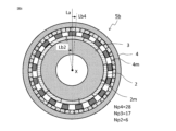
- the magnetic gear 1 includes a multi-pole mechanism 4 in which 4 m of 22 (number of poles Np4) permanent magnets are arranged, and a permanent magnet of 6 (number of poles Np2).
- a section is constituted by a small pole mechanism 2 in which 2 m of magnets are arranged and a pole piece 3 constituted by 14 magnetic pole pieces (number of poles Np3).
- the greatest common divisor of the number of poles Np2 of the small-pole mechanism 2 and the number of poles Np3 of the pole piece 3, and the greatest common divisor of the number of poles Np4 of the multi-pole mechanism 4 and the number of poles Np3 of the pole piece 3 are both 2. Since the greatest common divisor of the number of poles is 2, the least common multiple of the number of poles can be made sufficiently large as in the first embodiment, and the amplitude of the cogging torque can be reduced.
- the spatial symmetry is second-order, so an electromagnetic excitation force having a spatial second-order mode is generated in the circumferential direction.
- the spatial waveform of the second-order component of the electromagnetic excitation force generated in the multipole mechanism 4 is caused by the electromagnetic excitation due to the first section 5a and the second section 5b having a phase difference of 90 degrees in mechanical angle. It can be seen that due to the phase relationship of the second-order vibration force components, they cancel out when added together.
- the amplitude of the spatial second-order component of the electromagnetic excitation force can be made smaller than the amplitude when each section is used alone by adding them together. You can see that it is done.
- the phase difference ⁇ is changed from 0° to 360°, the amplitude of the second-order component of the electromagnetic excitation force space changes as shown in FIG. 16B. If the phase difference ⁇ is in the range of greater than 60° and less than 120°, and in the range of greater than 240° and less than 300°, the amplitude of the electromagnetic excitation force spatial second-order component is made smaller than when each section is used alone. can.
- Embodiment 7 In the magnetic gear according to the seventh embodiment, an example will be described in which the magnetic gear portion is configured with a combination of polarities different from those in the first to fifth embodiments and the sixth embodiment.
- FIG. 17, FIG. 18A, and FIG. 18B are for explaining the configuration and operation of the magnetic gear according to the seventh embodiment, and FIG. 17 shows the configuration of the magnetic gear along the rotation axis including the rotation axis.
- 18A is a sectional view perpendicular to the axis of rotation of the first section corresponding to line FF in FIG. 17, and
- FIG. 18B is a sectional view perpendicular to the axis of rotation of the second section corresponding to line GG in FIG. 17.
- FIG. 17 shows the configuration of the magnetic gear along the rotation axis including the rotation axis.
- 18A is a sectional view perpendicular to the axis of rotation of the first section corresponding to line FF in FIG. 17
- FIG. 18B is a sectional view perpen
- the magnetic gear 1 includes a multi-pole mechanism 4 in which 4 m of 20 permanent magnets (number of poles Np 4) are arranged, and a permanent magnet 4 that has 8 permanent magnets (number of poles Np 2).
- a section is constituted by a small pole mechanism 2 in which 2 m of magnets are arranged and a pole piece 3 constituted by 14 magnetic pole pieces (number of poles Np3).
- the greatest common divisor of the number of poles Np2 of the small-pole mechanism 2 and the number of poles Np3 of the pole piece 3, and the greatest common divisor of the number of poles Np4 of the multi-pole mechanism 4 and the number of poles Np3 of the pole piece 3 are both 2. Since the greatest common divisor of the number of poles is 2, as in the sixth embodiment, the least common multiple of the number of poles can be made sufficiently large, and the amplitude of the cogging torque can be reduced.
- the second section 5b has a shape rotated by 90 degrees in mechanical angle with respect to the first section 5a based on the line segment La. Except for replacing the first section 5a from the arrangement shown in FIG. 2A to the arrangement shown in FIG. 18A, and the second section 5b from the arrangement shown in FIG. 2B to the arrangement shown in FIG. The same is true.
- the phase of the small pole mechanism 2 in the second section matches that of the first section 5a, and as in the first embodiment, there is no need to shift the phase of the small pole mechanism 2 and stack them in the axial direction. Therefore, since it can be shared with the first section 5a, manufacturing equipment for stacking layers with a phase shift is not required, and an increase in manufacturing costs can be suppressed.
- this embodiment has shown an example in which the phase of the small pole mechanism 2 matches between the first section 5a and the second section 5b, the present invention is not limited to this. A similar effect can be obtained by a combination of the number of poles and the phase difference ⁇ such that two or more arrangement patterns in which at least one phase of the small-pole mechanism 2 and the multi-pole mechanism 4 are different are arranged in the axial direction.
- the spatial symmetry is second-order, so that an electromagnetic excitation force having a spatial second-order mode is generated in the circumferential direction.
- the spatial waveform of the second-order component of the electromagnetic excitation force generated in the multipole mechanism 4 is caused by the electromagnetic excitation due to the first section 5a and the second section 5b having a phase difference of 90 degrees in mechanical angle. It can be seen that due to the phase relationship of the second-order vibration force components, when added together, they are canceled out.
- the permanent magnet can be set in the magnetization direction, magnetization orthogonal direction, axial direction, and other A similar effect can be obtained when dividing in the direction.
- the magnetic gear 1 is a radial type having a magnetic gap in a direction perpendicular to the rotation axis is obtained.
- the spatial first-order component of the electromagnetic excitation force can be reduced to the maximum
- the spatial second-order component of the electromagnetic excitation force can be reduced to the maximum.
- one is 1 or 2 even if the other is neither 1 nor 2, it is possible to reduce the spatial first-order component or spatial second-order component of the electromagnetic excitation force.
- the multi-pole mechanism 4 in which the first number of magnetic poles (number of poles Np4) is arranged along the circumferential direction by the permanent magnet 4m, and the first magnetic pole by the permanent magnet 2m
- a small pole mechanism 2 in which magnetic poles with a second number of poles (number of poles Np2) smaller than the number of poles (number of poles Np4) are arranged along the circumferential direction, and a third number of poles (number of poles Np3) made of a soft magnetic material.
Landscapes
- Engineering & Computer Science (AREA)
- Power Engineering (AREA)
- Dynamo-Electric Clutches, Dynamo-Electric Brakes (AREA)
Priority Applications (4)
| Application Number | Priority Date | Filing Date | Title |
|---|---|---|---|
| PCT/JP2022/023312 WO2023238335A1 (ja) | 2022-06-09 | 2022-06-09 | 磁気ギヤ |
| DE112022007346.2T DE112022007346T5 (de) | 2022-06-09 | 2022-06-09 | Magnetgetriebe |
| JP2022557103A JP7179244B1 (ja) | 2022-06-09 | 2022-06-09 | 磁気ギヤ |
| CN202280096517.8A CN119278326A (zh) | 2022-06-09 | 2022-06-09 | 磁性齿轮 |
Applications Claiming Priority (1)
| Application Number | Priority Date | Filing Date | Title |
|---|---|---|---|
| PCT/JP2022/023312 WO2023238335A1 (ja) | 2022-06-09 | 2022-06-09 | 磁気ギヤ |
Publications (1)
| Publication Number | Publication Date |
|---|---|
| WO2023238335A1 true WO2023238335A1 (ja) | 2023-12-14 |
Family
ID=84227613
Family Applications (1)
| Application Number | Title | Priority Date | Filing Date |
|---|---|---|---|
| PCT/JP2022/023312 Ceased WO2023238335A1 (ja) | 2022-06-09 | 2022-06-09 | 磁気ギヤ |
Country Status (4)
| Country | Link |
|---|---|
| JP (1) | JP7179244B1 (https=) |
| CN (1) | CN119278326A (https=) |
| DE (1) | DE112022007346T5 (https=) |
| WO (1) | WO2023238335A1 (https=) |
Families Citing this family (1)
| Publication number | Priority date | Publication date | Assignee | Title |
|---|---|---|---|---|
| JPWO2025074870A1 (https=) * | 2023-10-06 | 2025-04-10 |
Citations (2)
| Publication number | Priority date | Publication date | Assignee | Title |
|---|---|---|---|---|
| WO2015053005A1 (ja) * | 2013-10-09 | 2015-04-16 | 日立金属株式会社 | 磁気歯車装置 |
| WO2017104359A1 (ja) * | 2015-12-17 | 2017-06-22 | 日立金属株式会社 | 磁気変速機 |
-
2022
- 2022-06-09 DE DE112022007346.2T patent/DE112022007346T5/de active Pending
- 2022-06-09 WO PCT/JP2022/023312 patent/WO2023238335A1/ja not_active Ceased
- 2022-06-09 JP JP2022557103A patent/JP7179244B1/ja active Active
- 2022-06-09 CN CN202280096517.8A patent/CN119278326A/zh active Pending
Patent Citations (2)
| Publication number | Priority date | Publication date | Assignee | Title |
|---|---|---|---|---|
| WO2015053005A1 (ja) * | 2013-10-09 | 2015-04-16 | 日立金属株式会社 | 磁気歯車装置 |
| WO2017104359A1 (ja) * | 2015-12-17 | 2017-06-22 | 日立金属株式会社 | 磁気変速機 |
Also Published As
| Publication number | Publication date |
|---|---|
| JP7179244B1 (ja) | 2022-11-28 |
| CN119278326A (zh) | 2025-01-07 |
| DE112022007346T5 (de) | 2025-03-20 |
| JPWO2023238335A1 (https=) | 2023-12-14 |
Similar Documents
| Publication | Publication Date | Title |
|---|---|---|
| JP4270942B2 (ja) | 電動機 | |
| KR100899913B1 (ko) | 모터 | |
| JP5813254B2 (ja) | 永久磁石式回転電機 | |
| CN101779366B (zh) | 轴向间隙型电动机 | |
| CN103051136B (zh) | 马达 | |
| CN112467905B (zh) | 一种游标磁齿轮复合电机 | |
| US20090322174A1 (en) | Permanent-magnet synchronous machine with reduced torque ripple | |
| JP2007028868A (ja) | 回転電機の固定子 | |
| JP2003153508A (ja) | 電動機 | |
| CN101663806A (zh) | 轴向间隙型电机 | |
| US7420306B2 (en) | Brushless DC motor | |
| US20070170802A1 (en) | Permanent-magnet excited synchronous motor | |
| JP2007074870A (ja) | 永久磁石埋込型ロータおよび永久磁石埋込型モータ | |
| JP4463947B2 (ja) | ブラシレスdcモータの構造 | |
| JP7686150B2 (ja) | 磁気ギア装置 | |
| JP7179244B1 (ja) | 磁気ギヤ | |
| JP4605480B2 (ja) | アキシャルギャップ型モータ | |
| US20080265705A1 (en) | Rotary Machine and Electromagnetic Machine | |
| JP7595496B2 (ja) | 磁気ギアード回転機械、及び発電システム | |
| JP7258100B1 (ja) | 回転電機 | |
| JP2013132154A (ja) | 回転電機および回転電機のロータ | |
| JP5855903B2 (ja) | ロータ及びモータ | |
| CN112448503A (zh) | 转子、马达以及驱动装置 | |
| JP2009284716A (ja) | アウタロータ型ブラシレスモータ | |
| JP5352442B2 (ja) | 永久磁石モータ |
Legal Events
| Date | Code | Title | Description |
|---|---|---|---|
| ENP | Entry into the national phase |
Ref document number: 2022557103 Country of ref document: JP Kind code of ref document: A |
|
| 121 | Ep: the epo has been informed by wipo that ep was designated in this application |
Ref document number: 22945837 Country of ref document: EP Kind code of ref document: A1 |
|
| WWE | Wipo information: entry into national phase |
Ref document number: 202280096517.8 Country of ref document: CN |
|
| WWP | Wipo information: published in national office |
Ref document number: 202280096517.8 Country of ref document: CN |
|
| WWE | Wipo information: entry into national phase |
Ref document number: 112022007346 Country of ref document: DE |
|
| WWP | Wipo information: published in national office |
Ref document number: 112022007346 Country of ref document: DE |
|
| 122 | Ep: pct application non-entry in european phase |
Ref document number: 22945837 Country of ref document: EP Kind code of ref document: A1 |