WO2023234342A1 - 固体電解コンデンサ - Google Patents
固体電解コンデンサ Download PDFInfo
- Publication number
- WO2023234342A1 WO2023234342A1 PCT/JP2023/020255 JP2023020255W WO2023234342A1 WO 2023234342 A1 WO2023234342 A1 WO 2023234342A1 JP 2023020255 W JP2023020255 W JP 2023020255W WO 2023234342 A1 WO2023234342 A1 WO 2023234342A1
- Authority
- WO
- WIPO (PCT)
- Prior art keywords
- resin
- solid electrolytic
- electrolytic capacitor
- exterior body
- glass transition
- Prior art date
- Legal status (The legal status is an assumption and is not a legal conclusion. Google has not performed a legal analysis and makes no representation as to the accuracy of the status listed.)
- Ceased
Links
Images

Classifications
-
- H—ELECTRICITY
- H01—ELECTRIC ELEMENTS
- H01G—CAPACITORS; CAPACITORS, RECTIFIERS, DETECTORS, SWITCHING DEVICES, LIGHT-SENSITIVE OR TEMPERATURE-SENSITIVE DEVICES OF THE ELECTROLYTIC TYPE
- H01G9/00—Electrolytic capacitors, rectifiers, detectors, switching devices, light-sensitive or temperature-sensitive devices; Processes of their manufacture
- H01G9/15—Solid electrolytic capacitors
-
- H—ELECTRICITY
- H01—ELECTRIC ELEMENTS
- H01G—CAPACITORS; CAPACITORS, RECTIFIERS, DETECTORS, SWITCHING DEVICES, LIGHT-SENSITIVE OR TEMPERATURE-SENSITIVE DEVICES OF THE ELECTROLYTIC TYPE
- H01G9/00—Electrolytic capacitors, rectifiers, detectors, switching devices, light-sensitive or temperature-sensitive devices; Processes of their manufacture
- H01G9/004—Details
- H01G9/008—Terminals
- H01G9/012—Terminals specially adapted for solid capacitors
-
- H—ELECTRICITY
- H01—ELECTRIC ELEMENTS
- H01G—CAPACITORS; CAPACITORS, RECTIFIERS, DETECTORS, SWITCHING DEVICES, LIGHT-SENSITIVE OR TEMPERATURE-SENSITIVE DEVICES OF THE ELECTROLYTIC TYPE
- H01G9/00—Electrolytic capacitors, rectifiers, detectors, switching devices, light-sensitive or temperature-sensitive devices; Processes of their manufacture
- H01G9/004—Details
- H01G9/022—Electrolytes; Absorbents
- H01G9/025—Solid electrolytes
- H01G9/028—Organic semiconducting electrolytes, e.g. TCNQ
-
- H—ELECTRICITY
- H01—ELECTRIC ELEMENTS
- H01G—CAPACITORS; CAPACITORS, RECTIFIERS, DETECTORS, SWITCHING DEVICES, LIGHT-SENSITIVE OR TEMPERATURE-SENSITIVE DEVICES OF THE ELECTROLYTIC TYPE
- H01G9/00—Electrolytic capacitors, rectifiers, detectors, switching devices, light-sensitive or temperature-sensitive devices; Processes of their manufacture
- H01G9/004—Details
- H01G9/08—Housing; Encapsulation
-
- H—ELECTRICITY
- H01—ELECTRIC ELEMENTS
- H01G—CAPACITORS; CAPACITORS, RECTIFIERS, DETECTORS, SWITCHING DEVICES, LIGHT-SENSITIVE OR TEMPERATURE-SENSITIVE DEVICES OF THE ELECTROLYTIC TYPE
- H01G9/00—Electrolytic capacitors, rectifiers, detectors, switching devices, light-sensitive or temperature-sensitive devices; Processes of their manufacture
- H01G9/004—Details
- H01G9/08—Housing; Encapsulation
- H01G9/10—Sealing, e.g. of lead-in wires
Definitions
- the present disclosure relates to solid electrolytic capacitors.
- Solid electrolytic capacitors have low equivalent series resistance (ESR) and excellent frequency characteristics, so they are installed in various electronic devices.
- a solid electrolytic capacitor includes a capacitor element, a lead terminal electrically connected to the capacitor element, and an exterior body that seals a portion of the lead terminal and the capacitor element.
- solid electrolytic capacitors exhibit low ESR and excellent frequency characteristics.
- Solid electrolytic capacitors are generally soldered to a substrate through a reflow process that involves exposure to high temperatures. At that time, cracks may be formed in the exterior body due to thermal stress, and the sealing performance of the exterior body may be reduced. When the sealing performance deteriorates, the conductive polymer contained in the solid electrolyte layer is oxidized and deteriorated by moisture and oxygen that have entered the solid electrolytic capacitor. As a result, the conductivity of the solid electrolyte layer decreases, causing a decrease in capacitance and an increase in ESR of the solid electrolytic capacitor. Therefore, various solid electrolytic capacitors have been proposed with the aim of improving the sealing performance of the exterior body.
- Patent Document 1 describes "a solid electrolytic capacitor including a sintered porous anode body, a dielectric body disposed on the anode body, and a solid electrolyte disposed on the dielectric body. a capacitor element; an anode lead extending from the surface of the capacitor element; an anode termination electrically connected to the anode lead; and a cathode termination electrically connected to the solid electrolyte; A casing material enclosing an anode lead, the casing material being formed from a curable resinous matrix having a coefficient of thermal expansion of less than about 42 ppm/° C. at temperatures above the glass transition temperature of the resinous matrix.
- said casing material said capacitor exhibiting an initial equivalent series resistance of less than about 200 milliohms as determined at an operating frequency of 100 kHz and a temperature of 23°C;
- the solid electrolytic capacitor wherein the ratio of equivalent series resistance of the capacitor after exposure for a period of time is less than or equal to about 2.0.
- an object of the present disclosure is to provide a solid electrolytic capacitor with excellent heat resistance and whose outer casing has high sealability even at high temperatures.
- the present disclosure relates to solid electrolytic capacitors.
- the solid electrolytic capacitor is a solid electrolytic capacitor that includes a capacitor element, a lead terminal electrically connected to the capacitor element, and an exterior body that seals a part of the lead terminal and the capacitor element.
- the exterior body includes a resin part containing a resin, and the temperature at which the loss modulus of the resin part changes from increasing to decreasing as measured by nanoscale dynamic viscoelasticity measurement using the nanoindentation method.
- the glass transition point Tg of the resin is 140° C. or lower, and the resin portion is measured by a nanoindentation method in a temperature range of not less than the glass transition point Tg and not more than 260° C.
- the hardness is 0.08 GPa or less.
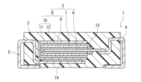
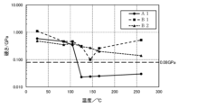
- FIG. 1 is a vertical cross-sectional view schematically showing a solid electrolytic capacitor according to an embodiment of the present disclosure. It is a graph showing the relationship between the temperature and loss modulus of resin contained in the exterior body of a solid electrolytic capacitor. It is a graph showing the relationship between the temperature and hardness of a resin part included in the exterior body of a solid electrolytic capacitor.
- the solid electrolytic capacitor according to this embodiment includes a capacitor element, a lead terminal electrically connected to the capacitor element, and an exterior body that seals a part of the lead terminal and the capacitor element.
- the exterior body includes a resin portion containing resin.
- the resin may be hereinafter referred to as "resin (R)".
- the hardness of the resin part measured by the nanoindentation method (in other words, the hardness found when the resin part is measured by the nanoindentation method) in the temperature range from the glass transition point Tg to 260°C ) is 0.08 GPa or less.
- the hardness of the resin portion measured by a nanoindentation method may be 0.08 GPa or less in a temperature range of 140° C. or higher and 260° C. or lower.
- the capacitor element can be improved by controlling the glass transition point Tg of the resin (R) contained in the exterior body and the hardness of the resin part containing the resin (R) in the exterior body.
- Tg glass transition point
- the resin (R) included in the exterior body of the solid electrolytic capacitor according to the present embodiment has a glass transition point Tg of 140° C. or less, and becomes a rubber state in a temperature range from the glass transition point Tg to 260° C. Furthermore, in this temperature range, the resin part containing the resin (R) has a low hardness of 0.08 GPa or less as measured by a nanoindentation method.
- Solid electrolytic capacitors are generally exposed to high temperatures (for example, temperatures in the range of 180° C. to 260° C.) during a reflow process and the like. Additionally, solid electrolytic capacitors may be used at high temperatures. When a solid electrolytic capacitor is exposed to high temperatures, each member of the solid electrolytic capacitor thermally expands. However, since each member has a different coefficient of thermal expansion, thermal stress occurs inside the solid electrolytic capacitor. As a result, when a conventional solid electrolytic capacitor is exposed to high temperatures, cracks and peeling tend to occur at the interface between the exterior body and the capacitor element and at the interface between the exterior body and the lead terminal.
- the solid electrolytic capacitor according to this embodiment When the solid electrolytic capacitor according to this embodiment is exposed to a temperature equal to or higher than the glass transition point Tg, the resin (R) contained in the exterior body becomes a rubber state, and the hardness of the resin part containing the resin (R) decreases. It is sufficiently low at 0.08 GPa or less. Therefore, the exterior body can disperse and relieve stress applied to the exterior body from the capacitor element and the lead terminal throughout the exterior body. As a result, it is possible to suppress the occurrence of cracks inside the exterior body, and it is also possible to suppress cracks and peeling that occur at the interface between the exterior body, the capacitor element, and the lead terminal. As described above, the solid electrolytic capacitor according to the present embodiment has a high sealability of the exterior body even at high temperatures, and has excellent heat resistance.
- the resin part contains resin (R).
- the resin part may be composed only of resin (R) or may contain components other than resin (R). Examples of components other than the resin (R) include a curing aid (hardening accelerator), a low stress agent (flexibility agent), a mold release agent, a coupling agent, a coloring agent, an ion trapping agent, and the like.
- the proportion of the resin (R) in the resin part may be in the range of 70 to 100% by mass, 80 to 100% by mass, or 90 to 100% by mass.
- the resin (R) contained in the resin part may be composed of only one type of resin, or may include multiple types of resin.
- the resin (R) contains multiple types of resins, it is sufficient that 50% by mass or more of the resins constituting the resin (R) satisfy the above condition (glass transition point Tg).
- the above condition glass transition point Tg
- all resins contained in the resin (R) satisfy the above condition (glass transition point Tg).
- the glass transition point Tg of the resin (R) can be determined by nanoscale dynamic viscoelasticity measurement (nanoDMA) using the nanoindentation method. For example, it is determined by cutting out a part of the exterior body and performing the measurement on the resin part of the cross section. Details of an example of the measurement method will be explained in Examples.
- the resin part contains a filler
- the measurement is carried out by bringing a triangular pyramid indenter into contact with the part where the filler is not present.
- the loss modulus of the resin (R) is measured at each temperature while increasing the temperature, a behavior in which the loss modulus increases and then decreases is observed. At this time, the temperature at which the loss modulus changes from increasing to decreasing is defined as the glass transition point Tg.
- the loss modulus of the resin part is measured while the resin part is heated by nanoscale dynamic viscoelasticity measurement using the nanoindentation method
- the temperature at which the loss modulus changes from increasing to decreasing is the temperature of the resin.
- the glass transition point of (R) is Tg.
- the loss modulus can be determined, for example, by performing dynamic viscoelasticity measurement at five arbitrary points on the resin part and finding the average value of the measured values.
- the glass transition point Tg of the resin (R) may be 125°C or lower.
- the exterior body can relax stress in a wide temperature range and maintain high sealing performance.
- the glass transition point Tg depends on the type, structure, crosslinking density, etc. of the resin. For example, by lowering the crosslinking density of the resin, the glass transition point Tg tends to decrease.
- the hardness of the resin part containing the resin (R) is also measured using the nanoindentation method in the same way as the glass transition point of the resin (R). For example, it can be determined by cutting out a part of the exterior body and continuously measuring the stiffness of the resin section of the cross section. Details of an example of the measurement method will be explained in Examples. When the resin part contains a filler, the measurement is carried out by bringing a triangular pyramid indenter into contact with the part where the filler is not present. Hardness can be determined, for example, by measuring arbitrary five points on the resin part and finding the average value of the measured values.
- the hardness of the resin part in the temperature range from the glass transition point Tg to 260°C is 0. It may be .05 GPa or less, or it may be 0.03 GPa or less. In another embodiment, the hardness of the resin portion in a temperature range of 140° C. or higher and 260° C. or lower may be 0.05 GPa or less, or 0.03 GPa or less.
- the hardness of the resin portion may be changed by changing the type, structure, crosslinking density, etc. of the resin (R). For example, when the distance between crosslinking points of the resin (R) contained in the resin part is increased, the hardness tends to decrease.
- the resin (R) is not particularly limited as long as it has the above properties.
- it may be a thermosetting resin or a thermoplastic resin.
- thermosetting resin examples include epoxy resin, phenol resin, urea resin, polyimide resin, polyamideimide resin, polyurethane resin, diallyl phthalate resin, and unsaturated polyester resin.
- resin (R) one type of these resins may be used alone, or two or more types may be used in combination.
- thermoplastic resin for example, polyphenylene sulfide (PPS), polybutylene terephthalate (PBT), etc. can be used.
- resin (R) one type of these resins may be used alone, or two or more types may be used in combination.
- the resin (R) may contain or be an epoxy resin.
- Epoxy resin has excellent electrical insulation, water resistance, chemical resistance, etc., and furthermore, the glass transition point Tg of the resin (R) and the hardness of the resin part can be easily controlled.
- Epoxy resins are generally obtained by a crosslinking reaction between a base material, which is a monomer or polymer (prepolymer) having an epoxy group, and a curing agent.
- a prepolymer such as a polyaromatic ring type epoxy resin, a biphenyl type epoxy resin, a cresol novolac type epoxy resin, a dicyclopentadiene type epoxy resin, etc. may be used.
- the polyaromatic epoxy resin is an epoxy resin that has a plurality of polyaromatic rings in its main skeleton.
- Polyaromatic epoxy resins have low viscosity at high temperatures. Therefore, for example, when the lead terminal is subjected to blasting, the adhesive strength between the lead terminal and the exterior body containing the polyaromatic ring type epoxy resin is physically increased due to the anchor effect.
- the glass transition point Tg of the resin (R) depends on the crosslinking density and structure of the epoxy resin. Therefore, the glass transition point Tg can be controlled by, for example, the types of the main agent and the curing agent, the blending ratio of the main agent and the curing agent, the molecular weight of the main agent, and the like. For example, when the concentration of functional groups (epoxy groups) in the base resin is low, or when the epoxy equivalent of the base resin is low, the crosslinking density of the epoxy resin tends to be low, and the glass transition point Tg tends to be low.
- the main ingredients have the same skeleton structure, the fewer the number of nuclei, the fewer the number of functional groups, the lower the crosslinking density of the epoxy resin, and the lower the glass transition point Tg.
- the base resin has a similar epoxy equivalent weight, the fewer the number of nuclei, the fewer the number of functional groups, the lower the crosslinking density of the epoxy resin, and the lower the glass transition point Tg.
- the glass transition point Tg tends to be high.
- the epoxy resin has a bulky substituent, the glass transition point Tg also tends to be high.
- the curing agent is not particularly limited and is appropriately selected depending on the type of the main ingredient.
- curing agents include polyfunctional or polyaromatic novolac curing agents such as phenol novolac, acid anhydride curing agents such as tetrahydrophthalic anhydride and hexahydrophthalic anhydride, and amines such as ethylenediamine and aromatic amines. Examples include hardening agents.
- a polymerization initiator, a catalyst, etc. may be used in addition to the base resin and the curing agent.
- the polymerization initiator, catalyst, etc. may also be selected appropriately depending on the type of the main ingredient.
- the catalyst include phosphorus compounds such as triphenylphosphine and its modified products, amines, and imidazoles.
- the exterior body may further include a filler dispersed in the resin portion.
- the exterior body may be comprised of a resin part and a filler dispersed in the resin part.
- the filler is dispersed in the resin part containing resin (R).
- the filler is not particularly limited, and any known filler can be used.
- insulating fillers such as insulating particles and insulating fibers are used.
- the insulating material constituting the insulating filler include insulating compounds such as silica, alumina, aluminum nitride, and boron nitride, glass, and mineral materials (talc, mica, clay, etc.).
- the number of fillers contained in the exterior body may be one, or two or more.
- the content of filler in the exterior body is preferably in the range of 75% by mass to 90% by mass. Further, the content may be 78% by mass or more and 86% by mass or less.
- the maximum particle size of the filler may be 100 ⁇ m or less (for example, 55 ⁇ m or less). By setting the maximum particle size to 55 ⁇ m or less, stress can be easily relaxed as described above.
- the maximum particle size refers to the particle size of the largest particle among the filler particles contained in the exterior body.
- the maximum particle size is determined by photographing a cross section of the outer package, arbitrarily selecting 100 particles, and measuring the cross-sectional area of the particles. Among the equivalent circles having the same area as the cross-sectional area of each particle, the diameter of the largest equivalent circle is the maximum particle size.
- the solid electrolytic capacitor according to this embodiment has high heat resistance, and the sealing performance of the exterior body is maintained even at high temperatures. Therefore, moisture and oxygen are prevented from entering the solid electrolytic capacitor, and deterioration of the conductive polymer in the solid electrolyte contained in the capacitor element is less likely to occur. Therefore, even when exposed to high temperatures, the capacitance and ESR of the solid electrolytic capacitor are maintained.
- Capacitance change rate (%) 100 x (C1-C0)/C0 (In the formula, C0 is the initial capacitance, and C1 is the capacitance after heating at 125°C for 7000 hours.)
- the average value of the capacitance change rate expressed by may be ⁇ 5.0% or more.
- the average value may be -3.0% or more, or -1.0% or more.
- the average value is an average value of the capacitance change rates of at least 60 (for example, 100) solid electrolytic capacitors.
- Capacitance can be measured using, for example, an LCR meter.
- the capacitance change rate of one solid electrolytic capacitor is preferably -5.0% or more, more preferably -3.0% or more.
- the solid electrolytic capacitor according to the present embodiment includes a capacitor element, a lead terminal, and an exterior body, and includes other components as necessary.
- An example of the structure of a solid electrolytic capacitor will be described below.
- the configuration of the solid electrolytic capacitor is not limited to the following example.
- a known configuration may be applied to the configuration other than the configuration characteristic of the solid electrolytic capacitor according to this embodiment.
- the solid electrolytic capacitor may include a case made of metal or the like in addition to the above-described exterior body.
- Solid electrolytic capacitors have one or more capacitor elements. Note that the number of capacitor elements included in a solid electrolytic capacitor is determined depending on the application. When including two or more capacitor elements, the capacitor elements are typically stacked. In this case, an anode lead terminal is connected to an anode stacked part in which a plurality of anode parts are stacked, and a cathode lead terminal is connected to a cathode stacked part in which a plurality of cathode parts are stacked.
- the anode body can include a valve metal, an alloy containing a valve metal, a compound containing a valve metal, and the like. These materials may be used alone or in combination of two or more.
- the valve metal for example, aluminum, tantalum, niobium, and titanium are preferably used.
- the surface of the anode body may have a porous structure.
- a porous structure can be obtained by roughening the surface of a base material (such as a foil-like or plate-like base material) containing a valve metal by etching or the like.
- the anode body may be a molded body of particles containing a valve metal or a sintered body thereof.
- the anode portion may include an anode wire partially embedded in the sintered body. In that case, one end of the anode lead terminal is connected to the anode wire.
- the dielectric layer is an insulating layer formed to cover at least a portion of the surface of the anode body. Although not particularly limited as long as it functions as a dielectric layer, it is formed, for example, by anodic oxidation of the valve metal on the surface of the anode body by chemical conversion treatment or the like.
- the dielectric layer includes an oxide of a valve metal.
- the dielectric layer contains Ta 2 O 5 when tantalum is used as the valve metal, and the dielectric layer contains Al 2 O 3 when aluminum is used as the valve metal.
- the solid electrolyte layer is formed to cover at least a portion of the dielectric layer.
- the solid electrolyte layer contains a conductive polymer.
- a conductive polymer polypyrrole, polythiophene, polyfuran, polyaniline, polyacetylene, polyphenylene, polyphenylene vinylene, polyacene, polythiophene vinylene, and derivatives thereof can be used. Examples of the derivative include poly(3,4-ethylenedioxythiophene).
- a dopant may be added to the conductive polymer.
- the dopant can be selected depending on the conductive polymer, and known dopants may be used. Examples of dopants include naphthalenesulfonic acid, p-toluenesulfonic acid, polystyrenesulfonic acid, and salts thereof.
- a solid electrolyte layer containing a conductive polymer may be formed by polymerizing a monomer as a raw material on a dielectric layer.
- a solid electrolyte layer may be formed by disposing a liquid containing a conductive polymer on a dielectric layer and then drying the liquid.
- the cathode extraction layer only needs to include a first layer that covers at least a portion of the solid electrolyte layer, and may include a first layer and a second layer that covers the first layer. Both the first layer and the second layer are conductive layers.
- the first layer is formed of, for example, a layer containing conductive particles, metal foil, or the like. Examples of the conductive particles include conductive carbon and metal powder.
- the second layer is formed of, for example, a layer containing metal powder or metal foil.
- the layer containing metal powder is formed using, for example, a composition (metal paste) containing metal powder such as silver particles and a resin (binder resin).
- the adhesive layer connects the cathode lead terminal and the cathode section.
- the adhesive layer includes conductive particles. Examples of the conductive particles include metal particles (eg, silver particles).
- the adhesive layer is formed using a metal paste containing metal particles and resin.
- the lead terminals include an anode lead terminal and a cathode lead terminal. One end side of the anode lead terminal and the cathode lead terminal is sealed together with the capacitor element by an exterior body. One end of the anode lead terminal is electrically connected to the anode of the capacitor element, and the other end is exposed to the outside of the exterior body. One end of the cathode lead terminal is electrically connected to the cathode of the capacitor element, and the other end is exposed to the outside of the exterior body.
- the anode lead terminal and cathode lead terminal exposed from the exterior body are used for solder connection to a board on which the solid electrolytic capacitor is mounted.
- lead terminals generally used in solid electrolytic capacitors can be used without particular restriction.
- the material include metals such as copper or alloys thereof.
- the surfaces of the anode lead terminal and the cathode lead terminal may be subjected to blasting treatment. Blasting improves the adhesion strength between the lead terminal and the exterior body, making it difficult for cracks and peeling to occur at the interface.
- the exterior body seals the capacitor element and a portion of the anode lead terminal and the cathode lead terminal.
- the exterior body described above is used as the exterior body.
- the exterior body can be formed using molding techniques such as injection molding, insert molding, and compression molding.
- An uncured resin mixture is used for molding.
- a resin mixture containing a base material (monomer, prepolymer, etc.) that is a raw material for the resin (R), a curing agent, a filler, etc. is used.
- the molding is performed, for example, by using a predetermined mold and filling a predetermined location with a resin mixture so as to cover the capacitor element and one end of the lead terminal.
- the resin mixture is cured by molding, and an exterior body including a resin part containing resin (R) is formed.
- a capacitor element includes a step of forming a dielectric layer to cover at least a portion of an anode body, a step of forming a solid electrolyte layer to cover at least a portion of the dielectric layer, and a step of forming a solid electrolyte layer to cover at least a portion of the dielectric layer. It is manufactured by a manufacturing method that includes a step of forming a cathode extraction layer on a portion.
- the step of forming the cathode extraction layer includes, for example, a step of forming a carbon layer and a step of forming a silver paste layer on at least a portion of the carbon layer.
- the method may include a step of preparing an anode body prior to the step of forming the dielectric layer.
- a solid electrolytic capacitor is manufactured by a manufacturing method that includes, for example, a step of electrically connecting a lead terminal to a capacitor element, and a step of covering a portion of the capacitor element and the lead terminal with an exterior body (sealing step).
- the solid electrolytic capacitor may be of a wound type, a chip type, or a laminated type.
- FIG. 1 The configuration of an example of the solid electrolytic capacitor according to this embodiment will be explained using FIG. 1.
- the above-mentioned components can be applied to the example components described below. Further, the constituent elements of the example described below can be changed based on the above description.
- FIG. 1 is a cross-sectional view schematically showing the structure of an example solid electrolytic capacitor 1 according to the present embodiment.
- Solid electrolytic capacitor 1 includes a capacitor element 2, lead terminals (anode lead terminal 4 and cathode lead terminal 5), and an exterior body 3 that seals a portion of the lead terminal and capacitor element 2. A portion of the anode lead terminal 4 and a portion of the cathode lead terminal 5 are exposed from the exterior body 3.
- the exterior body described above is used for the exterior body 3.
- the capacitor element 2 includes an anode body 6 constituting an anode part, a dielectric layer 7 covering the anode body 6, and a cathode part 8 covering the dielectric layer 7.
- the anode body 6 includes a region facing the cathode section 8 and a region not facing the cathode section 8.
- An insulating separation layer 13 is formed in a region adjacent to the cathode part 8 of the anode body 6 that does not face the cathode part 8 so as to cover the surface of the anode body 6 in a band-like manner. Contact with the body 6 is regulated.
- the other part of the region of the anode body 6 that does not face the cathode section 8 is electrically connected to the anode lead terminal 4 by welding.
- the cathode lead terminal 5 is electrically connected to the cathode section 8 via an adhesive layer 14 formed of a conductive adhesive.
- the cathode section 8 includes a solid electrolyte layer 9 covering the dielectric layer 7 and a cathode extraction layer 10 covering the solid electrolyte layer 9.
- the cathode extraction layer 10 has a carbon layer 11 and a silver paste layer 12.
- a solid electrolytic capacitor including a capacitor element, a lead terminal electrically connected to the capacitor element, and an exterior body that seals a part of the lead terminal and the capacitor element,
- the exterior body includes a resin part containing resin,
- the glass transition point Tg of the resin the glass transition point Tg is 140°C or less
- Capacitance change rate (%) 100 x (C1-C0)/C0 (In the formula, C0 is the initial capacitance, and C1 is the capacitance after heating at 125°C for 7000 hours.)
- Solid electrolytic capacitors A1, B1, and B2 were produced in the following manner.
- a silver paste containing silver particles and a binder resin epoxy resin
- the binder resin was cured by heating at 150° C. for 30 minutes to form a silver paste layer.
- a cathode extraction layer composed of a carbon layer and a silver paste layer was formed, and a cathode section including a solid electrolyte layer and a cathode extraction layer was formed.
- a capacitor element was produced through the steps (1-a) to (1-d).
- the following resin mixtures 1 to 3 were used to form an exterior body around the capacitor element and lead terminals by molding. At this time, the other end of the anode lead terminal and the other end of the cathode lead terminal were exposed from the exterior body. In this way, solid electrolytic capacitors A1, B1, and B2 were completed.
- the following resin mixture 1 was used for the solid electrolytic capacitor A1
- the following resin mixture 2 was used for the solid electrolytic capacitor B1
- the following resin mixture 3 was used for the solid electrolytic capacitor B2.
- the resin part of the exterior body formed of the resin mixture 1 contains a polyaromatic ring type epoxy resin as the resin (R). Note that filler is dispersed in the following resin mixture.
- Resin mixture 1 The glass transition point Tg measured by nanoDMA in the resin part formed by curing is around 125°C, and the hardness of the resin part is 0.08 or less in a temperature range higher than the glass transition point Tg. resin mixture.
- Resin mixture 2 The glass transition point Tg measured by nanoDMA in the resin part formed by curing is around 145°C, and the hardness of the resin part is less than 0.08 in a temperature range higher than the glass transition point Tg. Large resin mixture.
- Resin mixture 3 The glass transition point Tg measured by nanoDMA in the resin part formed by curing is around 165°C, and the hardness of the resin part is 0.08 or higher in a temperature range higher than the glass transition point Tg. Large resin mixture.
- Nanoscale dynamic viscoelasticity measurements were performed using the following method.
- a diamond triangular pyramid indenter (Berkovich indenter) was brought into contact with a portion (resin portion) that did not include filler in the cross section of the sample, and the indenter was caused to vibrate minutely.
- the response amplitude and phase difference to the vibrations were obtained as a function of time, and the stiffness and sample damping were calculated.
- the loss modulus was calculated using the calculated sample damping results. The loss modulus at each temperature was determined by calculating the average value of the measured values at five points. The results are shown in Figure 2.
- the glass transition point Tg The glass transition points Tg of the resins contained in the exterior bodies of solid electrolytic capacitors A1, B1, and B2 were 125°C, about 145°C (temperature in the range of 145°C to 165°C), and 165°C, respectively.
- the hardness of the resin part included in the solid electrolytic capacitor A1 was 0.08 GPa or less in a temperature range from the glass transition point Tg (125°C) of the resin to 260°C.
- the hardness of the resin parts included in solid electrolytic capacitors B1 and B2 is 260°C above the glass transition point Tg of the resin (resin of solid electrolytic capacitor B1: approximately 145°C, resin of solid electrolytic capacitor B2: 165°C). In the following temperature ranges, the values were higher than 0.08 GPa.
- solid electrolytic capacitor A1 is the solid electrolytic capacitor according to the present embodiment.
- Solid electrolytic capacitors B1 and B2 are solid electrolytic capacitors of comparative examples.
- each solid electrolytic capacitor In an environment of 20° C., the capacitance ( ⁇ F) of each solid electrolytic capacitor at a frequency of 120 Hz was measured as the initial capacitance C0 ( ⁇ F) using an LCR meter for four-terminal measurement. Thereafter, each solid electrolytic capacitor was heated under the same temperature conditions as the reflow treatment according to IPC/JEDEC J-STD-020D (heating at a maximum temperature of 260° C. and above 255° C. for 30 seconds). Next, a high temperature storage test was conducted in which the solid electrolytic capacitor was left in an environment of 125° C. for 7000 hours.
- Capacitance change rate (%) 100 x (C1-C0)/C0
- the average value was determined by arithmetic averaging the capacitance change rates of 100 solid electrolytic capacitors A1. Similarly, the average value of the capacitance change rate of 60 solid electrolytic capacitors B1 and the average value of the capacitance change rate of 60 solid electrolytic capacitors B2 were determined. The evaluation results are shown in Table 1. As the deterioration of the solid electrolytic capacitor increases, the capacitance change rate becomes negative. A capacitance change rate close to 0 (or positively large) indicates that the solid electrolytic capacitor has little deterioration.
- the average value of the capacitance change rate of solid electrolytic capacitor A1 after the high temperature storage test is -5% or more (i.e. -5.0 ⁇ 100 ⁇ (C1-C0)/C0).
- the solid electrolytic capacitor deteriorates less (that is, the value of the capacitance change rate changes more to the positive side).
- the average value of the capacitance change rate after the high temperature storage test of solid electrolytic capacitors B1 and B2 was lower than -5%. This means that solid electrolytic capacitor A1, unlike solid electrolytic capacitors B1 and B2, exhibits less decrease in capacitance even when exposed to high temperatures for a long time.
- ESR change rate Changes in ESR (equivalent series resistance) of solid electrolytic capacitors A1, B1, and B2 at 125° C. were measured using the following procedure.
- the ESR change rates of 100 solid electrolytic capacitors A1 were arithmetic averaged to obtain an average value.
- the average value of the ESR change rate of 60 solid electrolytic capacitors B1 and the average value of the ESR change rate of 60 solid electrolytic capacitors B2 were determined. The results are shown in Table 2. As the deterioration of the solid electrolytic capacitor increases, the ESR change rate increases. The smaller the ESR change rate, the less deterioration of the solid electrolytic capacitor.
- the ESR change rate of solid electrolytic capacitor A1 was a significantly lower value than the ESR change rate of solid electrolytic capacitors B1 and B2.
- each solid electrolytic capacitor was placed inside a small capsule, and the minute pressure drop caused by the internal pressure inside the small capsule leaking into the exterior body was measured. Then, a capacitor whose pressure change at this time was larger than a predetermined value was determined to have poor airtightness, and the percentage of poor airtightness (%) was determined.
- the solid electrolytic capacitor A1 is the solid electrolytic capacitor according to the present embodiment. It was confirmed that in the solid electrolytic capacitor A1, a decrease in capacitance and an increase in ESR were suppressed even when exposed to high temperatures.
- the resin contained in the exterior body of the solid electrolytic capacitor A1 is in a rubber state at 125° C. when the high temperature storage test was conducted, and the hardness of the resin part containing the resin is as low as 0.08 GPa or less. Therefore, it is thought that the stress applied to the exterior body from the capacitor element and the lead terminals can be alleviated in the entire exterior body, suppressing the occurrence of cracks and peeling, and improving airtightness. As a result, it is presumed that the exterior body was able to maintain high sealing performance even under high temperatures.
- the solid electrolytic capacitor of the present disclosure has a high sealability of the exterior body even at high temperatures, and can suppress a decrease in capacitance and an increase in ESR. Therefore, it can be used in various applications that require high reliability.
- Electrolytic capacitor Capacitor element 3 Exterior body 4 Anode lead terminal 5 Cathode lead terminal 6 Anode body 7 Dielectric layer 8 Cathode part 9 Solid electrolyte layer 10 Cathode extraction layer 11 Carbon layer 12 Silver paste layer 13 Separation layer 14 Adhesive layer
Landscapes
- Engineering & Computer Science (AREA)
- Power Engineering (AREA)
- Microelectronics & Electronic Packaging (AREA)
- Chemical & Material Sciences (AREA)
- Chemical Kinetics & Catalysis (AREA)
- Electrochemistry (AREA)
- Compositions Of Macromolecular Compounds (AREA)
- Fixed Capacitors And Capacitor Manufacturing Machines (AREA)
Priority Applications (3)
| Application Number | Priority Date | Filing Date | Title |
|---|---|---|---|
| JP2024524904A JP7796341B2 (ja) | 2022-05-31 | 2023-05-31 | 固体電解コンデンサ |
| CN202380041614.1A CN119234286A (zh) | 2022-05-31 | 2023-05-31 | 固体电解电容器 |
| US18/962,950 US20250087424A1 (en) | 2022-05-31 | 2024-11-27 | Solid electrolytic capacitor |
Applications Claiming Priority (2)
| Application Number | Priority Date | Filing Date | Title |
|---|---|---|---|
| JP2022088857 | 2022-05-31 | ||
| JP2022-088857 | 2022-05-31 |
Related Child Applications (1)
| Application Number | Title | Priority Date | Filing Date |
|---|---|---|---|
| US18/962,950 Continuation US20250087424A1 (en) | 2022-05-31 | 2024-11-27 | Solid electrolytic capacitor |
Publications (1)
| Publication Number | Publication Date |
|---|---|
| WO2023234342A1 true WO2023234342A1 (ja) | 2023-12-07 |
Family
ID=89024888
Family Applications (1)
| Application Number | Title | Priority Date | Filing Date |
|---|---|---|---|
| PCT/JP2023/020255 Ceased WO2023234342A1 (ja) | 2022-05-31 | 2023-05-31 | 固体電解コンデンサ |
Country Status (4)
| Country | Link |
|---|---|
| US (1) | US20250087424A1 (https=) |
| JP (1) | JP7796341B2 (https=) |
| CN (1) | CN119234286A (https=) |
| WO (1) | WO2023234342A1 (https=) |
Citations (3)
| Publication number | Priority date | Publication date | Assignee | Title |
|---|---|---|---|---|
| JPH0288227U (https=) * | 1988-01-26 | 1990-07-12 | ||
| JP2010087308A (ja) * | 2008-09-30 | 2010-04-15 | Sanyo Electric Co Ltd | 固体電解コンデンサ |
| WO2022059459A1 (ja) * | 2020-09-17 | 2022-03-24 | パナソニックIpマネジメント株式会社 | 固体電解コンデンサ |
Family Cites Families (2)
| Publication number | Priority date | Publication date | Assignee | Title |
|---|---|---|---|---|
| JPH05136009A (ja) * | 1991-11-11 | 1993-06-01 | Elna Co Ltd | チツプ型固体電解コンデンサおよびその製造方法 |
| JP5330191B2 (ja) | 2009-10-27 | 2013-10-30 | サン電子工業株式会社 | 固体電解コンデンサ及びその製造方法 |
-
2023
- 2023-05-31 JP JP2024524904A patent/JP7796341B2/ja active Active
- 2023-05-31 CN CN202380041614.1A patent/CN119234286A/zh active Pending
- 2023-05-31 WO PCT/JP2023/020255 patent/WO2023234342A1/ja not_active Ceased
-
2024
- 2024-11-27 US US18/962,950 patent/US20250087424A1/en active Pending
Patent Citations (3)
| Publication number | Priority date | Publication date | Assignee | Title |
|---|---|---|---|---|
| JPH0288227U (https=) * | 1988-01-26 | 1990-07-12 | ||
| JP2010087308A (ja) * | 2008-09-30 | 2010-04-15 | Sanyo Electric Co Ltd | 固体電解コンデンサ |
| WO2022059459A1 (ja) * | 2020-09-17 | 2022-03-24 | パナソニックIpマネジメント株式会社 | 固体電解コンデンサ |
Also Published As
| Publication number | Publication date |
|---|---|
| JP7796341B2 (ja) | 2026-01-09 |
| US20250087424A1 (en) | 2025-03-13 |
| JPWO2023234342A1 (https=) | 2023-12-07 |
| CN119234286A (zh) | 2024-12-31 |
Similar Documents
| Publication | Publication Date | Title |
|---|---|---|
| JP7531117B2 (ja) | 電解コンデンサおよびその製造方法 | |
| JP6110964B2 (ja) | 改善されたesr安定性を備えた固体電解コンデンサ | |
| US11062854B2 (en) | Solid electrolytic capacitor and method for manufacturing same | |
| US12154726B2 (en) | Solid electrolytic capacitor element and solid electrolytic capacitor | |
| US20260100312A1 (en) | Solid electrolytic capacitor | |
| US12400802B2 (en) | Electrolytic capacitor | |
| US7675736B2 (en) | Solid electrolytic capacitor and production method thereof | |
| JP7796341B2 (ja) | 固体電解コンデンサ | |
| US11087929B2 (en) | Electrolytic capacitor and method for producing same | |
| US12087514B2 (en) | Electrolytic capacitor and paste for forming conductive layer of electrolytic capacitor | |
| CN118140289A (zh) | 固体电解电容器元件及固体电解电容器 | |
| CN116918016A (zh) | 固体电解电容器及其制造方法 | |
| JP7727953B2 (ja) | 固体電解コンデンサ素子および固体電解コンデンサ、固体電解コンデンサ素子の製造方法 | |
| JP2005093463A (ja) | ニオブ固体電解コンデンサ | |
| JP7664526B2 (ja) | 固体電解コンデンサおよびその製造方法 | |
| JP3344652B2 (ja) | 固体電解コンデンサとその製造方法 | |
| WO2024004721A1 (ja) | 固体電解コンデンサ | |
| CN120854169A (zh) | 耐湿叠层固态铝电解电容器及其制备方法 | |
| JPH0729622Y2 (ja) | 固体コンデンサ | |
| WO2025182895A1 (ja) | 固体電解コンデンサ | |
| JP2023176482A (ja) | 固体電解コンデンサおよびその製造方法 |
Legal Events
| Date | Code | Title | Description |
|---|---|---|---|
| 121 | Ep: the epo has been informed by wipo that ep was designated in this application |
Ref document number: 23816099 Country of ref document: EP Kind code of ref document: A1 |
|
| ENP | Entry into the national phase |
Ref document number: 2024524904 Country of ref document: JP Kind code of ref document: A |
|
| WWE | Wipo information: entry into national phase |
Ref document number: 202380041614.1 Country of ref document: CN |
|
| WWP | Wipo information: published in national office |
Ref document number: 202380041614.1 Country of ref document: CN |
|
| NENP | Non-entry into the national phase |
Ref country code: DE |
|
| 122 | Ep: pct application non-entry in european phase |
Ref document number: 23816099 Country of ref document: EP Kind code of ref document: A1 |