WO2023234342A1 - Solid electrolytic capacitor - Google Patents
Solid electrolytic capacitor Download PDFInfo
- Publication number
- WO2023234342A1 WO2023234342A1 PCT/JP2023/020255 JP2023020255W WO2023234342A1 WO 2023234342 A1 WO2023234342 A1 WO 2023234342A1 JP 2023020255 W JP2023020255 W JP 2023020255W WO 2023234342 A1 WO2023234342 A1 WO 2023234342A1
- Authority
- WO
- WIPO (PCT)
- Prior art keywords
- resin
- solid electrolytic
- electrolytic capacitor
- exterior body
- glass transition
- Prior art date
Links
- 239000003990 capacitor Substances 0.000 title claims abstract description 209
- 239000007787 solid Substances 0.000 title claims abstract description 139
- 229920005989 resin Polymers 0.000 claims abstract description 166
- 239000011347 resin Substances 0.000 claims abstract description 166
- 230000009477 glass transition Effects 0.000 claims abstract description 54
- 238000000034 method Methods 0.000 claims abstract description 35
- 238000005259 measurement Methods 0.000 claims abstract description 21
- 239000000945 filler Substances 0.000 claims description 34
- 230000008859 change Effects 0.000 claims description 30
- 239000002245 particle Substances 0.000 claims description 25
- 239000003822 epoxy resin Substances 0.000 claims description 23
- 229920000647 polyepoxide Polymers 0.000 claims description 23
- 238000010438 heat treatment Methods 0.000 claims description 15
- 230000003247 decreasing effect Effects 0.000 claims description 8
- 239000010410 layer Substances 0.000 description 78
- 239000007784 solid electrolyte Substances 0.000 description 23
- 229910052751 metal Inorganic materials 0.000 description 20
- 239000002184 metal Substances 0.000 description 20
- 239000003795 chemical substances by application Substances 0.000 description 18
- 239000000203 mixture Substances 0.000 description 17
- 239000000463 material Substances 0.000 description 15
- 230000035882 stress Effects 0.000 description 14
- 230000007423 decrease Effects 0.000 description 12
- 238000007789 sealing Methods 0.000 description 11
- 238000012360 testing method Methods 0.000 description 11
- BQCADISMDOOEFD-UHFFFAOYSA-N Silver Chemical compound [Ag] BQCADISMDOOEFD-UHFFFAOYSA-N 0.000 description 10
- 238000005516 engineering process Methods 0.000 description 10
- 238000000605 extraction Methods 0.000 description 10
- 229910052709 silver Inorganic materials 0.000 description 10
- 239000004332 silver Substances 0.000 description 10
- OKTJSMMVPCPJKN-UHFFFAOYSA-N Carbon Chemical compound [C] OKTJSMMVPCPJKN-UHFFFAOYSA-N 0.000 description 9
- 229920001940 conductive polymer Polymers 0.000 description 9
- 238000004132 cross linking Methods 0.000 description 9
- 229910052799 carbon Inorganic materials 0.000 description 8
- 239000012790 adhesive layer Substances 0.000 description 7
- -1 for example Polymers 0.000 description 7
- 238000000465 moulding Methods 0.000 description 7
- 238000004519 manufacturing process Methods 0.000 description 6
- 238000003860 storage Methods 0.000 description 6
- JOXIMZWYDAKGHI-UHFFFAOYSA-N toluene-4-sulfonic acid Chemical compound CC1=CC=C(S(O)(=O)=O)C=C1 JOXIMZWYDAKGHI-UHFFFAOYSA-N 0.000 description 6
- 230000006866 deterioration Effects 0.000 description 5
- 238000002635 electroconvulsive therapy Methods 0.000 description 5
- 238000007373 indentation Methods 0.000 description 5
- 239000000178 monomer Substances 0.000 description 5
- KAESVJOAVNADME-UHFFFAOYSA-N Pyrrole Chemical compound C=1C=CNC=1 KAESVJOAVNADME-UHFFFAOYSA-N 0.000 description 4
- 230000015572 biosynthetic process Effects 0.000 description 4
- 239000002019 doping agent Substances 0.000 description 4
- 229920001971 elastomer Polymers 0.000 description 4
- 238000011156 evaluation Methods 0.000 description 4
- 239000007788 liquid Substances 0.000 description 4
- 239000000843 powder Substances 0.000 description 4
- 239000000853 adhesive Substances 0.000 description 3
- 230000001070 adhesive effect Effects 0.000 description 3
- 229910052782 aluminium Inorganic materials 0.000 description 3
- XAGFODPZIPBFFR-UHFFFAOYSA-N aluminium Chemical compound [Al] XAGFODPZIPBFFR-UHFFFAOYSA-N 0.000 description 3
- 239000007864 aqueous solution Substances 0.000 description 3
- 239000011230 binding agent Substances 0.000 description 3
- 238000005422 blasting Methods 0.000 description 3
- 239000003054 catalyst Substances 0.000 description 3
- 239000011888 foil Substances 0.000 description 3
- 125000000524 functional group Chemical group 0.000 description 3
- 239000002075 main ingredient Substances 0.000 description 3
- 238000000691 measurement method Methods 0.000 description 3
- 229920003986 novolac Polymers 0.000 description 3
- 238000006116 polymerization reaction Methods 0.000 description 3
- 230000008569 process Effects 0.000 description 3
- 238000000926 separation method Methods 0.000 description 3
- 229910018072 Al 2 O 3 Inorganic materials 0.000 description 2
- 239000004593 Epoxy Substances 0.000 description 2
- NBIIXXVUZAFLBC-UHFFFAOYSA-N Phosphoric acid Chemical compound OP(O)(O)=O NBIIXXVUZAFLBC-UHFFFAOYSA-N 0.000 description 2
- 239000004734 Polyphenylene sulfide Substances 0.000 description 2
- VYPSYNLAJGMNEJ-UHFFFAOYSA-N Silicium dioxide Chemical compound O=[Si]=O VYPSYNLAJGMNEJ-UHFFFAOYSA-N 0.000 description 2
- 239000000956 alloy Substances 0.000 description 2
- 229910045601 alloy Inorganic materials 0.000 description 2
- 150000001412 amines Chemical class 0.000 description 2
- QVGXLLKOCUKJST-UHFFFAOYSA-N atomic oxygen Chemical compound [O] QVGXLLKOCUKJST-UHFFFAOYSA-N 0.000 description 2
- 239000002775 capsule Substances 0.000 description 2
- 238000006243 chemical reaction Methods 0.000 description 2
- 150000001875 compounds Chemical class 0.000 description 2
- 230000008602 contraction Effects 0.000 description 2
- 238000005520 cutting process Methods 0.000 description 2
- 238000013016 damping Methods 0.000 description 2
- 229910003460 diamond Inorganic materials 0.000 description 2
- 239000010432 diamond Substances 0.000 description 2
- ZUOUZKKEUPVFJK-UHFFFAOYSA-N diphenyl Chemical compound C1=CC=CC=C1C1=CC=CC=C1 ZUOUZKKEUPVFJK-UHFFFAOYSA-N 0.000 description 2
- 239000006185 dispersion Substances 0.000 description 2
- 238000001035 drying Methods 0.000 description 2
- 125000003700 epoxy group Chemical group 0.000 description 2
- 238000005530 etching Methods 0.000 description 2
- 239000011521 glass Substances 0.000 description 2
- LNEPOXFFQSENCJ-UHFFFAOYSA-N haloperidol Chemical compound C1CC(O)(C=2C=CC(Cl)=CC=2)CCN1CCCC(=O)C1=CC=C(F)C=C1 LNEPOXFFQSENCJ-UHFFFAOYSA-N 0.000 description 2
- 239000011159 matrix material Substances 0.000 description 2
- 239000002923 metal particle Substances 0.000 description 2
- 238000012986 modification Methods 0.000 description 2
- 230000004048 modification Effects 0.000 description 2
- 229910052760 oxygen Inorganic materials 0.000 description 2
- 239000001301 oxygen Substances 0.000 description 2
- 229920001707 polybutylene terephthalate Polymers 0.000 description 2
- 239000003505 polymerization initiator Substances 0.000 description 2
- 229920000069 polyphenylene sulfide Polymers 0.000 description 2
- 229920000123 polythiophene Polymers 0.000 description 2
- 239000002994 raw material Substances 0.000 description 2
- 239000000126 substance Substances 0.000 description 2
- 229910052715 tantalum Inorganic materials 0.000 description 2
- GUVRBAGPIYLISA-UHFFFAOYSA-N tantalum atom Chemical compound [Ta] GUVRBAGPIYLISA-UHFFFAOYSA-N 0.000 description 2
- 230000008646 thermal stress Effects 0.000 description 2
- 229920005992 thermoplastic resin Polymers 0.000 description 2
- 229920001187 thermosetting polymer Polymers 0.000 description 2
- RIOQSEWOXXDEQQ-UHFFFAOYSA-N triphenylphosphine Chemical compound C1=CC=CC=C1P(C=1C=CC=CC=1)C1=CC=CC=C1 RIOQSEWOXXDEQQ-UHFFFAOYSA-N 0.000 description 2
- XLYOFNOQVPJJNP-UHFFFAOYSA-N water Substances O XLYOFNOQVPJJNP-UHFFFAOYSA-N 0.000 description 2
- 238000003466 welding Methods 0.000 description 2
- MUTGBJKUEZFXGO-OLQVQODUSA-N (3as,7ar)-3a,4,5,6,7,7a-hexahydro-2-benzofuran-1,3-dione Chemical compound C1CCC[C@@H]2C(=O)OC(=O)[C@@H]21 MUTGBJKUEZFXGO-OLQVQODUSA-N 0.000 description 1
- KMOUUZVZFBCRAM-OLQVQODUSA-N (3as,7ar)-3a,4,7,7a-tetrahydro-2-benzofuran-1,3-dione Chemical compound C1C=CC[C@@H]2C(=O)OC(=O)[C@@H]21 KMOUUZVZFBCRAM-OLQVQODUSA-N 0.000 description 1
- HECLRDQVFMWTQS-RGOKHQFPSA-N 1755-01-7 Chemical compound C1[C@H]2[C@@H]3CC=C[C@@H]3[C@@H]1C=C2 HECLRDQVFMWTQS-RGOKHQFPSA-N 0.000 description 1
- QTWJRLJHJPIABL-UHFFFAOYSA-N 2-methylphenol;3-methylphenol;4-methylphenol Chemical compound CC1=CC=C(O)C=C1.CC1=CC=CC(O)=C1.CC1=CC=CC=C1O QTWJRLJHJPIABL-UHFFFAOYSA-N 0.000 description 1
- 229920003026 Acene Polymers 0.000 description 1
- 238000012935 Averaging Methods 0.000 description 1
- 229910052582 BN Inorganic materials 0.000 description 1
- PZNSFCLAULLKQX-UHFFFAOYSA-N Boron nitride Chemical compound N#B PZNSFCLAULLKQX-UHFFFAOYSA-N 0.000 description 1
- RYGMFSIKBFXOCR-UHFFFAOYSA-N Copper Chemical compound [Cu] RYGMFSIKBFXOCR-UHFFFAOYSA-N 0.000 description 1
- 239000004641 Diallyl-phthalate Substances 0.000 description 1
- PIICEJLVQHRZGT-UHFFFAOYSA-N Ethylenediamine Chemical compound NCCN PIICEJLVQHRZGT-UHFFFAOYSA-N 0.000 description 1
- ISWSIDIOOBJBQZ-UHFFFAOYSA-N Phenol Chemical compound OC1=CC=CC=C1 ISWSIDIOOBJBQZ-UHFFFAOYSA-N 0.000 description 1
- 229920001609 Poly(3,4-ethylenedioxythiophene) Polymers 0.000 description 1
- 239000004962 Polyamide-imide Substances 0.000 description 1
- 229920000265 Polyparaphenylene Polymers 0.000 description 1
- RTAQQCXQSZGOHL-UHFFFAOYSA-N Titanium Chemical compound [Ti] RTAQQCXQSZGOHL-UHFFFAOYSA-N 0.000 description 1
- 229920001807 Urea-formaldehyde Polymers 0.000 description 1
- 150000008065 acid anhydrides Chemical class 0.000 description 1
- HSFWRNGVRCDJHI-UHFFFAOYSA-N alpha-acetylene Natural products C#C HSFWRNGVRCDJHI-UHFFFAOYSA-N 0.000 description 1
- 230000004075 alteration Effects 0.000 description 1
- PNEYBMLMFCGWSK-UHFFFAOYSA-N aluminium oxide Inorganic materials [O-2].[O-2].[O-2].[Al+3].[Al+3] PNEYBMLMFCGWSK-UHFFFAOYSA-N 0.000 description 1
- 229910000147 aluminium phosphate Inorganic materials 0.000 description 1
- 150000004982 aromatic amines Chemical class 0.000 description 1
- 235000010290 biphenyl Nutrition 0.000 description 1
- 239000004305 biphenyl Substances 0.000 description 1
- QUDWYFHPNIMBFC-UHFFFAOYSA-N bis(prop-2-enyl) benzene-1,2-dicarboxylate Chemical compound C=CCOC(=O)C1=CC=CC=C1C(=O)OCC=C QUDWYFHPNIMBFC-UHFFFAOYSA-N 0.000 description 1
- 239000004927 clay Substances 0.000 description 1
- 229910052570 clay Inorganic materials 0.000 description 1
- 239000003086 colorant Substances 0.000 description 1
- 230000000052 comparative effect Effects 0.000 description 1
- 238000000748 compression moulding Methods 0.000 description 1
- 239000000470 constituent Substances 0.000 description 1
- 230000001276 controlling effect Effects 0.000 description 1
- 238000007796 conventional method Methods 0.000 description 1
- 229910052802 copper Inorganic materials 0.000 description 1
- 239000010949 copper Substances 0.000 description 1
- PMHQVHHXPFUNSP-UHFFFAOYSA-M copper(1+);methylsulfanylmethane;bromide Chemical compound Br[Cu].CSC PMHQVHHXPFUNSP-UHFFFAOYSA-M 0.000 description 1
- 239000007822 coupling agent Substances 0.000 description 1
- 229930003836 cresol Natural products 0.000 description 1
- 230000000694 effects Effects 0.000 description 1
- 230000005489 elastic deformation Effects 0.000 description 1
- 238000010292 electrical insulation Methods 0.000 description 1
- 239000003792 electrolyte Substances 0.000 description 1
- 125000005678 ethenylene group Chemical group [H]C([*:1])=C([H])[*:2] 0.000 description 1
- 230000001747 exhibiting effect Effects 0.000 description 1
- 239000000835 fiber Substances 0.000 description 1
- 238000011049 filling Methods 0.000 description 1
- 239000010439 graphite Substances 0.000 description 1
- 229910002804 graphite Inorganic materials 0.000 description 1
- 150000002460 imidazoles Chemical class 0.000 description 1
- 238000001746 injection moulding Methods 0.000 description 1
- 229910052500 inorganic mineral Inorganic materials 0.000 description 1
- 239000011810 insulating material Substances 0.000 description 1
- 150000002500 ions Chemical class 0.000 description 1
- 150000002739 metals Chemical class 0.000 description 1
- 239000010445 mica Substances 0.000 description 1
- 229910052618 mica group Inorganic materials 0.000 description 1
- 239000011707 mineral Substances 0.000 description 1
- 238000002156 mixing Methods 0.000 description 1
- 239000006082 mold release agent Substances 0.000 description 1
- PSZYNBSKGUBXEH-UHFFFAOYSA-N naphthalene-1-sulfonic acid Chemical compound C1=CC=C2C(S(=O)(=O)O)=CC=CC2=C1 PSZYNBSKGUBXEH-UHFFFAOYSA-N 0.000 description 1
- 229910052758 niobium Inorganic materials 0.000 description 1
- 239000010955 niobium Substances 0.000 description 1
- GUCVJGMIXFAOAE-UHFFFAOYSA-N niobium atom Chemical compound [Nb] GUCVJGMIXFAOAE-UHFFFAOYSA-N 0.000 description 1
- 239000012299 nitrogen atmosphere Substances 0.000 description 1
- 230000003647 oxidation Effects 0.000 description 1
- 238000007254 oxidation reaction Methods 0.000 description 1
- TWNQGVIAIRXVLR-UHFFFAOYSA-N oxo(oxoalumanyloxy)alumane Chemical compound O=[Al]O[Al]=O TWNQGVIAIRXVLR-UHFFFAOYSA-N 0.000 description 1
- 239000005011 phenolic resin Substances 0.000 description 1
- 150000003018 phosphorus compounds Chemical class 0.000 description 1
- 230000000704 physical effect Effects 0.000 description 1
- 229920000553 poly(phenylenevinylene) Polymers 0.000 description 1
- 229920000172 poly(styrenesulfonic acid) Polymers 0.000 description 1
- 229920001197 polyacetylene Polymers 0.000 description 1
- 229920002312 polyamide-imide Polymers 0.000 description 1
- 229920000767 polyaniline Polymers 0.000 description 1
- 229920000414 polyfuran Polymers 0.000 description 1
- 229920001721 polyimide Polymers 0.000 description 1
- 239000009719 polyimide resin Substances 0.000 description 1
- 229920000642 polymer Polymers 0.000 description 1
- 230000000379 polymerizing effect Effects 0.000 description 1
- 229920000128 polypyrrole Polymers 0.000 description 1
- 229940005642 polystyrene sulfonic acid Drugs 0.000 description 1
- 229920005749 polyurethane resin Polymers 0.000 description 1
- 230000001105 regulatory effect Effects 0.000 description 1
- 230000004044 response Effects 0.000 description 1
- 238000007788 roughening Methods 0.000 description 1
- 150000003839 salts Chemical class 0.000 description 1
- 239000000377 silicon dioxide Substances 0.000 description 1
- 229910000679 solder Inorganic materials 0.000 description 1
- 239000000243 solution Substances 0.000 description 1
- 125000001424 substituent group Chemical group 0.000 description 1
- 239000000758 substrate Substances 0.000 description 1
- 239000000454 talc Substances 0.000 description 1
- 229910052623 talc Inorganic materials 0.000 description 1
- 229910052719 titanium Inorganic materials 0.000 description 1
- 239000010936 titanium Substances 0.000 description 1
- 229920006337 unsaturated polyester resin Polymers 0.000 description 1
Images

Classifications
-
- H—ELECTRICITY
- H01—ELECTRIC ELEMENTS
- H01G—CAPACITORS; CAPACITORS, RECTIFIERS, DETECTORS, SWITCHING DEVICES OR LIGHT-SENSITIVE DEVICES, OF THE ELECTROLYTIC TYPE
- H01G9/00—Electrolytic capacitors, rectifiers, detectors, switching devices, light-sensitive or temperature-sensitive devices; Processes of their manufacture
- H01G9/004—Details
- H01G9/08—Housing; Encapsulation
-
- H—ELECTRICITY
- H01—ELECTRIC ELEMENTS
- H01G—CAPACITORS; CAPACITORS, RECTIFIERS, DETECTORS, SWITCHING DEVICES OR LIGHT-SENSITIVE DEVICES, OF THE ELECTROLYTIC TYPE
- H01G9/00—Electrolytic capacitors, rectifiers, detectors, switching devices, light-sensitive or temperature-sensitive devices; Processes of their manufacture
- H01G9/15—Solid electrolytic capacitors
Definitions
- the present disclosure relates to solid electrolytic capacitors.
- Solid electrolytic capacitors have low equivalent series resistance (ESR) and excellent frequency characteristics, so they are installed in various electronic devices.
- a solid electrolytic capacitor includes a capacitor element, a lead terminal electrically connected to the capacitor element, and an exterior body that seals a portion of the lead terminal and the capacitor element.
- solid electrolytic capacitors exhibit low ESR and excellent frequency characteristics.
- Solid electrolytic capacitors are generally soldered to a substrate through a reflow process that involves exposure to high temperatures. At that time, cracks may be formed in the exterior body due to thermal stress, and the sealing performance of the exterior body may be reduced. When the sealing performance deteriorates, the conductive polymer contained in the solid electrolyte layer is oxidized and deteriorated by moisture and oxygen that have entered the solid electrolytic capacitor. As a result, the conductivity of the solid electrolyte layer decreases, causing a decrease in capacitance and an increase in ESR of the solid electrolytic capacitor. Therefore, various solid electrolytic capacitors have been proposed with the aim of improving the sealing performance of the exterior body.
- Patent Document 1 describes "a solid electrolytic capacitor including a sintered porous anode body, a dielectric body disposed on the anode body, and a solid electrolyte disposed on the dielectric body. a capacitor element; an anode lead extending from the surface of the capacitor element; an anode termination electrically connected to the anode lead; and a cathode termination electrically connected to the solid electrolyte; A casing material enclosing an anode lead, the casing material being formed from a curable resinous matrix having a coefficient of thermal expansion of less than about 42 ppm/° C. at temperatures above the glass transition temperature of the resinous matrix.
- said casing material said capacitor exhibiting an initial equivalent series resistance of less than about 200 milliohms as determined at an operating frequency of 100 kHz and a temperature of 23°C;
- the solid electrolytic capacitor wherein the ratio of equivalent series resistance of the capacitor after exposure for a period of time is less than or equal to about 2.0.
- an object of the present disclosure is to provide a solid electrolytic capacitor with excellent heat resistance and whose outer casing has high sealability even at high temperatures.
- the present disclosure relates to solid electrolytic capacitors.
- the solid electrolytic capacitor is a solid electrolytic capacitor that includes a capacitor element, a lead terminal electrically connected to the capacitor element, and an exterior body that seals a part of the lead terminal and the capacitor element.
- the exterior body includes a resin part containing a resin, and the temperature at which the loss modulus of the resin part changes from increasing to decreasing as measured by nanoscale dynamic viscoelasticity measurement using the nanoindentation method.
- the glass transition point Tg of the resin is 140° C. or lower, and the resin portion is measured by a nanoindentation method in a temperature range of not less than the glass transition point Tg and not more than 260° C.
- the hardness is 0.08 GPa or less.
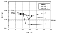
- FIG. 1 is a vertical cross-sectional view schematically showing a solid electrolytic capacitor according to an embodiment of the present disclosure. It is a graph showing the relationship between the temperature and loss modulus of resin contained in the exterior body of a solid electrolytic capacitor. It is a graph showing the relationship between the temperature and hardness of a resin part included in the exterior body of a solid electrolytic capacitor.
- the solid electrolytic capacitor according to this embodiment includes a capacitor element, a lead terminal electrically connected to the capacitor element, and an exterior body that seals a part of the lead terminal and the capacitor element.
- the exterior body includes a resin portion containing resin.
- the resin may be hereinafter referred to as "resin (R)".
- the hardness of the resin part measured by the nanoindentation method (in other words, the hardness found when the resin part is measured by the nanoindentation method) in the temperature range from the glass transition point Tg to 260°C ) is 0.08 GPa or less.
- the hardness of the resin portion measured by a nanoindentation method may be 0.08 GPa or less in a temperature range of 140° C. or higher and 260° C. or lower.
- the capacitor element can be improved by controlling the glass transition point Tg of the resin (R) contained in the exterior body and the hardness of the resin part containing the resin (R) in the exterior body.
- Tg glass transition point
- the resin (R) included in the exterior body of the solid electrolytic capacitor according to the present embodiment has a glass transition point Tg of 140° C. or less, and becomes a rubber state in a temperature range from the glass transition point Tg to 260° C. Furthermore, in this temperature range, the resin part containing the resin (R) has a low hardness of 0.08 GPa or less as measured by a nanoindentation method.
- Solid electrolytic capacitors are generally exposed to high temperatures (for example, temperatures in the range of 180° C. to 260° C.) during a reflow process and the like. Additionally, solid electrolytic capacitors may be used at high temperatures. When a solid electrolytic capacitor is exposed to high temperatures, each member of the solid electrolytic capacitor thermally expands. However, since each member has a different coefficient of thermal expansion, thermal stress occurs inside the solid electrolytic capacitor. As a result, when a conventional solid electrolytic capacitor is exposed to high temperatures, cracks and peeling tend to occur at the interface between the exterior body and the capacitor element and at the interface between the exterior body and the lead terminal.
- the solid electrolytic capacitor according to this embodiment When the solid electrolytic capacitor according to this embodiment is exposed to a temperature equal to or higher than the glass transition point Tg, the resin (R) contained in the exterior body becomes a rubber state, and the hardness of the resin part containing the resin (R) decreases. It is sufficiently low at 0.08 GPa or less. Therefore, the exterior body can disperse and relieve stress applied to the exterior body from the capacitor element and the lead terminal throughout the exterior body. As a result, it is possible to suppress the occurrence of cracks inside the exterior body, and it is also possible to suppress cracks and peeling that occur at the interface between the exterior body, the capacitor element, and the lead terminal. As described above, the solid electrolytic capacitor according to the present embodiment has a high sealability of the exterior body even at high temperatures, and has excellent heat resistance.
- the resin part contains resin (R).
- the resin part may be composed only of resin (R) or may contain components other than resin (R). Examples of components other than the resin (R) include a curing aid (hardening accelerator), a low stress agent (flexibility agent), a mold release agent, a coupling agent, a coloring agent, an ion trapping agent, and the like.
- the proportion of the resin (R) in the resin part may be in the range of 70 to 100% by mass, 80 to 100% by mass, or 90 to 100% by mass.
- the resin (R) contained in the resin part may be composed of only one type of resin, or may include multiple types of resin.
- the resin (R) contains multiple types of resins, it is sufficient that 50% by mass or more of the resins constituting the resin (R) satisfy the above condition (glass transition point Tg).
- the above condition glass transition point Tg
- all resins contained in the resin (R) satisfy the above condition (glass transition point Tg).
- the glass transition point Tg of the resin (R) can be determined by nanoscale dynamic viscoelasticity measurement (nanoDMA) using the nanoindentation method. For example, it is determined by cutting out a part of the exterior body and performing the measurement on the resin part of the cross section. Details of an example of the measurement method will be explained in Examples.
- the resin part contains a filler
- the measurement is carried out by bringing a triangular pyramid indenter into contact with the part where the filler is not present.
- the loss modulus of the resin (R) is measured at each temperature while increasing the temperature, a behavior in which the loss modulus increases and then decreases is observed. At this time, the temperature at which the loss modulus changes from increasing to decreasing is defined as the glass transition point Tg.
- the loss modulus of the resin part is measured while the resin part is heated by nanoscale dynamic viscoelasticity measurement using the nanoindentation method
- the temperature at which the loss modulus changes from increasing to decreasing is the temperature of the resin.
- the glass transition point of (R) is Tg.
- the loss modulus can be determined, for example, by performing dynamic viscoelasticity measurement at five arbitrary points on the resin part and finding the average value of the measured values.
- the glass transition point Tg of the resin (R) may be 125°C or lower.
- the exterior body can relax stress in a wide temperature range and maintain high sealing performance.
- the glass transition point Tg depends on the type, structure, crosslinking density, etc. of the resin. For example, by lowering the crosslinking density of the resin, the glass transition point Tg tends to decrease.
- the hardness of the resin part containing the resin (R) is also measured using the nanoindentation method in the same way as the glass transition point of the resin (R). For example, it can be determined by cutting out a part of the exterior body and continuously measuring the stiffness of the resin section of the cross section. Details of an example of the measurement method will be explained in Examples. When the resin part contains a filler, the measurement is carried out by bringing a triangular pyramid indenter into contact with the part where the filler is not present. Hardness can be determined, for example, by measuring arbitrary five points on the resin part and finding the average value of the measured values.
- the hardness of the resin part in the temperature range from the glass transition point Tg to 260°C is 0. It may be .05 GPa or less, or it may be 0.03 GPa or less. In another embodiment, the hardness of the resin portion in a temperature range of 140° C. or higher and 260° C. or lower may be 0.05 GPa or less, or 0.03 GPa or less.
- the hardness of the resin portion may be changed by changing the type, structure, crosslinking density, etc. of the resin (R). For example, when the distance between crosslinking points of the resin (R) contained in the resin part is increased, the hardness tends to decrease.
- the resin (R) is not particularly limited as long as it has the above properties.
- it may be a thermosetting resin or a thermoplastic resin.
- thermosetting resin examples include epoxy resin, phenol resin, urea resin, polyimide resin, polyamideimide resin, polyurethane resin, diallyl phthalate resin, and unsaturated polyester resin.
- resin (R) one type of these resins may be used alone, or two or more types may be used in combination.
- thermoplastic resin for example, polyphenylene sulfide (PPS), polybutylene terephthalate (PBT), etc. can be used.
- resin (R) one type of these resins may be used alone, or two or more types may be used in combination.
- the resin (R) may contain or be an epoxy resin.
- Epoxy resin has excellent electrical insulation, water resistance, chemical resistance, etc., and furthermore, the glass transition point Tg of the resin (R) and the hardness of the resin part can be easily controlled.
- Epoxy resins are generally obtained by a crosslinking reaction between a base material, which is a monomer or polymer (prepolymer) having an epoxy group, and a curing agent.
- a prepolymer such as a polyaromatic ring type epoxy resin, a biphenyl type epoxy resin, a cresol novolac type epoxy resin, a dicyclopentadiene type epoxy resin, etc. may be used.
- the polyaromatic epoxy resin is an epoxy resin that has a plurality of polyaromatic rings in its main skeleton.
- Polyaromatic epoxy resins have low viscosity at high temperatures. Therefore, for example, when the lead terminal is subjected to blasting, the adhesive strength between the lead terminal and the exterior body containing the polyaromatic ring type epoxy resin is physically increased due to the anchor effect.
- the glass transition point Tg of the resin (R) depends on the crosslinking density and structure of the epoxy resin. Therefore, the glass transition point Tg can be controlled by, for example, the types of the main agent and the curing agent, the blending ratio of the main agent and the curing agent, the molecular weight of the main agent, and the like. For example, when the concentration of functional groups (epoxy groups) in the base resin is low, or when the epoxy equivalent of the base resin is low, the crosslinking density of the epoxy resin tends to be low, and the glass transition point Tg tends to be low.
- the main ingredients have the same skeleton structure, the fewer the number of nuclei, the fewer the number of functional groups, the lower the crosslinking density of the epoxy resin, and the lower the glass transition point Tg.
- the base resin has a similar epoxy equivalent weight, the fewer the number of nuclei, the fewer the number of functional groups, the lower the crosslinking density of the epoxy resin, and the lower the glass transition point Tg.
- the glass transition point Tg tends to be high.
- the epoxy resin has a bulky substituent, the glass transition point Tg also tends to be high.
- the curing agent is not particularly limited and is appropriately selected depending on the type of the main ingredient.
- curing agents include polyfunctional or polyaromatic novolac curing agents such as phenol novolac, acid anhydride curing agents such as tetrahydrophthalic anhydride and hexahydrophthalic anhydride, and amines such as ethylenediamine and aromatic amines. Examples include hardening agents.
- a polymerization initiator, a catalyst, etc. may be used in addition to the base resin and the curing agent.
- the polymerization initiator, catalyst, etc. may also be selected appropriately depending on the type of the main ingredient.
- the catalyst include phosphorus compounds such as triphenylphosphine and its modified products, amines, and imidazoles.
- the exterior body may further include a filler dispersed in the resin portion.
- the exterior body may be comprised of a resin part and a filler dispersed in the resin part.
- the filler is dispersed in the resin part containing resin (R).
- the filler is not particularly limited, and any known filler can be used.
- insulating fillers such as insulating particles and insulating fibers are used.
- the insulating material constituting the insulating filler include insulating compounds such as silica, alumina, aluminum nitride, and boron nitride, glass, and mineral materials (talc, mica, clay, etc.).
- the number of fillers contained in the exterior body may be one, or two or more.
- the content of filler in the exterior body is preferably in the range of 75% by mass to 90% by mass. Further, the content may be 78% by mass or more and 86% by mass or less.
- the maximum particle size of the filler may be 100 ⁇ m or less (for example, 55 ⁇ m or less). By setting the maximum particle size to 55 ⁇ m or less, stress can be easily relaxed as described above.
- the maximum particle size refers to the particle size of the largest particle among the filler particles contained in the exterior body.
- the maximum particle size is determined by photographing a cross section of the outer package, arbitrarily selecting 100 particles, and measuring the cross-sectional area of the particles. Among the equivalent circles having the same area as the cross-sectional area of each particle, the diameter of the largest equivalent circle is the maximum particle size.
- the solid electrolytic capacitor according to this embodiment has high heat resistance, and the sealing performance of the exterior body is maintained even at high temperatures. Therefore, moisture and oxygen are prevented from entering the solid electrolytic capacitor, and deterioration of the conductive polymer in the solid electrolyte contained in the capacitor element is less likely to occur. Therefore, even when exposed to high temperatures, the capacitance and ESR of the solid electrolytic capacitor are maintained.
- Capacitance change rate (%) 100 x (C1-C0)/C0 (In the formula, C0 is the initial capacitance, and C1 is the capacitance after heating at 125°C for 7000 hours.)
- the average value of the capacitance change rate expressed by may be ⁇ 5.0% or more.
- the average value may be -3.0% or more, or -1.0% or more.
- the average value is an average value of the capacitance change rates of at least 60 (for example, 100) solid electrolytic capacitors.
- Capacitance can be measured using, for example, an LCR meter.
- the capacitance change rate of one solid electrolytic capacitor is preferably -5.0% or more, more preferably -3.0% or more.
- the solid electrolytic capacitor according to the present embodiment includes a capacitor element, a lead terminal, and an exterior body, and includes other components as necessary.
- An example of the structure of a solid electrolytic capacitor will be described below.
- the configuration of the solid electrolytic capacitor is not limited to the following example.
- a known configuration may be applied to the configuration other than the configuration characteristic of the solid electrolytic capacitor according to this embodiment.
- the solid electrolytic capacitor may include a case made of metal or the like in addition to the above-described exterior body.
- Solid electrolytic capacitors have one or more capacitor elements. Note that the number of capacitor elements included in a solid electrolytic capacitor is determined depending on the application. When including two or more capacitor elements, the capacitor elements are typically stacked. In this case, an anode lead terminal is connected to an anode stacked part in which a plurality of anode parts are stacked, and a cathode lead terminal is connected to a cathode stacked part in which a plurality of cathode parts are stacked.
- the anode body can include a valve metal, an alloy containing a valve metal, a compound containing a valve metal, and the like. These materials may be used alone or in combination of two or more.
- the valve metal for example, aluminum, tantalum, niobium, and titanium are preferably used.
- the surface of the anode body may have a porous structure.
- a porous structure can be obtained by roughening the surface of a base material (such as a foil-like or plate-like base material) containing a valve metal by etching or the like.
- the anode body may be a molded body of particles containing a valve metal or a sintered body thereof.
- the anode portion may include an anode wire partially embedded in the sintered body. In that case, one end of the anode lead terminal is connected to the anode wire.
- the dielectric layer is an insulating layer formed to cover at least a portion of the surface of the anode body. Although not particularly limited as long as it functions as a dielectric layer, it is formed, for example, by anodic oxidation of the valve metal on the surface of the anode body by chemical conversion treatment or the like.
- the dielectric layer includes an oxide of a valve metal.
- the dielectric layer contains Ta 2 O 5 when tantalum is used as the valve metal, and the dielectric layer contains Al 2 O 3 when aluminum is used as the valve metal.
- the solid electrolyte layer is formed to cover at least a portion of the dielectric layer.
- the solid electrolyte layer contains a conductive polymer.
- a conductive polymer polypyrrole, polythiophene, polyfuran, polyaniline, polyacetylene, polyphenylene, polyphenylene vinylene, polyacene, polythiophene vinylene, and derivatives thereof can be used. Examples of the derivative include poly(3,4-ethylenedioxythiophene).
- a dopant may be added to the conductive polymer.
- the dopant can be selected depending on the conductive polymer, and known dopants may be used. Examples of dopants include naphthalenesulfonic acid, p-toluenesulfonic acid, polystyrenesulfonic acid, and salts thereof.
- a solid electrolyte layer containing a conductive polymer may be formed by polymerizing a monomer as a raw material on a dielectric layer.
- a solid electrolyte layer may be formed by disposing a liquid containing a conductive polymer on a dielectric layer and then drying the liquid.
- the cathode extraction layer only needs to include a first layer that covers at least a portion of the solid electrolyte layer, and may include a first layer and a second layer that covers the first layer. Both the first layer and the second layer are conductive layers.
- the first layer is formed of, for example, a layer containing conductive particles, metal foil, or the like. Examples of the conductive particles include conductive carbon and metal powder.
- the second layer is formed of, for example, a layer containing metal powder or metal foil.
- the layer containing metal powder is formed using, for example, a composition (metal paste) containing metal powder such as silver particles and a resin (binder resin).
- the adhesive layer connects the cathode lead terminal and the cathode section.
- the adhesive layer includes conductive particles. Examples of the conductive particles include metal particles (eg, silver particles).
- the adhesive layer is formed using a metal paste containing metal particles and resin.
- the lead terminals include an anode lead terminal and a cathode lead terminal. One end side of the anode lead terminal and the cathode lead terminal is sealed together with the capacitor element by an exterior body. One end of the anode lead terminal is electrically connected to the anode of the capacitor element, and the other end is exposed to the outside of the exterior body. One end of the cathode lead terminal is electrically connected to the cathode of the capacitor element, and the other end is exposed to the outside of the exterior body.
- the anode lead terminal and cathode lead terminal exposed from the exterior body are used for solder connection to a board on which the solid electrolytic capacitor is mounted.
- lead terminals generally used in solid electrolytic capacitors can be used without particular restriction.
- the material include metals such as copper or alloys thereof.
- the surfaces of the anode lead terminal and the cathode lead terminal may be subjected to blasting treatment. Blasting improves the adhesion strength between the lead terminal and the exterior body, making it difficult for cracks and peeling to occur at the interface.
- the exterior body seals the capacitor element and a portion of the anode lead terminal and the cathode lead terminal.
- the exterior body described above is used as the exterior body.
- the exterior body can be formed using molding techniques such as injection molding, insert molding, and compression molding.
- An uncured resin mixture is used for molding.
- a resin mixture containing a base material (monomer, prepolymer, etc.) that is a raw material for the resin (R), a curing agent, a filler, etc. is used.
- the molding is performed, for example, by using a predetermined mold and filling a predetermined location with a resin mixture so as to cover the capacitor element and one end of the lead terminal.
- the resin mixture is cured by molding, and an exterior body including a resin part containing resin (R) is formed.
- a capacitor element includes a step of forming a dielectric layer to cover at least a portion of an anode body, a step of forming a solid electrolyte layer to cover at least a portion of the dielectric layer, and a step of forming a solid electrolyte layer to cover at least a portion of the dielectric layer. It is manufactured by a manufacturing method that includes a step of forming a cathode extraction layer on a portion.
- the step of forming the cathode extraction layer includes, for example, a step of forming a carbon layer and a step of forming a silver paste layer on at least a portion of the carbon layer.
- the method may include a step of preparing an anode body prior to the step of forming the dielectric layer.
- a solid electrolytic capacitor is manufactured by a manufacturing method that includes, for example, a step of electrically connecting a lead terminal to a capacitor element, and a step of covering a portion of the capacitor element and the lead terminal with an exterior body (sealing step).
- the solid electrolytic capacitor may be of a wound type, a chip type, or a laminated type.
- FIG. 1 The configuration of an example of the solid electrolytic capacitor according to this embodiment will be explained using FIG. 1.
- the above-mentioned components can be applied to the example components described below. Further, the constituent elements of the example described below can be changed based on the above description.
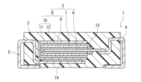
- FIG. 1 is a cross-sectional view schematically showing the structure of an example solid electrolytic capacitor 1 according to the present embodiment.
- Solid electrolytic capacitor 1 includes a capacitor element 2, lead terminals (anode lead terminal 4 and cathode lead terminal 5), and an exterior body 3 that seals a portion of the lead terminal and capacitor element 2. A portion of the anode lead terminal 4 and a portion of the cathode lead terminal 5 are exposed from the exterior body 3.
- the exterior body described above is used for the exterior body 3.
- the capacitor element 2 includes an anode body 6 constituting an anode part, a dielectric layer 7 covering the anode body 6, and a cathode part 8 covering the dielectric layer 7.
- the anode body 6 includes a region facing the cathode section 8 and a region not facing the cathode section 8.
- An insulating separation layer 13 is formed in a region adjacent to the cathode part 8 of the anode body 6 that does not face the cathode part 8 so as to cover the surface of the anode body 6 in a band-like manner. Contact with the body 6 is regulated.
- the other part of the region of the anode body 6 that does not face the cathode section 8 is electrically connected to the anode lead terminal 4 by welding.
- the cathode lead terminal 5 is electrically connected to the cathode section 8 via an adhesive layer 14 formed of a conductive adhesive.
- the cathode section 8 includes a solid electrolyte layer 9 covering the dielectric layer 7 and a cathode extraction layer 10 covering the solid electrolyte layer 9.
- the cathode extraction layer 10 has a carbon layer 11 and a silver paste layer 12.
- a solid electrolytic capacitor including a capacitor element, a lead terminal electrically connected to the capacitor element, and an exterior body that seals a part of the lead terminal and the capacitor element,
- the exterior body includes a resin part containing resin,
- the glass transition point Tg of the resin the glass transition point Tg is 140°C or less
- Capacitance change rate (%) 100 x (C1-C0)/C0 (In the formula, C0 is the initial capacitance, and C1 is the capacitance after heating at 125°C for 7000 hours.)
- Solid electrolytic capacitors A1, B1, and B2 were produced in the following manner.
- a silver paste containing silver particles and a binder resin epoxy resin
- the binder resin was cured by heating at 150° C. for 30 minutes to form a silver paste layer.
- a cathode extraction layer composed of a carbon layer and a silver paste layer was formed, and a cathode section including a solid electrolyte layer and a cathode extraction layer was formed.
- a capacitor element was produced through the steps (1-a) to (1-d).
- the following resin mixtures 1 to 3 were used to form an exterior body around the capacitor element and lead terminals by molding. At this time, the other end of the anode lead terminal and the other end of the cathode lead terminal were exposed from the exterior body. In this way, solid electrolytic capacitors A1, B1, and B2 were completed.
- the following resin mixture 1 was used for the solid electrolytic capacitor A1
- the following resin mixture 2 was used for the solid electrolytic capacitor B1
- the following resin mixture 3 was used for the solid electrolytic capacitor B2.
- the resin part of the exterior body formed of the resin mixture 1 contains a polyaromatic ring type epoxy resin as the resin (R). Note that filler is dispersed in the following resin mixture.
- Resin mixture 1 The glass transition point Tg measured by nanoDMA in the resin part formed by curing is around 125°C, and the hardness of the resin part is 0.08 or less in a temperature range higher than the glass transition point Tg. resin mixture.
- Resin mixture 2 The glass transition point Tg measured by nanoDMA in the resin part formed by curing is around 145°C, and the hardness of the resin part is less than 0.08 in a temperature range higher than the glass transition point Tg. Large resin mixture.
- Resin mixture 3 The glass transition point Tg measured by nanoDMA in the resin part formed by curing is around 165°C, and the hardness of the resin part is 0.08 or higher in a temperature range higher than the glass transition point Tg. Large resin mixture.
- Nanoscale dynamic viscoelasticity measurements were performed using the following method.
- a diamond triangular pyramid indenter (Berkovich indenter) was brought into contact with a portion (resin portion) that did not include filler in the cross section of the sample, and the indenter was caused to vibrate minutely.
- the response amplitude and phase difference to the vibrations were obtained as a function of time, and the stiffness and sample damping were calculated.
- the loss modulus was calculated using the calculated sample damping results. The loss modulus at each temperature was determined by calculating the average value of the measured values at five points. The results are shown in Figure 2.
- the glass transition point Tg The glass transition points Tg of the resins contained in the exterior bodies of solid electrolytic capacitors A1, B1, and B2 were 125°C, about 145°C (temperature in the range of 145°C to 165°C), and 165°C, respectively.
- the hardness of the resin part included in the solid electrolytic capacitor A1 was 0.08 GPa or less in a temperature range from the glass transition point Tg (125°C) of the resin to 260°C.
- the hardness of the resin parts included in solid electrolytic capacitors B1 and B2 is 260°C above the glass transition point Tg of the resin (resin of solid electrolytic capacitor B1: approximately 145°C, resin of solid electrolytic capacitor B2: 165°C). In the following temperature ranges, the values were higher than 0.08 GPa.
- solid electrolytic capacitor A1 is the solid electrolytic capacitor according to the present embodiment.
- Solid electrolytic capacitors B1 and B2 are solid electrolytic capacitors of comparative examples.
- each solid electrolytic capacitor In an environment of 20° C., the capacitance ( ⁇ F) of each solid electrolytic capacitor at a frequency of 120 Hz was measured as the initial capacitance C0 ( ⁇ F) using an LCR meter for four-terminal measurement. Thereafter, each solid electrolytic capacitor was heated under the same temperature conditions as the reflow treatment according to IPC/JEDEC J-STD-020D (heating at a maximum temperature of 260° C. and above 255° C. for 30 seconds). Next, a high temperature storage test was conducted in which the solid electrolytic capacitor was left in an environment of 125° C. for 7000 hours.
- Capacitance change rate (%) 100 x (C1-C0)/C0
- the average value was determined by arithmetic averaging the capacitance change rates of 100 solid electrolytic capacitors A1. Similarly, the average value of the capacitance change rate of 60 solid electrolytic capacitors B1 and the average value of the capacitance change rate of 60 solid electrolytic capacitors B2 were determined. The evaluation results are shown in Table 1. As the deterioration of the solid electrolytic capacitor increases, the capacitance change rate becomes negative. A capacitance change rate close to 0 (or positively large) indicates that the solid electrolytic capacitor has little deterioration.
- the average value of the capacitance change rate of solid electrolytic capacitor A1 after the high temperature storage test is -5% or more (i.e. -5.0 ⁇ 100 ⁇ (C1-C0)/C0).
- the solid electrolytic capacitor deteriorates less (that is, the value of the capacitance change rate changes more to the positive side).
- the average value of the capacitance change rate after the high temperature storage test of solid electrolytic capacitors B1 and B2 was lower than -5%. This means that solid electrolytic capacitor A1, unlike solid electrolytic capacitors B1 and B2, exhibits less decrease in capacitance even when exposed to high temperatures for a long time.
- ESR change rate Changes in ESR (equivalent series resistance) of solid electrolytic capacitors A1, B1, and B2 at 125° C. were measured using the following procedure.
- the ESR change rates of 100 solid electrolytic capacitors A1 were arithmetic averaged to obtain an average value.
- the average value of the ESR change rate of 60 solid electrolytic capacitors B1 and the average value of the ESR change rate of 60 solid electrolytic capacitors B2 were determined. The results are shown in Table 2. As the deterioration of the solid electrolytic capacitor increases, the ESR change rate increases. The smaller the ESR change rate, the less deterioration of the solid electrolytic capacitor.
- the ESR change rate of solid electrolytic capacitor A1 was a significantly lower value than the ESR change rate of solid electrolytic capacitors B1 and B2.
- each solid electrolytic capacitor was placed inside a small capsule, and the minute pressure drop caused by the internal pressure inside the small capsule leaking into the exterior body was measured. Then, a capacitor whose pressure change at this time was larger than a predetermined value was determined to have poor airtightness, and the percentage of poor airtightness (%) was determined.
- the solid electrolytic capacitor A1 is the solid electrolytic capacitor according to the present embodiment. It was confirmed that in the solid electrolytic capacitor A1, a decrease in capacitance and an increase in ESR were suppressed even when exposed to high temperatures.
- the resin contained in the exterior body of the solid electrolytic capacitor A1 is in a rubber state at 125° C. when the high temperature storage test was conducted, and the hardness of the resin part containing the resin is as low as 0.08 GPa or less. Therefore, it is thought that the stress applied to the exterior body from the capacitor element and the lead terminals can be alleviated in the entire exterior body, suppressing the occurrence of cracks and peeling, and improving airtightness. As a result, it is presumed that the exterior body was able to maintain high sealing performance even under high temperatures.
- the solid electrolytic capacitor of the present disclosure has a high sealability of the exterior body even at high temperatures, and can suppress a decrease in capacitance and an increase in ESR. Therefore, it can be used in various applications that require high reliability.
- Electrolytic capacitor Capacitor element 3 Exterior body 4 Anode lead terminal 5 Cathode lead terminal 6 Anode body 7 Dielectric layer 8 Cathode part 9 Solid electrolyte layer 10 Cathode extraction layer 11 Carbon layer 12 Silver paste layer 13 Separation layer 14 Adhesive layer
Abstract
A solid electrolytic capacitor (1) according to the present disclosure comprises: a capacitor element (2); a lead terminal (4) and a lead terminal (5), which are electrically connected to the capacitor element (2); and an outer case (3) which seals a part of the lead terminal (4), a part of the lead terminal (5) and the capacitor element (2). The outer case (3) comprises a resin part that contains a resin. In the resin part, if a glass transition temperature Tg of the resin is the temperature at which the loss elastic modulus stops increasing and takes a downward turn as determined by nanoscale dynamic viscoelasticity measurement that utilizes a nanoindentation method, the glass transition temperature Tg is 140°C or less; and within the temperature range from the glass transition temperature Tg to 260°C, the hardness of the resin part as determined by the nanoindentation method is 0.08 GPa or less.
Description
本開示は、固体電解コンデンサに関する。
The present disclosure relates to solid electrolytic capacitors.
固体電解コンデンサは、等価直列抵抗(ESR)が低く、周波数特性に優れているため、様々な電子機器に搭載されている。固体電解コンデンサは、コンデンサ素子と、コンデンサ素子と電気的に接続されているリード端子と、リード端子の一部とコンデンサ素子とを封止する外装体とを含む。コンデンサ素子に含まれる電解質として、固体である導電性高分子を使用することにより、固体電解コンデンサは低いESRと優れた周波数特性を示す。
Solid electrolytic capacitors have low equivalent series resistance (ESR) and excellent frequency characteristics, so they are installed in various electronic devices. A solid electrolytic capacitor includes a capacitor element, a lead terminal electrically connected to the capacitor element, and an exterior body that seals a portion of the lead terminal and the capacitor element. By using a solid conductive polymer as the electrolyte contained in the capacitor element, solid electrolytic capacitors exhibit low ESR and excellent frequency characteristics.
固体電解コンデンサは、一般に、高温に曝されるリフロー工程を経て基板にはんだ接合される。その際、熱応力により外装体にクラックが形成され、外装体の封止性が低くなることがある。封止性が低下すると、固体電解コンデンサ内部に侵入した水分や酸素によって、固体電解質層に含まれる導電性高分子が酸化して劣化する。この結果、固体電解質層の導電性が低下し、固体電解コンデンサの静電容量の低下やESRの増大が引き起こされる。したがって、外装体の封止性を向上させることを目的とした様々な固体電解コンデンサが提案されている。
Solid electrolytic capacitors are generally soldered to a substrate through a reflow process that involves exposure to high temperatures. At that time, cracks may be formed in the exterior body due to thermal stress, and the sealing performance of the exterior body may be reduced. When the sealing performance deteriorates, the conductive polymer contained in the solid electrolyte layer is oxidized and deteriorated by moisture and oxygen that have entered the solid electrolytic capacitor. As a result, the conductivity of the solid electrolyte layer decreases, causing a decrease in capacitance and an increase in ESR of the solid electrolytic capacitor. Therefore, various solid electrolytic capacitors have been proposed with the aim of improving the sealing performance of the exterior body.
例えば、特許文献1は、「固体電解キャパシタであって、焼結多孔質陽極体、前記陽極体の上に配されている誘電体、及び前記誘電体の上に配されている固体電解質を含むキャパシタ素子;前記キャパシタ素子の表面から延在する陽極リード;前記陽極リードと電気的に接続されている陽極終端、及び前記固体電解質と電気的に接続されている陰極終端;並びに前記キャパシタ素子及び前記陽極リードを封入しているケーシング材料であって、前記ケーシング材料は、樹脂状マトリクスのガラス転移温度より高い温度において約42ppm/℃以下の熱膨張係数を有する硬化性樹脂状マトリクスから形成されている上記ケーシング材料;を含み;前記キャパシタは、100kHzの動作周波数及び23℃の温度において求めて約200ミリオーム以下の初期等価直列抵抗を示し、前記キャパシタの初期等価直列抵抗に対する、125℃の温度に560時間曝露した後の前記キャパシタの等価直列抵抗の比は約2.0以下である、上記固体電解キャパシタ。」を開示している。
For example, Patent Document 1 describes "a solid electrolytic capacitor including a sintered porous anode body, a dielectric body disposed on the anode body, and a solid electrolyte disposed on the dielectric body. a capacitor element; an anode lead extending from the surface of the capacitor element; an anode termination electrically connected to the anode lead; and a cathode termination electrically connected to the solid electrolyte; A casing material enclosing an anode lead, the casing material being formed from a curable resinous matrix having a coefficient of thermal expansion of less than about 42 ppm/° C. at temperatures above the glass transition temperature of the resinous matrix. said casing material; said capacitor exhibiting an initial equivalent series resistance of less than about 200 milliohms as determined at an operating frequency of 100 kHz and a temperature of 23°C; The solid electrolytic capacitor, wherein the ratio of equivalent series resistance of the capacitor after exposure for a period of time is less than or equal to about 2.0.
高温下、固体電解コンデンサの内部では、外装体、コンデンサ素子、リード端子などの熱膨張および熱収縮が生じる。外装体は、コンデンサ素子を封止すると同時にリード端子の一部も封止していることから、外装体に対しては、コンデンサ素子およびリード端子からの応力も加わる。そのため、外装体内部にはクラックが形成されやすくなる。同時に、外装体とコンデンサ素子との界面、および外装体とリード端子との界面にもクラックや剥離が形成されやすくなる。
At high temperatures, thermal expansion and contraction of the exterior body, capacitor element, lead terminals, etc. occur inside a solid electrolytic capacitor. Since the exterior body seals the capacitor element and also partially seals the lead terminals, stress from the capacitor element and the lead terminals is also applied to the exterior body. Therefore, cracks are likely to form inside the exterior body. At the same time, cracks and peeling are likely to be formed at the interface between the exterior body and the capacitor element, and at the interface between the exterior body and the lead terminal.
これら内部応力に起因するクラックや剥離の形成を抑制し、外装体の封止性を向上させるために、従来技術のように、外装体の熱膨張および熱収縮を軽減させる手法も存在する。しかし、外装体の熱膨張係数と、被着体であるコンデンサ素子およびリード端子の熱膨張係数との相互関係によっては、内部応力を増長させる可能性があり、従来技術のような手法では技術施策として不十分である。したがって、内部応力に単独寄与する外装体の材料物性、すなわち外装体の弾性率および硬さを規定することが、外装体と、コンデンサ素子およびリード端子との界面で生じるクラックや剥離を抑制し、封止性を向上させるために重要である。
In order to suppress the formation of cracks and peeling caused by these internal stresses and to improve the sealing properties of the exterior body, there are also methods to reduce the thermal expansion and contraction of the exterior body, as in the prior art. However, depending on the interrelationship between the thermal expansion coefficient of the exterior body and the thermal expansion coefficients of the capacitor element and lead terminals, which are adherends, internal stress may increase, and conventional techniques do not require technical measures. This is insufficient. Therefore, specifying the material properties of the exterior body that independently contribute to internal stress, that is, the elastic modulus and hardness of the exterior body, can suppress cracks and peeling that occur at the interface between the exterior body, capacitor element, and lead terminal, and This is important for improving sealing performance.
このような状況において、本開示の目的は、高温下でも外装体の封止性が高い、耐熱性に優れる固体電解コンデンサを提供することである。
Under such circumstances, an object of the present disclosure is to provide a solid electrolytic capacitor with excellent heat resistance and whose outer casing has high sealability even at high temperatures.
本開示は、固体電解コンデンサに関する。当該固体電解コンデンサは、コンデンサ素子と、前記コンデンサ素子と電気的に接続されているリード端子と、前記リード端子の一部と前記コンデンサ素子とを封止する外装体と、を含む固体電解コンデンサであって、前記外装体は、樹脂を含有する樹脂部を含み、前記樹脂部においてナノインデンテーション法を利用したナノスケール動的粘弾性測定によって測定される損失弾性率が増加から減少に転ずる温度を前記樹脂のガラス転移点Tgとしたとき、前記ガラス転移点Tgが140℃以下であり、前記ガラス転移点Tg以上で260℃以下の温度範囲において、ナノインデンテーション法で測定される前記樹脂部の硬さは0.08GPa以下である。
The present disclosure relates to solid electrolytic capacitors. The solid electrolytic capacitor is a solid electrolytic capacitor that includes a capacitor element, a lead terminal electrically connected to the capacitor element, and an exterior body that seals a part of the lead terminal and the capacitor element. The exterior body includes a resin part containing a resin, and the temperature at which the loss modulus of the resin part changes from increasing to decreasing as measured by nanoscale dynamic viscoelasticity measurement using the nanoindentation method. The glass transition point Tg of the resin is 140° C. or lower, and the resin portion is measured by a nanoindentation method in a temperature range of not less than the glass transition point Tg and not more than 260° C. The hardness is 0.08 GPa or less.
組み合わせが可能である限り、添付の特許請求の範囲に記載の複数の請求項から任意に選択される2つ以上の請求項に記載の事項を組み合わせてもよい。また、組み合わせが可能である限り、実施形態に記載の構成は、任意に組み合わせてもよい。
As long as a combination is possible, the matters described in two or more claims arbitrarily selected from the plurality of claims described in the appended claims may be combined. Furthermore, the configurations described in the embodiments may be combined in any desired manner as long as such combinations are possible.
本開示によれば、耐熱性に優れた固体電解コンデンサが得られる。
本発明の新規な特徴を添付の請求の範囲に記述するが、本発明は、構成および内容の両方に関し、本発明の他の目的および特徴と併せ、図面を照合した以下の詳細な説明によりさらによく理解されるであろう。 According to the present disclosure, a solid electrolytic capacitor with excellent heat resistance can be obtained.
While the novel features of the invention are set forth in the appended claims, the invention is further understood by the following detailed description, taken together with the drawings, both as to structure and content, as well as other objects and features of the invention. It will be well understood.
以下では、本開示に係る実施形態について例を挙げて説明するが、本開示は以下で説明する例に限定されない。以下の説明では、具体的な数値や材料を例示する場合があるが、本開示に係る発明を実施できる限り、他の数値や他の材料を適用してもよい。この明細書において、「数値A~数値B」という記載は、数値Aおよび数値Bを含み、「数値A以上で数値B以下」と読み替えることが可能である。以下の説明において、特定の物性や条件などに関する数値の下限と上限とを例示した場合、下限が上限以上とならない限り、例示した下限のいずれかと例示した上限のいずれかとを任意に組み合わせることができる。
Hereinafter, embodiments according to the present disclosure will be described using examples, but the present disclosure is not limited to the examples described below. In the following description, specific numerical values and materials may be illustrated, but other numerical values and other materials may be applied as long as the invention according to the present disclosure can be implemented. In this specification, the expression "numerical value A to numerical value B" includes numerical value A and numerical value B, and can be read as "more than or equal to numerical value A and less than or equal to numerical value B." In the following explanation, when lower and upper limits of numerical values related to specific physical properties or conditions are illustrated, any of the illustrated lower limits and any of the illustrated upper limits can be arbitrarily combined as long as the lower limit is not greater than the upper limit. .
本実施形態に係る固体電解コンデンサは、コンデンサ素子と、コンデンサ素子と電気的に接続されているリード端子と、リード端子の一部とコンデンサ素子とを封止する外装体とを含む。外装体は、樹脂を含有する樹脂部を含む。当該樹脂を以下では、「樹脂(R)」と称する場合がある。当該樹脂部においてナノインデンテーション法を利用したナノスケール動的粘弾性測定によって測定される損失弾性率が増加から減少に転ずる温度を樹脂(R)のガラス転移点Tgとしたとき、ガラス転移点Tgは140℃以下である。また、ガラス転移点Tg以上で260℃以下の温度範囲において、ナノインデンテーション法で測定される樹脂部の硬さ(換言すれば、ナノインデンテーション法で樹脂部を測定したときに求められる硬さ)は0.08GPa以下である。別の一態様では、140℃以上で260℃以下の温度範囲において、ナノインデンテーション法で測定される樹脂部の硬さは0.08GPa以下であってもよい。
The solid electrolytic capacitor according to this embodiment includes a capacitor element, a lead terminal electrically connected to the capacitor element, and an exterior body that seals a part of the lead terminal and the capacitor element. The exterior body includes a resin portion containing resin. The resin may be hereinafter referred to as "resin (R)". When the temperature at which the loss modulus changes from increasing to decreasing as measured by nanoscale dynamic viscoelasticity measurement using the nanoindentation method in the resin part is the glass transition point Tg of the resin (R), the glass transition point Tg is below 140°C. In addition, the hardness of the resin part measured by the nanoindentation method (in other words, the hardness found when the resin part is measured by the nanoindentation method) in the temperature range from the glass transition point Tg to 260°C ) is 0.08 GPa or less. In another aspect, the hardness of the resin portion measured by a nanoindentation method may be 0.08 GPa or less in a temperature range of 140° C. or higher and 260° C. or lower.
上述したように、固体電解コンデンサの耐熱性を向上させるためには、外装体と、コンデンサ素子およびリード端子との界面で生じるクラックや剥離の抑制が重要となる。検討の結果、本願発明者らは、外装体において、外装体に含まれる樹脂(R)のガラス転移点Tgと、樹脂(R)を含有する樹脂部の硬さとを制御することにより、コンデンサ素子およびリード端子から外装体に加わる応力が緩和されることを新たに見出した。
As mentioned above, in order to improve the heat resistance of solid electrolytic capacitors, it is important to suppress cracks and peeling that occur at the interfaces between the exterior body, capacitor elements, and lead terminals. As a result of the study, the inventors of the present invention found that the capacitor element can be improved by controlling the glass transition point Tg of the resin (R) contained in the exterior body and the hardness of the resin part containing the resin (R) in the exterior body. We have also newly discovered that the stress applied to the exterior body from the lead terminals is alleviated.
ガラス転移点Tgを有する樹脂は、昇温すると、ガラス転移点Tgでガラス状態からゴム状態へと変化する。本実施形態に係る固体電解コンデンサの外装体に含まれる樹脂(R)は、ガラス転移点Tgが140℃以下であり、ガラス転移点Tg以上、260℃以下の温度範囲でゴム状態となる。さらに、この温度範囲において、樹脂(R)を含有する樹脂部は、ナノインデンテーション法で測定される硬さが0.08GPa以下と低い。
When a resin having a glass transition point Tg is heated, it changes from a glass state to a rubber state at the glass transition point Tg. The resin (R) included in the exterior body of the solid electrolytic capacitor according to the present embodiment has a glass transition point Tg of 140° C. or less, and becomes a rubber state in a temperature range from the glass transition point Tg to 260° C. Furthermore, in this temperature range, the resin part containing the resin (R) has a low hardness of 0.08 GPa or less as measured by a nanoindentation method.
固体電解コンデンサは、一般に、リフロー工程などで高温(例えば180℃~260℃の範囲の温度)に曝される。また、固体電解コンデンサは、高温で使用される場合もある。固体電解コンデンサが高温に曝されたときには、固体電解コンデンサの各部材が熱膨張する。しかし、それぞれの部材の熱膨張係数は異なるため、固体電解コンデンサの内部で熱応力が発生する。その結果、従来の固体電解コンデンサが高温に曝されたときには、外装体とコンデンサ素子との界面や外装体とリード端子との界面において、クラックや剥離が発生しやすくなる。
Solid electrolytic capacitors are generally exposed to high temperatures (for example, temperatures in the range of 180° C. to 260° C.) during a reflow process and the like. Additionally, solid electrolytic capacitors may be used at high temperatures. When a solid electrolytic capacitor is exposed to high temperatures, each member of the solid electrolytic capacitor thermally expands. However, since each member has a different coefficient of thermal expansion, thermal stress occurs inside the solid electrolytic capacitor. As a result, when a conventional solid electrolytic capacitor is exposed to high temperatures, cracks and peeling tend to occur at the interface between the exterior body and the capacitor element and at the interface between the exterior body and the lead terminal.
本実施形態に係る固体電解コンデンサがガラス転移点Tg以上の温度に曝された場合、外装体に含まれる樹脂(R)はゴム状態となり、さらに樹脂(R)を含有する樹脂部の硬さは0.08GPa以下と十分に低くなる。そのため、外装体は、コンデンサ素子およびリード端子から外装体に加わる応力を外装体全体に分散して緩和することができる。その結果、外装体内部のクラックの発生を抑制できるとともに、外装体と、コンデンサ素子およびリード端子との界面で生じるクラックや剥離も抑制できる。以上のように、本実施形態に係る固体電解コンデンサは、高温下でも外装体の封止性が高く、耐熱性に優れる。
When the solid electrolytic capacitor according to this embodiment is exposed to a temperature equal to or higher than the glass transition point Tg, the resin (R) contained in the exterior body becomes a rubber state, and the hardness of the resin part containing the resin (R) decreases. It is sufficiently low at 0.08 GPa or less. Therefore, the exterior body can disperse and relieve stress applied to the exterior body from the capacitor element and the lead terminal throughout the exterior body. As a result, it is possible to suppress the occurrence of cracks inside the exterior body, and it is also possible to suppress cracks and peeling that occur at the interface between the exterior body, the capacitor element, and the lead terminal. As described above, the solid electrolytic capacitor according to the present embodiment has a high sealability of the exterior body even at high temperatures, and has excellent heat resistance.
(樹脂部)
樹脂部は、樹脂(R)を含む。樹脂部は、樹脂(R)のみで構成されていてもよいし、樹脂(R)以外の成分を含んでもよい。樹脂(R)以外の成分の例には、硬化助剤(硬化促進剤)、低応力剤(可とう剤)、離型剤、カップリング剤、着色剤、イオン捕捉剤などが含まれる。樹脂部に占める樹脂(R)の割合は、70~100質量%の範囲、80~100質量%の範囲、または90~100質量%の範囲にあってもよい。 (Resin part)
The resin part contains resin (R). The resin part may be composed only of resin (R) or may contain components other than resin (R). Examples of components other than the resin (R) include a curing aid (hardening accelerator), a low stress agent (flexibility agent), a mold release agent, a coupling agent, a coloring agent, an ion trapping agent, and the like. The proportion of the resin (R) in the resin part may be in the range of 70 to 100% by mass, 80 to 100% by mass, or 90 to 100% by mass.
(樹脂(R))
樹脂部に含有される樹脂(R)は、1種の樹脂のみで構成されてもよく、複数種の樹脂を含んでもよい。樹脂(R)が複数種の樹脂を含む場合、樹脂(R)を構成する樹脂の50質量%以上が上記の条件(ガラス転移点Tg)を満たせばよい。好ましくは、樹脂(R)に含まれるすべての樹脂が上記の条件(ガラス転移点Tg)を満たす。 (Resin (R))
The resin (R) contained in the resin part may be composed of only one type of resin, or may include multiple types of resin. When the resin (R) contains multiple types of resins, it is sufficient that 50% by mass or more of the resins constituting the resin (R) satisfy the above condition (glass transition point Tg). Preferably, all resins contained in the resin (R) satisfy the above condition (glass transition point Tg).
樹脂(R)のガラス転移点Tgは、ナノインデンテーション法を利用したナノスケール動的粘弾性測定(ナノDMA)により求めることができる。例えば、外装体の一部を切り出し、その断面の樹脂部について当該測定を行うことにより求められる。測定方法の一例の詳細は、実施例で説明する。樹脂部がフィラーを含む場合には、フィラーの存在しない箇所に三角錐圧子を接触させて測定する。昇温しながら各温度での樹脂(R)の損失弾性率を測定すると、損失弾性率が増加した後、減少する挙動が観察される。このとき、損失弾性率が増加から減少に転ずる温度をガラス転移点Tgとする。すなわち、ナノインデンテーション法を利用したナノスケール動的粘弾性測定によって、樹脂部を昇温しながら当該樹脂部の損失弾性率を測定したときに、損失弾性率が増加から減少に転ずる温度を樹脂(R)のガラス転移点Tgとする。なお、損失弾性率は、例えば、樹脂部の任意の5点に対して動的粘弾性測定を行い、測定値の平均値を求めることにより決定できる。
The glass transition point Tg of the resin (R) can be determined by nanoscale dynamic viscoelasticity measurement (nanoDMA) using the nanoindentation method. For example, it is determined by cutting out a part of the exterior body and performing the measurement on the resin part of the cross section. Details of an example of the measurement method will be explained in Examples. When the resin part contains a filler, the measurement is carried out by bringing a triangular pyramid indenter into contact with the part where the filler is not present. When the loss modulus of the resin (R) is measured at each temperature while increasing the temperature, a behavior in which the loss modulus increases and then decreases is observed. At this time, the temperature at which the loss modulus changes from increasing to decreasing is defined as the glass transition point Tg. In other words, when the loss modulus of the resin part is measured while the resin part is heated by nanoscale dynamic viscoelasticity measurement using the nanoindentation method, the temperature at which the loss modulus changes from increasing to decreasing is the temperature of the resin. The glass transition point of (R) is Tg. Note that the loss modulus can be determined, for example, by performing dynamic viscoelasticity measurement at five arbitrary points on the resin part and finding the average value of the measured values.
樹脂(R)のガラス転移点Tgは、125℃以下であってもよい。樹脂(R)のガラス転移点Tgが125℃以下である場合、外装体は、広い温度範囲において、応力を緩和することが可能となり、高い封止性を維持することができる。
The glass transition point Tg of the resin (R) may be 125°C or lower. When the glass transition point Tg of the resin (R) is 125° C. or less, the exterior body can relax stress in a wide temperature range and maintain high sealing performance.
ガラス転移点Tgは、樹脂の種類、構造、架橋密度などに依存する。例えば、樹脂の架橋密度を下げることにより、ガラス転移点Tgは低下する傾向がある。
The glass transition point Tg depends on the type, structure, crosslinking density, etc. of the resin. For example, by lowering the crosslinking density of the resin, the glass transition point Tg tends to decrease.
樹脂(R)を含有する樹脂部の硬さも、樹脂(R)のガラス転移点と同様にナノインデンテーション法を利用して測定される。例えば、外装体の一部を切り出し、その断面の樹脂部について、連続剛性測定を行うことにより求めることができる。測定方法の一例の詳細は、実施例で説明する。樹脂部がフィラーを含む場合には、フィラーの存在しない箇所に三角錐圧子を接触させて測定する。硬さは、例えば、樹脂部の任意の5点に対して測定を行い、測定値の平均値を求めることにより決定できる。高温下、外装体がコンデンサ素子およびリード端子から受ける応力を十分緩和して高い封止性を維持する観点から、ガラス転移点Tg以上で260℃以下の温度範囲における樹脂部の硬さは、0.05GPa以下であってもよく、0.03GPa以下であってもよい。別の一態様では、140℃以上で260℃以下の温度範囲における樹脂部の硬さは、0.05GPa以下であってもよく、0.03GPa以下であってもよい。
The hardness of the resin part containing the resin (R) is also measured using the nanoindentation method in the same way as the glass transition point of the resin (R). For example, it can be determined by cutting out a part of the exterior body and continuously measuring the stiffness of the resin section of the cross section. Details of an example of the measurement method will be explained in Examples. When the resin part contains a filler, the measurement is carried out by bringing a triangular pyramid indenter into contact with the part where the filler is not present. Hardness can be determined, for example, by measuring arbitrary five points on the resin part and finding the average value of the measured values. From the viewpoint of maintaining high sealing performance by sufficiently relieving the stress that the exterior body receives from the capacitor element and lead terminals at high temperatures, the hardness of the resin part in the temperature range from the glass transition point Tg to 260°C is 0. It may be .05 GPa or less, or it may be 0.03 GPa or less. In another embodiment, the hardness of the resin portion in a temperature range of 140° C. or higher and 260° C. or lower may be 0.05 GPa or less, or 0.03 GPa or less.
樹脂部の硬さは、ガラス転移点Tgと同様に、樹脂(R)の種類、構造、架橋密度などを変えることによって変化させてもよい。例えば、樹脂部に含まれる樹脂(R)の架橋点間距離を長くすると、硬さは低下する傾向がある。
Similarly to the glass transition point Tg, the hardness of the resin portion may be changed by changing the type, structure, crosslinking density, etc. of the resin (R). For example, when the distance between crosslinking points of the resin (R) contained in the resin part is increased, the hardness tends to decrease.
樹脂(R)は、上記の性質を有する樹脂であれば特に限定されない。例えば、熱硬化性樹脂であってもよく、熱可塑性樹脂であってもよい。
The resin (R) is not particularly limited as long as it has the above properties. For example, it may be a thermosetting resin or a thermoplastic resin.
熱硬化性樹脂としては、例えば、エポキシ樹脂、フェノール樹脂、ユリア樹脂、ポリイミド樹脂、ポリアミドイミド樹脂、ポリウレタン樹脂、ジアリルフタレート樹脂、不飽和ポリエステル樹脂などが挙げられる。樹脂(R)は、これらの樹脂の1種を単独で用いてもよく、2種以上を組み合わせて用いてもよい。
Examples of the thermosetting resin include epoxy resin, phenol resin, urea resin, polyimide resin, polyamideimide resin, polyurethane resin, diallyl phthalate resin, and unsaturated polyester resin. As the resin (R), one type of these resins may be used alone, or two or more types may be used in combination.
熱可塑性樹脂としては、例えば、ポリフェニレンサルファイド(PPS)、ポリブチレンテレフタレート(PBT)などを用いることができる。樹脂(R)は、これらの樹脂の1種を単独で用いてもよく、2種以上を組み合わせて用いてもよい。
As the thermoplastic resin, for example, polyphenylene sulfide (PPS), polybutylene terephthalate (PBT), etc. can be used. As the resin (R), one type of these resins may be used alone, or two or more types may be used in combination.
樹脂(R)は、エポキシ樹脂を含んでもよく、エポキシ樹脂であってもよい。エポキシ樹脂は、電気絶縁性、耐水性、耐薬品性などに優れ、さらに樹脂(R)のガラス転移点Tgおよび樹脂部の硬さを制御しやすい。エポキシ樹脂は、一般的に、エポキシ基を有する単量体または重合体(プレポリマー)である主剤と、硬化剤との架橋反応によって得られる。主剤としては、多芳香環型エポキシ樹脂、ビフェニル型エポキシ樹脂、クレゾールノボラック型エポキシ樹脂、ジシクロペンタジエン型エポキシ樹脂などのプレポリマーを用いてもよい。なお、多芳香環型エポキシ樹脂は、主骨格に多環芳香環を複数有するエポキシ樹脂である。多芳香環型エポキシ樹脂は、高温下で粘性が低い。そのため、例えば、リード端子にブラスト処理を施した場合、多芳香環型エポキシ樹脂を含む外装体と、リード端子との間の接着強度は、アンカー効果により物理的に高くなる。
The resin (R) may contain or be an epoxy resin. Epoxy resin has excellent electrical insulation, water resistance, chemical resistance, etc., and furthermore, the glass transition point Tg of the resin (R) and the hardness of the resin part can be easily controlled. Epoxy resins are generally obtained by a crosslinking reaction between a base material, which is a monomer or polymer (prepolymer) having an epoxy group, and a curing agent. As the main agent, a prepolymer such as a polyaromatic ring type epoxy resin, a biphenyl type epoxy resin, a cresol novolac type epoxy resin, a dicyclopentadiene type epoxy resin, etc. may be used. Note that the polyaromatic epoxy resin is an epoxy resin that has a plurality of polyaromatic rings in its main skeleton. Polyaromatic epoxy resins have low viscosity at high temperatures. Therefore, for example, when the lead terminal is subjected to blasting, the adhesive strength between the lead terminal and the exterior body containing the polyaromatic ring type epoxy resin is physically increased due to the anchor effect.
樹脂(R)がエポキシ樹脂を含むとき、樹脂(R)のガラス転移点Tgは、エポキシ樹脂の架橋密度や構造などに依存する。よって、ガラス転移点Tgは、例えば、主剤および硬化剤の種類、主剤と硬化剤の配合比、主剤の分子量などにより制御することができる。例えば、主剤の官能基(エポキシ基)の濃度が低いとき、または主剤のエポキシ当量が低いとき、エポキシ樹脂の架橋密度は小さくなり、ガラス転移点Tgは低くなりやすい。また、同じ骨格構造を有する主剤であれば、核体数が少ないものほど官能基数が少なく、エポキシ樹脂の架橋密度が小さくなってガラス転移点Tgは低くなりやすい。同様に、同程度のエポキシ当量を有する主剤であれば、核体数が少ないものほど官能基数が少なく、エポキシ樹脂の架橋密度が小さくなってガラス転移点Tgは低くなりやすい。一方、エポキシ樹脂の骨格構造が剛直または対称性が高いときには、ガラス転移点Tgが高くなる傾向がある。同様に、エポキシ樹脂が嵩高い置換基を有するときにも、ガラス転移点Tgは高くなる傾向がある。
When the resin (R) contains an epoxy resin, the glass transition point Tg of the resin (R) depends on the crosslinking density and structure of the epoxy resin. Therefore, the glass transition point Tg can be controlled by, for example, the types of the main agent and the curing agent, the blending ratio of the main agent and the curing agent, the molecular weight of the main agent, and the like. For example, when the concentration of functional groups (epoxy groups) in the base resin is low, or when the epoxy equivalent of the base resin is low, the crosslinking density of the epoxy resin tends to be low, and the glass transition point Tg tends to be low. Furthermore, if the main ingredients have the same skeleton structure, the fewer the number of nuclei, the fewer the number of functional groups, the lower the crosslinking density of the epoxy resin, and the lower the glass transition point Tg. Similarly, if the base resin has a similar epoxy equivalent weight, the fewer the number of nuclei, the fewer the number of functional groups, the lower the crosslinking density of the epoxy resin, and the lower the glass transition point Tg. On the other hand, when the skeleton structure of the epoxy resin is rigid or highly symmetrical, the glass transition point Tg tends to be high. Similarly, when the epoxy resin has a bulky substituent, the glass transition point Tg also tends to be high.
硬化剤は、特に限定されず、主剤の種類に応じて適宜選択される。硬化剤としては、フェノールノボラックなどの多官能型または多芳香環型のノボラック系硬化剤、無水テトラヒドロフタル酸、無水ヘキサヒドロフタル酸などの酸無水物系硬化剤、エチレンジアミン、芳香族アミンなどのアミン系硬化剤などが挙げられる。主剤および硬化剤を反応させて樹脂(R)を得るために、主剤および硬化剤の他に、重合開始剤、触媒などを用いてもよい。重合開始剤、触媒なども主剤の種類に応じて適宜選択すればよい。触媒としては、トリフェニルフォスフィンおよびその変性品などのリン化合物、アミン類、イミダゾール類などが挙げられる。
The curing agent is not particularly limited and is appropriately selected depending on the type of the main ingredient. Examples of curing agents include polyfunctional or polyaromatic novolac curing agents such as phenol novolac, acid anhydride curing agents such as tetrahydrophthalic anhydride and hexahydrophthalic anhydride, and amines such as ethylenediamine and aromatic amines. Examples include hardening agents. In order to obtain the resin (R) by reacting the base resin and the curing agent, a polymerization initiator, a catalyst, etc. may be used in addition to the base resin and the curing agent. The polymerization initiator, catalyst, etc. may also be selected appropriately depending on the type of the main ingredient. Examples of the catalyst include phosphorus compounds such as triphenylphosphine and its modified products, amines, and imidazoles.
(フィラー)
外装体は、樹脂部に分散されたフィラーをさらに含んでもよい。外装体は、樹脂部と、樹脂部に分散されたフィラーとによって構成されていてもよい。フィラーは、樹脂(R)を含有する樹脂部に分散される。フィラーとしては、とくに限定されず、公知のフィラーを使用することができる。例えば、絶縁性の粒子、絶縁性の繊維などの絶縁性フィラーが用いられる。絶縁性フィラーを構成する絶縁性材料としては、例えば、シリカ、アルミナ、窒化アルミ、窒化ホウ素などの絶縁性の化合物、ガラス、鉱物材料(タルク、マイカ、クレーなど)などが挙げられる。外装体に含まれるフィラーは、1種であってもよいし、2種以上であってもよい。 (filler)
The exterior body may further include a filler dispersed in the resin portion. The exterior body may be comprised of a resin part and a filler dispersed in the resin part. The filler is dispersed in the resin part containing resin (R). The filler is not particularly limited, and any known filler can be used. For example, insulating fillers such as insulating particles and insulating fibers are used. Examples of the insulating material constituting the insulating filler include insulating compounds such as silica, alumina, aluminum nitride, and boron nitride, glass, and mineral materials (talc, mica, clay, etc.). The number of fillers contained in the exterior body may be one, or two or more.
外装体におけるフィラーの含有率が高いと、外装体の強度が高くなり、成形する際の収縮率も低くなる。また、吸湿性が低くなり、難燃性は高くなる。一方、フィラーの含有率が低いと、コンデンサ素子およびリード端子に対する外装体の接着性が高くなる。また、外装体の弾性が低くなり、測定される硬さが低くなりやすい。さらに、フィラーの含有率が低いと、樹脂部がコンデンサ素子とリード端子との隙間に充填されやすくなる。また、コンデンサ素子を複数含む場合、コンデンサ素子同士の隙間にも充填されやすくなる。これらの特性をバランスよく実現するために、外装体におけるフィラーの含有率は、75質量%~90質量%の範囲にあることが好ましい。また、含有率は、78質量%以上でもよく、86質量%以下でもよい。
When the filler content in the exterior body is high, the strength of the exterior body will be high and the shrinkage rate during molding will also be low. In addition, hygroscopicity becomes lower and flame retardance becomes higher. On the other hand, when the filler content is low, the adhesion of the exterior body to the capacitor element and lead terminals becomes high. Moreover, the elasticity of the exterior body becomes low, and the measured hardness tends to be low. Furthermore, when the content of the filler is low, the resin portion tends to fill the gap between the capacitor element and the lead terminal. Furthermore, when a plurality of capacitor elements are included, gaps between the capacitor elements are also likely to be filled. In order to achieve these properties in a well-balanced manner, the content of filler in the exterior body is preferably in the range of 75% by mass to 90% by mass. Further, the content may be 78% by mass or more and 86% by mass or less.
外装体におけるフィラーの含有率が同じ場合、フィラーの粒径が小さい方が、フィラー間に存在する樹脂(R)が緩衝材の役割を果たし、応力を緩和しやすくなる。その結果、外装体全体が緩和することのできる応力が大きくなる。さらに、フィラーの粒径が小さいと、樹脂部がコンデンサ素子とリード端子との隙間に充填されやすくなる。また、コンデンサ素子を複数含む場合、コンデンサ素子同士の隙間にも充填されやすくなる。したがって、フィラーの最大粒径は、100μm以下(例えば55μm以下)であってもよい。最大粒径を55μm以下とすることによって、上述したように応力を緩和しやすくなる。ここで、最大粒径とは、外装体に含まれるフィラー粒子のうち、最も大きい粒子の粒径を指す。最大粒径は、外装体の断面を撮影し、任意に100個の粒子を選択して、粒子の断面積を測定することにより求められる。それぞれの粒子の断面積と同じ面積を有する相当円の中で、最大の相当円の直径が最大粒径となる。
When the filler content in the exterior body is the same, the smaller the particle size of the filler, the easier it is for the resin (R) present between the fillers to play the role of a buffer material and relax stress. As a result, the stress that can be alleviated by the entire exterior body increases. Furthermore, when the particle size of the filler is small, the resin portion tends to fill the gap between the capacitor element and the lead terminal. Furthermore, when a plurality of capacitor elements are included, gaps between the capacitor elements are also likely to be filled. Therefore, the maximum particle size of the filler may be 100 μm or less (for example, 55 μm or less). By setting the maximum particle size to 55 μm or less, stress can be easily relaxed as described above. Here, the maximum particle size refers to the particle size of the largest particle among the filler particles contained in the exterior body. The maximum particle size is determined by photographing a cross section of the outer package, arbitrarily selecting 100 particles, and measuring the cross-sectional area of the particles. Among the equivalent circles having the same area as the cross-sectional area of each particle, the diameter of the largest equivalent circle is the maximum particle size.
本実施形態に係る固体電解コンデンサは、耐熱性が高く、高温下でも外装体の封止性が維持される。そのため、固体電解コンデンサ内部への水分や酸素の侵入が抑制され、コンデンサ素子に含まれる固体電解質中の導電性高分子の劣化が起こりにくい。したがって、高温下に曝されても、固体電解コンデンサの静電容量およびESRは維持される。
The solid electrolytic capacitor according to this embodiment has high heat resistance, and the sealing performance of the exterior body is maintained even at high temperatures. Therefore, moisture and oxygen are prevented from entering the solid electrolytic capacitor, and deterioration of the conductive polymer in the solid electrolyte contained in the capacitor element is less likely to occur. Therefore, even when exposed to high temperatures, the capacitance and ESR of the solid electrolytic capacitor are maintained.
以下の式、
静電容量変化率(%)=100×(C1-C0)/C0
(式中、C0は初期の静電容量であり、C1は125℃で7000時間加熱した後の静電容量である)
で表される静電容量変化率の平均値は-5.0%以上であってもよい。当該平均値は、-3.0%以上、または-1.0%以上であってもよい。ここで、当該平均値は、少なくとも60個(例えば100個)の固体電解コンデンサの静電容量変化率の平均値である。静電容量は、例えば、LCRメータを用いて測定することができる。1つの固体電解コンデンサの静電容量変化率は、-5.0%以上であることが好ましく、-3.0%以上であることがより好ましい。 The following formula,
Capacitance change rate (%) = 100 x (C1-C0)/C0
(In the formula, C0 is the initial capacitance, and C1 is the capacitance after heating at 125°C for 7000 hours.)
The average value of the capacitance change rate expressed by may be −5.0% or more. The average value may be -3.0% or more, or -1.0% or more. Here, the average value is an average value of the capacitance change rates of at least 60 (for example, 100) solid electrolytic capacitors. Capacitance can be measured using, for example, an LCR meter. The capacitance change rate of one solid electrolytic capacitor is preferably -5.0% or more, more preferably -3.0% or more.
本実施形態に係る固体電解コンデンサは、コンデンサ素子と、リード端子と、外装体とを含み、必要に応じて他の構成要素を含む。固体電解コンデンサの構成の例について以下に説明する。ただし、固体電解コンデンサの構成は、以下の例示に限定されない。本実施形態に係る固体電解コンデンサに特徴的な構成以外の構成には、公知の構成を適用してもよい。なお、固体電解コンデンサは、上記の外装体以外に金属などで形成されたケースを含んでもよい。
The solid electrolytic capacitor according to the present embodiment includes a capacitor element, a lead terminal, and an exterior body, and includes other components as necessary. An example of the structure of a solid electrolytic capacitor will be described below. However, the configuration of the solid electrolytic capacitor is not limited to the following example. A known configuration may be applied to the configuration other than the configuration characteristic of the solid electrolytic capacitor according to this embodiment. Note that the solid electrolytic capacitor may include a case made of metal or the like in addition to the above-described exterior body.
[コンデンサ素子]
固体電解コンデンサは、1つまたは2つ以上のコンデンサ素子を有する。なお、固体電解コンデンサに含まれるコンデンサ素子の数は、用途に応じて決定される。2つ以上のコンデンサ素子を含むとき、コンデンサ素子は通常積層される。この場合、複数の陽極部が積層された陽極積層部に陽極リード端子が接続され、複数の陰極部が積層された陰極積層部に陰極リード端子が接続される。 [Capacitor element]
Solid electrolytic capacitors have one or more capacitor elements. Note that the number of capacitor elements included in a solid electrolytic capacitor is determined depending on the application. When including two or more capacitor elements, the capacitor elements are typically stacked. In this case, an anode lead terminal is connected to an anode stacked part in which a plurality of anode parts are stacked, and a cathode lead terminal is connected to a cathode stacked part in which a plurality of cathode parts are stacked.
(陽極体)
陽極体は、弁作用金属、弁作用金属を含む合金、および弁作用金属を含む化合物などを含むことができる。これらの材料は、1種を単独で使用してもよく、2種以上を組み合わせて使用してもよい。弁作用金属としては、例えば、アルミニウム、タンタル、ニオブ、チタンが好ましく使用される。陽極体の表面は多孔質構造を有してもよい。例えば、弁作用金属を含む基材(箔状または板状の基材など)の表面を、エッチングなどにより粗面化することで多孔質構造が得られる。また、陽極体は、弁作用金属を含む粒子の成形体またはその焼結体でもよい。陽極体が焼結体である場合、陽極部は、一部が焼結体に埋設された陽極ワイヤを含んでもよい。その場合、陽極リード端子の一端は、陽極ワイヤに接続される。 (Anode body)
The anode body can include a valve metal, an alloy containing a valve metal, a compound containing a valve metal, and the like. These materials may be used alone or in combination of two or more. As the valve metal, for example, aluminum, tantalum, niobium, and titanium are preferably used. The surface of the anode body may have a porous structure. For example, a porous structure can be obtained by roughening the surface of a base material (such as a foil-like or plate-like base material) containing a valve metal by etching or the like. Further, the anode body may be a molded body of particles containing a valve metal or a sintered body thereof. When the anode body is a sintered body, the anode portion may include an anode wire partially embedded in the sintered body. In that case, one end of the anode lead terminal is connected to the anode wire.
(誘電体層)
誘電体層は、陽極体の少なくとも一部の表面を覆うように形成された絶縁性の層である。誘導体層として機能する限り特に限定されないが、例えば、陽極体の表面の弁作用金属を、化成処理などにより陽極酸化することで形成される。この場合、誘電体層は弁作用金属の酸化物を含む。例えば、弁作用金属としてタンタルを用いた場合の誘電体層はTa2O5を含み、弁作用金属としてアルミニウムを用いた場合の誘電体層はAl2O3を含む。 (dielectric layer)
The dielectric layer is an insulating layer formed to cover at least a portion of the surface of the anode body. Although not particularly limited as long as it functions as a dielectric layer, it is formed, for example, by anodic oxidation of the valve metal on the surface of the anode body by chemical conversion treatment or the like. In this case, the dielectric layer includes an oxide of a valve metal. For example, the dielectric layer contains Ta 2 O 5 when tantalum is used as the valve metal, and the dielectric layer contains Al 2 O 3 when aluminum is used as the valve metal.
(固体電解質層)
固体電解質層は、誘電体層の少なくとも一部を覆うように形成される。固体電解質層は、導電性高分子を含む。導電性高分子としては、ポリピロール、ポリチオフェン、ポリフラン、ポリアニリン、ポリアセチレン、ポリフェニレン、ポリフェニレンビニレン、ポリアセン、ポリチオフェンビニレンおよびこれらの誘導体などを用いることができる。誘導体としては、例えば、ポリ(3,4-エチレンジオキシチオフェン)などが含まれる。 (solid electrolyte layer)
The solid electrolyte layer is formed to cover at least a portion of the dielectric layer. The solid electrolyte layer contains a conductive polymer. As the conductive polymer, polypyrrole, polythiophene, polyfuran, polyaniline, polyacetylene, polyphenylene, polyphenylene vinylene, polyacene, polythiophene vinylene, and derivatives thereof can be used. Examples of the derivative include poly(3,4-ethylenedioxythiophene).
導電性高分子にはドーパントが添加されてもよい。ドーパントは、導電性高分子に応じて選択でき、公知のドーパントを用いてもよい。ドーパントとしては、ナフタレンスルホン酸、p-トルエンスルホン酸、ポリスチレンスルホン酸、およびこれらの塩などが挙げられる。
A dopant may be added to the conductive polymer. The dopant can be selected depending on the conductive polymer, and known dopants may be used. Examples of dopants include naphthalenesulfonic acid, p-toluenesulfonic acid, polystyrenesulfonic acid, and salts thereof.
導電性高分子を含む固体電解質層は、原料であるモノマーを誘電体層上で重合することによって形成してもよい。あるいは、導電性高分子を含む液体を、誘電体層上に配置した後に乾燥させることによって、固体電解質層を形成してもよい。
A solid electrolyte layer containing a conductive polymer may be formed by polymerizing a monomer as a raw material on a dielectric layer. Alternatively, a solid electrolyte layer may be formed by disposing a liquid containing a conductive polymer on a dielectric layer and then drying the liquid.
(陰極引出層)
陰極引出層は、固体電解質層の少なくとも一部を覆う第1層を備えていればよく、第1層と、第1層を覆う第2層とを備えていてもよい。第1層および第2層は、いずれも導電性を有する層である。第1層は、例えば、導電性粒子を含む層、金属箔などによって形成される。導電性粒子としては、例えば、導電性カーボン、金属粉などが挙げられる。また、第2層は、例えば、金属粉を含む層または金属箔などによって形成される。金属粉を含む層は、例えば、銀粒子などの金属粉と樹脂(バインダ樹脂)とを含む組成物(金属ペースト)を用いて形成される。 (Cathode extraction layer)
The cathode extraction layer only needs to include a first layer that covers at least a portion of the solid electrolyte layer, and may include a first layer and a second layer that covers the first layer. Both the first layer and the second layer are conductive layers. The first layer is formed of, for example, a layer containing conductive particles, metal foil, or the like. Examples of the conductive particles include conductive carbon and metal powder. Further, the second layer is formed of, for example, a layer containing metal powder or metal foil. The layer containing metal powder is formed using, for example, a composition (metal paste) containing metal powder such as silver particles and a resin (binder resin).
(接着層)
接着層は、陰極リード端子と陰極部とを接続する。接着層は、導電性粒子を含む。導電性粒子としては、金属粒子(例えば銀粒子)が挙げられる。接着層は、金属粒子と樹脂とを含む金属ペーストを用いて形成される。 (Adhesive layer)
The adhesive layer connects the cathode lead terminal and the cathode section. The adhesive layer includes conductive particles. Examples of the conductive particles include metal particles (eg, silver particles). The adhesive layer is formed using a metal paste containing metal particles and resin.
[リード端子]
リード端子は、陽極リード端子と陰極リード端子とを含む。陽極リード端子および陰極リード端子の一端部側は、コンデンサ素子とともに外装体により封止される。陽極リード端子の一端部は、コンデンサ素子の陽極部に電気的に接続され、他端部は外装体の外部に露出している。陰極リード端子の一端部は、コンデンサ素子の陰極部に電気的に接続され、他端部は外装体の外部に露出している。外装体から露出した陽極リード端子および陰極リード端子は、固体電解コンデンサを搭載すべき基板とのはんだ接続などに用いられる。 [Lead terminal]
The lead terminals include an anode lead terminal and a cathode lead terminal. One end side of the anode lead terminal and the cathode lead terminal is sealed together with the capacitor element by an exterior body. One end of the anode lead terminal is electrically connected to the anode of the capacitor element, and the other end is exposed to the outside of the exterior body. One end of the cathode lead terminal is electrically connected to the cathode of the capacitor element, and the other end is exposed to the outside of the exterior body. The anode lead terminal and cathode lead terminal exposed from the exterior body are used for solder connection to a board on which the solid electrolytic capacitor is mounted.
陽極リード端子および陰極リード端子としては、一般的に固体電解コンデンサで使用されるリード端子が特に制限なく利用できる。素材としては、例えば、銅などの金属またはその合金などが挙げられる。陽極リード端子および陰極リード端子の表面には、ブラスト処理を施してもよい。ブラスト処理により、リード端子と外装体との密着強度が向上するため、界面におけるクラックや剥離が生じにくくなる。
As the anode lead terminal and the cathode lead terminal, lead terminals generally used in solid electrolytic capacitors can be used without particular restriction. Examples of the material include metals such as copper or alloys thereof. The surfaces of the anode lead terminal and the cathode lead terminal may be subjected to blasting treatment. Blasting improves the adhesion strength between the lead terminal and the exterior body, making it difficult for cracks and peeling to occur at the interface.
[外装体]
外装体は、コンデンサ素子と、陽極リード端子および陰極リード端子の一部を封止する。外装体には、上述した外装体が用いられる。 [Exterior body]
The exterior body seals the capacitor element and a portion of the anode lead terminal and the cathode lead terminal. The exterior body described above is used as the exterior body.
外装体は、コンデンサ素子と、陽極リード端子および陰極リード端子の一部を封止する。外装体には、上述した外装体が用いられる。 [Exterior body]
The exterior body seals the capacitor element and a portion of the anode lead terminal and the cathode lead terminal. The exterior body described above is used as the exterior body.
外装体は、射出成形、インサート成形、圧縮成形などの成形技術を用いて形成することができる。成形には、未硬化の樹脂混合物が用いられる。例えば、樹脂(R)の原料となる主剤(単量体、プレポリマーなど)と、硬化剤と、フィラーなどを含む樹脂混合物などが使用される。成形は、例えば、所定の金型を用いて、樹脂混合物を、コンデンサ素子およびリード端子の一端部を覆うように所定の箇所に充填して行われる。成形により樹脂混合物は硬化し、樹脂(R)を含有する樹脂部を含む外装体が形成される。
The exterior body can be formed using molding techniques such as injection molding, insert molding, and compression molding. An uncured resin mixture is used for molding. For example, a resin mixture containing a base material (monomer, prepolymer, etc.) that is a raw material for the resin (R), a curing agent, a filler, etc. is used. The molding is performed, for example, by using a predetermined mold and filling a predetermined location with a resin mixture so as to cover the capacitor element and one end of the lead terminal. The resin mixture is cured by molding, and an exterior body including a resin part containing resin (R) is formed.
本実施形態に係る固体電解コンデンサの製造方法は、特に限定はなく、公知の工程を用いてもよい。例えば、コンデンサ素子は、陽極体の少なくとも一部を覆うように誘電体層を形成する工程と、誘電体層の少なくとも一部を覆うように固体電解質層を形成する工程と、固体電解質層の少なくとも一部の上に陰極引出層を形成する工程を有する製造方法により製造される。陰極引出層を形成する工程は、例えば、カーボン層を形成する工程と、カーボン層の少なくとも一部に銀ペースト層を形成する工程とを有する。さらに、誘電体層の形成工程に先立って、陽極体を準備する工程を有していてもよい。
The method for manufacturing the solid electrolytic capacitor according to this embodiment is not particularly limited, and known processes may be used. For example, a capacitor element includes a step of forming a dielectric layer to cover at least a portion of an anode body, a step of forming a solid electrolyte layer to cover at least a portion of the dielectric layer, and a step of forming a solid electrolyte layer to cover at least a portion of the dielectric layer. It is manufactured by a manufacturing method that includes a step of forming a cathode extraction layer on a portion. The step of forming the cathode extraction layer includes, for example, a step of forming a carbon layer and a step of forming a silver paste layer on at least a portion of the carbon layer. Furthermore, the method may include a step of preparing an anode body prior to the step of forming the dielectric layer.
固体電解コンデンサは、例えば、コンデンサ素子にリード端子を電気的に接続する工程と、コンデンサ素子およびリード端子の一部を外装体で覆う工程(封止工程)とを有する製造方法により製造される。固体電解コンデンサは、巻回型であってもよく、チップ型または積層型のいずれであってもよい。
A solid electrolytic capacitor is manufactured by a manufacturing method that includes, for example, a step of electrically connecting a lead terminal to a capacitor element, and a step of covering a portion of the capacitor element and the lead terminal with an exterior body (sealing step). The solid electrolytic capacitor may be of a wound type, a chip type, or a laminated type.
本実施形態に係る固体電解コンデンサの一例の構成について、図1を用いて説明する。以下で説明する一例の構成要素には、上述した構成要素を適用できる。また、以下で説明する一例の構成要素は、上述した記載に基づいて変更できる。
The configuration of an example of the solid electrolytic capacitor according to this embodiment will be explained using FIG. 1. The above-mentioned components can be applied to the example components described below. Further, the constituent elements of the example described below can be changed based on the above description.
図1は、本実施形態に係る一例の固体電解コンデンサ1の構造を概略的に示す断面図である。固体電解コンデンサ1は、コンデンサ素子2と、リード端子(陽極リード端子4および陰極リード端子5)と、リード端子の一部とコンデンサ素子2とを封止する外装体3とを含む。陽極リード端子4の一部および陰極リード端子5の一部は、外装体3から露出している。外装体3には、上述した外装体が用いられる。
FIG. 1 is a cross-sectional view schematically showing the structure of an example solid electrolytic capacitor 1 according to the present embodiment. Solid electrolytic capacitor 1 includes a capacitor element 2, lead terminals (anode lead terminal 4 and cathode lead terminal 5), and an exterior body 3 that seals a portion of the lead terminal and capacitor element 2. A portion of the anode lead terminal 4 and a portion of the cathode lead terminal 5 are exposed from the exterior body 3. For the exterior body 3, the exterior body described above is used.
コンデンサ素子2は、陽極部を構成する陽極体6と、陽極体6を覆う誘電体層7と、誘電体層7を覆う陰極部8とを含む。
The capacitor element 2 includes an anode body 6 constituting an anode part, a dielectric layer 7 covering the anode body 6, and a cathode part 8 covering the dielectric layer 7.
陽極体6は、陰極部8と対向する領域と、対向しない領域とを含む。陽極体6の陰極部8と対向しない領域のうち、陰極部8に隣接する部分には、陽極体6の表面を帯状に覆うように絶縁性の分離層13が形成され、陰極部8と陽極体6との接触が規制されている。陽極体6の陰極部8と対向しない領域のうち、他の一部は、陽極リード端子4と、溶接により電気的に接続されている。陰極リード端子5は、導電性接着剤により形成される接着層14を介して、陰極部8と電気的に接続されている。
The anode body 6 includes a region facing the cathode section 8 and a region not facing the cathode section 8. An insulating separation layer 13 is formed in a region adjacent to the cathode part 8 of the anode body 6 that does not face the cathode part 8 so as to cover the surface of the anode body 6 in a band-like manner. Contact with the body 6 is regulated. The other part of the region of the anode body 6 that does not face the cathode section 8 is electrically connected to the anode lead terminal 4 by welding. The cathode lead terminal 5 is electrically connected to the cathode section 8 via an adhesive layer 14 formed of a conductive adhesive.
陰極部8は、誘電体層7を覆う固体電解質層9と、固体電解質層9を覆う陰極引出層10とを含む。陰極引出層10は、カーボン層11および銀ペースト層12を有する。
The cathode section 8 includes a solid electrolyte layer 9 covering the dielectric layer 7 and a cathode extraction layer 10 covering the solid electrolyte layer 9. The cathode extraction layer 10 has a carbon layer 11 and a silver paste layer 12.
(付記)
以上の記載によって、以下の技術が開示される。
(技術1)
コンデンサ素子と、前記コンデンサ素子と電気的に接続されているリード端子と、前記リード端子の一部と前記コンデンサ素子とを封止する外装体と、を含む固体電解コンデンサであって、
前記外装体は、樹脂を含有する樹脂部を含み、
前記樹脂部においてナノインデンテーション法を利用したナノスケール動的粘弾性測定によって測定される損失弾性率が増加から減少に転ずる温度を前記樹脂のガラス転移点Tgとしたとき、前記ガラス転移点Tgが140℃以下であり、
前記ガラス転移点Tg以上で260℃以下の温度範囲において、ナノインデンテーション法で測定される前記樹脂部の硬さは0.08GPa以下である、固体電解コンデンサ。
(技術2)
前記樹脂の前記ガラス転移点Tgは、125℃以下である、技術1に記載の固体電解コンデンサ。
(技術3)
前記樹脂は、エポキシ樹脂である、技術1または2に記載の固体電解コンデンサ。
(技術4)
前記外装体は、前記樹脂部に分散されたフィラーをさらに含む、技術1~3のいずれか1つに記載の固体電解コンデンサ。
(技術5)
前記外装体における前記フィラーの含有率が、75質量%~90質量%の範囲にある、技術4に記載の固体電解コンデンサ。
(技術6)
前記フィラーの最大粒径は、55μm以下である、技術4または5に記載の固体電解コンデンサ。
(技術7)
以下の式、
静電容量変化率(%)=100×(C1-C0)/C0
(式中、C0は初期の静電容量であり、C1は125℃で7000時間加熱した後の静電容量である)
で表される静電容量変化率の平均値は-5.0%以上である、技術1~6のいずれか1つに記載の固体電解コンデンサ。 (Additional note)
The above description discloses the following technology.
(Technology 1)
A solid electrolytic capacitor including a capacitor element, a lead terminal electrically connected to the capacitor element, and an exterior body that seals a part of the lead terminal and the capacitor element,
The exterior body includes a resin part containing resin,
When the temperature at which the loss modulus changes from increasing to decreasing as measured by nanoscale dynamic viscoelasticity measurement using the nanoindentation method in the resin part is the glass transition point Tg of the resin, the glass transition point Tg is 140℃ or less,
A solid electrolytic capacitor, wherein the resin portion has a hardness of 0.08 GPa or less as measured by a nanoindentation method in a temperature range from the glass transition point Tg to 260° C.
(Technology 2)
The solid electrolytic capacitor according totechnique 1, wherein the glass transition point Tg of the resin is 125° C. or lower.
(Technology 3)
The solid electrolytic capacitor according to technology 1 or 2, wherein the resin is an epoxy resin.
(Technology 4)
The solid electrolytic capacitor according to any one ofTechniques 1 to 3, wherein the exterior body further includes a filler dispersed in the resin portion.
(Technology 5)
The solid electrolytic capacitor according totechnique 4, wherein the content of the filler in the exterior body is in the range of 75% by mass to 90% by mass.
(Technology 6)
The solid electrolytic capacitor according to technology 4 or 5, wherein the filler has a maximum particle size of 55 μm or less.
(Technology 7)
The following formula,
Capacitance change rate (%) = 100 x (C1-C0)/C0
(In the formula, C0 is the initial capacitance, and C1 is the capacitance after heating at 125°C for 7000 hours.)
The solid electrolytic capacitor according to any one ofTechniques 1 to 6, wherein the average value of the capacitance change rate expressed by is -5.0% or more.
以上の記載によって、以下の技術が開示される。
(技術1)
コンデンサ素子と、前記コンデンサ素子と電気的に接続されているリード端子と、前記リード端子の一部と前記コンデンサ素子とを封止する外装体と、を含む固体電解コンデンサであって、
前記外装体は、樹脂を含有する樹脂部を含み、
前記樹脂部においてナノインデンテーション法を利用したナノスケール動的粘弾性測定によって測定される損失弾性率が増加から減少に転ずる温度を前記樹脂のガラス転移点Tgとしたとき、前記ガラス転移点Tgが140℃以下であり、
前記ガラス転移点Tg以上で260℃以下の温度範囲において、ナノインデンテーション法で測定される前記樹脂部の硬さは0.08GPa以下である、固体電解コンデンサ。
(技術2)
前記樹脂の前記ガラス転移点Tgは、125℃以下である、技術1に記載の固体電解コンデンサ。
(技術3)
前記樹脂は、エポキシ樹脂である、技術1または2に記載の固体電解コンデンサ。
(技術4)
前記外装体は、前記樹脂部に分散されたフィラーをさらに含む、技術1~3のいずれか1つに記載の固体電解コンデンサ。
(技術5)
前記外装体における前記フィラーの含有率が、75質量%~90質量%の範囲にある、技術4に記載の固体電解コンデンサ。
(技術6)
前記フィラーの最大粒径は、55μm以下である、技術4または5に記載の固体電解コンデンサ。
(技術7)
以下の式、
静電容量変化率(%)=100×(C1-C0)/C0
(式中、C0は初期の静電容量であり、C1は125℃で7000時間加熱した後の静電容量である)
で表される静電容量変化率の平均値は-5.0%以上である、技術1~6のいずれか1つに記載の固体電解コンデンサ。 (Additional note)
The above description discloses the following technology.
(Technology 1)
A solid electrolytic capacitor including a capacitor element, a lead terminal electrically connected to the capacitor element, and an exterior body that seals a part of the lead terminal and the capacitor element,
The exterior body includes a resin part containing resin,
When the temperature at which the loss modulus changes from increasing to decreasing as measured by nanoscale dynamic viscoelasticity measurement using the nanoindentation method in the resin part is the glass transition point Tg of the resin, the glass transition point Tg is 140℃ or less,
A solid electrolytic capacitor, wherein the resin portion has a hardness of 0.08 GPa or less as measured by a nanoindentation method in a temperature range from the glass transition point Tg to 260° C.
(Technology 2)
The solid electrolytic capacitor according to
(Technology 3)
The solid electrolytic capacitor according to
(Technology 4)
The solid electrolytic capacitor according to any one of
(Technology 5)
The solid electrolytic capacitor according to
(Technology 6)
The solid electrolytic capacitor according to
(Technology 7)
The following formula,
Capacitance change rate (%) = 100 x (C1-C0)/C0
(In the formula, C0 is the initial capacitance, and C1 is the capacitance after heating at 125°C for 7000 hours.)
The solid electrolytic capacitor according to any one of
以下、本開示を実施例に基づいて具体的に説明するが、本開示は以下の実施例に限定されない。この実施例では、外装体が異なる固体電解コンデンサを作製し、耐熱性について評価した。
Hereinafter, the present disclosure will be specifically described based on Examples, but the present disclosure is not limited to the following Examples. In this example, solid electrolytic capacitors with different exterior bodies were manufactured and their heat resistance was evaluated.
(1)固体電解コンデンサA1、B1およびB2の作製
下記の要領で、固体電解コンデンサA1、B1およびB2を作製した。 (1) Production of solid electrolytic capacitors A1, B1, and B2 Solid electrolytic capacitors A1, B1, and B2 were produced in the following manner.
下記の要領で、固体電解コンデンサA1、B1およびB2を作製した。 (1) Production of solid electrolytic capacitors A1, B1, and B2 Solid electrolytic capacitors A1, B1, and B2 were produced in the following manner.
(1-1)コンデンサ素子の作製
(1-a)陽極体の作製
アルミニウム箔(厚さ:100μm)の両面にエッチング処理を施し、陽極体を作製した。 (1-1) Production of capacitor element (1-a) Production of anode body An anode body was produced by etching both sides of aluminum foil (thickness: 100 μm).
(1-a)陽極体の作製
アルミニウム箔(厚さ:100μm)の両面にエッチング処理を施し、陽極体を作製した。 (1-1) Production of capacitor element (1-a) Production of anode body An anode body was produced by etching both sides of aluminum foil (thickness: 100 μm).
(1-b)誘電体層の形成
陽極体を、濃度0.3質量%のリン酸溶液(液温70℃)に浸して70Vの直流電圧を20分間印加することにより、陽極体の表面に酸化アルミニウム(Al2O3)を含む誘電体層を形成した。 (1-b) Formation of dielectric layer The anode body is immersed in a phosphoric acid solution with a concentration of 0.3% by mass (liquid temperature 70°C) and a DC voltage of 70V is applied for 20 minutes to form a surface of the anode body. A dielectric layer containing aluminum oxide (Al 2 O 3 ) was formed.
陽極体を、濃度0.3質量%のリン酸溶液(液温70℃)に浸して70Vの直流電圧を20分間印加することにより、陽極体の表面に酸化アルミニウム(Al2O3)を含む誘電体層を形成した。 (1-b) Formation of dielectric layer The anode body is immersed in a phosphoric acid solution with a concentration of 0.3% by mass (liquid temperature 70°C) and a DC voltage of 70V is applied for 20 minutes to form a surface of the anode body. A dielectric layer containing aluminum oxide (Al 2 O 3 ) was formed.
(1-c)固体電解質層の形成
誘電体層が形成された陽極体において、固体電解質層を形成する領域と固体電解質層を形成しない領域との間に、絶縁性のレジストテープを貼り付けることにより、分離部を形成した。ピロールモノマーとp-トルエンスルホン酸とを含む水溶液を調製した。水溶液中のピロールモノマー濃度は0.5mol/Lであり、p-トルエンスルホン酸の濃度は0.3mol/Lとした。得られた水溶液に、上記(1-b)で誘電体層が形成された陽極体と、対電極とを浸漬した。その状態で、25℃で、重合電圧3V(銀参照電極に対する重合電位)で電解重合を行うことによって、固体電解質層を形成した。 (1-c) Formation of solid electrolyte layer In the anode body on which the dielectric layer is formed, an insulating resist tape is pasted between the area where the solid electrolyte layer is formed and the area where the solid electrolyte layer is not formed. A separation part was formed. An aqueous solution containing pyrrole monomer and p-toluenesulfonic acid was prepared. The concentration of pyrrole monomer in the aqueous solution was 0.5 mol/L, and the concentration of p-toluenesulfonic acid was 0.3 mol/L. The anode body on which the dielectric layer was formed in (1-b) above and the counter electrode were immersed in the obtained aqueous solution. In this state, electrolytic polymerization was performed at 25° C. and a polymerization voltage of 3 V (polymerization potential with respect to a silver reference electrode) to form a solid electrolyte layer.
誘電体層が形成された陽極体において、固体電解質層を形成する領域と固体電解質層を形成しない領域との間に、絶縁性のレジストテープを貼り付けることにより、分離部を形成した。ピロールモノマーとp-トルエンスルホン酸とを含む水溶液を調製した。水溶液中のピロールモノマー濃度は0.5mol/Lであり、p-トルエンスルホン酸の濃度は0.3mol/Lとした。得られた水溶液に、上記(1-b)で誘電体層が形成された陽極体と、対電極とを浸漬した。その状態で、25℃で、重合電圧3V(銀参照電極に対する重合電位)で電解重合を行うことによって、固体電解質層を形成した。 (1-c) Formation of solid electrolyte layer In the anode body on which the dielectric layer is formed, an insulating resist tape is pasted between the area where the solid electrolyte layer is formed and the area where the solid electrolyte layer is not formed. A separation part was formed. An aqueous solution containing pyrrole monomer and p-toluenesulfonic acid was prepared. The concentration of pyrrole monomer in the aqueous solution was 0.5 mol/L, and the concentration of p-toluenesulfonic acid was 0.3 mol/L. The anode body on which the dielectric layer was formed in (1-b) above and the counter electrode were immersed in the obtained aqueous solution. In this state, electrolytic polymerization was performed at 25° C. and a polymerization voltage of 3 V (polymerization potential with respect to a silver reference electrode) to form a solid electrolyte layer.
(1-d)陰極引出層の形成
(1-c)で得られた陽極体を、黒鉛粒子を水に分散させた分散液に浸漬した。その後、陽極体に塗布された分散液を乾燥させて、固体電解質層の表面にカーボン層を形成した。乾燥は、150℃で30分間行った。 (1-d) Formation of cathode extraction layer The anode body obtained in (1-c) was immersed in a dispersion liquid in which graphite particles were dispersed in water. Thereafter, the dispersion applied to the anode body was dried to form a carbon layer on the surface of the solid electrolyte layer. Drying was performed at 150°C for 30 minutes.
(1-c)で得られた陽極体を、黒鉛粒子を水に分散させた分散液に浸漬した。その後、陽極体に塗布された分散液を乾燥させて、固体電解質層の表面にカーボン層を形成した。乾燥は、150℃で30分間行った。 (1-d) Formation of cathode extraction layer The anode body obtained in (1-c) was immersed in a dispersion liquid in which graphite particles were dispersed in water. Thereafter, the dispersion applied to the anode body was dried to form a carbon layer on the surface of the solid electrolyte layer. Drying was performed at 150°C for 30 minutes.
次いで、カーボン層の表面に、銀粒子とバインダ樹脂(エポキシ樹脂)とを含む銀ペーストを塗布し、150℃で30分間加熱することでバインダ樹脂を硬化させ、銀ペースト層を形成した。このようにしてカーボン層と銀ペースト層とで構成される陰極引出層を形成し、固体電解質層と陰極引出層とを含む陰極部を形成した。(1-a)~(1-d)の工程により、コンデンサ素子を作製した。
Next, a silver paste containing silver particles and a binder resin (epoxy resin) was applied to the surface of the carbon layer, and the binder resin was cured by heating at 150° C. for 30 minutes to form a silver paste layer. In this way, a cathode extraction layer composed of a carbon layer and a silver paste layer was formed, and a cathode section including a solid electrolyte layer and a cathode extraction layer was formed. A capacitor element was produced through the steps (1-a) to (1-d).
(1-2)固体電解コンデンサの組み立て
(1-d)で得られたコンデンサ素子の陰極部と、陰極リード端子の一端部とを導電性接着剤を用いた接着層で接合した。コンデンサ素子から突出した陽極体の一端部と、陽極リード端子の一端部とをレーザー溶接により接合した。 (1-2) Assembly of solid electrolytic capacitor The cathode part of the capacitor element obtained in (1-d) and one end of the cathode lead terminal were bonded with an adhesive layer using a conductive adhesive. One end of the anode body protruding from the capacitor element and one end of the anode lead terminal were joined by laser welding.
(1-d)で得られたコンデンサ素子の陰極部と、陰極リード端子の一端部とを導電性接着剤を用いた接着層で接合した。コンデンサ素子から突出した陽極体の一端部と、陽極リード端子の一端部とをレーザー溶接により接合した。 (1-2) Assembly of solid electrolytic capacitor The cathode part of the capacitor element obtained in (1-d) and one end of the cathode lead terminal were bonded with an adhesive layer using a conductive adhesive. One end of the anode body protruding from the capacitor element and one end of the anode lead terminal were joined by laser welding.
次いで、モールド成形により、コンデンサ素子およびリード端子の周囲に、下記樹脂混合物1~3を用いて外装体を形成した。このとき、陽極リード端子の他端部と、陰極リード端子の他端部とは、外装体から露出させた。このようにして、固体電解コンデンサA1、B1およびB2を完成させた。なお、外装体の材料として、固体電解コンデンサA1には下記の樹脂混合物1を、固体電解コンデンサB1には下記の樹脂混合物2を、固体電解コンデンサB2には下記の樹脂混合物3を用いた。樹脂混合物1によって形成された外装体の樹脂部は、樹脂(R)として多芳香環型エポキシ樹脂を含む。なお、以下の樹脂混合物には、フィラーが分散されている。
Next, the following resin mixtures 1 to 3 were used to form an exterior body around the capacitor element and lead terminals by molding. At this time, the other end of the anode lead terminal and the other end of the cathode lead terminal were exposed from the exterior body. In this way, solid electrolytic capacitors A1, B1, and B2 were completed. As materials for the exterior body, the following resin mixture 1 was used for the solid electrolytic capacitor A1, the following resin mixture 2 was used for the solid electrolytic capacitor B1, and the following resin mixture 3 was used for the solid electrolytic capacitor B2. The resin part of the exterior body formed of the resin mixture 1 contains a polyaromatic ring type epoxy resin as the resin (R). Note that filler is dispersed in the following resin mixture.
樹脂混合物1:硬化して形成される樹脂部においてナノDMAによって測定されたガラス転移点Tgが125℃前後であり、ガラス転移点Tgより高い温度領域において、樹脂部の硬さが0.08以下である樹脂混合物。
樹脂混合物2:硬化して形成される樹脂部においてナノDMAによって測定されたガラス転移点Tgが145℃前後であり、ガラス転移点Tgより高い温度領域において、樹脂部の硬さが0.08より大きい樹脂混合物。
樹脂混合物3:硬化して形成される樹脂部においてナノDMAによって測定されたガラス転移点Tgが165℃前後であり、ガラス転移点Tgより高い温度領域において、樹脂部の硬さが0.08より大きい樹脂混合物。 Resin mixture 1: The glass transition point Tg measured by nanoDMA in the resin part formed by curing is around 125°C, and the hardness of the resin part is 0.08 or less in a temperature range higher than the glass transition point Tg. resin mixture.
Resin mixture 2: The glass transition point Tg measured by nanoDMA in the resin part formed by curing is around 145°C, and the hardness of the resin part is less than 0.08 in a temperature range higher than the glass transition point Tg. Large resin mixture.
Resin mixture 3: The glass transition point Tg measured by nanoDMA in the resin part formed by curing is around 165°C, and the hardness of the resin part is 0.08 or higher in a temperature range higher than the glass transition point Tg. Large resin mixture.
(2)評価
(1)で作製した固体電解コンデンサA1、B1およびB2について、下記の評価を行った。 (2) Evaluation The solid electrolytic capacitors A1, B1, and B2 produced in (1) were evaluated as follows.
(1)で作製した固体電解コンデンサA1、B1およびB2について、下記の評価を行った。 (2) Evaluation The solid electrolytic capacitors A1, B1, and B2 produced in (1) were evaluated as follows.
(2-1)外装体の評価
(2-a)樹脂のガラス転移点Tg
固体電解コンデンサA1、B1およびB2の外装体の一部を切り出し、試料とした。試料の断面中、フィラーを含まない部分の5点について、上述したように、ナノインデンテーション法を利用したナノスケール動的粘弾性測定(ナノDMA)を行った。具体的には、Hysitron社製のTriboindenter TI950を用いて、室温(25℃)、85℃、105℃、125℃、145℃、165℃、260℃におけるナノスケール動的粘弾性(特に損失弾性率)を測定した。測定は、窒素雰囲気下において、段階的に試料を昇温させて行った。具体的には、20℃/分の昇温速度で試料を昇温させ、測定温度に到達してからその温度を20分間保持した後に、当該測定温度における測定を行った。測定周波数は100Hzとした。ナノスケール動的粘弾性測定は、以下の方法で行った。試料の断面中のフィラーを含まない部分(樹脂部)に、ダイヤモンド製三角錐圧子(Berkovich圧子)を接触させて、圧子を微小振動させた。振動に対する応答振幅と位相差とを時間の関数として取得し、スチフネスおよび試料ダンピングを算出した。各温度において、算出された試料ダンピングの結果を用いて損失弾性率を計算した。各温度における損失弾性率は、5点での測定値の平均値を求めることにより決定した。結果を図2に示す。 (2-1) Evaluation of exterior body (2-a) Glass transition point Tg of resin
Parts of the exterior bodies of solid electrolytic capacitors A1, B1, and B2 were cut out and used as samples. Nanoscale dynamic viscoelasticity measurement (nanoDMA) using the nanoindentation method was performed on five points in the cross section of the sample that did not contain filler, as described above. Specifically, using Triboindenter TI950 manufactured by Hysitron, nanoscale dynamic viscoelasticity (especially loss modulus ) was measured. The measurement was performed by raising the temperature of the sample in stages under a nitrogen atmosphere. Specifically, the sample was heated at a heating rate of 20° C./min, and after reaching the measurement temperature, the temperature was held for 20 minutes, and then measurement was performed at the measurement temperature. The measurement frequency was 100Hz. Nanoscale dynamic viscoelasticity measurements were performed using the following method. A diamond triangular pyramid indenter (Berkovich indenter) was brought into contact with a portion (resin portion) that did not include filler in the cross section of the sample, and the indenter was caused to vibrate minutely. The response amplitude and phase difference to the vibrations were obtained as a function of time, and the stiffness and sample damping were calculated. At each temperature, the loss modulus was calculated using the calculated sample damping results. The loss modulus at each temperature was determined by calculating the average value of the measured values at five points. The results are shown in Figure 2.
25℃から260℃まで昇温したとき、損失弾性率は増加し、その後減少した。損失弾性率が増加から減少に転ずる点をガラス転移点Tgとした。固体電解コンデンサA1、B1およびB2の外装体に含まれる樹脂のガラス転移点Tgは、それぞれ125℃、約145℃(145℃~165℃の範囲の温度)、165℃であった。
When the temperature was raised from 25°C to 260°C, the loss modulus increased and then decreased. The point at which the loss modulus changes from increasing to decreasing was defined as the glass transition point Tg. The glass transition points Tg of the resins contained in the exterior bodies of solid electrolytic capacitors A1, B1, and B2 were 125°C, about 145°C (temperature in the range of 145°C to 165°C), and 165°C, respectively.
(2-b)樹脂部の硬さ
固体電解コンデンサA1、B1およびB2の外装体の一部を切り出し、試料とした。試料の断面の樹脂部の5点について、ナノインデンテーション法を利用した連続剛性測定法により、室温(25℃)、85℃、105℃、125℃、145℃、165℃、260℃における硬さを測定した。測定装置には、上述した装置を用い、上述した昇温方法で測定を行った。硬さの測定は、以下の方法で行った。試料の断面中のフィラーを含まない部分(樹脂部)に、ダイヤモンド製三角錐圧子(Berkovich圧子)を用いて、荷重と押し込み深さとを連続的に測定する押し込み負荷および除荷試験を行った。これらの試験により、荷重と押し込み深さとに関する曲線を得た。押し込み後に弾性変形分が回復したときに残存する圧痕の投影面積と、荷重とを用いて硬さを算出した。各温度における硬さは、5点での測定値の平均値を求めることにより決定した。結果を図3に示す。 (2-b) Hardness of resin part Parts of the exterior bodies of solid electrolytic capacitors A1, B1, and B2 were cut out and used as samples. The hardness at room temperature (25°C), 85°C, 105°C, 125°C, 145°C, 165°C, and 260°C was measured at five points on the resin part of the cross section of the sample using a continuous stiffness measurement method using the nanoindentation method. was measured. The above-mentioned device was used as the measurement device, and the measurement was performed using the above-described temperature raising method. Hardness was measured using the following method. An indentation load and unloading test was conducted on a section of the sample that did not contain filler (resin part) using a diamond triangular pyramid indenter (Berkovich indenter) to continuously measure the load and indentation depth. Through these tests, curves relating to load and indentation depth were obtained. Hardness was calculated using the projected area of the indentation remaining when the elastic deformation recovered after indentation and the load. The hardness at each temperature was determined by calculating the average value of the measured values at five points. The results are shown in Figure 3.
固体電解コンデンサA1、B1およびB2の外装体の一部を切り出し、試料とした。試料の断面の樹脂部の5点について、ナノインデンテーション法を利用した連続剛性測定法により、室温(25℃)、85℃、105℃、125℃、145℃、165℃、260℃における硬さを測定した。測定装置には、上述した装置を用い、上述した昇温方法で測定を行った。硬さの測定は、以下の方法で行った。試料の断面中のフィラーを含まない部分(樹脂部)に、ダイヤモンド製三角錐圧子(Berkovich圧子)を用いて、荷重と押し込み深さとを連続的に測定する押し込み負荷および除荷試験を行った。これらの試験により、荷重と押し込み深さとに関する曲線を得た。押し込み後に弾性変形分が回復したときに残存する圧痕の投影面積と、荷重とを用いて硬さを算出した。各温度における硬さは、5点での測定値の平均値を求めることにより決定した。結果を図3に示す。 (2-b) Hardness of resin part Parts of the exterior bodies of solid electrolytic capacitors A1, B1, and B2 were cut out and used as samples. The hardness at room temperature (25°C), 85°C, 105°C, 125°C, 145°C, 165°C, and 260°C was measured at five points on the resin part of the cross section of the sample using a continuous stiffness measurement method using the nanoindentation method. was measured. The above-mentioned device was used as the measurement device, and the measurement was performed using the above-described temperature raising method. Hardness was measured using the following method. An indentation load and unloading test was conducted on a section of the sample that did not contain filler (resin part) using a diamond triangular pyramid indenter (Berkovich indenter) to continuously measure the load and indentation depth. Through these tests, curves relating to load and indentation depth were obtained. Hardness was calculated using the projected area of the indentation remaining when the elastic deformation recovered after indentation and the load. The hardness at each temperature was determined by calculating the average value of the measured values at five points. The results are shown in Figure 3.
固体電解コンデンサA1に含まれる樹脂部の硬さは、樹脂のガラス転移点Tg(125℃)以上で260℃以下の温度範囲において0.08GPa以下であった。一方、固体電解コンデンサB1およびB2に含まれる樹脂部の硬さは、樹脂のガラス転移点Tg(固体電解コンデンサB1の樹脂:約145℃、固体電解コンデンサB2の樹脂:165℃)以上で260℃以下の温度範囲において、0.08GPaより高い値となった。
The hardness of the resin part included in the solid electrolytic capacitor A1 was 0.08 GPa or less in a temperature range from the glass transition point Tg (125°C) of the resin to 260°C. On the other hand, the hardness of the resin parts included in solid electrolytic capacitors B1 and B2 is 260°C above the glass transition point Tg of the resin (resin of solid electrolytic capacitor B1: approximately 145°C, resin of solid electrolytic capacitor B2: 165°C). In the following temperature ranges, the values were higher than 0.08 GPa.
上記(2-a)および(2-b)より、固体電解コンデンサA1が、本実施形態に係る固体電解コンデンサであることが確認された。固体電解コンデンサB1およびB2は、比較例の固体電解コンデンサである。
From (2-a) and (2-b) above, it was confirmed that solid electrolytic capacitor A1 is the solid electrolytic capacitor according to the present embodiment. Solid electrolytic capacitors B1 and B2 are solid electrolytic capacitors of comparative examples.
(2-2)固体電解コンデンサの評価
(2-c)静電容量変化率
固体電解コンデンサA1、B1およびB2の125℃における静電容量の変化を、下記の手順で測定した。なお、固体電解コンデンサA1を100個、固体電解コンデンサB1を60個、固体電解コンデンサB2を60個用意した。 (2-2) Evaluation of solid electrolytic capacitors (2-c) Capacitance change rate Changes in capacitance of solid electrolytic capacitors A1, B1, and B2 at 125° C. were measured according to the following procedure. Note that 100 solid electrolytic capacitors A1, 60 solid electrolytic capacitors B1, and 60 solid electrolytic capacitors B2 were prepared.
20℃の環境下、4端子測定用のLCRメータを用いて、各固体電解コンデンサの周波数120Hzにおける静電容量(μF)を、初期の静電容量C0(μF)として測定した。その後、各固体電解コンデンサをIPC/JEDEC J-STD-020Dに則ったリフロー処理と同じ温度条件で加熱した(最高温度260℃で255℃以上30秒間加熱)。次に、125℃の環境下に固体電解コンデンサを7000時間放置する高温放置試験を行った。リフロー処理相当の熱処理直後(リフロー直後)の固体電解コンデンサ、および、高温放置試験において所定の時間経過後の固体電解コンデンサの静電容量C1(μF)を、C0と同様の方法で測定した。測定された静電容量を用いて、下記式より静電容量の変化率を求めた。
静電容量変化率(%)=100×(C1-C0)/C0 In an environment of 20° C., the capacitance (μF) of each solid electrolytic capacitor at a frequency of 120 Hz was measured as the initial capacitance C0 (μF) using an LCR meter for four-terminal measurement. Thereafter, each solid electrolytic capacitor was heated under the same temperature conditions as the reflow treatment according to IPC/JEDEC J-STD-020D (heating at a maximum temperature of 260° C. and above 255° C. for 30 seconds). Next, a high temperature storage test was conducted in which the solid electrolytic capacitor was left in an environment of 125° C. for 7000 hours. The capacitance C1 (μF) of the solid electrolytic capacitor immediately after heat treatment equivalent to reflow treatment (immediately after reflow) and after a predetermined period of time in the high temperature storage test was measured in the same manner as C0. Using the measured capacitance, the rate of change in capacitance was determined from the following formula.
Capacitance change rate (%) = 100 x (C1-C0)/C0
100個の固体電解コンデンサA1の静電容量変化率を算術平均して平均値を求めた。同様に、60個の固体電解コンデンサB1の静電容量変化率の平均値、および、60個の固体電解コンデンサB2の静電容量変化率の平均値を求めた。評価結果を表1に示す。固体電解コンデンサの劣化が大きくなると静電容量変化率は、負に大きくなる。静電容量変化率が0に近いこと(あるいは正に大きいこと)は、固体電解コンデンサの劣化が少ないことを示す。
The average value was determined by arithmetic averaging the capacitance change rates of 100 solid electrolytic capacitors A1. Similarly, the average value of the capacitance change rate of 60 solid electrolytic capacitors B1 and the average value of the capacitance change rate of 60 solid electrolytic capacitors B2 were determined. The evaluation results are shown in Table 1. As the deterioration of the solid electrolytic capacitor increases, the capacitance change rate becomes negative. A capacitance change rate close to 0 (or positively large) indicates that the solid electrolytic capacitor has little deterioration.

表1に示すように、高温放置試験後の固体電解コンデンサA1の静電容量変化率の平均値は、-5%以上(すなわち、-5.0≦100×(C1-C0)/C0)であった。なお、リフロー処理に相当する熱処理を行わずに高温放置試験のみを行った場合、固体電解コンデンサの劣化はより少なくなる(すなわち、静電容量変化率の値は、よりプラス側に変化する)。一方、固体電解コンデンサB1およびB2の高温放置試験後の静電容量変化率の平均値は、-5%よりも低かった。これは、固体電解コンデンサA1は、固体電解コンデンサB1およびB2と異なり、高温に長時間曝されても、静電容量の低下が少ないことを意味する。
As shown in Table 1, the average value of the capacitance change rate of solid electrolytic capacitor A1 after the high temperature storage test is -5% or more (i.e. -5.0≦100×(C1-C0)/C0). there were. Note that when only a high-temperature storage test is performed without performing heat treatment equivalent to reflow treatment, the solid electrolytic capacitor deteriorates less (that is, the value of the capacitance change rate changes more to the positive side). On the other hand, the average value of the capacitance change rate after the high temperature storage test of solid electrolytic capacitors B1 and B2 was lower than -5%. This means that solid electrolytic capacitor A1, unlike solid electrolytic capacitors B1 and B2, exhibits less decrease in capacitance even when exposed to high temperatures for a long time.
(2-d)ESR変化率
固体電解コンデンサA1、B1およびB2の125℃におけるESR(等価直列抵抗)の変化を、下記の手順で測定した。 (2-d) ESR change rate Changes in ESR (equivalent series resistance) of solid electrolytic capacitors A1, B1, and B2 at 125° C. were measured using the following procedure.
固体電解コンデンサA1、B1およびB2の125℃におけるESR(等価直列抵抗)の変化を、下記の手順で測定した。 (2-d) ESR change rate Changes in ESR (equivalent series resistance) of solid electrolytic capacitors A1, B1, and B2 at 125° C. were measured using the following procedure.
20℃の環境下、4端子測定用のLCRメータを用いて、各固体電解コンデンサの周波数120kHzにおけるESR(mΩ)を、初期のESR(E0)(mΩ)として測定した。その後、各固体電解コンデンサをIPC/JEDEC J-STD-020Dに則ったリフロー処理と同じ温度条件で加熱した(最高温度260℃で255℃以上30秒間加熱)。所定の時間経過後のESR(E1)(mΩ)を、E0と同様の方法で測定した。測定された静電容量を用いて、下記式よりESRの変化率を求めた。
ESR変化率(%)=100×(E1-E0)/E0 The ESR (mΩ) of each solid electrolytic capacitor at a frequency of 120 kHz was measured as the initial ESR (E0) (mΩ) in an environment of 20° C. using a four-terminal LCR meter. Thereafter, each solid electrolytic capacitor was heated under the same temperature conditions as the reflow treatment according to IPC/JEDEC J-STD-020D (heating at a maximum temperature of 260° C. and above 255° C. for 30 seconds). ESR (E1) (mΩ) after a predetermined period of time was measured in the same manner as E0. Using the measured capacitance, the rate of change in ESR was determined from the following formula.
ESR change rate (%) = 100 x (E1-E0)/E0
さらに、100個の固体電解コンデンサA1のESR変化率を算術平均して平均値を求めた。同様に、60個の固体電解コンデンサB1のESR変化率の平均値、および、60個の固体電解コンデンサB2のESR変化率の平均値を求めた。結果を表2に示す。固体電解コンデンサの劣化が大きくなると、ESR変化率は大きくなる。ESR変化率が小さいほど、固体電解コンデンサの劣化が少ないことを示す。
Further, the ESR change rates of 100 solid electrolytic capacitors A1 were arithmetic averaged to obtain an average value. Similarly, the average value of the ESR change rate of 60 solid electrolytic capacitors B1 and the average value of the ESR change rate of 60 solid electrolytic capacitors B2 were determined. The results are shown in Table 2. As the deterioration of the solid electrolytic capacitor increases, the ESR change rate increases. The smaller the ESR change rate, the less deterioration of the solid electrolytic capacitor.

表2に示すように、固体電解コンデンサA1のESR変化率は、固体電解コンデンサB1およびB2のESR変化率に比べて著しく低い値であった。
As shown in Table 2, the ESR change rate of solid electrolytic capacitor A1 was a significantly lower value than the ESR change rate of solid electrolytic capacitors B1 and B2.
(2-e)気密性
固体電解コンデンサA1、B1およびB2の気密性を、下記の手順で評価した。各固体電解コンデンサについて、IPC/JEDEC J-STD-020Dに則ったリフロー処理と同じ温度条件で加熱して熱処理を行った(最高温度260℃で255℃以上30秒間加熱)。その後、温度衝撃処理を行った。具体的には、各固体電解コンデンサを-55℃の環境下に置き、次に125℃の環境下に置く操作を100回繰り返すことによって温度衝撃処理を行った。初期(熱処理前)、熱処理後および温度衝撃処理後に、グロスリーク試験を行った。具体的には、各固体電解コンデンサを、小型カプセル内に配置し、小型カプセル内の内圧が外装体内に漏れ込むことによって発生する微小な圧力降下を計測した。そして、このときの圧力変化が所定値よりも大きかったコンデンサを、気密不良と判断し、気密不良率(%)を求めた。 (2-e) Airtightness The airtightness of solid electrolytic capacitors A1, B1, and B2 was evaluated using the following procedure. Each solid electrolytic capacitor was heat-treated under the same temperature conditions as the reflow treatment according to IPC/JEDEC J-STD-020D (heating at a maximum temperature of 260° C. and above 255° C. for 30 seconds). After that, a temperature shock treatment was performed. Specifically, the temperature shock treatment was performed by repeating the operation of placing each solid electrolytic capacitor in an environment of -55°C and then in an environment of 125°C 100 times. Gross leak tests were conducted initially (before heat treatment), after heat treatment, and after temperature shock treatment. Specifically, each solid electrolytic capacitor was placed inside a small capsule, and the minute pressure drop caused by the internal pressure inside the small capsule leaking into the exterior body was measured. Then, a capacitor whose pressure change at this time was larger than a predetermined value was determined to have poor airtightness, and the percentage of poor airtightness (%) was determined.
固体電解コンデンサA1、B1およびB2の気密性を、下記の手順で評価した。各固体電解コンデンサについて、IPC/JEDEC J-STD-020Dに則ったリフロー処理と同じ温度条件で加熱して熱処理を行った(最高温度260℃で255℃以上30秒間加熱)。その後、温度衝撃処理を行った。具体的には、各固体電解コンデンサを-55℃の環境下に置き、次に125℃の環境下に置く操作を100回繰り返すことによって温度衝撃処理を行った。初期(熱処理前)、熱処理後および温度衝撃処理後に、グロスリーク試験を行った。具体的には、各固体電解コンデンサを、小型カプセル内に配置し、小型カプセル内の内圧が外装体内に漏れ込むことによって発生する微小な圧力降下を計測した。そして、このときの圧力変化が所定値よりも大きかったコンデンサを、気密不良と判断し、気密不良率(%)を求めた。 (2-e) Airtightness The airtightness of solid electrolytic capacitors A1, B1, and B2 was evaluated using the following procedure. Each solid electrolytic capacitor was heat-treated under the same temperature conditions as the reflow treatment according to IPC/JEDEC J-STD-020D (heating at a maximum temperature of 260° C. and above 255° C. for 30 seconds). After that, a temperature shock treatment was performed. Specifically, the temperature shock treatment was performed by repeating the operation of placing each solid electrolytic capacitor in an environment of -55°C and then in an environment of 125°
固体電解コンデンサA1、固体電解コンデンサB1および固体電解コンデンサB2をそれぞれ100個用意して上記試験を行い、下記式より気密不良率を求めた。
気密不良率(%)=100×(気密不良と判断された固体電解コンデンサの個数)/(試験に用いた固体電解コンデンサの個数) The above test was conducted using 100 pieces each of solid electrolytic capacitors A1, B1, and B2, and the airtight failure rate was determined from the following formula.
Poor airtightness rate (%) = 100 x (number of solid electrolytic capacitors judged to have poor airtightness) / (number of solid electrolytic capacitors used in the test)
初期、熱処理後および温度衝撃処理後における固体電解コンデンサA1、固体電解コンデンサB1および固体電解コンデンサB2の気密不良率をそれぞれ算出した。結果を表3に示す。表3において、総合の気密不良率とは、初期に試験を行った固体電解コンデンサの個数(固体電解コンデンサA1、固体電解コンデンサB1、固体電解コンデンサB2ともに100個)に対する、初期、熱処理後および温度衝撃処理後に気密不良と判断された固体電解コンデンサの総数の割合(%)を示す。
The airtight failure rates of solid electrolytic capacitor A1, solid electrolytic capacitor B1, and solid electrolytic capacitor B2 at the initial stage, after heat treatment, and after temperature shock treatment were calculated. The results are shown in Table 3. In Table 3, the overall airtight failure rate is the initial, after heat treatment, and Shows the percentage (%) of the total number of solid electrolytic capacitors that were determined to have poor airtightness after impact treatment.

表3に示すように、固体電解コンデンサA1の気密性は高く、熱処理後および温度衝撃処理後においても、気密性は維持されていた、一方、固体電解コンデンサB1およびB2では気密性の低下が確認された。特に、固体電解コンデンサB2は、初期に既に気密不良品が存在することが明らかになった。
As shown in Table 3, the airtightness of solid electrolytic capacitor A1 was high, and the airtightness was maintained even after heat treatment and temperature shock treatment.On the other hand, a decrease in airtightness was confirmed for solid electrolytic capacitors B1 and B2. It was done. In particular, it has become clear that solid electrolytic capacitors B2 already have poor airtightness in the initial stage.
上述したように、固体電解コンデンサA1は、本実施形態に係る固体電解コンデンサである。固体電解コンデンサA1では、高温に曝されても、静電容量の低下およびESRの増大が抑制されることが確認された。
As mentioned above, the solid electrolytic capacitor A1 is the solid electrolytic capacitor according to the present embodiment. It was confirmed that in the solid electrolytic capacitor A1, a decrease in capacitance and an increase in ESR were suppressed even when exposed to high temperatures.
固体電解コンデンサA1の外装体に含まれる樹脂は、高温放置試験を行った125℃ではゴム状態となっており、当該樹脂を含む樹脂部の硬さも0.08GPa以下と低くなっている。そのため、コンデンサ素子およびリード端子から外装体に加わる応力を外装体全体で緩和することができ、クラックや剥離の発生が抑制されて気密性が向上したと考えられる。この結果、外装体は高温下でも高い封止性を維持できたものと推察される。
The resin contained in the exterior body of the solid electrolytic capacitor A1 is in a rubber state at 125° C. when the high temperature storage test was conducted, and the hardness of the resin part containing the resin is as low as 0.08 GPa or less. Therefore, it is thought that the stress applied to the exterior body from the capacitor element and the lead terminals can be alleviated in the entire exterior body, suppressing the occurrence of cracks and peeling, and improving airtightness. As a result, it is presumed that the exterior body was able to maintain high sealing performance even under high temperatures.
一方、固体電解コンデンサB1およびB2の外装体では、外装体に加わる応力は十分に緩和されず、外装体内部や、外装体と、コンデンサ素子およびリード端子との界面に、クラックや剥離が発生し、気密性が低下したと考えられる。外装体の封止性の低下によって、コンデンサ素子中の固体電解質層の導電性が低くなり、固体電解コンデンサの静電容量の低下やESRの増大が引き起こされたと考えられる。
On the other hand, in the case of solid electrolytic capacitors B1 and B2, the stress applied to the case is not sufficiently alleviated, and cracks and peeling occur inside the case and at the interface between the case and the capacitor element and lead terminal. , it is thought that the airtightness has deteriorated. It is thought that the decrease in the sealing performance of the exterior body lowers the conductivity of the solid electrolyte layer in the capacitor element, causing a decrease in capacitance and an increase in ESR of the solid electrolytic capacitor.
本開示の固体電解コンデンサは、高温下でも外装体の封止性が高く、静電容量の低下およびESRの増大を抑制できる。よって、高い信頼性が求められる様々な用途に利用できる。
本発明を現時点での好ましい実施態様に関して説明したが、そのような開示を限定的に解釈してはならない。種々の変形および改変は、上記開示を読むことによって本発明に属する技術分野における当業者には間違いなく明らかになるであろう。したがって、添付の請求の範囲は、本発明の真の精神および範囲から逸脱することなく、すべての変形および改変を包含する、と解釈されるべきものである。 The solid electrolytic capacitor of the present disclosure has a high sealability of the exterior body even at high temperatures, and can suppress a decrease in capacitance and an increase in ESR. Therefore, it can be used in various applications that require high reliability.
Although the invention has been described in terms of presently preferred embodiments, such disclosure is not to be construed as a limitation. Various modifications and alterations will no doubt become apparent to those skilled in the art to which this invention pertains after reading the above disclosure. It is, therefore, intended that the appended claims be construed as covering all changes and modifications without departing from the true spirit and scope of the invention.
1 電解コンデンサ
2 コンデンサ素子
3 外装体
4 陽極リード端子
5 陰極リード端子
6 陽極体
7 誘電体層
8 陰極部
9 固体電解質層
10 陰極引出層
11 カーボン層
12 銀ペースト層
13 分離層
14 接着層 1Electrolytic capacitor 2 Capacitor element 3 Exterior body 4 Anode lead terminal 5 Cathode lead terminal 6 Anode body 7 Dielectric layer 8 Cathode part 9 Solid electrolyte layer 10 Cathode extraction layer 11 Carbon layer 12 Silver paste layer 13 Separation layer 14 Adhesive layer
2 コンデンサ素子
3 外装体
4 陽極リード端子
5 陰極リード端子
6 陽極体
7 誘電体層
8 陰極部
9 固体電解質層
10 陰極引出層
11 カーボン層
12 銀ペースト層
13 分離層
14 接着層 1
Claims (7)
- コンデンサ素子と、前記コンデンサ素子と電気的に接続されているリード端子と、前記リード端子の一部と前記コンデンサ素子とを封止する外装体と、を含む固体電解コンデンサであって、
前記外装体は、樹脂を含有する樹脂部を含み、
前記樹脂部においてナノインデンテーション法を利用したナノスケール動的粘弾性測定によって測定される損失弾性率が増加から減少に転ずる温度を前記樹脂のガラス転移点Tgとしたとき、前記ガラス転移点Tgが140℃以下であり、
前記ガラス転移点Tg以上で260℃以下の温度範囲において、ナノインデンテーション法で測定される前記樹脂部の硬さは0.08GPa以下である、固体電解コンデンサ。 A solid electrolytic capacitor including a capacitor element, a lead terminal electrically connected to the capacitor element, and an exterior body that seals a part of the lead terminal and the capacitor element,
The exterior body includes a resin part containing resin,
When the temperature at which the loss modulus changes from increasing to decreasing as measured by nanoscale dynamic viscoelasticity measurement using the nanoindentation method in the resin part is the glass transition point Tg of the resin, the glass transition point Tg is 140℃ or less,
A solid electrolytic capacitor, wherein the resin portion has a hardness of 0.08 GPa or less as measured by a nanoindentation method in a temperature range from the glass transition point Tg to 260° C. - 前記樹脂の前記ガラス転移点Tgは、125℃以下である、請求項1に記載の固体電解コンデンサ。 The solid electrolytic capacitor according to claim 1, wherein the glass transition point Tg of the resin is 125°C or less.
- 前記樹脂は、エポキシ樹脂である、請求項1に記載の固体電解コンデンサ。 The solid electrolytic capacitor according to claim 1, wherein the resin is an epoxy resin.
- 前記外装体は、前記樹脂部に分散されたフィラーをさらに含む、請求項1に記載の固体電解コンデンサ。 The solid electrolytic capacitor according to claim 1, wherein the exterior body further includes a filler dispersed in the resin portion.
- 前記外装体における前記フィラーの含有率が、75質量%~90質量%の範囲にある、請求項4に記載の固体電解コンデンサ。 The solid electrolytic capacitor according to claim 4, wherein the filler content in the exterior body is in the range of 75% by mass to 90% by mass.
- 前記フィラーの最大粒径は、55μm以下である、請求項4に記載の固体電解コンデンサ。 The solid electrolytic capacitor according to claim 4, wherein the filler has a maximum particle size of 55 μm or less.
- 以下の式、
静電容量変化率(%)=100×(C1-C0)/C0
(式中、C0は初期の静電容量であり、C1は125℃で7000時間加熱した後の静電容量である)
で表される静電容量変化率の平均値は-5.0%以上である、請求項1~6のいずれか1項に記載の固体電解コンデンサ。 The following formula,
Capacitance change rate (%) = 100 x (C1-C0)/C0
(In the formula, C0 is the initial capacitance, and C1 is the capacitance after heating at 125°C for 7000 hours.)
The solid electrolytic capacitor according to any one of claims 1 to 6, wherein the average value of the capacitance change rate expressed by is -5.0% or more.
Applications Claiming Priority (2)
| Application Number | Priority Date | Filing Date | Title |
|---|---|---|---|
| JP2022-088857 | 2022-05-31 | ||
| JP2022088857 | 2022-05-31 |
Publications (1)
| Publication Number | Publication Date |
|---|---|
| WO2023234342A1 true WO2023234342A1 (en) | 2023-12-07 |
Family
ID=89024888
Family Applications (1)
| Application Number | Title | Priority Date | Filing Date |
|---|---|---|---|
| PCT/JP2023/020255 WO2023234342A1 (en) | 2022-05-31 | 2023-05-31 | Solid electrolytic capacitor |
Country Status (1)
| Country | Link |
|---|---|
| WO (1) | WO2023234342A1 (en) |
Citations (3)
| Publication number | Priority date | Publication date | Assignee | Title |
|---|---|---|---|---|
| JPH0288227U (en) * | 1988-01-26 | 1990-07-12 | ||
| JP2010087308A (en) * | 2008-09-30 | 2010-04-15 | Sanyo Electric Co Ltd | Solid electrolytic capacitor |
| WO2022059459A1 (en) * | 2020-09-17 | 2022-03-24 | パナソニックIpマネジメント株式会社 | Solid electrolytic capacitor |
-
2023
- 2023-05-31 WO PCT/JP2023/020255 patent/WO2023234342A1/en unknown
Patent Citations (3)
| Publication number | Priority date | Publication date | Assignee | Title |
|---|---|---|---|---|
| JPH0288227U (en) * | 1988-01-26 | 1990-07-12 | ||
| JP2010087308A (en) * | 2008-09-30 | 2010-04-15 | Sanyo Electric Co Ltd | Solid electrolytic capacitor |
| WO2022059459A1 (en) * | 2020-09-17 | 2022-03-24 | パナソニックIpマネジメント株式会社 | Solid electrolytic capacitor |
Similar Documents
| Publication | Publication Date | Title |
|---|---|---|
| JP6110964B2 (en) | Solid electrolytic capacitor with improved ESR stability | |
| US20230268134A1 (en) | Solid electrolytic capacitor element and solid electrolytic capacitor | |
| KR20080086812A (en) | Solid electrolytic capacitor and a method of producing the same | |
| US11062854B2 (en) | Solid electrolytic capacitor and method for manufacturing same | |
| US11456121B2 (en) | Electrolytic capacitor and method for production thereof | |
| US7675736B2 (en) | Solid electrolytic capacitor and production method thereof | |
| WO2023234342A1 (en) | Solid electrolytic capacitor | |
| US11087929B2 (en) | Electrolytic capacitor and method for producing same | |
| US11915884B2 (en) | Electrolytic capacitor | |
| WO2023162904A1 (en) | Solid electrolytic capacitor element, solid electrolytic capacitor, and method for manufacturing solid electrolytic capacitor element | |
| US20230074619A1 (en) | Electrolytic capacitor and paste for forming conductive layer of electrolytic capacitor | |
| WO2024004721A1 (en) | Solid electrolytic capacitor | |
| JP2005093463A (en) | Niobium solid electrolytic capacitor | |
| US20230411084A1 (en) | Solid electrolytic capacitor | |
| US20230178306A1 (en) | Solid electrolytic capacitor element and solid electrolytic capacitor | |
| WO2023074172A1 (en) | Solid-state electrolytic capacitor element and solid-state electrolytic capacitor | |
| US20240128026A1 (en) | Solid-electrolyte capacitor and method for manufacturing same | |
| WO2023127251A1 (en) | Solid electrolytic capacitor | |
| US20240128029A1 (en) | Solid electrolytic capacitor and manufacturing method therefor | |
| JP3344652B2 (en) | Solid electrolytic capacitor and manufacturing method thereof | |
| JPH0729622Y2 (en) | Solid capacitors | |
| JP2023176482A (en) | Solid electrolytic capacitor and method for manufacturing the same | |
| JP2022156883A (en) | Conductive paste for solid electrolytic capacitors, solid electrolytic capacitor, and manufacturing method thereof | |
| JP2020102635A (en) | Carbon paste, and capacitor element forming solid electrolytic capacitor using the same | |
| JP2012119604A (en) | Solid electrolytic capacitor and method of manufacturing the same |
Legal Events
| Date | Code | Title | Description |
|---|---|---|---|
| 121 | Ep: the epo has been informed by wipo that ep was designated in this application |
Ref document number: 23816099 Country of ref document: EP Kind code of ref document: A1 |