WO2023233572A1 - 熱交換器及び冷凍サイクル装置 - Google Patents
熱交換器及び冷凍サイクル装置 Download PDFInfo
- Publication number
- WO2023233572A1 WO2023233572A1 PCT/JP2022/022283 JP2022022283W WO2023233572A1 WO 2023233572 A1 WO2023233572 A1 WO 2023233572A1 JP 2022022283 W JP2022022283 W JP 2022022283W WO 2023233572 A1 WO2023233572 A1 WO 2023233572A1
- Authority
- WO
- WIPO (PCT)
- Prior art keywords
- heat exchanger
- header
- region
- refrigerant
- heat exchange
- Prior art date
- Legal status (The legal status is an assumption and is not a legal conclusion. Google has not performed a legal analysis and makes no representation as to the accuracy of the status listed.)
- Ceased
Links
Images




Classifications
-
- F—MECHANICAL ENGINEERING; LIGHTING; HEATING; WEAPONS; BLASTING
- F28—HEAT EXCHANGE IN GENERAL
- F28F—DETAILS OF HEAT-EXCHANGE AND HEAT-TRANSFER APPARATUS, OF GENERAL APPLICATION
- F28F9/00—Casings; Header boxes; Auxiliary supports for elements; Auxiliary members within casings
- F28F9/02—Header boxes; End plates
-
- F—MECHANICAL ENGINEERING; LIGHTING; HEATING; WEAPONS; BLASTING
- F28—HEAT EXCHANGE IN GENERAL
- F28D—HEAT-EXCHANGE APPARATUS, NOT PROVIDED FOR IN ANOTHER SUBCLASS, IN WHICH THE HEAT-EXCHANGE MEDIA DO NOT COME INTO DIRECT CONTACT
- F28D1/00—Heat-exchange apparatus having stationary conduit assemblies for one heat-exchange medium only, the media being in contact with different sides of the conduit wall, in which the other heat-exchange medium is a large body of fluid, e.g. domestic or motor car radiators
- F28D1/02—Heat-exchange apparatus having stationary conduit assemblies for one heat-exchange medium only, the media being in contact with different sides of the conduit wall, in which the other heat-exchange medium is a large body of fluid, e.g. domestic or motor car radiators with heat-exchange conduits immersed in the body of fluid
- F28D1/0233—Heat-exchange apparatus having stationary conduit assemblies for one heat-exchange medium only, the media being in contact with different sides of the conduit wall, in which the other heat-exchange medium is a large body of fluid, e.g. domestic or motor car radiators with heat-exchange conduits immersed in the body of fluid with air flow channels
- F28D1/024—Heat-exchange apparatus having stationary conduit assemblies for one heat-exchange medium only, the media being in contact with different sides of the conduit wall, in which the other heat-exchange medium is a large body of fluid, e.g. domestic or motor car radiators with heat-exchange conduits immersed in the body of fluid with air flow channels with an air driving element
-
- F—MECHANICAL ENGINEERING; LIGHTING; HEATING; WEAPONS; BLASTING
- F25—REFRIGERATION OR COOLING; COMBINED HEATING AND REFRIGERATION SYSTEMS; HEAT PUMP SYSTEMS; MANUFACTURE OR STORAGE OF ICE; LIQUEFACTION SOLIDIFICATION OF GASES
- F25B—REFRIGERATION MACHINES, PLANTS OR SYSTEMS; COMBINED HEATING AND REFRIGERATION SYSTEMS; HEAT PUMP SYSTEMS
- F25B39/00—Evaporators; Condensers
- F25B39/02—Evaporators
-
- F—MECHANICAL ENGINEERING; LIGHTING; HEATING; WEAPONS; BLASTING
- F28—HEAT EXCHANGE IN GENERAL
- F28D—HEAT-EXCHANGE APPARATUS, NOT PROVIDED FOR IN ANOTHER SUBCLASS, IN WHICH THE HEAT-EXCHANGE MEDIA DO NOT COME INTO DIRECT CONTACT
- F28D1/00—Heat-exchange apparatus having stationary conduit assemblies for one heat-exchange medium only, the media being in contact with different sides of the conduit wall, in which the other heat-exchange medium is a large body of fluid, e.g. domestic or motor car radiators
- F28D1/02—Heat-exchange apparatus having stationary conduit assemblies for one heat-exchange medium only, the media being in contact with different sides of the conduit wall, in which the other heat-exchange medium is a large body of fluid, e.g. domestic or motor car radiators with heat-exchange conduits immersed in the body of fluid
- F28D1/04—Heat-exchange apparatus having stationary conduit assemblies for one heat-exchange medium only, the media being in contact with different sides of the conduit wall, in which the other heat-exchange medium is a large body of fluid, e.g. domestic or motor car radiators with heat-exchange conduits immersed in the body of fluid with tubular conduits
- F28D1/0408—Multi-circuit heat exchangers, e.g. integrating different heat exchange sections in the same unit or heat exchangers for more than two fluids
- F28D1/0417—Multi-circuit heat exchangers, e.g. integrating different heat exchange sections in the same unit or heat exchangers for more than two fluids with particular circuits for the same heat exchange medium, e.g. with the heat exchange medium flowing through sections having different heat exchange capacities or for heating/cooling the heat exchange medium at different temperatures
-
- F—MECHANICAL ENGINEERING; LIGHTING; HEATING; WEAPONS; BLASTING
- F28—HEAT EXCHANGE IN GENERAL
- F28D—HEAT-EXCHANGE APPARATUS, NOT PROVIDED FOR IN ANOTHER SUBCLASS, IN WHICH THE HEAT-EXCHANGE MEDIA DO NOT COME INTO DIRECT CONTACT
- F28D1/00—Heat-exchange apparatus having stationary conduit assemblies for one heat-exchange medium only, the media being in contact with different sides of the conduit wall, in which the other heat-exchange medium is a large body of fluid, e.g. domestic or motor car radiators
- F28D1/02—Heat-exchange apparatus having stationary conduit assemblies for one heat-exchange medium only, the media being in contact with different sides of the conduit wall, in which the other heat-exchange medium is a large body of fluid, e.g. domestic or motor car radiators with heat-exchange conduits immersed in the body of fluid
- F28D1/04—Heat-exchange apparatus having stationary conduit assemblies for one heat-exchange medium only, the media being in contact with different sides of the conduit wall, in which the other heat-exchange medium is a large body of fluid, e.g. domestic or motor car radiators with heat-exchange conduits immersed in the body of fluid with tubular conduits
- F28D1/0408—Multi-circuit heat exchangers, e.g. integrating different heat exchange sections in the same unit or heat exchangers for more than two fluids
- F28D1/0426—Multi-circuit heat exchangers, e.g. integrating different heat exchange sections in the same unit or heat exchangers for more than two fluids with units having particular arrangement relative to the large body of fluid, e.g. with interleaved units or with adjacent heat exchange units in common air flow or with units extending at an angle to each other or with units arranged around a central element
- F28D1/0435—Combination of units extending one behind the other
-
- F—MECHANICAL ENGINEERING; LIGHTING; HEATING; WEAPONS; BLASTING
- F28—HEAT EXCHANGE IN GENERAL
- F28D—HEAT-EXCHANGE APPARATUS, NOT PROVIDED FOR IN ANOTHER SUBCLASS, IN WHICH THE HEAT-EXCHANGE MEDIA DO NOT COME INTO DIRECT CONTACT
- F28D1/00—Heat-exchange apparatus having stationary conduit assemblies for one heat-exchange medium only, the media being in contact with different sides of the conduit wall, in which the other heat-exchange medium is a large body of fluid, e.g. domestic or motor car radiators
- F28D1/02—Heat-exchange apparatus having stationary conduit assemblies for one heat-exchange medium only, the media being in contact with different sides of the conduit wall, in which the other heat-exchange medium is a large body of fluid, e.g. domestic or motor car radiators with heat-exchange conduits immersed in the body of fluid
- F28D1/04—Heat-exchange apparatus having stationary conduit assemblies for one heat-exchange medium only, the media being in contact with different sides of the conduit wall, in which the other heat-exchange medium is a large body of fluid, e.g. domestic or motor car radiators with heat-exchange conduits immersed in the body of fluid with tubular conduits
- F28D1/0408—Multi-circuit heat exchangers, e.g. integrating different heat exchange sections in the same unit or heat exchangers for more than two fluids
- F28D1/0426—Multi-circuit heat exchangers, e.g. integrating different heat exchange sections in the same unit or heat exchangers for more than two fluids with units having particular arrangement relative to the large body of fluid, e.g. with interleaved units or with adjacent heat exchange units in common air flow or with units extending at an angle to each other or with units arranged around a central element
- F28D1/0443—Combination of units extending one beside or one above the other
-
- F—MECHANICAL ENGINEERING; LIGHTING; HEATING; WEAPONS; BLASTING
- F28—HEAT EXCHANGE IN GENERAL
- F28D—HEAT-EXCHANGE APPARATUS, NOT PROVIDED FOR IN ANOTHER SUBCLASS, IN WHICH THE HEAT-EXCHANGE MEDIA DO NOT COME INTO DIRECT CONTACT
- F28D1/00—Heat-exchange apparatus having stationary conduit assemblies for one heat-exchange medium only, the media being in contact with different sides of the conduit wall, in which the other heat-exchange medium is a large body of fluid, e.g. domestic or motor car radiators
- F28D1/02—Heat-exchange apparatus having stationary conduit assemblies for one heat-exchange medium only, the media being in contact with different sides of the conduit wall, in which the other heat-exchange medium is a large body of fluid, e.g. domestic or motor car radiators with heat-exchange conduits immersed in the body of fluid
- F28D1/04—Heat-exchange apparatus having stationary conduit assemblies for one heat-exchange medium only, the media being in contact with different sides of the conduit wall, in which the other heat-exchange medium is a large body of fluid, e.g. domestic or motor car radiators with heat-exchange conduits immersed in the body of fluid with tubular conduits
- F28D1/0408—Multi-circuit heat exchangers, e.g. integrating different heat exchange sections in the same unit or heat exchangers for more than two fluids
- F28D1/0426—Multi-circuit heat exchangers, e.g. integrating different heat exchange sections in the same unit or heat exchangers for more than two fluids with units having particular arrangement relative to the large body of fluid, e.g. with interleaved units or with adjacent heat exchange units in common air flow or with units extending at an angle to each other or with units arranged around a central element
- F28D1/0452—Combination of units extending one behind the other with units extending one beside or one above the other
-
- F—MECHANICAL ENGINEERING; LIGHTING; HEATING; WEAPONS; BLASTING
- F28—HEAT EXCHANGE IN GENERAL
- F28D—HEAT-EXCHANGE APPARATUS, NOT PROVIDED FOR IN ANOTHER SUBCLASS, IN WHICH THE HEAT-EXCHANGE MEDIA DO NOT COME INTO DIRECT CONTACT
- F28D1/00—Heat-exchange apparatus having stationary conduit assemblies for one heat-exchange medium only, the media being in contact with different sides of the conduit wall, in which the other heat-exchange medium is a large body of fluid, e.g. domestic or motor car radiators
- F28D1/02—Heat-exchange apparatus having stationary conduit assemblies for one heat-exchange medium only, the media being in contact with different sides of the conduit wall, in which the other heat-exchange medium is a large body of fluid, e.g. domestic or motor car radiators with heat-exchange conduits immersed in the body of fluid
- F28D1/04—Heat-exchange apparatus having stationary conduit assemblies for one heat-exchange medium only, the media being in contact with different sides of the conduit wall, in which the other heat-exchange medium is a large body of fluid, e.g. domestic or motor car radiators with heat-exchange conduits immersed in the body of fluid with tubular conduits
- F28D1/053—Heat-exchange apparatus having stationary conduit assemblies for one heat-exchange medium only, the media being in contact with different sides of the conduit wall, in which the other heat-exchange medium is a large body of fluid, e.g. domestic or motor car radiators with heat-exchange conduits immersed in the body of fluid with tubular conduits the conduits being straight
- F28D1/0535—Heat-exchange apparatus having stationary conduit assemblies for one heat-exchange medium only, the media being in contact with different sides of the conduit wall, in which the other heat-exchange medium is a large body of fluid, e.g. domestic or motor car radiators with heat-exchange conduits immersed in the body of fluid with tubular conduits the conduits being straight the conduits having a non-circular cross-section
- F28D1/05366—Assemblies of conduits connected to common headers, e.g. core type radiators
- F28D1/05391—Assemblies of conduits connected to common headers, e.g. core type radiators with multiple rows of conduits or with multi-channel conduits combined with a particular flow pattern, e.g. multi-row multi-stage radiators
-
- F—MECHANICAL ENGINEERING; LIGHTING; HEATING; WEAPONS; BLASTING
- F28—HEAT EXCHANGE IN GENERAL
- F28D—HEAT-EXCHANGE APPARATUS, NOT PROVIDED FOR IN ANOTHER SUBCLASS, IN WHICH THE HEAT-EXCHANGE MEDIA DO NOT COME INTO DIRECT CONTACT
- F28D21/00—Heat-exchange apparatus not covered by any of the groups F28D1/00 - F28D20/00
- F28D2021/0019—Other heat exchangers for particular applications; Heat exchange systems not otherwise provided for
- F28D2021/0061—Other heat exchangers for particular applications; Heat exchange systems not otherwise provided for for phase-change applications
- F28D2021/0063—Condensers
Definitions
- the present disclosure relates to a heat exchanger and a refrigeration cycle device that exchange heat between refrigerants.
- Such a heat exchanger has a problem in that when the heat exchanger functions as a condenser, the refrigerant flows in parallel to the air flow direction in the superheated gas region, resulting in a decrease in heat exchange performance.
- the present disclosure has been made in view of the above circumstances, and aims to provide a heat exchanger and a refrigeration cycle device with improved heat exchange performance.
- the heat exchanger includes: a leeward heat exchange section disposed on the downstream side in the air flow direction; an upwind heat exchange section disposed on the upstream side in the air flow direction from the leeward heat exchange section; a common header, the leeward heat exchange section is connected to a leeward heat exchanger tube array having heat exchanger tubes arranged at intervals in a direction intersecting the air flow direction, and a lower end of the leeward heat exchanger tube array.
- the windward heat exchanger section includes a windward heat exchanger tube array having heat exchanger tubes lined up at intervals in a direction intersecting the air flow direction; a second header connected to a lower end, the common header is connected to an upper end of the leeward heat exchanger tube row and an upper end of the upwind heat exchanger tube row, and the common header is connected to the upper end of the leeward heat exchanger tube row, and
- the windward heat exchanger tube array is connected to the windward heat exchanger tube row and the downwind heat exchange section and the upwind heat exchange section function as a condenser, the downwind heat exchange section and the upwind heat exchange section are connected to the first header.
- the heat exchanger includes a first region, a second region, and a third region when functioning as a condenser.
- the refrigerant flows opposite to the air flow direction.
- the refrigerant that has passed through the first region flows in parallel to the air flow direction.
- the refrigerant that has passed through the second region flows in the opposite direction to the air flow direction.
- the heat exchanger functions as a condenser
- the flow direction of the refrigerant is opposite to the air flow direction not only in the third region, which is the supercooled liquid region, but also in the first region, which is the superheated gas region. Become. Therefore, the heat exchange performance of the heat exchanger is improved.
- FIG. 1 is a schematic diagram showing a refrigerant circuit of an air conditioner according to Embodiment 1.
- FIG. 1 is a perspective view showing a heat exchanger according to Embodiment 1.
- FIG. 3 is a diagram showing the flow state of refrigerant in the heat exchanger according to the first embodiment.
- FIG. 3 is a diagram showing the state of refrigerant flowing in the heat exchanger according to the first embodiment.
- FIG. 7 is a diagram showing a flow state of refrigerant in a heat exchanger of an air conditioner according to a second embodiment.
- FIG. 7 is a diagram showing the arrangement of a first header and a second header of a heat exchanger in an air conditioner according to a second embodiment.
- FIG. 6 is a diagram showing a state in which two first heat exchangers and a second heat exchanger according to Embodiment 2 are arranged on four sides in the outdoor unit housing so as to surround a fan.
- FIG. 7 is a diagram showing a state in which a heat exchanger according to Embodiment 3 is arranged inside an outdoor unit housing.
- FIG. 1 is a schematic diagram showing a refrigerant circuit 110 of an air conditioner 300 according to the first embodiment.
- the refrigerant circuit 110 includes a compressor 6, a condenser 100a, an expansion valve 8, and an evaporator 100b.
- the outdoor heat exchanger functions as the condenser 100a, and the indoor heat exchanger functions as the evaporator 100b.
- the outdoor heat exchanger functions as the evaporator 100b, and the indoor heat exchanger functions as the condenser 100a.
- the compressor 6 compresses and discharges the sucked refrigerant.
- the capacity of the compressor 6 may be changed by arbitrarily changing the operating frequency of the compressor 6 using, for example, an inverter circuit. Note that the capacity of the compressor 6 represents the amount of refrigerant sent out per unit time.
- the condenser 100a exchanges heat between the refrigerant discharged from the compressor 6 and air.
- the condenser 100a condenses and liquefies the refrigerant.
- the expansion valve 8 reduces the pressure of the refrigerant and expands it.
- the opening degree of the expansion valve 8 is adjusted based on instructions from a control device (not shown) or the like.
- the evaporator 100b exchanges heat between air and refrigerant.
- the evaporator 100b evaporates and vaporizes the refrigerant.
- the gas single-phase refrigerant discharged from the compressor 6 is condensed into a liquid single-phase in the condenser 100a.
- the refrigerant condensed into a liquid single phase in the condenser 100a passes through the expansion valve 8 and becomes a gas-liquid two-phase refrigerant.
- the gas-liquid two-phase refrigerant that has passed through the expansion valve 8 passes through the evaporator 100b and evaporates to become a single-phase gas again.
- the gas single-phase refrigerant that has passed through the evaporator 100b flows into the compressor 6.
- FIG. 2 is a perspective view showing the heat exchanger 100 according to the first embodiment.
- the heat exchanger 100 shown in FIG. 2 is applied to a condenser 100a.
- the flow direction of the air flowing into the heat exchanger 100 is assumed to be from the left to the right in the paper, as shown by the white arrow.
- the broken arrow indicates the flow direction of the refrigerant when the heat exchanger 100 functions as the condenser 100a.
- the heat exchanger 100 includes a leeward heat exchange section 100_1 and an upwind heat exchange section 100_2.
- the leeward heat exchange section 100_1 is arranged on the downstream side in the air flow direction.
- the upwind heat exchange section 100_2 is arranged upstream of the leeward heat exchange section 100_1 in the air flow direction.
- the leeward heat exchange section 100_1 includes a leeward heat exchanger tube array 1_1 having heat exchanger tubes 1 arranged at intervals in a direction intersecting the air flow direction, and a first header 21 connected to the lower end of the leeward heat exchanger tube array 1_1. Equipped with.
- the first header 21 distributes the refrigerant to the leeward heat exchanger tube row 1_1 or merges the refrigerant flowing from the leeward heat exchanger tube row 1_1.
- the heat exchanger tubes 1 of the leeward heat exchanger tube row 1_1 allow the refrigerant to flow up and down.
- the windward heat exchange section 100_2 includes a windward heat exchanger tube array 1_2 having heat exchanger tubes 1 arranged at intervals in a direction intersecting the air flow direction, and a second windward heat exchanger tube array 1_2 connected to the lower end of the windward heat exchanger tube array 1_2.
- a header 22 is provided.
- the second header 22 distributes the refrigerant to the windward heat exchanger tube row 1_2 or merges the refrigerant flowing from the windward heat exchanger tube row 1_2.
- the heat exchanger tubes 1 of the windward heat exchanger tube row 1_2 allow the refrigerant to flow up and down.
- the leeward heat exchange section 100_1 and the upwind heat exchange section 100_2 are connected to the upper end of the leeward heat exchanger tube row 1_1 and the upper end of the upwind heat exchanger tube row 1_2, and are connected to the leeward heat exchanger tube row 1_1 and the upwind heat exchanger tube row 1_2.
- a common header 23 is provided for connecting the two. The common header 23 allows the refrigerant to cross in the row direction between the leeward heat exchanger tube row 1_1 and the windward heat exchanger tube row 1_2.
- the air flow direction and the refrigerant flow direction are defined as follows. It is assumed that the air flow direction is from left to right on the page.
- the refrigerant in the first header 21 flows into the common header 23 through the leeward heat exchanger tube row 1_1.
- the refrigerant that has flowed into the common header 23 moves in the row direction of the heat exchanger 100 and flows into the windward heat exchanger tube row 1_2.
- the refrigerant that has flowed into the windward heat exchanger tube row 1_2 flows into the second header 22.
- the refrigerant flows from the right side to the left side of the paper, and is flowing in the opposite direction to the air flow direction.
- the flow of the refrigerant is defined as flowing opposite to the air flow direction.
- the refrigerant in the second header 22 flows into the windward heat exchanger tube row 1_2.
- the refrigerant that has flowed into the windward heat exchanger tube row 1_2 moves in the row direction at the common header 23, and flows into the first header 21 through the leeward heat exchanger tube row 1_1.
- the refrigerant flows from the left side to the right side as viewed from the paper, and flows in the same direction as the air flow direction.
- the refrigerant is defined as flowing parallel to the air flow direction.
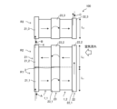
- FIG. 3 is a diagram showing the flow state of refrigerant in the heat exchanger 100 according to the first embodiment.
- FIG. 3 shows the flow state of the refrigerant when the refrigerant that has flowed into the first header 21 flows out from the second header 22.
- arrows indicate the flow of refrigerant
- white arrows indicate the direction of air flow.
- the leeward heat exchange row 1_1 and the upwind heat exchange row 1_2 have a first region R1, a second region R2, and a third region R3.
- the first region R1 is a region where the refrigerant that has flowed into the first header 21 flows in the opposite direction to the air flow direction and flows into the second header 22.
- the second region R2 is a region where the refrigerant that has passed through the first region R1 and entered the second header 22 flows in parallel to the air flow direction and flows into the first header 21.
- the third region R3 is a region where the refrigerant that has passed through the second region R2 and entered the first header 21 flows in the opposite direction to the air flow direction and flows into the second header 22.
- the first header 21 includes a first header 21_1 of the first region R1, a first header 21_2 of the second region R2, and a first header 21_3 of the third region R3.
- the second header 22 includes a second header 22_1 of the first region R1, a second header 22_2 of the second region R2, and a second header 22_3 of the third region R3.
- the common header 23 includes a common header 23_1 for the first region R1, a common header 23_2 for the second region R2, and a common header 23_3 for the third region R3.
- FIG. 3 shows a case where the first header 21, second header 22, and common header 23 are divided into three parts, they do not need to be divided into three parts.
- the interior of one header may be partitioned into a plurality of regions by a partition plate provided inside one header.
- the first region R1, the second region R2, and the third region R3 are connected in series by a connecting pipe 4.
- the second header 22_1 is connected in series to the second header 22_2 via the connecting pipe 4.
- the first header 21_2 is connected in series to the first header 21_3 via the connecting pipe 4.
- first region R1, the second region R2, and the third region R3 may be separated by partition plates in the first header 21, the second header 22, and the common header 23.
- the length of the leeward heat exchange section 100_1 in the longitudinal direction of the first header 21_1 in the first region R1 and the length of the upwind heat exchange section 100_2 in the longitudinal direction of the second header 22_1 in the first region R1 are L.
- L2 be the length of the leeward heat exchange section 100_1 in the longitudinal direction of the first header 21_2 in the second region R2 and the length of the upwind heat exchange section 100_2 in the longitudinal direction of the second header 22_2 in the second region R2.
- L3 be the length of the leeward heat exchange section 100_1 in the longitudinal direction of the first header 21_3 in the third region R3 and the length of the upwind heat exchange section 100_2 in the longitudinal direction of the second header 22_3 in the third region R3.
- points A, B, and C correspond to points A, B, and C in FIG. 4, which will be described later.
- FIG. 4 is a diagram showing the state of the refrigerant flowing into the heat exchanger 100 according to the first embodiment.
- the vertical axis represents temperature T
- the horizontal axis represents entropy S.
- arrows indicate the direction of change in refrigerant when the heat exchanger 100 functions as a condenser.
- the refrigerant first flows into the heat exchanger 100 in a superheated gas state, passes through a gas-liquid two-phase state, and then becomes a supercooled liquid state and exits.
- a region where the refrigerant is a superheated gas is designated as a region X
- a region where the refrigerant is in a gas-liquid two-phase state is designated as a region Y
- a region where the refrigerant is in a supercooled liquid state is designated as a region Z.
- L 1 , L 2 and L 3 shown in FIG. 3 are the states of the refrigerant at points A, B and C shown in FIG. determined to be realized.
- point A indicates the temperature T and entropy S immediately before the refrigerant flows into region X.
- Point B indicates the temperature T and entropy S immediately before the refrigerant leaves the region Y and flows into the third region R3.
- Point C indicates the temperature T and entropy S of the refrigerant immediately after it flows out of the region Z.
- the heat exchanger 100 of Embodiment 1 configures L 1 , L 2 , and L 3 so that the flow of the refrigerant is opposite to the air flow direction in the region X and the region Y where the temperature of the refrigerant changes.
- Region X and region Z are sensible heat regions.
- the sensible heat region is a region where the temperature of the refrigerant changes as the heat exchanger 100 exchanges heat.
- Region Y is a latent heat region in which the temperature of the refrigerant does not change even if heat exchange is performed in the heat exchanger 100.
- the refrigerant flowing in the first region R1 contains superheated gas
- the refrigerant flowing in the second region R2 is a gas-liquid two-phase refrigerant
- the refrigerant flowing in the third region R3 contains supercooled liquid.
- the temperature also changes in the second region R2 where the gas-liquid two-phase refrigerant flows even when the heat exchanger 100 functions as an evaporator.
- a gas-liquid two-phase refrigerant flows into the refrigerant, passes through the evaporator, and becomes a single-phase gas.
- the heat exchanger 100 functions as an evaporator using a variable path or the like, it is configured so that the refrigerant flows in counterflow, parallel flow, or counterflow with respect to the air flow direction, as in the case of a condenser. It's okay. This also makes it possible to improve the evaporation performance of the heat exchanger 100.
- the heat exchanger 100 when the heat exchanger 100 functions as a condenser, refrigerant and air are mixed not only in the third region R3, which is a supercooled liquid region, but also in the first region R1, which is a superheated gas region, unlike the conventional case. It is possible to provide a heat exchanger 100 in which the flow directions are opposite. Furthermore, in the second region R2, which is a latent heat region where heat can be sufficiently exchanged even with a small temperature difference, the refrigerant in a gas-liquid two-phase state is caused to flow parallel to the air flow direction.
- the refrigerant is allowed to flow in opposite directions with respect to the air flow direction in the supercooled liquid state and the superheated gas state, which are sensible heat regions that require a large temperature difference. This improves the heat exchange performance of the heat exchanger 100.
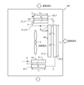
- FIG. 5 is a diagram showing the flow state of the refrigerant in the heat exchanger 100 of the air conditioner 300 according to the second embodiment.
- FIG. 5 shows the flow state of the refrigerant when the refrigerant that has flowed into the first header 21 flows out from the second header 22.
- arrows indicate the flow of refrigerant
- white arrows indicate the direction of air flow.
- FIG. 6 is a diagram showing the arrangement of the first header 21 and the second header 22 of the heat exchanger 100 in the air conditioner 300 according to the second embodiment.
- the common header 23 and the heat exchanger tubes 1 shown in FIG. 5 are omitted and not shown.
- arrows indicate the flow of refrigerant
- white arrows indicate the direction of air flow.
- Embodiment 2 shows a heat exchanger 100 having two heat exchangers, a first heat exchanger 11 and a second heat exchanger 12, as an example of a heat exchanger 100 having three regions.
- the outdoor unit housing 7 houses the fan 5, the compressor 6, the first heat exchanger 11, and the second heat exchanger 12.
- the outdoor unit housing 7 is a side flow type housing with a rectangular planar shape.
- the compressor 6 compresses the refrigerant and discharges high-pressure gas refrigerant.
- the fan 5 blows air for heat exchange to the first heat exchanger 11 and the second heat exchanger 12.
- the first heat exchanger 11 and the second heat exchanger 12 are arranged in an L-shape so as to surround the fan 5.
- the first heat exchanger 11 has a first region R1 and a second region R2.
- the second heat exchanger 12 has a third region R3.
- the first heat exchanger 11 has a first header 21_1 in a first region R1 and a first header 21_2 in a second region R2.
- a partition plate 3 that partitions the first region R1 and the second region R2 is provided between the first header 21_1 and the first header 21_2.
- the first heat exchanger 11 has a common header 23_1 in the first region R1 and a common header 23_2 in the second region R2.
- a partition plate 3 that partitions the first region R1 and the second region R2 is provided between the common header 23_1 and the common header 23_2.
- the second heat exchanger 12 has a third region R3.
- the second heat exchanger 12 includes a first header 21_3 in the third region R3, a second header 22_3 in the third region R3, and a common header 23_3 in the third region R3.
- the third region R3 is a region where the supercooled liquid flows, and if the length L3 of the heat exchange section in the longitudinal direction of the third region R3 is set too large, there is a possibility that the refrigerant of the superheated gas will flow into the second region R2. be.
- the effect of improving heat exchange performance is reduced by causing the refrigerant to flow in the first region R1 in a direction opposite to the air flow direction.
- the area into which the superheated gas and the gas-liquid two-phase refrigerant, which have a greater pressure loss than the refrigerant in the supercooled liquid state, flow into becomes smaller, resulting in an increase in pressure loss and a decrease in heat exchange performance.
- the length in the longitudinal direction of the first region R1 is L 1
- the length in the longitudinal direction of the second region R2 is L 2
- the length in the longitudinal direction of the third region R3 is L 3 , (L 1 +L 2 )/2>L 3 .
- the sum of the length L1 of the heat exchange part in the longitudinal direction of the first region R1 of the first heat exchanger 11 and the length L2 of the heat exchange part in the longitudinal direction of the second region R2 is 2 longer than the length L 3 of the heat exchange section in the longitudinal direction of the third region R 3 of the heat exchanger 12 .
- L 2 >L 1 .
- the first header 21_1 has a refrigerant inlet 21_1_A into which the refrigerant flows.
- the first header 21_2 has a refrigerant outlet 21_2_B through which the refrigerant that has flowed in from the refrigerant inlet 21_1_A flows out.
- the first header 21_3 has a refrigerant inlet 21_3_A into which the refrigerant flowing out from the refrigerant outlet 21_2_B flows.
- the second header 22_3 has a refrigerant outlet 22_3_B through which the refrigerant flows out.
- the refrigerant outlet 21_2_B and the refrigerant inlet 22_3_A are connected by a connecting pipe 4.
- the refrigerant inlet 21_3_A is provided at the end of the first header 21_3 in the third region R3 on the far side from the refrigerant outlet 21_2_B.
- the refrigerant that has flowed into the first heat exchanger 11 from the refrigerant inlet 21_1_A of the first header 21_1 first flows through the first region R1 so as to be opposed to the air flow direction.
- the refrigerant that has flowed through the first region R1 flows into the second header 22 of the first region R1, and flows through the second region R2 in parallel to the air flow direction.
- the refrigerant that has flowed through the second region R2 flows into the first header 21_2 and flows out from the refrigerant outlet 21_2_B.
- the refrigerant flowing out from the refrigerant outlet 21_2_B then flows into the refrigerant inlet 21_3_A of the first header 21_3 in the third region R3 of the second heat exchanger 12 through the connection pipe 4.
- the refrigerant that has flowed into the refrigerant inlet 21_3_A flows through the third region R3 opposite to the air flow direction and flows out from the second heat exchanger 12.
- heat exchanger 100 of Embodiment 2 is applied to other than side flow casings.
- a plurality of heat exchangers 100 may be arranged on four sides surrounding the fan 5 in a top-flow outdoor unit casing 7 that blows air sucked in from the sides of the casing from the top of the casing.
- FIG. 7 is a diagram showing a state in which two heat exchangers 100_A and 100_B according to the second embodiment are arranged on four sides in the outdoor unit casing 7 so as to surround the fan 5.
- the common header 23 and heat exchanger tubes 1 shown in FIG. 5 are omitted and not shown.
- arrows indicate the flow of refrigerant
- white arrows indicate the direction of air flow.
- FIG. 7 it has two heat exchangers 100_A and 100_B, each having a first heat exchanger 11 and a second heat exchanger 12. Heat exchanger 100_A and heat exchanger 100_B are arranged to surround fan 5.
- first heat exchanger 11 and the second heat exchanger 12 of the heat exchanger 100_A are arranged in an L-shape so as to surround the fan 5.
- the first heat exchanger 11 and the second heat exchanger 12 of the heat exchanger 100_B are arranged in an L shape so as to surround the fan 5.
- the first heat exchanger 11 includes the first region R1 and the second region R2. That is, as an example of a method of switching the flow of refrigerant with respect to the air flowing into the heat exchanger 100 from opposing to parallel, a method of providing a partition plate 3 that divides the internal space of the first header 21 is adopted. Therefore, the influence on the structure of the heat exchanger 100 can be minimized, the refrigerant flow can be switched, and manufacturing costs can be suppressed.
- the heat exchanger 100 having the first heat exchanger 11 and the second heat exchanger 12 is mounted without changing the size of the casing, the heat exchanger 100 will not be able to transfer due to structural constraints such as piping. The thermal area will have to be reduced. As a result, the mounting area of the heat exchanger 100 becomes smaller and the heat exchange performance deteriorates.
- the refrigerant outlet 21_2_B and the refrigerant inlet 21_3_A are connected by the connection pipe 4.
- the refrigerant inlet 21_3_A is provided at the end of the first header 21_3 in the third region R3 far from the refrigerant outlet 21_2_B.
- the heat exchange area between the first heat exchanger 11 and the second heat exchanger 12 can be maximized and the mounting area of the heat exchanger 100 can be increased, so that improvement in heat exchange performance is expected.
- the ability of the heat exchanger 100 can be maximized.
- FIG. 8 is a diagram showing a state in which the heat exchanger 100 according to the third embodiment is arranged inside the outdoor unit housing 7. As shown in FIG. The outdoor unit casing 7 is a top flow type casing. In FIG. 8, the common header 23 shown in FIG. 5 is omitted and not shown. In FIG. 8, arrows indicate the flow of refrigerant, and white arrows indicate the direction of air flow.
- the heat exchanger 100 includes a first heat exchanger 11, a second heat exchanger 12, and a third heat exchanger 13.
- the first heat exchanger 11, the second heat exchanger 12, and the third heat exchanger 13 are arranged in a U-shape so as to surround the fan 5.
- the first heat exchanger 11 has a first region R1, and the refrigerant flows in a counterflow to the air flow direction.
- the second heat exchanger 12 has a second region R2, and the refrigerant flows in parallel to the air flow direction.
- the third heat exchanger 13 has a third region R3, and the refrigerant flows in a counterflow to the air flow direction.
- the second header 22_1 of the first region R1 on the windward side of the first heat exchanger 11 is connected to the second header 22_2 of the second region R2 on the windward side of the second heat exchanger 12 via the connection pipe 4.
- the first header 21_2 in the second region R2 on the leeward side of the second heat exchanger 12 is connected to the first header 21_3 in the third region R3 on the leeward side of the third heat exchanger 13 via the connecting pipe 4.
- connection between the first heat exchanger 11 and the second heat exchanger 12 is realized by connecting the outer second header 22_1 to the outer second header 22_2 by the connection pipe 4.
- connection between the second heat exchanger 12 and the third heat exchanger 13 is realized by connecting the inner first header 21_2 to the inner first header 21_3 by the connection pipe 4.
- the refrigerant inlet 21_3_A is provided at the end of the first header 21_3 in the third region R3 far from the refrigerant outlet 21_2_B. Therefore, according to the heat exchanger 100 of the third embodiment, the space of the heat exchanger 100 can be saved, and it is expected that the heat exchange performance will be improved and the mounting area will be maximized.
Landscapes
- Engineering & Computer Science (AREA)
- Physics & Mathematics (AREA)
- Mechanical Engineering (AREA)
- Thermal Sciences (AREA)
- General Engineering & Computer Science (AREA)
- Heat-Exchange Devices With Radiators And Conduit Assemblies (AREA)
Priority Applications (6)
| Application Number | Priority Date | Filing Date | Title |
|---|---|---|---|
| CN202280096466.9A CN119278350A (zh) | 2022-06-01 | 2022-06-01 | 热交换器及制冷循环装置 |
| US18/868,188 US20250327603A1 (en) | 2022-06-01 | 2022-06-01 | Heat exchanger and refrigeration cycle apparatus |
| GB2416173.9A GB2632959A (en) | 2022-06-01 | 2022-06-01 | Heat exchanger, and refrigeration cycle device |
| DE112022007322.5T DE112022007322T5 (de) | 2022-06-01 | 2022-06-01 | Wärmetauscher und Kühlkreislaufvorrichtung |
| JP2024524064A JP7738754B2 (ja) | 2022-06-01 | 2022-06-01 | 熱交換器及び冷凍サイクル装置 |
| PCT/JP2022/022283 WO2023233572A1 (ja) | 2022-06-01 | 2022-06-01 | 熱交換器及び冷凍サイクル装置 |
Applications Claiming Priority (1)
| Application Number | Priority Date | Filing Date | Title |
|---|---|---|---|
| PCT/JP2022/022283 WO2023233572A1 (ja) | 2022-06-01 | 2022-06-01 | 熱交換器及び冷凍サイクル装置 |
Publications (1)
| Publication Number | Publication Date |
|---|---|
| WO2023233572A1 true WO2023233572A1 (ja) | 2023-12-07 |
Family
ID=89026051
Family Applications (1)
| Application Number | Title | Priority Date | Filing Date |
|---|---|---|---|
| PCT/JP2022/022283 Ceased WO2023233572A1 (ja) | 2022-06-01 | 2022-06-01 | 熱交換器及び冷凍サイクル装置 |
Country Status (6)
| Country | Link |
|---|---|
| US (1) | US20250327603A1 (https=) |
| JP (1) | JP7738754B2 (https=) |
| CN (1) | CN119278350A (https=) |
| DE (1) | DE112022007322T5 (https=) |
| GB (1) | GB2632959A (https=) |
| WO (1) | WO2023233572A1 (https=) |
Citations (5)
| Publication number | Priority date | Publication date | Assignee | Title |
|---|---|---|---|---|
| JP2012149845A (ja) * | 2011-01-20 | 2012-08-09 | Mitsubishi Electric Corp | 空気調和装置のユニット及び空気調和装置 |
| WO2019239446A1 (ja) * | 2018-06-11 | 2019-12-19 | 三菱電機株式会社 | 空気調和装置の室外機及び空気調和装置 |
| WO2021234953A1 (ja) * | 2020-05-22 | 2021-11-25 | 三菱電機株式会社 | 熱交換器、熱交換器を備えた室外機、および、室外機を備えた空気調和装置 |
| WO2021234956A1 (ja) * | 2020-05-22 | 2021-11-25 | 三菱電機株式会社 | 熱交換器、室外機および冷凍サイクル装置 |
| WO2021234961A1 (ja) * | 2020-05-22 | 2021-11-25 | 三菱電機株式会社 | 熱交換器、空気調和装置の室外機及び空気調和装置 |
Family Cites Families (1)
| Publication number | Priority date | Publication date | Assignee | Title |
|---|---|---|---|---|
| WO2021245877A1 (ja) * | 2020-06-04 | 2021-12-09 | 三菱電機株式会社 | 熱交換器および冷凍サイクル装置 |
-
2022
- 2022-06-01 DE DE112022007322.5T patent/DE112022007322T5/de active Pending
- 2022-06-01 WO PCT/JP2022/022283 patent/WO2023233572A1/ja not_active Ceased
- 2022-06-01 GB GB2416173.9A patent/GB2632959A/en active Pending
- 2022-06-01 US US18/868,188 patent/US20250327603A1/en active Pending
- 2022-06-01 JP JP2024524064A patent/JP7738754B2/ja active Active
- 2022-06-01 CN CN202280096466.9A patent/CN119278350A/zh active Pending
Patent Citations (5)
| Publication number | Priority date | Publication date | Assignee | Title |
|---|---|---|---|---|
| JP2012149845A (ja) * | 2011-01-20 | 2012-08-09 | Mitsubishi Electric Corp | 空気調和装置のユニット及び空気調和装置 |
| WO2019239446A1 (ja) * | 2018-06-11 | 2019-12-19 | 三菱電機株式会社 | 空気調和装置の室外機及び空気調和装置 |
| WO2021234953A1 (ja) * | 2020-05-22 | 2021-11-25 | 三菱電機株式会社 | 熱交換器、熱交換器を備えた室外機、および、室外機を備えた空気調和装置 |
| WO2021234956A1 (ja) * | 2020-05-22 | 2021-11-25 | 三菱電機株式会社 | 熱交換器、室外機および冷凍サイクル装置 |
| WO2021234961A1 (ja) * | 2020-05-22 | 2021-11-25 | 三菱電機株式会社 | 熱交換器、空気調和装置の室外機及び空気調和装置 |
Also Published As
| Publication number | Publication date |
|---|---|
| JP7738754B2 (ja) | 2025-09-12 |
| DE112022007322T5 (de) | 2025-03-27 |
| GB202416173D0 (en) | 2024-12-18 |
| JPWO2023233572A1 (https=) | 2023-12-07 |
| GB2632959A (en) | 2025-02-26 |
| CN119278350A (zh) | 2025-01-07 |
| US20250327603A1 (en) | 2025-10-23 |
Similar Documents
| Publication | Publication Date | Title |
|---|---|---|
| CN112204312B (zh) | 空气调节装置的室外机及空气调节装置 | |
| US9651317B2 (en) | Heat exchanger and air conditioner | |
| AU740183B2 (en) | Heat exchanger | |
| US8205470B2 (en) | Indoor unit for air conditioner | |
| JP4827882B2 (ja) | 熱交換器モジュール、熱交換器、室内ユニット及び空調冷凍装置、並びに熱交換器の製造方法 | |
| US20160223231A1 (en) | Heat exchanger and air conditioner | |
| WO2013160957A1 (ja) | 熱交換器、室内機及び冷凍サイクル装置 | |
| WO2007017969A1 (ja) | 空気調和機及び空気調和機の製造方法 | |
| JPWO2019239445A1 (ja) | 冷媒分配器、熱交換器及び空気調和装置 | |
| JP2019215161A (ja) | 空気調和装置の室外機及び空気調和装置 | |
| JP6533257B2 (ja) | 空気調和機 | |
| WO2018180932A1 (ja) | 熱交換器又は冷凍装置 | |
| WO2021245877A1 (ja) | 熱交換器および冷凍サイクル装置 | |
| JP7738754B2 (ja) | 熱交換器及び冷凍サイクル装置 | |
| JP6590957B2 (ja) | 冷凍装置 | |
| CN111512099B (zh) | 热交换器及制冷循环装置 | |
| JP7693095B2 (ja) | 空気調和装置の室外機および空気調和装置 | |
| JP7374321B2 (ja) | 空気調和装置の室外機 | |
| WO2021234961A1 (ja) | 熱交換器、空気調和装置の室外機及び空気調和装置 | |
| TWI810896B (zh) | 除濕裝置 | |
| JP7682378B2 (ja) | 室外機およびそれを備えた空気調和装置 | |
| JPWO2019155571A1 (ja) | 熱交換器および冷凍サイクル装置 | |
| WO2025181955A1 (ja) | 空気調和装置の室外機、および空気調和装置 | |
| JP7566155B2 (ja) | 熱交換器及び空気調和装置 | |
| KR200168000Y1 (ko) | 룸 에어컨용 증발기 |
Legal Events
| Date | Code | Title | Description |
|---|---|---|---|
| 121 | Ep: the epo has been informed by wipo that ep was designated in this application |
Ref document number: 22944859 Country of ref document: EP Kind code of ref document: A1 |
|
| ENP | Entry into the national phase |
Ref document number: 2024524064 Country of ref document: JP Kind code of ref document: A |
|
| ENP | Entry into the national phase |
Ref document number: 202416173 Country of ref document: GB Kind code of ref document: A Free format text: PCT FILING DATE = 20220601 |
|
| WWE | Wipo information: entry into national phase |
Ref document number: 2416173.9 Country of ref document: GB |
|
| WWE | Wipo information: entry into national phase |
Ref document number: 18868188 Country of ref document: US |
|
| WWE | Wipo information: entry into national phase |
Ref document number: 202280096466.9 Country of ref document: CN |
|
| WWE | Wipo information: entry into national phase |
Ref document number: 112022007322 Country of ref document: DE |
|
| WWP | Wipo information: published in national office |
Ref document number: 202280096466.9 Country of ref document: CN |
|
| WWP | Wipo information: published in national office |
Ref document number: 2416173.9 Country of ref document: GB |
|
| WWP | Wipo information: published in national office |
Ref document number: 112022007322 Country of ref document: DE |
|
| 122 | Ep: pct application non-entry in european phase |
Ref document number: 22944859 Country of ref document: EP Kind code of ref document: A1 |
|
| WWP | Wipo information: published in national office |
Ref document number: 18868188 Country of ref document: US |