WO2023233493A1 - メタン生成システム - Google Patents
メタン生成システム Download PDFInfo
- Publication number
- WO2023233493A1 WO2023233493A1 PCT/JP2022/022025 JP2022022025W WO2023233493A1 WO 2023233493 A1 WO2023233493 A1 WO 2023233493A1 JP 2022022025 W JP2022022025 W JP 2022022025W WO 2023233493 A1 WO2023233493 A1 WO 2023233493A1
- Authority
- WO
- WIPO (PCT)
- Prior art keywords
- gas
- methane
- carbon dioxide
- auxiliary
- production system
- Prior art date
- Legal status (The legal status is an assumption and is not a legal conclusion. Google has not performed a legal analysis and makes no representation as to the accuracy of the status listed.)
- Ceased
Links
Images


Classifications
-
- C—CHEMISTRY; METALLURGY
- C10—PETROLEUM, GAS OR COKE INDUSTRIES; TECHNICAL GASES CONTAINING CARBON MONOXIDE; FUELS; LUBRICANTS; PEAT
- C10L—FUELS NOT OTHERWISE PROVIDED FOR; NATURAL GAS; SYNTHETIC NATURAL GAS OBTAINED BY PROCESSES NOT COVERED BY SUBCLASSES C10G OR C10K; LIQUIFIED PETROLEUM GAS; USE OF ADDITIVES TO FUELS OR FIRES; FIRE-LIGHTERS
- C10L3/00—Gaseous fuels; Natural gas; Synthetic natural gas obtained by processes not covered by subclass C10G, C10K; Liquefied petroleum gas
- C10L3/06—Natural gas; Synthetic natural gas obtained by processes not covered by C10G, C10K3/02 or C10K3/04
- C10L3/08—Production of synthetic natural gas
-
- H—ELECTRICITY
- H01—ELECTRIC ELEMENTS
- H01M—PROCESSES OR MEANS, e.g. BATTERIES, FOR THE DIRECT CONVERSION OF CHEMICAL ENERGY INTO ELECTRICAL ENERGY
- H01M8/00—Fuel cells; Manufacture thereof
- H01M8/06—Combination of fuel cells with means for production of reactants or for treatment of residues
- H01M8/0606—Combination of fuel cells with means for production of reactants or for treatment of residues with means for production of gaseous reactants
- H01M8/0656—Combination of fuel cells with means for production of reactants or for treatment of residues with means for production of gaseous reactants by electrochemical means
-
- B—PERFORMING OPERATIONS; TRANSPORTING
- B01—PHYSICAL OR CHEMICAL PROCESSES OR APPARATUS IN GENERAL
- B01J—CHEMICAL OR PHYSICAL PROCESSES, e.g. CATALYSIS OR COLLOID CHEMISTRY; THEIR RELEVANT APPARATUS
- B01J19/00—Chemical, physical or physico-chemical processes in general; Their relevant apparatus
- B01J19/24—Stationary reactors without moving elements inside
- B01J19/245—Stationary reactors without moving elements inside placed in series
-
- C—CHEMISTRY; METALLURGY
- C01—INORGANIC CHEMISTRY
- C01B—NON-METALLIC ELEMENTS; COMPOUNDS THEREOF; METALLOIDS OR COMPOUNDS THEREOF NOT COVERED BY SUBCLASS C01C
- C01B3/00—Hydrogen; Gaseous mixtures containing hydrogen; Separation of hydrogen from mixtures containing it; Purification of hydrogen; Reversible storage of hydrogen
- C01B3/02—Production of hydrogen; Production of gaseous mixtures containing hydrogen
-
- C—CHEMISTRY; METALLURGY
- C01—INORGANIC CHEMISTRY
- C01B—NON-METALLIC ELEMENTS; COMPOUNDS THEREOF; METALLOIDS OR COMPOUNDS THEREOF NOT COVERED BY SUBCLASS C01C
- C01B3/00—Hydrogen; Gaseous mixtures containing hydrogen; Separation of hydrogen from mixtures containing it; Purification of hydrogen; Reversible storage of hydrogen
- C01B3/02—Production of hydrogen; Production of gaseous mixtures containing hydrogen
- C01B3/32—Production of hydrogen; Production of gaseous mixtures containing hydrogen by reaction of gaseous or liquid organic compounds with gasifying agents, e.g. water, carbon dioxide or air
- C01B3/34—Production of hydrogen; Production of gaseous mixtures containing hydrogen by reaction of gaseous or liquid organic compounds with gasifying agents, e.g. water, carbon dioxide or air by reaction of hydrocarbons with gasifying agents
- C01B3/38—Production of hydrogen; Production of gaseous mixtures containing hydrogen by reaction of gaseous or liquid organic compounds with gasifying agents, e.g. water, carbon dioxide or air by reaction of hydrocarbons with gasifying agents using catalysts
-
- C—CHEMISTRY; METALLURGY
- C25—ELECTROLYTIC OR ELECTROPHORETIC PROCESSES; APPARATUS THEREFOR
- C25B—ELECTROLYTIC OR ELECTROPHORETIC PROCESSES FOR THE PRODUCTION OF COMPOUNDS OR NON-METALS; APPARATUS THEREFOR
- C25B1/00—Electrolytic production of inorganic compounds or non-metals
- C25B1/01—Products
- C25B1/02—Hydrogen or oxygen
- C25B1/04—Hydrogen or oxygen by electrolysis of water
- C25B1/042—Hydrogen or oxygen by electrolysis of water by electrolysis of steam
-
- C—CHEMISTRY; METALLURGY
- C25—ELECTROLYTIC OR ELECTROPHORETIC PROCESSES; APPARATUS THEREFOR
- C25B—ELECTROLYTIC OR ELECTROPHORETIC PROCESSES FOR THE PRODUCTION OF COMPOUNDS OR NON-METALS; APPARATUS THEREFOR
- C25B15/00—Operating or servicing cells
- C25B15/02—Process control or regulation
- C25B15/021—Process control or regulation of heating or cooling
-
- C—CHEMISTRY; METALLURGY
- C25—ELECTROLYTIC OR ELECTROPHORETIC PROCESSES; APPARATUS THEREFOR
- C25B—ELECTROLYTIC OR ELECTROPHORETIC PROCESSES FOR THE PRODUCTION OF COMPOUNDS OR NON-METALS; APPARATUS THEREFOR
- C25B15/00—Operating or servicing cells
- C25B15/08—Supplying or removing reactants or electrolytes; Regeneration of electrolytes
- C25B15/081—Supplying products to non-electrochemical reactors that are combined with the electrochemical cell, e.g. Sabatier reactor
-
- H—ELECTRICITY
- H01—ELECTRIC ELEMENTS
- H01M—PROCESSES OR MEANS, e.g. BATTERIES, FOR THE DIRECT CONVERSION OF CHEMICAL ENERGY INTO ELECTRICAL ENERGY
- H01M8/00—Fuel cells; Manufacture thereof
- H01M8/04—Auxiliary arrangements, e.g. for control of pressure or for circulation of fluids
- H01M8/04007—Auxiliary arrangements, e.g. for control of pressure or for circulation of fluids related to heat exchange
- H01M8/04014—Heat exchange using gaseous fluids; Heat exchange by combustion of reactants
-
- H—ELECTRICITY
- H01—ELECTRIC ELEMENTS
- H01M—PROCESSES OR MEANS, e.g. BATTERIES, FOR THE DIRECT CONVERSION OF CHEMICAL ENERGY INTO ELECTRICAL ENERGY
- H01M8/00—Fuel cells; Manufacture thereof
- H01M8/06—Combination of fuel cells with means for production of reactants or for treatment of residues
- H01M8/0606—Combination of fuel cells with means for production of reactants or for treatment of residues with means for production of gaseous reactants
- H01M8/0612—Combination of fuel cells with means for production of reactants or for treatment of residues with means for production of gaseous reactants from carbon-containing material
- H01M8/0618—Reforming processes, e.g. autothermal, partial oxidation or steam reforming
-
- H—ELECTRICITY
- H01—ELECTRIC ELEMENTS
- H01M—PROCESSES OR MEANS, e.g. BATTERIES, FOR THE DIRECT CONVERSION OF CHEMICAL ENERGY INTO ELECTRICAL ENERGY
- H01M8/00—Fuel cells; Manufacture thereof
- H01M8/06—Combination of fuel cells with means for production of reactants or for treatment of residues
- H01M8/0662—Treatment of gaseous reactants or gaseous residues, e.g. cleaning
- H01M8/0668—Removal of carbon monoxide or carbon dioxide
-
- C—CHEMISTRY; METALLURGY
- C01—INORGANIC CHEMISTRY
- C01B—NON-METALLIC ELEMENTS; COMPOUNDS THEREOF; METALLOIDS OR COMPOUNDS THEREOF NOT COVERED BY SUBCLASS C01C
- C01B2203/00—Integrated processes for the production of hydrogen or synthesis gas
- C01B2203/02—Processes for making hydrogen or synthesis gas
- C01B2203/0205—Processes for making hydrogen or synthesis gas containing a reforming step
- C01B2203/0227—Processes for making hydrogen or synthesis gas containing a reforming step containing a catalytic reforming step
- C01B2203/0233—Processes for making hydrogen or synthesis gas containing a reforming step containing a catalytic reforming step the reforming step being a steam reforming step
-
- C—CHEMISTRY; METALLURGY
- C01—INORGANIC CHEMISTRY
- C01B—NON-METALLIC ELEMENTS; COMPOUNDS THEREOF; METALLOIDS OR COMPOUNDS THEREOF NOT COVERED BY SUBCLASS C01C
- C01B2203/00—Integrated processes for the production of hydrogen or synthesis gas
- C01B2203/06—Integration with other chemical processes
- C01B2203/066—Integration with other chemical processes with fuel cells
-
- C—CHEMISTRY; METALLURGY
- C25—ELECTROLYTIC OR ELECTROPHORETIC PROCESSES; APPARATUS THEREFOR
- C25B—ELECTROLYTIC OR ELECTROPHORETIC PROCESSES FOR THE PRODUCTION OF COMPOUNDS OR NON-METALS; APPARATUS THEREFOR
- C25B1/00—Electrolytic production of inorganic compounds or non-metals
- C25B1/01—Products
- C25B1/02—Hydrogen or oxygen
- C25B1/04—Hydrogen or oxygen by electrolysis of water
-
- C—CHEMISTRY; METALLURGY
- C25—ELECTROLYTIC OR ELECTROPHORETIC PROCESSES; APPARATUS THEREFOR
- C25B—ELECTROLYTIC OR ELECTROPHORETIC PROCESSES FOR THE PRODUCTION OF COMPOUNDS OR NON-METALS; APPARATUS THEREFOR
- C25B1/00—Electrolytic production of inorganic compounds or non-metals
- C25B1/01—Products
- C25B1/23—Carbon monoxide or syngas
-
- Y—GENERAL TAGGING OF NEW TECHNOLOGICAL DEVELOPMENTS; GENERAL TAGGING OF CROSS-SECTIONAL TECHNOLOGIES SPANNING OVER SEVERAL SECTIONS OF THE IPC; TECHNICAL SUBJECTS COVERED BY FORMER USPC CROSS-REFERENCE ART COLLECTIONS [XRACs] AND DIGESTS
- Y02—TECHNOLOGIES OR APPLICATIONS FOR MITIGATION OR ADAPTATION AGAINST CLIMATE CHANGE
- Y02E—REDUCTION OF GREENHOUSE GAS [GHG] EMISSIONS, RELATED TO ENERGY GENERATION, TRANSMISSION OR DISTRIBUTION
- Y02E60/00—Enabling technologies; Technologies with a potential or indirect contribution to GHG emissions mitigation
- Y02E60/30—Hydrogen technology
- Y02E60/50—Fuel cells
Definitions
- the present disclosure relates to methane production systems.
- Patent Document 1 discloses an apparatus for producing methane using carbon dioxide and water. This device reduces water and carbon dioxide to obtain synthesis gas containing hydrogen and carbon monoxide. This device produces methane from synthesis gas.
- the present disclosure aims to provide a methane generation system that can increase methane generation efficiency.
- One embodiment of the methane production system includes an electrolysis device that electrolyzes water to produce hydrogen, and a methane reactor that produces a fuel gas containing methane through a methanation reaction using the hydrogen.
- a generating section a reformer that reformes the fuel gas to obtain a reformed gas, a fuel cell that generates power by a reaction that obtains a product gas from the reformed gas and an oxygen-containing gas, and the product gas.
- a recovery device that separates recovered gas containing carbon dioxide from a return fluid that is a part of the methane generator, and a circulation path that guides the recovered gas to the methane generating section.
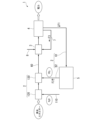
- FIG. 1 is a schematic diagram of a methane generation system according to Embodiment 1.
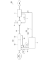
- FIG. 2 is a schematic diagram of a methane generation system according to a second embodiment.
- FIG. 3 is a schematic diagram of a methane generation system according to Embodiment 3.
- FIG. 3 is a schematic diagram of a part of a methane generation system according to Embodiment 4.
- FIG. 3 is a schematic diagram of a part of a methane generation system according to Embodiment 5.
- FIG. FIG. 3 is a schematic diagram of a methane generation system according to a sixth embodiment.
- FIG. 7 is a schematic diagram of a methane generation system according to Embodiment 7.
- FIG. 1 is a schematic diagram showing a methane generation system in Embodiment 1.
- the methane generation system 1 includes a methane generation section 2, a reformer 3, a fuel cell 4, a recovery device 5, a circulation path 6, and a return path 7.
- the methane generation system is also referred to as a "fuel cell system.”
- the methane generation unit 2 includes a supply path 110, an electrolyzer 120, and a methane reactor 130.
- the supply path 110 guides water (steam) supplied from a supply source (not shown) to the electrolyzer 120.
- the supply path 110 may be provided with an evaporator (steam generator) that vaporizes water.
- the electrolyzer 120 electrolyzes water (H 2 O) to obtain a mixed gas containing hydrogen (H 2 ) and oxygen (O 2 ). Electrolysis proceeds, for example, according to formula (I) shown below. 2H 2 O ⁇ 2H 2 +O 2 ...(I)
- electrolysis can be performed using electric power generated using renewable energy (for example, solar power generation, wind power generation, etc.).
- renewable energy for example, solar power generation, wind power generation, etc.
- Methane obtained using renewable energy can be considered a carbon-neutral fuel that does not contribute to global warming, as no additional carbon dioxide is generated when it is combusted.
- the methane reactor 130 converts carbon dioxide (CO 2 ) supplied from the circulation path 6 and hydrogen (H 2 ) from the electrolyzer 120 into methane (CH 4 ) and water (H 2 O) through a methanation reaction. ) is obtained.
- the methanation reaction proceeds, for example, according to formula (II) shown below. CO 2 +4H 2 ⁇ CH 4 +2H 2 O...(II)
- the methane reactor 130 is preferably equipped with a methanation catalyst with which the mixed gas comes into contact.
- methanation catalysts include Ni catalysts and Ru catalysts. Methanation catalysts promote methanation reactions.
- the fuel gas obtained in the methane reactor 130 includes not only methane and water but also unreacted carbon dioxide, hydrogen (H 2 ), and the like.
- the fuel gas is guided to the reformer 3 through the exhaust path 60.
- the water contained in the fuel gas guided to the reformer 3 is desirably water vapor.
- the reformer 3 obtains a reformed gas containing carbon monoxide (CO) and hydrogen (H 2 ) from methane and water (steam) contained in the fuel gas through a reforming reaction.
- the modification reaction proceeds, for example, according to formula (III) shown below. CH4 + H2O ⁇ CO+ 3H2 ...(III)
- the reformer 3 includes a reforming catalyst with which the fuel gas comes into contact.
- the reforming catalyst include Ni catalyst and Ru catalyst.
- a reforming catalyst accelerates the reforming reaction.
- the reformer 3 includes a carbon monoxide shift converter and a carbon monoxide remover.
- the concentration of carbon monoxide in the reformed gas can be reduced by a carbon monoxide shift converter and a carbon monoxide remover.
- the carbon monoxide shift converter includes a carbon monoxide shift catalyst such as a Cu catalyst and an Fe catalyst. In a carbon monoxide shift converter, some of the carbon monoxide becomes carbon dioxide.
- the carbon monoxide remover includes a methanation catalyst that methanizes carbon monoxide. Examples of methanation catalysts include Ru catalysts. In the carbon monoxide remover, some of the carbon monoxide becomes methane. Since the concentration of carbon monoxide in the reformed gas is reduced by the carbon monoxide shift converter and the carbon monoxide remover, the reformed gas becomes a gas containing hydrogen (H 2 ) as a main component.
- Oxygen-containing gas (oxidizing agent-containing gas) is supplied from a supply path 8 and guided to the fuel cell 4 via the reformer 3.
- the oxygen-containing gas contains oxygen (O 2 ) as an oxidizing agent.
- the oxygen-containing gas is, for example, air.
- the reformed gas is supplied to the anode of the fuel cell 4.
- the oxygen-containing gas is supplied to the cathode of the fuel cell 4.
- power generation is performed by a reaction between a reformed gas containing hydrogen (H 2 ) and an oxygen-containing gas. This reaction is exothermic.
- a product gas containing water (steam) is obtained by a reaction between the reformed gas and the oxygen-containing gas.
- the product gas contains not only water (steam) but also unreacted hydrogen (H 2 ) and carbon dioxide. A part of the product gas is discharged through a discharge path (not shown).
- the recovery device 5 separates and recovers a recovery gas F2 containing carbon dioxide from the return fluid F1, which is a part of the product gas.
- the recovery device 5 employs separation techniques such as adsorption separation, membrane separation, cooling separation, centrifugal separation, gravity separation, and gas-liquid separation.
- the recovery device 5 may employ one of these separation techniques, or may use a combination of two or more.
- the recovery device 5 using adsorption separation separates a specific component by adsorbing it onto an adsorbent, an adsorption liquid, or the like.
- the adsorbent include silica gel, zeolite, and activated carbon. Specifically, by adsorbing a component containing carbon dioxide on an adsorbent, this component can be separated from other components.
- the adsorbent may be granular, powdered, etc.
- the granular shape is, for example, a bead shape (spherical shape), a pellet shape (cylindrical shape), or the like.
- the adsorbent may be supported on the surface of the base material.
- the base material may have a honeycomb shape, for example.
- the recovery device 5 using adsorption separation has the function of separating carbon dioxide from the adsorbent.
- the recovery device 5 includes, for example, a heating device.
- the heating device separates carbon dioxide from the adsorbent by heating the adsorbent.
- the recovery device 5 may include a pressure reducing device such as a pressure reducing pump.
- the decompression device separates carbon dioxide from the adsorbent by placing the adsorbent under reduced pressure.
- the recovery device 5 using membrane separation separates specific components from other components using, for example, a permeable membrane through which low-molecular components can permeate.
- a component containing hydrogen (H 2 ) can be separated from a component containing carbon dioxide using a palladium permeable membrane.
- the recovery device 5 using cooling separation for example, liquefies a specific component by cooling and separates it from other components (gas).
- a component containing water can be liquefied and separated from a gas containing carbon dioxide.
- the recovery device 5 using centrifugation for example, liquefies a specific component (component containing water) by cooling, and separates this component from other components (gas containing carbon dioxide) by centrifugal force.
- the recovery device 5 using gravity separation for example, liquefies a specific component (component containing water) by cooling, and separates this component from other components (gas containing carbon dioxide) by gravity.
- the recovery device 5 using gas-liquid separation for example, liquefies a specific component (component containing water) by cooling, and converts this component into other components (gas containing carbon dioxide) by gravity, centrifugal force, surface tension, etc. Separate from.
- the recovery device 5 can obtain recovery gas F2 having a higher carbon dioxide concentration than the return fluid F1.
- the circulation route 6 includes a lead-out route 61 and a return route 62 .
- the outlet path 61 connects the fuel cell 4 and the recovery device 5.
- the outlet path 61 takes out a part of the product gas from the fuel cell 4 as a return fluid F1.
- the outlet path 61 guides the return fluid F1 to the recovery device 5.
- the return path 62 connects the recovery device 5 and the methane reactor 130.
- the return path 62 guides the recovered gas F2 containing carbon dioxide to the methane reactor 130.
- the return route 7 connects the fuel cell 4 and the reformer 3.
- the return path 7 takes out a part of the product gas from the fuel cell 4 as a return fluid F3 and returns it to the reformer 3.
- the methane generation system 1 includes a recovery device 5 that separates recovered gas F2 containing unreacted carbon dioxide from a part of the product gas (return fluid F1) discharged from the fuel cell 4, and a recovery device 5 that separates recovered gas F2 containing unreacted carbon dioxide, and converts the recovered gas F2 into methane generation.
- a circulation path 6 leading to the section 2 is provided.
- the methane generation system 1 since the collected gas F2 containing carbon dioxide is returned to the methane generation section 2, the efficiency of the methanation reaction in the methane generation section 2 can be increased. Therefore, methane production efficiency can be increased. Since the methane generation system 1 includes the return path 7 that guides the return fluid F3 to the reformer 3, the heat generated in the fuel cell 4 can be used in the reformer 3. Therefore, energy efficiency can be improved.
- the methane generation system 1 includes the return path 7
- the amount of carbon dioxide produced in the reformer 3 can be increased. Therefore, the concentration of carbon dioxide in the product gas discharged from the fuel cell 4 can be increased. Therefore, the carbon dioxide recovery efficiency in the recovery device 5 can be improved.
- Embodiment 2 Next, a methane generation system according to Embodiment 2 will be explained.
- the methane generation system according to the present embodiment has the same configuration as the first embodiment, so the points that are different from the first embodiment will be mainly explained.
- Components that are the same as those in Embodiment 1 are given the same reference numerals and descriptions thereof will be omitted.
- FIG. 2 is a schematic diagram of a methane generation system according to a second embodiment.
- the methane generation system 201 includes a methane generation section 202 instead of the methane generation section 2.
- the methane generation system 201 includes a circulation path 206 instead of the circulation path 6.
- Methane generation system 201 differs from methane generation system 1 of Embodiment 1 (see FIG. 1) in these points.
- the methane generation unit 202 includes a supply path 10 , a co-electrolyzer 20 , a methane reactor 30 , and a circulation path 50 .
- the supply path 10 guides water (steam) supplied from a supply source (not shown) to the co-electrolyzer 20.
- the supply path 10 may be provided with an evaporator (steam generator) that vaporizes water.
- the supply path 10 may supply only water, or may supply both water and carbon dioxide.
- the co-electrolyzer 20 includes, for example, a solid oxide electrolytic cell having a cathode electrode and an anode electrode.
- a solid oxide having oxygen ion conductivity is used in the solid oxide electrolytic cell.
- the electrolyte zirconia-based oxide or the like is used.
- the co-electrolyzer 20 is an example of an electrolyzer.
- the co-electrolyzer 20 supplies water (or water and carbon dioxide) supplied from the supply route 10 to the cathode electrode of the solid oxide electrolytic cell.
- the water used for co-electrolysis in the solid oxide electrolytic cell is desirably water vapor.
- the recovered gas F2 containing carbon dioxide led from the circulation path 206 is supplied to the cathode electrode of the solid oxide electrolytic cell.
- the co-electrolyzer 20 may include a heating device that heats the solid oxide electrolytic cell.
- the heating device can adjust the temperature within the solid oxide electrolytic cell to a temperature suitable for the co-electrolytic reaction.
- the ratio of carbon dioxide and water supplied to the solid oxide electrolysis cell can be determined depending on the ratio of the components (carbon monoxide, hydrogen) of the target mixed gas.
- the co-electrolyzer 20 obtains a mixed gas containing carbon monoxide (CO) and hydrogen (H 2 ) from carbon dioxide (CO 2 ) and water (H 2 O) by co-electrolysis.
- Co-electrolysis proceeds, for example, according to formula (IV) shown below. This reaction is endothermic. CO2 + H2O ⁇ CO+ H2 + O2 ...(IV)
- co-electrolysis can be performed using electric power generated using renewable energy (for example, solar power generation, wind power generation, etc.).
- renewable energy for example, solar power generation, wind power generation, etc.
- Methane obtained using renewable energy can be considered a carbon-neutral fuel that does not contribute to global warming, as no additional carbon dioxide is generated when it is combusted.
- a co-electrolyzer 20 that obtains carbon monoxide and hydrogen from carbon dioxide and water by co-electrolysis is used, but the device for obtaining carbon monoxide and hydrogen (H 2 ) is limited to the co-electrolyzer. do not have.
- an electrolyzer that performs independently the step of electrolyzing carbon dioxide to obtain carbon monoxide and the step of electrolyzing water to obtain hydrogen (H 2 ).
- the mixed gas obtained in the co-electrolyzer 20 contains not only carbon monoxide and hydrogen (H 2 ) but also unreacted carbon dioxide and water.
- the inlet of the co-electrolysis device 20 is the point where the supply path 10 and the return path 262 are connected.
- the outlet of the co-electrolyzer 20 is where the mixed gas is led out.
- the methane reactor 30 obtains a fuel gas containing methane (CH 4 ) and water (H 2 O) from carbon monoxide (CO) and hydrogen (H 2 ) through a methanation reaction.
- the methanation reaction proceeds, for example, according to formula (V) shown below. This reaction is exothermic. CO+3H 2 ⁇ CH 4 +H 2 O...(V)
- the methane reactor 30 includes a methanation catalyst with which the mixed gas contacts.
- methanation catalysts include Ni catalysts and Ru catalysts.
- Methanation catalysts promote methanation reactions.
- the methane reactor 30 may generate methanol from a mixed gas, and may generate methane from methanol.
- the fuel gas obtained in the methane reactor 30 includes not only methane and water but also unreacted carbon monoxide, hydrogen (H 2 ), carbon dioxide, and the like.
- the fuel gas is guided to the reformer 3 through the exhaust path 60.
- the inlet of the methane reactor 30 is where the mixed gas is introduced from the co-electrolyzer 20.
- the outlet of the methane reactor 30 is where the discharge path 60 is connected.
- the circulation path 50 connects the methane reactor 30 and the co-electrolyzer 20.
- the starting end (first end) of the circulation path 50 is connected to a position close to the outlet of the methane reactor 30.
- the terminal end (second end) of the circulation path 50 is connected to the co-electrolyzer 20 .
- the circulation path 50 guides a portion of the fuel gas obtained in the methane reactor 30 to the co-electrolyzer 20 .
- the circulation path 206 includes a lead-out path 61 and a return path 262.
- the return path 262 connects the recovery device 5 and the co-electrolysis device 20.
- the return path 262 guides the recovered gas F2 containing carbon dioxide to the co-electrolyzer 20.
- the methane generation system 201 includes a recovery device 5 that separates recovered gas F2 containing carbon dioxide from the product gas (return fluid F1) discharged from the fuel cell 4, and a circulation path 206 that guides the recovered gas F2 to the methane generation section 202. Equipped with. According to the methane generation system 1, since the recovered gas F2 containing carbon dioxide, which is an unreacted product, is returned to the methane generation section 202, the efficiency of the methanation reaction in the methane generation section 202 can be increased. Therefore, methane production efficiency can be increased.
- the methane generation system 201 uses the co-electrolyzer 20 as an electrolyzer, a mixed gas containing carbon monoxide and hydrogen (H 2 ) can be obtained by co-electrolysis. Therefore, the efficiency of the methanation reaction in the methane reactor 30 can be increased compared to the case where a mixed gas containing carbon dioxide and hydrogen is used. Since the methane generation system 201 includes the circulation path 6 that guides the recovered gas F2 to the methane generation section 2, the heat generated in the fuel cell 4 can be used in the co-electrolyzer 20. Therefore, energy efficiency can be improved.
- Embodiment 3 Next, a methane generation system according to Embodiment 3 will be explained. Components that are the same as those in Embodiment 2 are given the same reference numerals and explanations will be omitted.
- FIG. 3 is a schematic diagram of a methane generation system according to Embodiment 3.
- methane production system 301 includes an auxiliary feed path 302.
- the auxiliary supply path 302 supplies the recovery device 5 with auxiliary gas F4 supplied from a supply source (not shown).
- Auxiliary gas F4 contains carbon dioxide.
- the auxiliary gas F4 is, for example, air.
- the auxiliary gas F4 may be a gas in which the concentration of carbon dioxide is higher than that of air.
- the auxiliary gas F4 containing carbon dioxide can be supplied to the recovery device 5 through the auxiliary supply path 302, so that the amount of carbon dioxide recovered in the recovery device 5 can be increased. Therefore, the amount of carbon dioxide supplied to the methane generating section 202 can be increased. Therefore, methane production efficiency can be increased.
- Embodiment 4 Next, a methane generation system according to Embodiment 4 will be described. Components that are the same as those in Embodiment 2 are given the same reference numerals and explanations will be omitted.
- FIG. 4 is a schematic diagram of a part of the methane generation system according to the fourth embodiment.
- the methane production system 401 includes an auxiliary supply path 402, an auxiliary recovery device 403, an auxiliary concentrator 404, and a concentrator 405.
- the auxiliary supply path 402 guides auxiliary gas F4 supplied from a supply source (not shown).
- the auxiliary supply path 402 is connected to the circulation path 206 (return path 262).
- Auxiliary gas F4 contains carbon dioxide.
- the auxiliary gas F4 may be air or may be a gas in which the concentration of carbon dioxide is higher than that of air.
- the auxiliary recovery device 403 is provided in the auxiliary supply path 402.
- the auxiliary recovery device 403 separates and recovers an auxiliary recovery gas F5 containing carbon dioxide from the auxiliary gas F4.
- the auxiliary recovery device 403 employs a separation method such as adsorption separation, membrane separation, cooling separation, centrifugation, gravity separation, gas-liquid separation, or the like.
- the auxiliary recovery device 403 may have the same configuration as the recovery device 5 (see FIG. 1).
- the auxiliary recovery device 403 can obtain an auxiliary recovery gas F5 having a higher carbon dioxide concentration than the auxiliary gas F4.
- the auxiliary concentrator 404 is provided in the auxiliary supply path 402. Similar to the auxiliary recovery device 403, the auxiliary concentrator 404 increases the carbon dioxide concentration of the auxiliary recovery gas F5 by a separation method such as adsorption separation, membrane separation, cooling separation, centrifugal separation, gravity separation, or gas-liquid separation. be able to.
- the auxiliary recovery gas F5 with increased carbon dioxide concentration is guided to the circulation path 206 (return path 262) through the auxiliary supply path 402.
- the auxiliary recovery gas F5 joins the recovery gas F2 flowing through the circulation path 206 (return path 262).
- the concentrator 405 is provided in the circulation path 206 (return path 262). Like the auxiliary recovery device 403, the concentrator 405 collects gas flowing through the circulation path 206 (return path 262) by a separation method such as adsorption separation, membrane separation, cooling separation, centrifugal separation, gravity separation, or gas-liquid separation. carbon dioxide concentration can be increased. The gas with increased carbon dioxide concentration is guided to the methane generating section 202 through the circulation path 206 (return path 262).
- the amount of carbon dioxide recovered can be increased by the auxiliary supply path 402.
- the auxiliary concentrator 404 and the concentrator 405 can supply gas with increased carbon dioxide concentration to the methane generation unit 202. Therefore, methane production efficiency can be increased. Since gas with increased carbon dioxide concentration can be supplied to the methane generation unit 202, energy efficiency can be improved.
- Embodiment 5 Next, a methane generation system according to Embodiment 5 will be described. Components that are the same as those in Embodiment 2 are given the same reference numerals and explanations will be omitted.
- FIG. 5 is a schematic diagram of a part of the methane generation system according to the fifth embodiment.
- the methane generation system 501 includes an auxiliary supply path 502, an auxiliary recovery device 503, an auxiliary concentrator 504, a second recovery device 505, and a concentrator 506.
- the auxiliary supply path 502 guides auxiliary gas F4 supplied from a supply source (not shown).
- the auxiliary recovery device 503 is provided in the auxiliary supply path 502.
- the auxiliary recovery device 503 separates and recovers the auxiliary recovery gas F5 having a high carbon dioxide concentration from the auxiliary gas F4.
- An auxiliary concentrator 504 is provided in the auxiliary supply path 502.
- the auxiliary concentrator 504 can increase the carbon dioxide concentration of the auxiliary recovered gas F5.
- the auxiliary recovery gas F5 with increased carbon dioxide concentration is guided to the methane generation unit 202 through the auxiliary supply path 502.
- the second recovery device 505 is provided in the circulation path 206 (return path 262).
- the second recovery device 505 obtains recovery gas F6 with increased carbon dioxide concentration from recovery gas F2.
- Concentrator 506 is provided in circulation path 206 (return path 262).
- the concentrator 506 can further increase the carbon dioxide concentration of the recovered gas F6.
- the recovered gas F6 with increased carbon dioxide concentration is guided to the methane generating unit 202 through the circulation path 206 (return path 262).
- the amount of carbon dioxide recovered can be increased by the auxiliary supply path 502.
- the auxiliary recovery device 503, the auxiliary concentrator 504, the second recovery device 505, and the concentrator 506 can supply gas with increased carbon dioxide concentration to the methane generation unit 202. Therefore, methane production efficiency can be increased. Since gas with increased carbon dioxide concentration can be supplied to the methane generation unit 202, energy efficiency can be improved.
- FIG. 6 is a schematic diagram of a methane generation system according to Embodiment 6.
- the methane production system 601 includes an auxiliary supply path 302 (see FIG. 3).
- the auxiliary supply path 302 supplies the auxiliary gas F4 to the recovery device 5.
- the auxiliary gas F4 has a higher concentration of carbon dioxide than air.
- the auxiliary gas F4 is, for example, indoor air. Indoor air contains the exhaled air of indoor users, so it has a higher concentration of carbon dioxide than outdoor air.
- exhaust gas discharged from a ventilation device for indoor ventilation provided in a building can be mentioned.
- the auxiliary gas F4 containing high carbon dioxide can be supplied to the recovery device 5 through the auxiliary supply path 302, so that the amount of carbon dioxide recovered in the recovery device 5 can be increased. Therefore, the amount of carbon dioxide supplied to the methane generating section 202 can be increased. Therefore, methane production efficiency can be increased.
- FIG. 7 is a schematic diagram of a methane generation system according to Embodiment 7.
- the methane generation system 701 differs from the methane generation system 201 of the second embodiment (see FIG. 2) in that it includes a recovery device 705 instead of the recovery device 5.
- the recovery device 705 is provided in the air conditioner 702.
- the air conditioner 702 can send conditioned air indoors.
- the air conditioner 702 performs at least one of a cooling operation and a heating operation.
- the air conditioner 702 includes a heat exchanger 703 and a blower 704.
- the heat exchanger 703 is, for example, a heat exchanger for an indoor unit. Heat exchanger 703 adjusts the temperature of the air.
- the blower 704 sends air whose temperature has been adjusted by the heat exchanger 703 into the room.
- the characteristics of the recovery device 705 are affected by temperature and humidity.
- the adsorption characteristics of the adsorbent can be improved by optimizing the temperature and humidity.
- the separation characteristics can be improved by optimizing the temperature and humidity. Therefore, the recovery device 705 can obtain recovered gas F2 with a high carbon dioxide concentration by adjusting the temperature and humidity using the heat exchanger 703 of the air conditioner 702.
- the recovery device 705 can adjust the temperature using the heat of the return fluid F1 from the fuel cell 4. Therefore, by temperature adjustment using the exhaust heat of the fuel cell 4, recovered gas F2 with a high carbon dioxide concentration can be obtained.
- the existing air conditioner 702 is used to adjust the temperature and humidity, so the device cost can be reduced compared to the case where a dedicated temperature adjustment means is used in the recovery device.
- the characteristics of the recovery device 705 are affected by the flow of the return fluid F1.
- the adsorption characteristics of the adsorbent can be improved by optimizing the flow rate of the return fluid F1 that comes into contact with the adsorbent.
- the recovery device 705 can obtain the recovery gas F2 with a high carbon dioxide concentration by adjusting the amount of air blown using the blower 704 of the air conditioner 702.
- the technical scope of the present disclosure is not limited to the embodiments described above, and various changes can be made without departing from the spirit of the present disclosure.
- the number of recovery devices, auxiliary recovery devices, concentrators, and auxiliary concentrators may be one or more (any number greater than or equal to 2).
- oxygen (O 2 ) is generated by electrolysis.
- This oxygen may be supplied to the reformer 3 through the supply path 8 as an oxygen-containing gas (see FIGS. 1 and 2).
- the oxygen-containing gas a mixed gas containing oxygen and air obtained from an electrolyzer may be used. That is, the oxygen-containing gas may be a gas containing oxygen obtained from an electrolyzer. According to this method, the concentration of components other than oxygen (such as nitrogen) in the oxygen-containing gas can be lowered. Therefore, the carbon dioxide concentration of the product gas from the fuel cell 4 can be increased. Therefore, the carbon dioxide concentration of the recovered gas F2 obtained by the recovery device 5 can be increased.
Landscapes
- Chemical & Material Sciences (AREA)
- Chemical Kinetics & Catalysis (AREA)
- Engineering & Computer Science (AREA)
- Organic Chemistry (AREA)
- Electrochemistry (AREA)
- General Chemical & Material Sciences (AREA)
- Inorganic Chemistry (AREA)
- Sustainable Development (AREA)
- Manufacturing & Machinery (AREA)
- Combustion & Propulsion (AREA)
- Sustainable Energy (AREA)
- Life Sciences & Earth Sciences (AREA)
- Metallurgy (AREA)
- Materials Engineering (AREA)
- General Health & Medical Sciences (AREA)
- Health & Medical Sciences (AREA)
- Oil, Petroleum & Natural Gas (AREA)
- Automation & Control Theory (AREA)
- Fuel Cell (AREA)
- Organic Low-Molecular-Weight Compounds And Preparation Thereof (AREA)
- Electrolytic Production Of Non-Metals, Compounds, Apparatuses Therefor (AREA)
- Carbon And Carbon Compounds (AREA)
- Hydrogen, Water And Hydrids (AREA)
Priority Applications (6)
| Application Number | Priority Date | Filing Date | Title |
|---|---|---|---|
| PCT/JP2022/022025 WO2023233493A1 (ja) | 2022-05-31 | 2022-05-31 | メタン生成システム |
| JP2023506168A JP7270865B1 (ja) | 2022-05-31 | 2022-05-31 | メタン生成システム |
| EP22944782.6A EP4534518B1 (en) | 2022-05-31 | 2022-05-31 | Methane generation system |
| US18/867,819 US20250323299A1 (en) | 2022-05-31 | 2022-05-31 | Methane generation system |
| CN202280096385.9A CN119301094A (zh) | 2022-05-31 | 2022-05-31 | 甲烷生成系统 |
| JP2023067794A JP7496912B2 (ja) | 2022-05-31 | 2023-04-18 | メタン生成システム |
Applications Claiming Priority (1)
| Application Number | Priority Date | Filing Date | Title |
|---|---|---|---|
| PCT/JP2022/022025 WO2023233493A1 (ja) | 2022-05-31 | 2022-05-31 | メタン生成システム |
Publications (1)
| Publication Number | Publication Date |
|---|---|
| WO2023233493A1 true WO2023233493A1 (ja) | 2023-12-07 |
Family
ID=86316771
Family Applications (1)
| Application Number | Title | Priority Date | Filing Date |
|---|---|---|---|
| PCT/JP2022/022025 Ceased WO2023233493A1 (ja) | 2022-05-31 | 2022-05-31 | メタン生成システム |
Country Status (5)
| Country | Link |
|---|---|
| US (1) | US20250323299A1 (https=) |
| EP (1) | EP4534518B1 (https=) |
| JP (2) | JP7270865B1 (https=) |
| CN (1) | CN119301094A (https=) |
| WO (1) | WO2023233493A1 (https=) |
Citations (6)
| Publication number | Priority date | Publication date | Assignee | Title |
|---|---|---|---|---|
| JPH04101364A (ja) * | 1990-08-20 | 1992-04-02 | Mitsubishi Electric Corp | 燃料電池 |
| JPH0757756A (ja) * | 1993-08-06 | 1995-03-03 | Toshiba Corp | 燃料電池発電システム |
| JP2005158661A (ja) * | 2003-11-28 | 2005-06-16 | Fuji Electric Holdings Co Ltd | 燃料電池発電システム |
| JP2015513531A (ja) * | 2012-02-20 | 2015-05-14 | サーモガス ダイナミクス リミテッドThermogas Dynamics Limited | エネルギー変換および生成のための方法およびシステム |
| WO2021199103A1 (ja) * | 2020-03-30 | 2021-10-07 | 三菱電機株式会社 | 燃料電池システム |
| JP2022064073A (ja) * | 2020-10-13 | 2022-04-25 | ローム株式会社 | メタンの製造装置および製造方法 |
Family Cites Families (4)
| Publication number | Priority date | Publication date | Assignee | Title |
|---|---|---|---|---|
| DE102013020511A1 (de) * | 2013-12-11 | 2015-06-11 | Karl Werner Dietrich | Speicherkraftwerk Brennstoffzelle |
| JP2019108238A (ja) | 2017-12-18 | 2019-07-04 | 株式会社東芝 | 水素製造装置、燃料製造システム、水素製造方法、および燃料製造方法 |
| DE102018007001A1 (de) * | 2018-09-05 | 2020-03-05 | Karl Werner Dietrich | Verfahren zur dezentralen Erzeugung von elektrischer Energie für die Elektromobilität |
| JP2022022978A (ja) * | 2020-07-01 | 2022-02-07 | 大阪瓦斯株式会社 | メタノール及びメタンの併産方法並びにメタノール及びメタンの併産設備 |
-
2022
- 2022-05-31 EP EP22944782.6A patent/EP4534518B1/en active Active
- 2022-05-31 WO PCT/JP2022/022025 patent/WO2023233493A1/ja not_active Ceased
- 2022-05-31 JP JP2023506168A patent/JP7270865B1/ja active Active
- 2022-05-31 US US18/867,819 patent/US20250323299A1/en active Pending
- 2022-05-31 CN CN202280096385.9A patent/CN119301094A/zh active Pending
-
2023
- 2023-04-18 JP JP2023067794A patent/JP7496912B2/ja active Active
Patent Citations (6)
| Publication number | Priority date | Publication date | Assignee | Title |
|---|---|---|---|---|
| JPH04101364A (ja) * | 1990-08-20 | 1992-04-02 | Mitsubishi Electric Corp | 燃料電池 |
| JPH0757756A (ja) * | 1993-08-06 | 1995-03-03 | Toshiba Corp | 燃料電池発電システム |
| JP2005158661A (ja) * | 2003-11-28 | 2005-06-16 | Fuji Electric Holdings Co Ltd | 燃料電池発電システム |
| JP2015513531A (ja) * | 2012-02-20 | 2015-05-14 | サーモガス ダイナミクス リミテッドThermogas Dynamics Limited | エネルギー変換および生成のための方法およびシステム |
| WO2021199103A1 (ja) * | 2020-03-30 | 2021-10-07 | 三菱電機株式会社 | 燃料電池システム |
| JP2022064073A (ja) * | 2020-10-13 | 2022-04-25 | ローム株式会社 | メタンの製造装置および製造方法 |
Non-Patent Citations (1)
| Title |
|---|
| See also references of EP4534518A4 * |
Also Published As
| Publication number | Publication date |
|---|---|
| JP2023177251A (ja) | 2023-12-13 |
| EP4534518A1 (en) | 2025-04-09 |
| JP7496912B2 (ja) | 2024-06-07 |
| EP4534518A4 (en) | 2025-05-21 |
| US20250323299A1 (en) | 2025-10-16 |
| JP7270865B1 (ja) | 2023-05-10 |
| JPWO2023233493A1 (https=) | 2023-12-07 |
| CN119301094A (zh) | 2025-01-10 |
| EP4534518B1 (en) | 2026-04-22 |
Similar Documents
| Publication | Publication Date | Title |
|---|---|---|
| JPH11312527A (ja) | 製鉄副生ガスを利用した溶融炭酸塩型燃料電池発電−排ガス回収複合システム | |
| JP5121533B2 (ja) | 水素製造装置、およびそれを用いた燃料電池システム | |
| HU222969B1 (hu) | Eljárás villamos energia, gőz és szén-dioxid termelésére szénhidrogén nyersanyagból | |
| JP7316309B2 (ja) | 二酸化炭素処理装置、二酸化炭素処理方法及び炭素化合物の製造方法 | |
| JP2012530352A5 (https=) | ||
| CN1522225A (zh) | 电化学发生器 | |
| US20040197616A1 (en) | Oxidant-enriched fuel cell system | |
| JP7176027B2 (ja) | 二酸化炭素処理装置及び炭素化合物の製造方法 | |
| JP2005203266A (ja) | 水素の製造方法および水素製造装置 | |
| JP7270865B1 (ja) | メタン生成システム | |
| JP7278517B1 (ja) | 分散型メタネーションシステム | |
| JP7829532B2 (ja) | メタン合成システム | |
| JP7761630B2 (ja) | メタン合成システム | |
| JP7197374B2 (ja) | 水素製造システム | |
| JP2016184550A (ja) | ガス製造装置 | |
| JP2022135604A (ja) | 炭素化合物の製造装置及び炭素化合物の製造方法 | |
| JP7849360B2 (ja) | メタン生成システム | |
| JP4550385B2 (ja) | 水素製造装置および燃料電池システム | |
| JP7286048B1 (ja) | メタン合成システム | |
| JP6863124B2 (ja) | 燃料電池発電システム | |
| JP2016184549A (ja) | ガス製造装置 | |
| JP2025504057A (ja) | 炭素系燃料燃焼源から合成燃料およびプラットフォーム化学物質を生成するためのシステムおよび方法 | |
| Beaver et al. | Decentralized production of hydrogen for residential PEM fuel cells from piped natural gas by low temperature steam-methane | |
| Gittleman et al. | Fuel Processor Utilizing PSA for Generating Hydrogen for Fuel Cell Applications | |
| JP2008091226A (ja) | 炭化水素の自己熱改質による燃料電池発電用水素の製造方法 |
Legal Events
| Date | Code | Title | Description |
|---|---|---|---|
| ENP | Entry into the national phase |
Ref document number: 2023506168 Country of ref document: JP Kind code of ref document: A |
|
| 121 | Ep: the epo has been informed by wipo that ep was designated in this application |
Ref document number: 22944782 Country of ref document: EP Kind code of ref document: A1 |
|
| WWE | Wipo information: entry into national phase |
Ref document number: 18867819 Country of ref document: US |
|
| WWE | Wipo information: entry into national phase |
Ref document number: 202280096385.9 Country of ref document: CN |
|
| NENP | Non-entry into the national phase |
Ref country code: DE |
|
| WWE | Wipo information: entry into national phase |
Ref document number: 2022944782 Country of ref document: EP |
|
| ENP | Entry into the national phase |
Ref document number: 2022944782 Country of ref document: EP Effective date: 20250102 |
|
| WWP | Wipo information: published in national office |
Ref document number: 202280096385.9 Country of ref document: CN |
|
| WWP | Wipo information: published in national office |
Ref document number: 2022944782 Country of ref document: EP |
|
| WWP | Wipo information: published in national office |
Ref document number: 18867819 Country of ref document: US |
|
| WWG | Wipo information: grant in national office |
Ref document number: 2022944782 Country of ref document: EP |