WO2023233447A1 - 仮想オブジェクトを表示する装置およびその表示方法 - Google Patents
仮想オブジェクトを表示する装置およびその表示方法 Download PDFInfo
- Publication number
- WO2023233447A1 WO2023233447A1 PCT/JP2022/021884 JP2022021884W WO2023233447A1 WO 2023233447 A1 WO2023233447 A1 WO 2023233447A1 JP 2022021884 W JP2022021884 W JP 2022021884W WO 2023233447 A1 WO2023233447 A1 WO 2023233447A1
- Authority
- WO
- WIPO (PCT)
- Prior art keywords
- virtual object
- displaying
- virtual
- competitor
- map element
- Prior art date
- Legal status (The legal status is an assumption and is not a legal conclusion. Google has not performed a legal analysis and makes no representation as to the accuracy of the status listed.)
- Ceased
Links
Images






Classifications
-
- G—PHYSICS
- G06—COMPUTING OR CALCULATING; COUNTING
- G06T—IMAGE DATA PROCESSING OR GENERATION, IN GENERAL
- G06T19/00—Manipulating three-dimensional [3D] models or images for computer graphics
- G06T19/006—Mixed reality
-
- G—PHYSICS
- G06—COMPUTING OR CALCULATING; COUNTING
- G06T—IMAGE DATA PROCESSING OR GENERATION, IN GENERAL
- G06T17/00—Three-dimensional [3D] modelling for computer graphics
- G06T17/05—Geographic models
-
- G—PHYSICS
- G06—COMPUTING OR CALCULATING; COUNTING
- G06T—IMAGE DATA PROCESSING OR GENERATION, IN GENERAL
- G06T19/00—Manipulating three-dimensional [3D] models or images for computer graphics
-
- G—PHYSICS
- G09—EDUCATION; CRYPTOGRAPHY; DISPLAY; ADVERTISING; SEALS
- G09G—ARRANGEMENTS OR CIRCUITS FOR CONTROL OF INDICATING DEVICES USING STATIC MEANS TO PRESENT VARIABLE INFORMATION
- G09G5/00—Control arrangements or circuits for visual indicators common to cathode-ray tube indicators and other visual indicators
-
- G—PHYSICS
- G09—EDUCATION; CRYPTOGRAPHY; DISPLAY; ADVERTISING; SEALS
- G09G—ARRANGEMENTS OR CIRCUITS FOR CONTROL OF INDICATING DEVICES USING STATIC MEANS TO PRESENT VARIABLE INFORMATION
- G09G5/00—Control arrangements or circuits for visual indicators common to cathode-ray tube indicators and other visual indicators
- G09G5/36—Control arrangements or circuits for visual indicators common to cathode-ray tube indicators and other visual indicators characterised by the display of a graphic pattern, e.g. using an all-points-addressable [APA] memory
-
- G—PHYSICS
- G09—EDUCATION; CRYPTOGRAPHY; DISPLAY; ADVERTISING; SEALS
- G09G—ARRANGEMENTS OR CIRCUITS FOR CONTROL OF INDICATING DEVICES USING STATIC MEANS TO PRESENT VARIABLE INFORMATION
- G09G5/00—Control arrangements or circuits for visual indicators common to cathode-ray tube indicators and other visual indicators
- G09G5/36—Control arrangements or circuits for visual indicators common to cathode-ray tube indicators and other visual indicators characterised by the display of a graphic pattern, e.g. using an all-points-addressable [APA] memory
- G09G5/38—Control arrangements or circuits for visual indicators common to cathode-ray tube indicators and other visual indicators characterised by the display of a graphic pattern, e.g. using an all-points-addressable [APA] memory with means for controlling the display position
-
- G—PHYSICS
- G06—COMPUTING OR CALCULATING; COUNTING
- G06T—IMAGE DATA PROCESSING OR GENERATION, IN GENERAL
- G06T2219/00—Indexing scheme for manipulating 3D models or images for computer graphics
- G06T2219/024—Multi-user, collaborative environment
Definitions
- the present invention relates to a device that displays a virtual object, such as a head-mounted display, and a display method thereof.
- MR Mixed Reality
- CG Computer Graphics
- Examples of devices that display virtual objects include information processing devices such as HMDs (Head Mounted Displays), HUDs (Head Up Displays) mounted on vehicles and aircraft, car navigation systems, and smartphones.
- HMDs Head Mounted Displays
- HUDs Head Up Displays
- a virtual object is displayed on the display unit as an image of the virtual space, superimposed on the image of the real space seen through the display unit and drawn according to the movement of the HMD.
- an image of real space captured by a camera and a virtual object are displayed in a superimposed manner on a non-transparent reflective display section.
- Patent Document 1 discloses that a user of an HMD is a runner, and that a virtual object representing a virtual runner is displayed on the HMD to enhance the sense of reality of running and to easily grasp information regarding running. ing.
- MR technology compares the distances of real objects in real space and virtual objects from the user, and performs occlusion processing to hide parts of the virtual objects that are located further away from the real objects, achieving three-dimensional visibility. ing. Therefore, when the entire virtual object is hidden, the user cannot visually recognize the virtual object.
- Patent Document 1 there is a problem that if a situation where the user cannot visually recognize the virtual object continues, the user will not be able to recognize the virtual runner for a long period of time, making it difficult to achieve the purpose of increasing the sense of realism. As described above, Patent Document 1 does not consider how to deal with the virtual object becoming invisible due to occlusion processing with a real object.
- the present invention has been made in view of the above, and an object of the present invention is to provide a device for displaying a virtual object and a method for displaying the same, which can enhance a user's sense of presence even in a situation where the virtual object cannot be visually recognized. There is a particular thing.
- the present invention is a method for displaying a virtual object, in which a first map element corresponding to position information and a second map element corresponding to a predetermined pattern are extracted from map data.
- a processing step a virtual object processing step of arranging a virtual object on a real object in a real space corresponding to a first map element, and an auxiliary information processing step of generating a map element object corresponding to a second map element;
- a display processing step that differs in the drawing method between parts located in front and behind the real object in virtual objects and map element objects, and a display processing step in which the virtual objects and map element objects processed in the display processing step are displayed in the real space.
- the configuration includes a display step for superimposed display.
- a device for displaying a virtual object and a method for displaying the same, which can cope with situations where the virtual object cannot be visually recognized and can enhance the user's sense of presence.
- FIG. 3 is an external configuration diagram of another HMD in the example. It is a functional block diagram of HMD in an example. It is a hardware configuration block diagram of an HMD in an example. It is a flowchart of MR processing in an example. 5 is a flowchart of virtual object generation processing in the embodiment. 7 is a flowchart of virtual object placement processing in the embodiment. It is a flowchart of course object generation processing in an example. It is a display example of a visible virtual object in an example. It is a display example of a virtual object in a case where it is not visible in the example. This is an example of arranging a virtual object at a specific position in the embodiment. This is a display example when the virtual object in the embodiment is located behind the user. This is a display example when a virtual object is outside the visible range in the embodiment.
- an HMD will be described as an example of a device that displays a virtual object.
- FIG. 1A is an external configuration diagram of the HMD in this embodiment.
- 1 is an HMD
- 10 is a camera
- 11 is a ranging sensor
- 12a and 12b are a pair of left and right projection units (projectors)
- 13 is a transflective screen
- 14 is a speaker
- 15 is a microphone
- 16 is a housing.
- 17 is a support section
- 18 is a control section.
- a user of the HMD 1 wears the HMD 1 on his or her face using the housing 16 and the support section 17.
- the camera 10 photographs the real space in front of the HMD 1, and the distance measuring sensor 11 measures the distance between the HMD 1 and a real object in the real space photographed by the camera.
- the projection sections 12a and 12b and the screen 13 constitute the display section of the HMD 1.
- the projection units 12a and 12b project an image of the virtual object to be confirmed with the left eye and an image of the virtual object to be confirmed by the right eye onto the screen 13, respectively, so that the virtual object, which is the projected image, appears at a predetermined distance in real space.
- 3D display as shown in .
- the HMD is an optical see-through type in which the HMD user sees an image of the real space in front of him through the screen 13. It may also be a video see-through type.
- Occlusion processing is a process that processes the drawing data of a virtual object so that when a part of the real object is in front of a part of the virtual object, the part of the virtual object appears hidden by the part of the real object.
- MR space images with greater depth are displayed.
- the control unit 18 captures images of real space taken by the camera 10 and supplies them to the internal memory and CPU. Further, the HMD 1 has a built-in sensor group such as a GPS, a gyro, a direction sensor, an acceleration sensor, and the like, and the control unit 18 detects the position and movement of the HMD based on information from these sensor groups. Further, the control unit 18 creates images to be projected by the projection units 12a and 12b and sounds to be output to the speaker 14. The control unit 18 , the camera 10 , the distance measurement sensor 11 , the speaker 14 , and the microphone 15 are arranged in the housing 16 . Note that their locations are not limited to those shown in FIG. 1A.
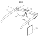
- FIG. 1B is an external configuration diagram of another HMD in this example.
- the same functions as in FIG. 1A are denoted by the same reference numerals, and their explanations will be omitted.
- the difference between FIG. 1B and FIG. 1A is that the control section 18 is divided into 18a and 18b.
- control unit 18a and the control unit 18b are connected through a wired or wireless interface.
- the control unit 18b is, for example, a general-purpose information terminal such as a smartphone or a smart watch.
- a part of the control unit 18 shown in FIG. 1A may be provided as the control unit 18a, so there is an advantage that the HMD 2 can be made smaller and lighter.
- FIG. 2 is a functional block diagram of the HMD in this embodiment.
- FIG. 2 shows the case of the HMD 1 in FIG. 1A, and particularly shows details of a functional block diagram of the control unit 18. Note that the same blocks as in FIG. 1A are denoted by the same reference numerals, and the explanation thereof will be omitted.
- the projection units 12A and 12B in FIG. 1A are collectively referred to as the projection unit 12, and a microphone, speaker, etc. are omitted.
- control unit 18 includes an image recognition processing unit 20, a communication unit 21, a map information processing unit 22, a virtual object processing unit 23, a display processing unit 24, a position detection processing unit 25, an auxiliary information processing unit 26, an overall control It has a section 27.
- the position detection processing unit 25 includes a GPS, a direction, a gyro sensor, etc., and detects the position and orientation of the HMD.
- the map data downloaded by the communication section 21 is input to the map information processing section 22 .
- the map information processing unit 22 extracts map elements such as roads that are set in advance as a driving course from the map data, and outputs them to the virtual object processing unit 23 as extracted information.
- the map information processing section 22 either holds course data of the user's travel schedule or obtains it via the communication section 21, and uses it to extract map elements from the map data.
- the image recognition processing unit 20 inputs the camera image of the camera 10 and the distance data of the ranging sensor 11, recognizes real objects such as roads and buildings from the real space captured by the camera image, and performs processing on the feature points of the real objects. Add distance data.
- the virtual object processing unit 23 calculates the position of the competitor based on the competitor's running pace information, and further generates image data of the virtual object.
- the image data of the virtual object may be obtained from an external server via the communication unit 21.
- the virtual object processing section 23 obtains the current position of the user from the position detection processing section 25, and arranges the virtual object in accordance with the extracted information such as the driving course. Furthermore, by sending the position of the virtual object to the position detection processing section 25, the range of the map data to be downloaded is determined. Although the download range of map data changes from moment to moment, the amount of data to be downloaded can be kept small by updating the difference from the range that has already been downloaded.
- the auxiliary information processing unit 26 executes processing such as generating a course object of auxiliary information in accordance with the course data from the extracted information such as the driving course, and furthermore, the display processing unit 24 Inputs an object, a virtual object from the virtual object processing unit 23, and a real object from the image recognition processing unit 20, performs occlusion processing between the virtual object and course object, and the real object, and projects a virtual object image and a course object image. 12 and displayed on the screen 13.
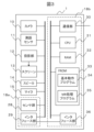
- FIG. 3 is a block diagram of the hardware configuration of the HMD in this embodiment, and shows the case of the HMD 1 in FIG. 1A.
- blocks that are the same as those in FIG. 1A are denoted by the same reference numerals, and their explanations will be omitted.
- the control section 18 is shown divided into control sections 18a and 18b shown in FIG. 1B.
- control unit 18a includes a sensor group 28 including a GPS, a direction sensor, a gyro sensor, etc., and an interface unit 29, and the control unit 18b includes a communication unit 30, a CPU 31, a RAM 32, a Flash ROM (FROM) 33, and an interface unit 29. 36.
- sensor group 28 including a GPS, a direction sensor, a gyro sensor, etc.
- control unit 18b includes a communication unit 30, a CPU 31, a RAM 32, a Flash ROM (FROM) 33, and an interface unit 29. 36.
- the communication unit 30 of the control unit 18b selects an appropriate process from among several communication processes such as mobile communication such as 4G and 5G, and wireless LAN, connects the HMD to the network, and transfers map data etc. to an external server. Download from.
- the FROM 33 includes a basic program 34 and an MR processing program 35 as processing programs. These processing programs can be expanded to the RAM 32 and processed by software in the CPU 31 to realize the various functions shown in FIG. Furthermore, the FROM 33 stores data necessary to execute the processing program.
- the FROM 33 may be a single memory medium as illustrated, or may be composed of a plurality of memory media. Furthermore, a nonvolatile memory medium other than Flash ROM may be used.
- the interface units 29 and 36 may not be provided.
- control unit 18 is divided into control units 18a and 18b as shown in FIG. 1B
- the control unit 18b portion is separated from the HMD in FIG. and 36.
- the interface units 29 and 36 may be wired such as USB (registered trademark), or wireless such as wireless LAN or Bluetooth (registered trademark).
- the HMD only needs to have the control unit 18a, which is a part of the control unit 18, so the HMD can be made smaller. , weight reduction becomes possible.
- FIG. 4 is a flowchart of MR processing in this embodiment.
- the process starts at step S10, and step S11 is the position detection process of the position detection processing section 25 explained in FIG.
- step S11 the current position of the HMD is detected based on data from the sensor group 28, and a download request for map data is output together with the position of a virtual object (to be described later).
- step S12 the current position of the HMD and the position of the virtual object are stored as a travel record at regular time intervals.
- Steps S13 to S15 are map information processing by the map information processing section 22 described in FIG. 2. Map data is downloaded in S13, course data is read in S15, and roads and the like set as a driving course are extracted as map elements by referring to the read course data in S14.
- Step S16 is a step of camera photographing and distance measurement in the camera processing unit, and captures the camera image and distance data.
- Steps S17 and S18 are image recognition processing by the image recognition processing section 20 described in FIG. 2.
- real objects such as roads and buildings are recognized from the camera image, which is an image of real space
- distance data is linked to the feature points of the recognized real objects.
- Steps S20 to S23 are virtual object processing by the virtual object processing unit 23 described in FIG. 2.
- the size of the image of the virtual object changes depending on the direct viewing distance from the HMD, and the orientation changes depending on the direction from the HMD.
- a virtual object is placed on the road of the extracted driving course.
- the range of the map data to be downloaded is determined by sending the placement position of the virtual object to the position detection process S11.
- a course object is an object indicating a road along a driving course, and may be a three-dimensional object reflecting distance data.
- a distance information object indicating numerical data of distance information may be provided in a milestone manner.
- a pseudo course object may be generated instead of the course object.
- the pseudo course object may reflect only the sense of distance from competitors. Note that these course objects, distance information objects, pseudo-course objects, etc. are objects related to a map, so they are also referred to as map element objects.
- Steps S25 to S27 are display processing of the display processing section 24 described in FIG. 2.
- occlusion processing is performed between real objects and virtual objects (including course objects).
- real objects and virtual objects in real space are compared in terms of distance from the user, and parts of the virtual object are closer to each other than the real objects, and parts of the virtual objects are further away from the real objects. distinguish between
- step S27 the virtual object and the auxiliary information object are output and projected on the display section of the HMD. Then, in step S28, it is confirmed whether the program has ended, and if the program has not ended (No), the program returns to immediately after S10, and if it has ended (Yes), the program ends in S29.
- FIG. 5 is a flowchart of the virtual object generation process (S22) in FIG. 4.
- S50 it is determined in S50 whether the competitor is ahead of the user, and if the competitor is ahead (YES), a virtual object is generated in the real space in S51, and if the competitor is not ahead (NO). ), a rearview mirror object is generated in S52, and a virtual object is placed within the rearview mirror object.
- FIG. 6 is a flowchart of the virtual object placement process (S23) in FIG. 4.
- the road width is determined for the road elements obtained as information extracted from the map data in S60. If the road width is wide (YES), it is further determined in S61 whether there is a sidewalk, and if there is a sidewalk (YES), a virtual object is placed on the sidewalk in S62, and if there is no sidewalk (NO), the virtual object is placed on the road edge in S63. Place a virtual object in . If it is determined in S60 that the road width is narrow (NO), a virtual object is placed within the road in S64. The virtual objects in S62 to S64 are placed at positions corresponding to the distance measured along the driving course.
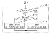
- FIG. 7 is a flowchart of the course object generation process (S25) in FIG. 4.
- the competitor is far ahead in S70, or the course is set to return to the direction opposite to the user's running direction in S71, and in either case, the competitor is far ahead of the user from the user's viewing angle. Determine if it has come off. If the competitor is within the user's viewing angle (NO in both S70 and S71), a course object that matches the road is generated in S72, and if the competitor is outside the user's viewing angle (NO in both S70 and S71) (Yes), a pseudo course object is created in S73.
- the pseudo course object is a course object that reflects only the sense of distance to competitors and is unrelated to roads in real space.
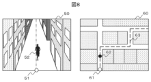
- FIG. 8 is a display example where a competitor is ahead of the user but is visible without being hidden by a real object.
- the left side is the HMD display image 50 that the user sees
- the right side is the corresponding map 60.
- 51 and 61 are users
- 52 and 62 are competitors (virtual objects, especially 52 is an avatar)
- 63 is a running course.
- a user 51 is not included in the display image 50, but is written to indicate the user's position for reference.
- the competitor 52 has an image displayed as a virtual object.
- FIG. 9 is a display example where a competitor is ahead of the user, but is hidden behind a building, which is a real object, and cannot be seen.
- the same components as in FIG. 8 are designated by the same reference numerals, and their explanations will be omitted. 9 differs from FIG. 8 in that a course object 54 and a distance information object 55, which are auxiliary information objects, are added.
- a virtual object, the competitor 52 is hidden behind a real object, a building, and is essentially invisible. Users will not lose sight of their competitors.
- the course object 54 is also partially hidden by a building, which is a real object, but the hidden part is displayed in a different drawing form from the non-hidden part to guide the user about the driving course. Further, the distance information object 55 is displayed to give the user an accurate sense of distance.
- FIG. 10 is an example of placing a virtual object at a specific position.
- the same components as in FIG. 8 are denoted by the same reference numerals, and the description thereof will be omitted.
- FIG. 10 when the road width of the driving course is wide and a sidewalk 56 is installed, virtual objects are placed on the sidewalk 56 so that obstacles such as cars on the roadway and the virtual object competitors 52 do not overlap. A competitor 52 is placed.
- FIG. 11 is an example of a display when a competitor is following the user.
- the same components as those in FIG. 8 are denoted by the same reference numerals, and the description thereof will be omitted.
- a rearview mirror object 57 is displayed at a specific position of the display image 50 of the HMD, for example at the top.
- FIG. 12 shows a case where a competitor is far ahead of the user, or when the running course is meandering as shown in the map on the right side of FIG.
- This is an example of a display when the virtual object is outside the visible range (in other words, when the virtual object is outside the visible range).
- the same components as those in FIG. 9 are denoted by the same reference numerals, and the explanation thereof will be omitted.
- a pseudo course object 58 including a course object 54 is displayed, and virtual objects such as a competitor 52, a distance information object 55, etc. are displayed on the pseudo course object 58.
- the pseudo-course object 58 is a three-dimensional object that gradually moves away from the user 51, for example, using perspective.
- the competitor 52 which is a virtual object
- the competitor 52 is placed on the pseudo-course object 58 at a position where the distance is equivalently transformed according to the distance in front of the competitor, and the user visually recognizes the competitor.
- the time distance is made to reflect the actual distance. This improves the sense of actual distance of the virtual course, which can be used to improve runners' performance. Note that only one of the pseudo course object 58 and the virtual object competitor 52 may be displayed.
- the virtual object display method in this embodiment includes display processing, position detection processing, map information processing, virtual object processing, auxiliary information processing, and image recognition processing.
- the position detection process specifies the user's position on the map, and the map information process extracts roads and the like that have been set as travel courses in advance.
- Virtual object processing generates virtual objects such as competitors. The virtual object is given a relative position with respect to the user and a position on the travel course of the virtual object.
- the image recognition process recognizes a real object from an image in real space, and the display process determines whether a virtual object is within the visible range of the user and distinguishes between a virtual object outside the visible range and a virtual object within the visible range. are displayed in different formats.
- the auxiliary information processing displays information such as the driving course extracted by the map information processing as an auxiliary information object.
- the device for displaying a virtual object in this embodiment includes a display processing section, a position detection processing section, a map information processing section, a virtual object processing section, an auxiliary information processing section, a camera section, and an image recognition processing section.
- the position detection processing section specifies the user's position on the map, and the map information processing section extracts roads etc. that are set in advance as a driving course.
- the virtual object processing unit generates virtual objects such as competitors. The virtual object is given a relative position with respect to the user and a position on the travel course of the virtual object.
- the image recognition processing unit recognizes a real object from an image of real space obtained by a camera, and the display processing unit determines whether a virtual object is within the visible range of the user, and displays virtual objects that are outside the visible range of the user. Display the virtual object in a different form than the virtual object inside. Further, the auxiliary information processing section displays information such as the driving course extracted by the map information processing as an auxiliary information object.
- the present invention is not limited to the embodiments described above, and includes various modifications.
- the present invention is not necessarily limited to having all the configurations described in the embodiments.
- a smartphone or a car navigation system may be used instead of an HMD.
- the functions of the above-mentioned embodiment have been described as being processed by software, but some or all of them may be realized in hardware by, for example, designing an integrated circuit.
- the scope of software implementation is not limited, and hardware and software may be used together.
- a part or all of each function may be realized by a server.
- the server only needs to be able to execute functions in cooperation with other components via communication, and may be, for example, a local server, a cloud server, an edge server, a network service, etc., and its form does not matter.
- information such as programs, tables, files, etc. that realize each function is stored in memory, recording devices such as hard disks, SSDs (Solid State Drives), or recording media such as IC cards, SD cards, and DVDs. It may also be stored in a device on a communication network.
- each processing example may be independent programs, or a plurality of programs may constitute one application program. Furthermore, the order in which each process is performed may be changed.
Landscapes
- Engineering & Computer Science (AREA)
- Physics & Mathematics (AREA)
- General Physics & Mathematics (AREA)
- Theoretical Computer Science (AREA)
- Computer Hardware Design (AREA)
- Software Systems (AREA)
- Computer Graphics (AREA)
- General Engineering & Computer Science (AREA)
- Geometry (AREA)
- Remote Sensing (AREA)
- Processing Or Creating Images (AREA)
- User Interface Of Digital Computer (AREA)
Abstract
Description
Claims (10)
- 地図データから位置情報に対応した第1の地図要素と所定のパターンに対応する第2の地図要素を抽出する地図情報処理ステップと、
前記第1の地図要素に対応する現実空間の現実オブジェクト上に仮想オブジェクトを配置する仮想オブジェクト処理ステップと、
前記第2の地図要素に対応した地図要素オブジェクトを生成する補助情報処理ステップと、
前記仮想オブジェクトおよび前記地図要素オブジェクトにおいて、前記現実オブジェクトの前に位置する部分と後ろに位置する部分とで描画方法を異ならせる表示処理ステップと、
前記表示処理ステップで処理した前記仮想オブジェクトおよび前記地図要素オブジェクトを前記現実空間に重畳表示する表示ステップを有することを特徴とする仮想オブジェクトの表示方法。 - 請求項1に記載の仮想オブジェクトの表示方法であって、
前記仮想オブジェクトは仮想空間内の競争者であり、
前記地図要素オブジェクトはコースオブジェクトであり、
前記表示ステップは、前記競争者および前記コースオブジェクトを前記現実空間に重畳表示することを特徴とする仮想オブジェクトの表示方法。 - 請求項2に記載の仮想オブジェクトの表示方法であって、
前記地図要素オブジェクトは距離情報オブジェクトを含み、
前記表示ステップは、前記競争者および前記コースオブジェクトと前記距離情報オブジェクトを前記現実空間に重畳表示することを特徴とする仮想オブジェクトの表示方法。 - 請求項1に記載の仮想オブジェクトの表示方法であって、
前記仮想オブジェクトは仮想空間内の競争者であり、
前記地図要素オブジェクトは距離情報オブジェクトであり、
前記表示ステップは、前記競争者および前記距離情報オブジェクトを前記現実空間の特定位置に重畳表示することを特徴とする仮想オブジェクトの表示方法。 - 請求項2に記載の仮想オブジェクトの表示方法であって、
補助情報処理ステップは、前記競争者が前記表示ステップで表示ずる画像の表示範囲外にある時、前記地図要素オブジェクトとして疑似コースオブジェクトを生成し、
前記表示ステップは、前記疑似コースオブジェクト上に前記競争者を配置し、使用者が視認する前記競争者の距離感を、前記使用者と前記競争者との間の距離に対応させるように表示することを特徴とする仮想オブジェクトの表示方法。 - 地図データから位置情報に対応した第1の地図要素と所定のパターンに対応する第2の地図要素を抽出する地図情報処理部と、
前記第1の地図要素に対応する現実空間の現実オブジェクト上に仮想オブジェクトを配置する仮想オブジェクト処理部と、
前記第2の地図要素に対応した地図要素オブジェクトを生成する補助情報処理部と、
前記仮想オブジェクトおよび前記地図要素オブジェクトにおいて、前記現実オブジェクトの前に位置する部分と後ろに位置する部分とで描画方法を異ならせ、該描画方法を異ならせた前記仮想オブジェクトおよび前記地図要素オブジェクトを前記現実空間に重畳表示する表示処理部を有することを特徴とする仮想オブジェクトを表示する装置。 - 請求項6に記載の仮想オブジェクトを表示する装置であって、
前記仮想オブジェクトは仮想空間内の競争者であり、
前記地図要素オブジェクトはコースオブジェクトであり、
前記表示処理部は、前記競争者および前記コースオブジェクトを前記現実空間に重畳表示することを特徴とする仮想オブジェクトを表示する装置。 - 請求項7に記載の仮想オブジェクトを表示する装置であって、
前記地図要素オブジェクトは距離情報オブジェクトを含み、
前記表示処理部は、前記競争者および前記コースオブジェクトと前記距離情報オブジェクトを前記現実空間に重畳表示することを特徴とする仮想オブジェクトを表示する装置。 - 請求項6に記載の仮想オブジェクトを表示する装置であって、
前記仮想オブジェクトは仮想空間内の競争者であり、
前記地図要素オブジェクトは距離情報オブジェクトであり、
前記表示処理部は、前記競争者および前記距離情報オブジェクトを前記現実空間の特定位置に重畳表示することを特徴とする仮想オブジェクトを表示する装置。 - 請求項7に記載の仮想オブジェクトを表示する装置であって、
前記補助情報処理部は、前記競争者が前記表示処理部で表示ずる画像の表示範囲外にある時、前記地図要素オブジェクトとして疑似コースオブジェクトを生成し、
前記表示処理部は、前記疑似コースオブジェクト上に前記競争者を配置し、使用者が視認する前記競争者の距離感を、前記使用者と前記競争者との間の距離に対応させるように表示することを特徴とする仮想オブジェクトを表示する装置。
Priority Applications (5)
| Application Number | Priority Date | Filing Date | Title |
|---|---|---|---|
| JP2024524514A JPWO2023233447A1 (ja) | 2022-05-30 | 2022-05-30 | |
| PCT/JP2022/021884 WO2023233447A1 (ja) | 2022-05-30 | 2022-05-30 | 仮想オブジェクトを表示する装置およびその表示方法 |
| US18/869,945 US20250329119A1 (en) | 2022-05-30 | 2022-05-30 | Virtual object display device and virtual object display method |
| CN202280096302.6A CN119156661A (zh) | 2022-05-30 | 2022-05-30 | 显示虚拟对象的装置及其显示方法 |
| JP2025196729A JP2026027478A (ja) | 2022-05-30 | 2025-11-17 | 仮想オブジェクトを表示する装置およびその表示方法 |
Applications Claiming Priority (1)
| Application Number | Priority Date | Filing Date | Title |
|---|---|---|---|
| PCT/JP2022/021884 WO2023233447A1 (ja) | 2022-05-30 | 2022-05-30 | 仮想オブジェクトを表示する装置およびその表示方法 |
Publications (1)
| Publication Number | Publication Date |
|---|---|
| WO2023233447A1 true WO2023233447A1 (ja) | 2023-12-07 |
Family
ID=89025884
Family Applications (1)
| Application Number | Title | Priority Date | Filing Date |
|---|---|---|---|
| PCT/JP2022/021884 Ceased WO2023233447A1 (ja) | 2022-05-30 | 2022-05-30 | 仮想オブジェクトを表示する装置およびその表示方法 |
Country Status (4)
| Country | Link |
|---|---|
| US (1) | US20250329119A1 (ja) |
| JP (2) | JPWO2023233447A1 (ja) |
| CN (1) | CN119156661A (ja) |
| WO (1) | WO2023233447A1 (ja) |
Citations (9)
| Publication number | Priority date | Publication date | Assignee | Title |
|---|---|---|---|---|
| WO2015033446A1 (ja) * | 2013-09-06 | 2015-03-12 | 株式会社フューチャースコープ | ランニング支援システムおよびこれに用いるヘッドマウントディスプレイ装置 |
| WO2018179305A1 (ja) * | 2017-03-31 | 2018-10-04 | 本田技研工業株式会社 | 走行経路提供システムおよびその制御方法、並びにプログラム |
| JP2019012236A (ja) * | 2017-06-30 | 2019-01-24 | パナソニックIpマネジメント株式会社 | 表示システム、情報提示システム、表示システムの制御方法、プログラム、及び移動体 |
| JP2019086508A (ja) * | 2017-11-09 | 2019-06-06 | 三星電子株式会社Samsung Electronics Co.,Ltd. | 仮想経路を表示する方法、装置及びディスプレイ装置 |
| JP2019204438A (ja) * | 2018-05-25 | 2019-11-28 | 株式会社アールビーズ | 動画作成システムおよび動画作成プログラム |
| WO2020066682A1 (ja) * | 2018-09-28 | 2020-04-02 | ソニー株式会社 | 情報処理装置、情報処理方法、及びプログラム |
| US10789723B1 (en) * | 2018-04-18 | 2020-09-29 | Facebook, Inc. | Image object extraction and in-painting hidden surfaces for modified viewpoint rendering |
| JP2022039113A (ja) * | 2020-08-27 | 2022-03-10 | 本田技研工業株式会社 | 自動運転車用情報提示装置 |
| JP2022043996A (ja) * | 2020-09-04 | 2022-03-16 | 株式会社デンソー | 表示制御装置及び表示制御プログラム |
Family Cites Families (3)
| Publication number | Priority date | Publication date | Assignee | Title |
|---|---|---|---|---|
| JP2015166816A (ja) * | 2014-03-04 | 2015-09-24 | 富士通株式会社 | 表示装置,表示制御プログラム及び表示制御方法 |
| WO2018167844A1 (ja) * | 2017-03-14 | 2018-09-20 | マクセル株式会社 | ヘッドアップディスプレイ装置とその画像表示方法 |
| KR20210009529A (ko) * | 2019-07-17 | 2021-01-27 | 네이버랩스 주식회사 | Hd 맵과 hud를 활용한 tbt 정보를 안내하는 방법 및 시스템 |
-
2022
- 2022-05-30 WO PCT/JP2022/021884 patent/WO2023233447A1/ja not_active Ceased
- 2022-05-30 JP JP2024524514A patent/JPWO2023233447A1/ja active Pending
- 2022-05-30 CN CN202280096302.6A patent/CN119156661A/zh active Pending
- 2022-05-30 US US18/869,945 patent/US20250329119A1/en active Pending
-
2025
- 2025-11-17 JP JP2025196729A patent/JP2026027478A/ja active Pending
Patent Citations (9)
| Publication number | Priority date | Publication date | Assignee | Title |
|---|---|---|---|---|
| WO2015033446A1 (ja) * | 2013-09-06 | 2015-03-12 | 株式会社フューチャースコープ | ランニング支援システムおよびこれに用いるヘッドマウントディスプレイ装置 |
| WO2018179305A1 (ja) * | 2017-03-31 | 2018-10-04 | 本田技研工業株式会社 | 走行経路提供システムおよびその制御方法、並びにプログラム |
| JP2019012236A (ja) * | 2017-06-30 | 2019-01-24 | パナソニックIpマネジメント株式会社 | 表示システム、情報提示システム、表示システムの制御方法、プログラム、及び移動体 |
| JP2019086508A (ja) * | 2017-11-09 | 2019-06-06 | 三星電子株式会社Samsung Electronics Co.,Ltd. | 仮想経路を表示する方法、装置及びディスプレイ装置 |
| US10789723B1 (en) * | 2018-04-18 | 2020-09-29 | Facebook, Inc. | Image object extraction and in-painting hidden surfaces for modified viewpoint rendering |
| JP2019204438A (ja) * | 2018-05-25 | 2019-11-28 | 株式会社アールビーズ | 動画作成システムおよび動画作成プログラム |
| WO2020066682A1 (ja) * | 2018-09-28 | 2020-04-02 | ソニー株式会社 | 情報処理装置、情報処理方法、及びプログラム |
| JP2022039113A (ja) * | 2020-08-27 | 2022-03-10 | 本田技研工業株式会社 | 自動運転車用情報提示装置 |
| JP2022043996A (ja) * | 2020-09-04 | 2022-03-16 | 株式会社デンソー | 表示制御装置及び表示制御プログラム |
Also Published As
| Publication number | Publication date |
|---|---|
| CN119156661A (zh) | 2024-12-17 |
| JPWO2023233447A1 (ja) | 2023-12-07 |
| US20250329119A1 (en) | 2025-10-23 |
| JP2026027478A (ja) | 2026-02-18 |
Similar Documents
| Publication | Publication Date | Title |
|---|---|---|
| CN113063418B (zh) | 用于显示3d增强现实导航信息的方法和装置 | |
| CN112753050B (zh) | 信息处理装置、信息处理方法和程序 | |
| EP2860971B1 (en) | Display control apparatus, method, recording medium, and vehicle | |
| JP6775188B2 (ja) | ヘッドアップディスプレイ装置および表示制御方法 | |
| US9122053B2 (en) | Realistic occlusion for a head mounted augmented reality display | |
| US9583032B2 (en) | Navigating content using a physical object | |
| US20190162964A1 (en) | Space carving based on human physical data | |
| JP6410874B1 (ja) | Ar映像生成装置 | |
| JP6946963B2 (ja) | 重畳画像表示装置及びコンピュータプログラム | |
| WO2015174050A1 (ja) | 表示装置および表示方法 | |
| JP2015204616A (ja) | ヘッドマウントディスプレイの提示の調整 | |
| JP2016512626A (ja) | ウェアラブルな行動ベース視覚システム | |
| JP2019206256A (ja) | 表示制御装置、及び表示制御プログラム | |
| KR20170107432A (ko) | 3차원 지도 표시 시스템 | |
| WO2022004422A1 (ja) | 情報処理装置、情報処理方法、及び記録媒体 | |
| KR102431493B1 (ko) | 증강현실 콘텐츠 기반 차량기능 안내 및 가상 시험주행 경험 제공 시스템 및 방법 | |
| KR102641118B1 (ko) | 사용자에게 ar 오브젝트를 제공하는 방법 및 장치 | |
| KR100886330B1 (ko) | 사용자 뷰 출력 시스템 및 방법 | |
| JP2017116279A (ja) | 案内装置、制御方法、プログラム、及び記憶媒体 | |
| JP2026027478A (ja) | 仮想オブジェクトを表示する装置およびその表示方法 | |
| JP6448806B2 (ja) | 表示制御装置、表示装置及び表示制御方法 | |
| CN118810431A (zh) | 显示控制装置、显示系统及显示控制方法 | |
| JP6984341B2 (ja) | 重畳画像表示装置及びコンピュータプログラム | |
| JP7143728B2 (ja) | 重畳画像表示装置及びコンピュータプログラム | |
| JP2021160409A (ja) | 表示制御装置、画像表示装置、及び方法 |
Legal Events
| Date | Code | Title | Description |
|---|---|---|---|
| 121 | Ep: the epo has been informed by wipo that ep was designated in this application |
Ref document number: 22944737 Country of ref document: EP Kind code of ref document: A1 |
|
| WWE | Wipo information: entry into national phase |
Ref document number: 2024524514 Country of ref document: JP |
|
| WWE | Wipo information: entry into national phase |
Ref document number: 202280096302.6 Country of ref document: CN |
|
| WWE | Wipo information: entry into national phase |
Ref document number: 18869945 Country of ref document: US |
|
| NENP | Non-entry into the national phase |
Ref country code: DE |
|
| 122 | Ep: pct application non-entry in european phase |
Ref document number: 22944737 Country of ref document: EP Kind code of ref document: A1 |
|
| WWP | Wipo information: published in national office |
Ref document number: 18869945 Country of ref document: US |