WO2023228945A1 - モータ駆動制御装置、モータユニット、およびモータ駆動制御方法 - Google Patents
モータ駆動制御装置、モータユニット、およびモータ駆動制御方法 Download PDFInfo
- Publication number
- WO2023228945A1 WO2023228945A1 PCT/JP2023/019180 JP2023019180W WO2023228945A1 WO 2023228945 A1 WO2023228945 A1 WO 2023228945A1 JP 2023019180 W JP2023019180 W JP 2023019180W WO 2023228945 A1 WO2023228945 A1 WO 2023228945A1
- Authority
- WO
- WIPO (PCT)
- Prior art keywords
- motor
- commutation mode
- drive control
- rotational speed
- rotation speed
- Prior art date
- Legal status (The legal status is an assumption and is not a legal conclusion. Google has not performed a legal analysis and makes no representation as to the accuracy of the status listed.)
- Ceased
Links
Images



Classifications
-
- H—ELECTRICITY
- H02—GENERATION; CONVERSION OR DISTRIBUTION OF ELECTRIC POWER
- H02P—CONTROL OR REGULATION OF ELECTRIC MOTORS, ELECTRIC GENERATORS OR DYNAMO-ELECTRIC CONVERTERS; CONTROLLING TRANSFORMERS, REACTORS OR CHOKE COILS
- H02P6/00—Arrangements for controlling synchronous motors or other dynamo-electric motors using electronic commutation dependent on the rotor position; Electronic commutators therefor
- H02P6/14—Electronic commutators
- H02P6/16—Circuit arrangements for detecting position
- H02P6/18—Circuit arrangements for detecting position without separate position detecting elements
- H02P6/182—Circuit arrangements for detecting position without separate position detecting elements using back-emf in windings
-
- H—ELECTRICITY
- H02—GENERATION; CONVERSION OR DISTRIBUTION OF ELECTRIC POWER
- H02P—CONTROL OR REGULATION OF ELECTRIC MOTORS, ELECTRIC GENERATORS OR DYNAMO-ELECTRIC CONVERTERS; CONTROLLING TRANSFORMERS, REACTORS OR CHOKE COILS
- H02P8/00—Arrangements for controlling dynamo-electric motors rotating step by step
- H02P8/14—Arrangements for controlling speed or speed and torque
Definitions
- the present invention relates to a motor drive control device, a motor unit, and a motor drive control method, and for example, to a motor drive control device for driving a stepping motor.
- a motor drive control device that detects a zero cross of a back electromotive force of a coil of a motor and commutates the coil (see, for example, Patent Document 1).
- the inventor of this application studied a new motor drive control technology. Specifically, when the rotational speed of the motor is lower than a threshold value, the drive of the motor is controlled by a first commutation mode in which the coil is commutated based on the detection result of the zero cross of the back electromotive voltage of the motor coil. , a motor drive control technology that controls motor drive through a second commutation mode in which coil commutation is performed to prevent the motor rotation speed from exceeding a target rotation speed when the motor rotation speed exceeds a threshold value.
- the inventor of the present application has considered the following.
- the first commutation mode when the rotational speed of the motor is lower than the threshold value, the first commutation mode allows the motor to be rotated with an appropriate torque and rotational speed according to the load of the motor.
- the second commutation mode rotates the motor so as not to exceed the target rotation speed, thereby increasing the motor rotation speed. can be suppressed.
- the commutation mode is switched from the first commutation mode to the second commutation mode after the load on the motor becomes lighter and the rotational speed of the motor exceeds a threshold value.
- the motor is controlled so that the rotational speed quickly falls below the target rotational speed, so the operation of the motor rotor becomes abnormal, the rotational speed drops significantly below the threshold, and the commutation mode changes to the first rotation.
- it goes back to flow mode. In this case, since the back electromotive voltage is also disturbed, zero crossing of the back electromotive voltage does not occur, and commutation of the coil in the first commutation mode is not performed appropriately, which may cause the motor to stop.
- the present invention has been made in view of the above-mentioned problems, and an object of the present invention is to improve the stability of motor operation when switching between commutation modes.
- a motor drive control device includes a control circuit that generates a drive control signal for controlling the drive of a motor, and a control circuit that drives a coil of the motor based on the drive control signal.
- a drive circuit, and the control circuit is configured to operate in a first commutation mode in which the coil is commutated based on a detection result of a zero cross of a back electromotive voltage in the coil, or in a first commutation mode in which the rotational speed of the motor is Commutation mode setting in which a second commutation mode in which the coil is commutated so as not to exceed a target rotational speed that is a target value of the rotational speed is selected based on the rotational speed of the motor and set as the commutation mode.
- a target rotational speed setting section that sets the target rotational speed
- a drive control signal generation section that generates the drive control signal based on the commutation mode set by the commutation mode setting section.
- the target rotational speed setting section is configured to reduce the target rotational speed in stages to a final target value when the commutation mode is switched from the first commutation mode to the second commutation mode. It is characterized by
- the motor drive control device According to the motor drive control device according to the present invention, it is possible to improve the stability of the motor operation when switching the commutation mode.
- FIG. 2 is a block diagram showing the configuration of a motor unit according to an embodiment.
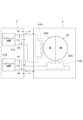
- FIG. 3 is a diagram schematically showing the configuration of a motor.
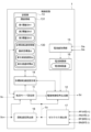
- FIG. 2 is a diagram showing the configuration of a control circuit in a motor drive control device according to an embodiment.
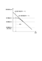
- FIG. 3 is a diagram showing the relationship between the magnitude of motor load and rotation speed in each commutation mode. It is a figure showing an example of deceleration processing by a motor drive control device concerning an embodiment.
- 5 is a timing chart showing an example of control of the rotational speed of a motor by the motor drive control device according to the embodiment.
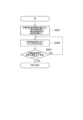
- It is a flow chart which shows the flow of commutation mode switching processing by a motor drive control device concerning an embodiment.
- 8 is a diagram showing the flow of step S5 (deceleration processing) in FIG. 7.
- FIG. 7 is a diagram schematically showing the configuration of a motor.
- FIG. 2 is a diagram showing the configuration of a control circuit in a motor drive control
- a motor drive control device (3) includes a control circuit (1) that generates a drive control signal (Sd) for controlling the drive of a motor (4); a drive circuit (2) that drives the coils (41, 41A, 41B) of the motor based on the drive control signal; a first commutation mode in which the coil is commutated in a manner such that the rotational speed of the motor does not exceed a target rotational speed that is a target value of the rotational speed of the motor; a commutation mode setting unit (11) that selects a current mode based on the rotational speed of the motor and sets it as a commutation mode; a target rotational speed setting unit (14) that sets the target rotational speed; a drive control signal generation section (12) that generates the drive control signal based on the commutation mode set by the flow mode setting section;
- the present invention is characterized in that when switching from the first commutation mode to the second commutation mode, the target rotational speed
- the target rotation speed setting section controls the change in the target rotation speed with respect to time when the target rotation speed is gradually lowered to a final target value.
- the ratio may be constant.
- the target rotation speed setting section controls the change in the target rotation speed with respect to time when the target rotation speed is gradually lowered to a final target value.
- the proportion may be varied.
- the control circuit has a unit deceleration time ( ⁇ t) indicating a unit of time for decelerating the target rotation speed, and a unit deceleration time ( ⁇ t) indicating a unit of time for decelerating the target rotation speed
- the target rotation speed setting unit further includes a storage unit (13) that stores a unit deceleration speed ( ⁇ s) indicating a unit of speed for decelerating the rotation speed and the final target value (st), and the target rotation speed setting unit
- the target rotational speed may be changed to the final target value at a rate based on the unit deceleration time and unit deceleration speed stored in the unit.
- the commutation mode setting section is configured such that the rotation speed of the motor exceeds a first threshold value (Sth1) for a predetermined period of time (N steps). ) If the commutation mode continues, the commutation mode may be switched from the first commutation mode to the second commutation mode.
- the commutation mode setting unit may set the commutation mode setting unit to The commutation mode may be switched from the second commutation mode to the first commutation mode.
- a motor unit (5) includes the motor (4) and the motor drive control device (3) described in any one of [1] to [6] above. It is characterized by comprising the following.
- a method is a motor drive control method for controlling the drive of a motor (4) by a motor drive control device (3).
- the method includes a first commutation mode in which the motor drive control device commutates the coil based on a detection result of a zero cross of a back electromotive voltage of a coil of the motor, or a first commutation mode in which the rotational speed of the motor is
- the first step includes a third step of generating a drive control signal for controlling the drive of the motor in accordance with the commutation mode;
- the present invention is characterized in that it includes a step (S501 to S503) of decreasing the target rotational speed in stages when switching from the current commutation mode to the second commutation mode.
- FIG. 1 is a block diagram showing the configuration of a motor unit 5 according to an embodiment.
- the motor unit 5 includes a motor 4 and a motor drive control device 3 that drives the motor 4.
- the motor unit 5 is applicable to various devices that use a motor as a power source, such as an actuator that can be used in an HVAC (Heating Ventilation and Air-Conditioning) as an air conditioning unit for vehicle use.
- HVAC Heating Ventilation and Air-Conditioning
- the motor 4 is, for example, a stepping motor. In this embodiment, as an example, it is assumed that the motor 4 is a two-phase stepping motor.
- FIG. 2 is a diagram schematically showing the configuration of the motor 4.
- the motor 4 as a two-phase stepping motor includes an A-phase coil 41A, a B-phase coil 41B, and a rotor 42.
- the coils 41A and 41B are wound around a stator yoke (not shown), and together with the stator yoke constitute a stator. Note that in this embodiment, when the coils 41A and 41B are not distinguished from each other, they may be simply referred to as "coil 41.”
- the rotor 42 includes a permanent magnet that is multipolar magnetized so that south poles 42S and north poles 42N are alternately arranged along the circumferential direction.
- FIG. 2 shows an example in which the rotor 42 has two poles, the number of poles of the rotor 42 is not particularly limited.
- the A-phase stator yoke When current flows through the A-phase coil 41A, the A-phase stator yoke is excited, and when current flows through the B-phase coil 41B, the B-phase stator yoke is excited.
- the rotor 42 rotates by periodically switching the phase of the current flowing through each of the coils 41A and 41B.
- An output shaft (not shown) is connected to the rotor 42, and when the output shaft is driven by the rotational force of the rotor 42, the function as the actuator described above is realized, for example.
- the motor drive control device 3 is a device for driving the motor 4.
- the motor drive control device 3 controls the rotation and stopping of the motor 4 by controlling the energization state of the coils 41A and 41B of each phase of the motor 4 based on the drive command signal Sc from the host device 6, for example. .
- the motor drive control device 3 includes a control circuit 1 and a drive circuit 2.
- the drive circuit 2 is a circuit that energizes the coils 41A and 41B of the motor 4 to drive the motor 4.
- the drive circuit 2 rotates the rotor 42 of the motor 4 by exciting the coils 41A and 41B of the motor 4 based on the drive control signal Sd output from the control circuit 1.
- the drive circuit 2 includes, for example, an inverter circuit 21A for exciting an A-phase coil 41A, an inverter circuit 21B for exciting a B-phase coil 41B, and a current detection circuit for detecting the current of the A-phase coil 41A. 20A, and a current detection circuit 20B that detects the current of the B-phase coil 41B.
- the inverter circuits 21A and 21B are configured by, for example, an H-bridge circuit configured from four switching elements (for example, transistors).
- the inverter circuit 21A will also be referred to as the "H bridge circuit 21A”
- the inverter circuit 21B will also be referred to as the "H bridge circuit 21B”.
- H-bridge circuit 21A and the H-bridge circuit 21B are not distinguished, they are simply referred to as "H-bridge circuit 21.”
- the H-bridge circuit 21A and the H-bridge circuit 21B have the same circuit configuration.
- the H-bridge circuit 21 includes a plurality of switching elements (for example, transistors) whose on/off is controlled by the drive control signal Sd.
- the drive circuit 2 may include a predrive circuit for driving the switching elements of each H bridge circuit 21A, 21B based on the drive control signal Sd.
- the H-bridge circuit 21A is connected to the positive terminal AP of the coil 41A and the negative terminal AN of the coil 41A.
- the H-bridge circuit 21B is connected to a positive terminal BP of the coil 41B and a negative terminal BN of the coil 41B.
- the H-bridge circuits 21A and 21B energize the coils 41A and 41B by applying a voltage to each terminal AP, AN, BP, and BN. Specifically, the H-bridge circuit 21 selectively turns on and off each switching element constituting the H-bridge circuit 21 in accordance with the drive control signal Sd supplied from the control circuit 1, thereby energizing the coil 41. At the same time, the current direction of the coil 41 is switched.
- the H-bridge circuit 21A For example, as shown in FIG. 2, during the "A-phase (+) excitation period" in which current +Ia flows from the terminal AP of the A-phase coil 41A to the terminal AN, the H-bridge circuit 21A, for example, A voltage of "+Va" is applied to the terminal AP.
- the H-bridge circuit 21A connects the terminal AP to the terminal AN of the coil 41A. A voltage of Va'' is applied.
- the H-bridge circuit 21B applies "+Vb" to the terminal BP with respect to the terminal BN of the coil 41B, for example. Apply a voltage of During the "B-phase (-) excitation period” in which current -Ib flows from the terminal BN of the B-phase coil 41B to the terminal BP, the H-bridge circuit 21B applies "-Vb" to the terminal BP with respect to the terminal BN of the coil 41B. Apply a voltage of
- the current detection circuit 20A is connected to the H-bridge circuit 21A, detects the current flowing through the coil 41A, and outputs a current detection signal Sia according to the magnitude of the detected current.
- the current detection circuit 20B is connected to the H-bridge circuit 21B, detects the current flowing through the coil 41B, and outputs a current detection signal Sib according to the magnitude of the detected current.
- the current detection circuits 20A and 20B include, for example, a shunt resistor.
- the shunt resistor is connected in series with the H-bridge circuit 21 between the power supply voltage of the H-bridge circuit 21 and the ground voltage for each H-bridge circuit 21, and the voltage generated across the shunt resistor is used as the current detection signal Sia. , Sib.
- the current detection circuits 20A and 20B can adopt various known circuit configurations capable of detecting the current flowing through the coils 41A and 41B of the motor 4, and are limited to the circuit configuration including the above-mentioned shunt resistor. isn't it.
- the control circuit 1 is a circuit that performs overall control of the motor drive control device 3.
- the control circuit 1 includes, for example, a processor such as a CPU, various storage devices such as RAM and ROM, and peripherals such as a timer (counter), an A/D conversion circuit, a D/A conversion circuit, and an input/output I/F circuit.
- a program processing device for example, a microcontroller
- the control circuit 1 is packaged as, for example, an IC (integrated circuit), but the control circuit 1 is not limited to this. Note that the control circuit 1 and the drive circuit 2 may be packaged into one.
- the control circuit 1 has a function of controlling the drive of the motor 4 by, for example, generating a drive control signal Sd and providing it to the drive circuit 2.
- FIG. 3 is a diagram showing the configuration of the control circuit 1 in the motor drive control device 3 according to the embodiment.
- the control circuit 1 includes a commutation mode setting section 11, a drive control signal generation section 12, a storage section 13, a target rotation speed setting section 14, a current It has a value acquisition section 15, a current limit section 16, a zero cross detection section 17, and a rotation speed calculation section 18.
- These functional units include, for example, a program processing device (microcontroller) as the control circuit 1 described above, in which a processor executes calculations using various parameters stored in a storage device according to a program stored in the storage device. This is realized by controlling peripheral circuits such as A/D conversion circuits and timers. Note that some or all of these functional units may be realized by dedicated circuits (hardware).
- the storage unit 13 is a functional unit for storing various data necessary for motor drive control by the control circuit 1.
- the storage unit 13 stores target rotational speed information 130 including a unit deceleration speed ⁇ s, a unit deceleration time ⁇ t, and a final target value st, a first threshold Sth1, a second threshold Sth2, and a third threshold Sth3, which will be described later.
- Threshold information 131 including the threshold information 131 is stored.
- the commutation mode setting unit 11 is a functional unit for setting a commutation mode that specifies the commutation method of the motor 4.
- the motor drive control device 3 has at least two commutation modes.
- One is a first commutation mode in which the coils 41A and 41B are commutated based on the detection result of the zero cross of the back electromotive force of the coils 41A and 41B, and the other is a first commutation mode in which the rotational speed of the motor 4 is
- This is a second commutation mode in which the coil 41 is commutated so as not to exceed a target rotational speed, which is a target value of the rotational speed.
- the commutation mode setting unit 11 acquires a drive command signal Sc for the motor 4 input from the outside of the motor drive control device 3 (for example, the host device 6).
- the drive command signal Sc includes, for example, information specifying the rotational position of the motor 4, information instructing the rotation of the motor 4 to stop, and the like.
- the drive command signal Sc is, for example, a PWM signal.
- the commutation mode setting unit 11 acquires information on the target rotational position of the motor 4 (target rotational position) by analyzing the drive command signal Sc, and sets the commutation mode to the first commutation mode or the first commutation mode. After setting the two-commutation mode, the drive control signal generation section 12 is instructed to drive the motor 4. Note that the details of how the commutation mode setting section 11 sets the commutation mode will be described later.
- the target rotation speed setting unit 14 is a functional unit for setting a target rotation speed.
- the target rotation speed setting unit 14 sets a target rotation speed when the commutation mode is switched from the first commutation mode to the second commutation mode. Note that details of the method for setting the target rotational speed will be described later.
- the zero cross detection section 17 is a functional section for monitoring the voltages of the coils 41A and 41B and detecting the zero cross of the back electromotive voltage generated in the coils 41A and 41B.
- the zero cross of the back electromotive voltage refers to a state in which the back electromotive voltage generated at both ends of the unexcited coil 41 switches from positive to negative or from negative to positive.
- the zero cross detection unit 17 monitors the voltage between the terminals AP and the terminal AN as the voltage of the coil 41A, and the voltage between the terminals BP and BN as the voltage of the coil 41B, and detects the back electromotive force of the coils 41A and 41B. When a zero-crossing of the voltage is detected, a zero-crossing detection signal Sz indicating that the zero-crossing has been detected is output.
- the rotational speed calculation unit 18 is a functional unit that calculates the rotational speed of the motor 4.
- the rotational speed calculation unit 18 calculates the rotational speed of the motor 4 based on the zero-crossing detection signal Sz output from the zero-crossing detection unit 17 when the zero-crossing of the back electromotive force of the coil 41 is detected periodically. do.
- the rotational speed calculation unit 18 calculates the rotational speed of the motor 4 in the first commutation mode based on the period in which the zero-cross detection signal Sz is output.
- the rotation speed calculation unit 18 calculates the rotation speed based on the target rotation speed (target energization time) set in advance in the second commutation mode. , calculate the rotational speed of the motor 4.
- the rotational speed calculation unit 18 generates an output signal So including information on the calculated rotational speed.
- the output signal So is, for example, output to the outside of the motor drive control device 3 (for example, the host device 6), and is also input to the commutation mode setting section 11.
- the drive control signal generation section 12 generates the drive control signal Sd based on the commutation mode set by the commutation mode setting section 11.
- the drive control signal Sd is a signal for controlling on/off of each switching element of the H bridge circuits 21A and 21B, and is, for example, a PWM signal.
- the drive control signal generation unit 12 excites the A-phase coil 41A and the B-phase coil 41B at a predetermined timing based on a predetermined excitation method in order to move the rotor 42 to a target rotational position or a target standby position. , generates and outputs a drive control signal Sd.
- the predetermined excitation method may be any excitation method that can detect the back electromotive force of the coil 41, and is, for example, a known one-phase excitation method or a 1-2 phase excitation method.
- the drive control signal generation unit 12 When generating the drive control signal Sd by the one-phase excitation method, the drive control signal generation unit 12 generates, for example, "A phase (+) excitation period”, “B phase (+) excitation period”, “A phase (-) The drive control signal Sd is generated and output so that the energization states of the A and B phase coils 41A and 41B are switched in the order of "excitation period” and "B phase (-) excitation period”.
- the switching of each excitation period is performed according to the commutation mode set by the commutation mode setting section 11. Specifically, when the first commutation mode is designated as the commutation mode, the drive control signal generation section 12 controls the coil 41A every time the zero cross detection section 17 detects a zero cross of the back electromotive voltage. , 41B.
- the drive control The signal generation unit 12 switches from the "A phase (+) excitation period” to the "B phase (+) excitation period".
- the drive control signal generation unit 12 controls the coil 41A according to the target rotation speed so that the rotation speed of the motor 4 does not exceed the target rotation speed. , 41B.
- the drive control signal generation section 12 includes a timer (counter).
- the drive control signal generation section 12 acquires, for example, information on a target energization time corresponding to a target rotation speed set by a target rotation speed setting section 14, which will be described later.
- the target energization time is a target value of the length of a period in which one energization pattern (excitation state of the coil 41) is continued.
- the target rotational speed setting unit 14 may calculate the target energization time based on the set target rotational speed and provide it to the drive control signal generation unit 12.
- the drive control signal generation section 12 may calculate the target energization time based on information on the target rotation speed given from the target rotation speed setting section 14. In this embodiment, as will be described later, it is assumed that the target rotational speed setting section 14 calculates the target energization time based on the target rotational speed and provides the calculated target energization time to the drive control signal generation section 12.
- the drive control signal generation unit 12 excites the A-phase coil 41A to positive polarity, and starts measuring time with a timer. do. Then, when the measured time reaches the target energization time, the drive control signal generation unit 12 switches from the "A phase (+) excitation period" to the "B phase (+) excitation period". In this way, in the second commutation mode, the drive control signal generation unit 12 commutates the coil 41 based on the comparison result between the measured time and the target energization time, so that the motor 4 rotates at the target rotational speed. do.
- the drive control signal generation unit 12 detects the zero cross of the back electromotive force (zero cross detection signal) as in the first commutation mode.
- the coils 41A and 41B may be commutated depending on the input voltage Sz. That is, if the zero cross of the back electromotive force is not detected in the second commutation mode, the drive control signal generation unit 12 commutates the coils 41A and 41B based on the target rotational speed (target energization time).
- the coils 41A and 41B are commutated in accordance with the detection of the zero cross of the back electromotive force even in the second commutation mode. You can.
- the rotational speed of the motor 4 changes according to the magnitude of the load as in the first commutation mode, but since the drive control signal generation section 12 also measures the target energization time, the rotational speed of the motor 4 changes to the target rotation speed. None exceed speed.
- the current value acquisition unit 15 is a functional unit that acquires the value of the current flowing through the coils 41A and 41B of each phase of the motor 4.
- Current detection signals Sia and Sib output from the current detection circuits 20A and 20B of the drive circuit 2 are input to the current value acquisition section 15.
- the current value acquisition unit 15 includes, for example, an A/D conversion circuit, and the A/D conversion circuit converts the voltage as the current detection signal Sia into a digital value, and outputs the digital value as the current value of the A-phase coil 41A.
- the current value acquisition unit 15 converts the voltage as the current detection signal Sib into a digital value using, for example, an A/D conversion circuit, and outputs the digital value as a current value of the B-phase coil 41B.
- the current limiter 16 is a functional unit that monitors the current flowing through the coil 41 of the motor 4 and controls the current so that it does not exceed the current limit value.
- the current limit value is a reference value for limiting the current flowing through the coil 41 of the motor 4, in other words, it is a value that determines the upper limit of the current flowing through the coil 41.
- Information on the current limit value is set in advance in the current limiter 16, for example.
- Current monitoring by the current limiter 16 is performed for each phase of the motor 4. For example, during the "A-phase (+) excitation period” and “A-phase (-) excitation period” during which the A-phase coil 41A is excited, the current limiter 16 controls the current of the A-phase coil 41A (current detection signal Sia), and during the "B-phase (+) excitation period” and “B-phase (-) excitation period” during which the B-phase coil 41B is excited, the current limiter 16 controls the current of the B-phase coil 41B. (current detection signal Sib) is monitored.
- the current limiter 16 compares the value of the current flowing through the coil 41 and the current limit value.
- the current limiter 16 instructs the drive control signal generator 12 to stop excitation of the coil 41 when the current flowing through the coil 41 reaches the current limit value.
- the current limiter 16 compares the current value (absolute value) of the coil 41A output from the current value acquisition unit 15 with the current limit value during a period when the A-phase coil 41A is excited.
- the current limiter 16 stops the excitation of the coil 41A when the current value of the coil 41A exceeds the current limit value, that is, turns off each switching element of the H bridge circuit 21A using the drive control signal Sd.
- An instructing signal is output for a predetermined period.
- the current limiter 16 limits the current of the B-phase coil 41B using the same method even during the period when the B-phase coil 41B is excited.
- the drive control signal generation unit 12 generates the drive control signal Sd to stop the excitation of the coil 41 while the current limiter 16 outputs a signal instructing to stop the excitation of the coil 41.
- the drive control signal generator 12 outputs a signal that instructs the A-phase H
- a drive control signal Sd is generated to turn off each switching element in the bridge circuit 21A.
- the power supply to the A-phase coil 41A is stopped, so the current in the A-phase coil 41A decreases and is limited so as not to exceed the current limit value.
- the current of the B-phase coil 41B is also limited by the same method.
- the commutation mode setting unit 11 selects the first commutation mode or the second commutation mode based on the rotational speed of the motor 4 and sets it as the commutation mode. Specifically, the commutation mode setting unit 11 compares the rotational speed of the motor 4 with a threshold value, sets the commutation mode to the second commutation mode when the rotational speed exceeds the threshold value, and sets the commutation mode to the second commutation mode when the rotational speed is lower than the threshold value. When the voltage decreases, the commutation mode is set to the first commutation mode.
- the value of the rotational speed of the motor 4 is calculated by the rotational speed calculation unit 18 as described above.
- the commutation mode setting unit 11 changes the commutation mode from the first commutation mode when the rotational speed of the motor 4 continues to exceed the first threshold value Sth1 for a predetermined period of time (commutation mode transition period). Switch to second commutation mode.
- the unit of the driving amount of the stepping motor is "1 step”
- the commutation mode setting unit 11 switches the commutation mode from the first commutation mode to the second commutation mode.
- the first threshold Sth1 is stored in the storage unit 13 in advance as threshold information 131, for example.
- information (N steps) specifying the length of the commutation mode transition period may also be stored in the storage unit 13.
- the commutation mode setting unit 11 changes the commutation mode from the second commutation mode to the first commutation mode when the rotational speed of the motor 4 decreases below a second threshold value Sth2, which is smaller than the first threshold value Sth1.
- the second threshold value Sth2 is stored in advance in the storage unit 13 as threshold information 131, for example, similarly to the first threshold value Sth1.
- the commutation mode setting unit 11 may detect the presence or absence of an abnormality in the motor 4 based on the rotational speed of the motor 4, and may stop the rotational operation of the motor 4. For example, if a load above a certain level is applied to the motor 4 and the motor 4 loses synchronization, the rotational speed of the motor 4 tends to decrease rapidly. Therefore, the commutation mode setting unit 11 determines that the motor 4 is abnormal (for example, out of synchronization) when the rotational speed of the motor 4 falls below a third threshold Sth3 that is smaller than the second threshold Sth2. , the drive control signal generation unit 12 may be instructed to stop the rotation of the motor 4.
- the third threshold Sth3 may be stored in advance in the storage unit 13 as the threshold information 131, for example, similarly to the first threshold Sth1 and the second threshold Sth2.
- FIG. 4 is a diagram showing the relationship between the magnitude of the load on the motor 4 and the rotation speed in each commutation mode.
- the horizontal axis represents the magnitude of the load on the motor 4, and the vertical axis represents the rotational speed of the motor 4.
- the motor 4 rotates at a rotation speed that corresponds to the magnitude of the load on the motor 4. That is, as shown by reference numeral 400 in FIG. 4, the lighter (smaller) the load, the higher the rotational speed of the motor 4.
- the commutation mode changes from the first commutation mode to the second commutation mode.
- the motor 4 is then controlled to rotate at the target rotation speed set by the target rotation speed setting section 14 .
- the motor 4 is controlled so that the rotational speed becomes the target rotational speed (for example, the first threshold value Sth1), as indicated by reference numeral 401.
- the rotational speed should be constant regardless of the load.
- the motor 4 is controlled so that the rotational speed quickly reaches the target rotational speed when the commutation mode is switched from the first commutation mode to the second commutation mode, as described above, the rotor of the motor 4 42 becomes abnormal, the rotational speed decreases below the second threshold value Sth2, and the commutation mode returns to the first commutation mode, as indicated by a dotted line 403 in FIG. 4.
- the value is less than or equal to the third threshold value Sth3, it is determined that the motor 4 is in an abnormal state, and there is a possibility that the motor 4 may stop.
- the motor drive control device 3 when switching the commutation mode from the first commutation mode to the second commutation mode, performs a deceleration process that changes the target rotational speed in stages.
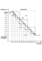
- FIG. 5 is a diagram showing an example of deceleration processing by the motor drive control device 3 according to the embodiment.
- the horizontal axis represents the number of steps when the unit of drive amount of the stepping motor is "1 step”, and corresponds to "elapsed time”. Further, the vertical axis represents the rotation speed (target rotation speed).
- the target rotation speed setting unit 14 sets the target rotation speed to the final target value when the commutation mode is switched from the first commutation mode to the second commutation mode.
- a deceleration process is performed to gradually reduce the speed to st.
- the final target value st is the upper limit value of the rotational speed of the motor 4 in the second commutation mode.
- a unit deceleration time ⁇ t indicating a unit of time for decelerating the target rotation speed, a unit deceleration speed ⁇ s indicating a unit of speed for decelerating the target rotation speed, and a final target value st are set in advance as the target rotation speed information 130. It is stored in the storage unit 13. Based on the target rotation speed information 130 stored in the storage section 13, the target rotation speed setting section 14 changes the target rotation speed to the final target value st at a rate based on the unit deceleration time ⁇ t and the unit deceleration speed ⁇ s.
- the target rotation speed setting unit 14 sets the reference numeral 500.
- the target rotation speed setting unit 14 sets the reference numeral 501 As shown in , the rotational speed of the motor 4 when the commutation mode is switched from the first commutation mode to the second commutation mode is the initial value of the target rotational speed, and "400pps" is set every 4 steps from the initial value. The target rotation speed is gradually lowered to the final target value st (first threshold value Sth1).
- the commutation mode can be changed from the first commutation mode to the second commutation mode.
- the rotational speed of the motor 4 can be reduced linearly.
- the target rotational speed setting unit 14 converts the set target rotational speed into a target energization time and provides it to the drive control signal generation unit 12.
- information on the energization angle which indicates the magnitude of the electrical angle at which the coil 41 of one phase is continuously energized in one direction, is stored in advance in the storage unit 13 according to the excitation method.
- FIG. 6 is a timing chart showing an example of control of the rotational speed of the motor 4 by the motor drive control device 3 according to the embodiment.
- the horizontal axis represents time t.
- the rotational speed and commutation mode of the motor 4 are shown from the top to the bottom of the page.
- reference numeral 600 indicates a temporal change in the rotational speed of the motor 4 when the above-described deceleration process is performed when switching from the first commutation mode to the second commutation mode.
- Reference numerals 601 and 602 indicate temporal changes in the rotational speed of the motor 4 when the above-described deceleration process is not performed when switching from the first commutation mode to the second commutation mode.
- the motor drive control device 3 starts driving the motor 4 in the first commutation mode. Thereafter, at time t1, the rotation speed of the motor 4 reaches the first threshold value Sth1. The state in which the rotational speed of the motor 4 is equal to or higher than the first threshold value Sth1 continues for a certain period of time (commutation mode transition period), and at time t2, the motor drive control device 3 changes the commutation mode from the first commutation mode to the first commutation mode. Switch to 2 commutation mode.
- the motor drive control device 3 When the target rotational speed reaches the final target value st at time t4, the motor drive control device 3 is controlled so that the rotational speed of the motor 4 does not exceed the final target value st. Thereafter, at time t5, for example, the rotational speed of the motor 4 decreases due to an increase in the load on the motor 4, and at time t6, when the rotational speed becomes equal to or lower than the second threshold value Sth2, the motor drive control device 3 switches the commutation mode to the The drive of the motor 4 is controlled by switching from the second commutation mode to the first commutation mode.
- the motor drive control device 3 changes the commutation mode from the first commutation mode to the first commutation mode. Switch to 2 commutation mode.
- the motor 4 is Even if the rotational speed fluctuates due to changes in load or the like, unnecessary switching of the commutation mode can be prevented.
- FIG. 7 is a flowchart showing the flow of commutation mode switching processing by the motor drive control device 3 according to the embodiment.
- the commutation mode setting unit 11 of the control circuit 1 first changes the commutation mode to the first commutation mode. and instructs the drive control signal generation unit 12 to start driving the motor 4 (step S1).
- the commutation mode setting unit 11 determines whether the rotational speed of the motor 4 is greater than or equal to the first threshold value Sth1 (step S2). When the rotation speed is less than the first threshold value Sth1 (step S2: NO), the commutation mode setting unit 11 maintains the commutation mode at the first commutation mode.
- step S2 when the rotational speed is equal to or higher than the first threshold value Sth1 (step S2: YES), the commutation mode setting unit 11 determines that the rotational speed is equal to or higher than the first threshold value Sth1 for a predetermined period of time (N steps; N is an arbitrary value). A positive integer is used) to determine whether or not the process has continued (step S3).
- step S3 NO
- the commutation The mode setting unit 11 maintains the commutation mode at the first commutation mode.
- step S3 YES
- the commutation mode setting unit 11 The commutation mode is switched from the first commutation mode to the second commutation mode (step S4).
- the target rotational speed setting unit 14 starts deceleration processing (step S5).
- FIG. 8 is a diagram showing the flow of step S5 (deceleration processing) in FIG. 7.
- the target rotation speed setting unit 14 first reads out the target rotation speed information 130 (unit deceleration time ⁇ t, unit deceleration speed ⁇ s, and final target value st) from the storage unit 13 ( Step S501).
- the target rotation speed setting unit 14 determines whether the target rotation speed has reached the final target value st (for example, the first threshold value Sth1) (step S503). If the target rotational speed has not reached the final target value st (step S503: NO), the target rotational speed setting unit 14 continues to reduce the target rotational speed at a rate based on the unit deceleration time ⁇ t and the unit deceleration speed ⁇ s. (Step S502). On the other hand, when the target rotation speed reaches the final target value st (step S503: YES), the target rotation speed setting unit 14 ends the deceleration process.
- the target rotation speed ends the deceleration process.
- step S6 the control circuit 1 controls the motor 4 so that the rotational speed of the motor 4 becomes equal to or less than the final target value st (first threshold value Sth1) in the second commutation mode.
- the commutation mode setting unit 11 determines whether the rotational speed of the motor 4 is equal to or less than the second threshold value Sth2 (step S7). If the rotational speed of the motor 4 is greater than the second threshold value Sth2 (step S7: NO), the control circuit 1 continues to control the rotational speed of the motor 4 to be equal to or lower than the final target value st (first threshold value Sth1) in the second commutation mode. The motor 4 is controlled so that (step S6).
- step S7 when the rotational speed of the motor 4 is equal to or lower than the second threshold value Sth2 (step S7: YES), the commutation mode setting unit 11 switches the commutation mode from the second commutation mode to the first commutation mode (step S8). After that, the control circuit 1 repeats the processing of steps S2 to S8 described above.
- the motor drive control device 3 gradually reduces the target rotational speed to the final target value st when the commutation mode is switched from the first commutation mode to the second commutation mode. to drive the motor 4.
- the rotational speed of the motor 4 does not suddenly decrease when the commutation mode is switched from the first commutation mode to the second commutation mode. Therefore, it is possible to improve the stability of the operation of the motor 4.
- reference numerals 500 and 501 in FIG. It may be set constant. According to this, as described above, when the commutation mode is switched from the first commutation mode to the second commutation mode, the rotational speed of the motor 4 can be linearly reduced.
- the motor drive control device 3 changes the rate of change in the target rotational speed with respect to time when decreasing the target rotational speed in stages to the final target value st. You can. According to this, as shown by reference numeral 503 in FIG. 5, when the commutation mode is switched from the first commutation mode to the second commutation mode, the rotational speed of the motor 4 can be reduced in a curved manner. It becomes possible.
- the motor drive control device 3 changes the target rotational speed to the final target value st at a rate based on the unit deceleration time ⁇ t and the unit deceleration speed ⁇ s. According to this, it becomes easy to change the target rotational speed at a desired slope.
- the motor drive control device 3 switches the commutation mode from the first commutation mode to the second commutation mode when the rotational speed of the motor 4 continues to exceed the first threshold value Sth1 for a predetermined period of time. According to this, it is possible to prevent the commutation mode from easily switching from the first commutation mode to the second commutation mode when the rotational speed changes instantaneously due to some factor such as load fluctuation. can.
- the motor drive control device 3 switches the commutation mode from the second commutation mode to the first commutation mode when the rotational speed of the motor 4 falls below a second threshold value Sth2, which is smaller than the first threshold value Sth1.
- the commutation mode switching control can have hysteresis characteristics, so even if the rotational speed fluctuates due to changes in the load of the motor 4, the commutation mode remains unchanged. Frequent switching can be avoided.
- the number of phases of the stepping motor as the motor 4 in the above embodiment is not limited to two phases.
- the motor 4 in the above embodiment is not limited to a stepping motor.
- the motor may be a brushless DC motor.
- the above-mentioned flowchart shows an example for explaining the operation, and is not limited thereto. That is, the steps shown in each figure of the flowchart are specific examples, and the flowchart is not limited to this flow. For example, the order of some processes may be changed, other processes may be inserted between each process, or some processes may be performed in parallel.
- H bridge circuit (inverter circuit), 42...Rotor, 42S...S pole, 42N...N pole, 41, 41A, 41B...Coil, 130...Target rotational speed information, 131...Threshold value information, AP, AN...Terminal of coil 41A , BP, BN...terminal of coil 41B, ⁇ t...unit deceleration time, ⁇ s...unit deceleration speed, st...final target value, Sc...drive command signal, Sd...drive control signal, Sia, Sib...current detection signal, So... Output signal, Sth1...first threshold, Sth2...second threshold, Sth3...third threshold, Sz...zero cross detection signal.
Landscapes
- Engineering & Computer Science (AREA)
- Power Engineering (AREA)
- Control Of Motors That Do Not Use Commutators (AREA)
- Control Of Stepping Motors (AREA)
Abstract
転流モードの切り替わり時におけるモータの動作の安定性を高める。 モータ駆動制御装置(3)は、駆動制御信号(Sd)を生成する制御回路(1)と、駆動制御信号(Sd)に基づいてモータ(4)のコイル(41)を駆動する駆動回路(2)とを備える。制御回路(1)は、コイル(41)の逆起電圧のゼロクロスの検出結果に基づいてコイル(41)の転流を行う第1転流モード、または、モータ(4)の回転速度が目標回転速度を超えないようにコイル(41)の転流を行う第2転流モードを転流モードとして設定する転流モード設定部(11)と、目標回転速度を設定する目標回転速度設定部(14)と、転流モード設定部(11)によって設定された転流モードに基づいて駆動制御信号(Sd)を生成する駆動制御信号生成部(12)とを有する。目標回転速度設定部(14)は、転流モードが第1転流モードから第2転流モードに切り替わった場合に、目標回転速度を最終目標値(st)まで段階的に低下させる。
Description
本発明は、モータ駆動制御装置、モータユニット、およびモータ駆動制御方法に関し、例えば、ステッピングモータを駆動するためのモータ駆動制御装置に関する。
従来、モータのコイルの逆起電圧のゼロクロスを検出して、コイルの転流を行うモータ駆動制御装置が知られている(例えば、特許文献1参照)。
本願発明者は、本願に先立って、新たなモータ駆動制御技術を検討した。
具体的には、モータの回転速度が閾値より低い場合には、モータのコイルの逆起電圧のゼロクロスの検出結果に基づいてコイルの転流を行う第1転流モードによってモータの駆動を制御し、モータの回転速度が閾値以上となった場合には、モータの回転速度が目標回転速度を超えないようにコイルの転流を行う第2転流モードによってモータの駆動を制御するモータ駆動制御技術を本願発明者は検討した。
具体的には、モータの回転速度が閾値より低い場合には、モータのコイルの逆起電圧のゼロクロスの検出結果に基づいてコイルの転流を行う第1転流モードによってモータの駆動を制御し、モータの回転速度が閾値以上となった場合には、モータの回転速度が目標回転速度を超えないようにコイルの転流を行う第2転流モードによってモータの駆動を制御するモータ駆動制御技術を本願発明者は検討した。
このモータ駆動制御技術によれば、モータの回転速度が閾値より低い場合には、第1転流モードにより、モータの負荷に応じた適切なトルクおよび回転速度でモータを回転させることができる。一方で、モータの負荷が小さくなり、モータの回転速度が閾値を超えた場合には、第2転流モードによって目標回転速度を超えないようにモータを回転させることで、モータの回転速度の上昇を抑えることができる。
しかしながら、上記モータ駆動制御技術には、以下に示す課題があることを本願発明者は見出した。
すなわち、上記モータ駆動制御技術によれば、モータの負荷が軽くなり、モータの回転速度が閾値を超えた後に、転流モードが第1転流モードから第2転流モードに切り替わる。このとき、回転速度が速やかに目標回転速度以下になるようにモータが制御されるため、モータのロータの動作が異常となり、回転速度が閾値よりも大幅に低下し、転流モードが第1転流モードに戻ってしまう場合ある。この場合、逆起電圧も乱れるため、逆起電圧のゼロクロスが発生せず、第1転流モードによるコイルの転流が適切に行われないことにより、モータが停止してしまう虞がある。
本発明は、上述した課題に鑑みてなされたものであり、転流モードの切り替わり時におけるモータの動作の安定性を高めることを目的とする。
本発明の代表的な実施の形態に係るモータ駆動制御装置は、モータの駆動を制御するための駆動制御信号を生成する制御回路と、前記駆動制御信号に基づいて、前記モータのコイルを駆動する駆動回路と、を備え、前記制御回路は、前記コイルの逆起電圧のゼロクロスの検出結果に基づいて前記コイルの転流を行う第1転流モード、または、前記モータの回転速度が前記モータの回転速度の目標値である目標回転速度を超えないように前記コイルの転流を行う第2転流モードを、前記モータの回転速度に基づいて選択し、転流モードとして設定する転流モード設定部と、前記目標回転速度を設定する目標回転速度設定部と、前記転流モード設定部によって設定された前記転流モードに基づいて、前記駆動制御信号を生成する駆動制御信号生成部と、を有し、前記目標回転速度設定部は、前記転流モードが前記第1転流モードから前記第2転流モードに切り替わった場合に、前記目標回転速度を最終目標値まで段階的に低下させることを特徴とする。
本発明に係るモータ駆動制御装置によれば、転流モードの切り替わり時におけるモータの動作の安定性を高めることが可能となる。
1.実施の形態の概要
先ず、本願において開示される発明の代表的な実施の形態について概要を説明する。なお、以下の説明では、一例として、発明の構成要素に対応する図面上の参照符号を、括弧を付して記載している。
先ず、本願において開示される発明の代表的な実施の形態について概要を説明する。なお、以下の説明では、一例として、発明の構成要素に対応する図面上の参照符号を、括弧を付して記載している。
〔1〕本発明の代表的な実施の形態に係るモータ駆動制御装置(3)は、モータ(4)の駆動を制御するための駆動制御信号(Sd)を生成する制御回路(1)と、前記駆動制御信号に基づいて、前記モータのコイル(41,41A,41B)を駆動する駆動回路(2)と、を備え、前記制御回路は、前記コイルの逆起電圧のゼロクロスの検出結果に基づいて前記コイルの転流を行う第1転流モード、または、前記モータの回転速度が前記モータの回転速度の目標値である目標回転速度を超えないように前記コイルの転流を行う第2転流モードを、前記モータの回転速度に基づいて選択し、転流モードとして設定する転流モード設定部(11)と、前記目標回転速度を設定する目標回転速度設定部(14)と、前記転流モード設定部によって設定された前記転流モードに基づいて、前記駆動制御信号を生成する駆動制御信号生成部(12)と、を有し、前記目標回転速度設定部は、前記転流モードが前記第1転流モードから前記第2転流モードに切り替わった場合に、前記目標回転速度を最終目標値(st)まで段階的に低下させることを特徴とする。
〔2〕上記〔1〕に記載のモータ駆動制御装置において、前記目標回転速度設定部は、前記目標回転速度を最終目標値まで段階的に低下させるときの、時間に対する前記目標回転速度の変化の割合を一定にしてもよい。
〔3〕上記〔1〕に記載のモータ駆動制御装置において、前記目標回転速度設定部は、前記目標回転速度を最終目標値まで段階的に低下させるときの、時間に対する前記目標回転速度の変化の割合を変化させてもよい。
〔4〕上記〔1〕乃至〔3〕の何れかに記載のモータ駆動制御装置において、前記制御回路は、前記目標回転速度を減速させる時間の単位を示す単位減速時間(Δt)と、前記目標回転速度を減速させる速度の単位を示す単位減速速度(Δs)と、前記最終目標値(st)とを記憶する記憶部(13)を、更に有し、前記目標回転速度設定部は、前記記憶部に記憶されている前記単位減速時間および前記単位減速速度に基づく割合で、前記目標回転速度を前記最終目標値まで変化させてもよい。
〔5〕上記〔1〕乃至〔4〕に記載のモータ駆動制御装置において、前記転流モード設定部は、前記モータの回転速度が第1閾値(Sth1)を超えた状態が所定時間(Nステップ)継続した場合に、前記転流モードを前記第1転流モードから前記第2転流モードに切り替えてもよい。
〔6〕上記〔5〕に記載のモータ駆動制御装置において、前記転流モード設定部は、前記モータの回転速度が、前記第1閾値より小さい第2閾値(Sth2)より低下した場合に、前記転流モードを前記第2転流モードから前記第1転流モードに切り替えてもよい。
〔7〕本発明の代表的な実施の形態に係るモータユニット(5)は、前記モータ(4)と、上記〔1〕乃至〔6〕の何れかに記載されたモータ駆動制御装置(3)と、を備えることを特徴とする。
〔8〕本発明の代表的な実施の形態に係る方法は、モータ駆動制御装置(3)によってモータ(4)の駆動を制御するためのモータ駆動制御方法である。当該方法は、前記モータ駆動制御装置が、前記モータのコイルの逆起電圧のゼロクロスの検出結果に基づいて前記コイルの転流を行う第1転流モード、または前記モータの回転速度が前記モータの回転速度の目標値である目標回転速度を超えないように前記コイルの転流を行う第2転流モードを、前記モータの回転速度に基づいて選択し、転流モードとして設定する第1ステップ(S1~S4,S7,S8)と、前記モータ駆動制御装置が、前記目標回転速度を設定する第2ステップ(S5)と、前記モータ駆動制御装置が、前記第1ステップにおいて設定された前記転流モードにしたがって、モータの駆動を制御するための駆動制御信号を生成する第3ステップと、を含み、前記第1ステップは、前記モータ駆動制御装置が、前記転流モードが前記第1転流モードから前記第2転流モードに切り替わった場合に、前記目標回転速度を段階的に低下させるステップ(S501~S503)を含むことを特徴とする。
2.実施の形態の具体例
以下、本発明の実施の形態の具体例について図を参照して説明する。なお、以下の説明において、各実施の形態において共通する構成要素には同一の参照符号を付し、繰り返しの説明を省略する。
以下、本発明の実施の形態の具体例について図を参照して説明する。なお、以下の説明において、各実施の形態において共通する構成要素には同一の参照符号を付し、繰り返しの説明を省略する。
≪実施の形態≫
図1は、実施の形態に係るモータユニット5の構成を示すブロック図である。
図1は、実施の形態に係るモータユニット5の構成を示すブロック図である。
図1に示すように、モータユニット5は、モータ4と、モータ4を駆動するモータ駆動制御装置3と、を備えている。モータユニット5は、例えば、車載用途の空調ユニットとしてのHVAC(Heating Ventilation and Air-Conditioning)で使用可能なアクチュエータ等のモータを動力源として用いる各種装置に適用可能である。
モータ4は、例えば、ステッピングモータである。本実施の形態では、一例として、モータ4が2相ステッピングモータであるとする。
図2は、モータ4の構成を模式的に示す図である。
図2に示すように、2相ステッピングモータとしてのモータ4は、A相のコイル41Aと、B相のコイル41Bと、ロータ42と、を有している。コイル41A,41Bは、図示されないステータヨークに巻回され、当該ステータヨークとともにステータを構成している。なお、本実施の形態において、コイル41A,41Bをそれぞれ区別しない場合には、単に、「コイル41」と表記する場合がある。
図2に示すように、ロータ42は、円周方向に沿って、S極42SとN極42Nとが交互に配置されるように多極着磁された永久磁石を備えている。なお、図2では、ロータ42が2極である場合が一例として示されているが、ロータ42の極数は特に限定されない。
A相のコイル41Aに電流が流れることにより、A相のステータヨークが励磁され、B相のコイル41Bに電流が流れることにより、B相のステータヨークが励磁される。コイル41A,41Bのそれぞれに流れる電流の位相が周期的に切り替えられることにより、ロータ42が回転する。ロータ42には、出力軸(図示せず)が接続されており、ロータ42の回転力によって出力軸が駆動されることにより、例えば、上述したアクチュエータとしての機能が実現される。
モータ駆動制御装置3は、モータ4を駆動するための装置である。モータ駆動制御装置3は、例えば、上位装置6からの駆動指令信号Scに基づいて、モータ4の各相のコイル41A,41Bの通電状態を制御することにより、モータ4の回転および停止を制御する。
図1に示すように、モータ駆動制御装置3は、制御回路1と駆動回路2を有している。
駆動回路2は、モータ4のコイル41A,41Bに通電して、モータ4を駆動する回路である。駆動回路2は、制御回路1から出力される駆動制御信号Sdに基づいて、モータ4のコイル41A,41Bを励磁することにより、モータ4のロータ42を回転させる。
駆動回路2は、モータ4のコイル41A,41Bに通電して、モータ4を駆動する回路である。駆動回路2は、制御回路1から出力される駆動制御信号Sdに基づいて、モータ4のコイル41A,41Bを励磁することにより、モータ4のロータ42を回転させる。
駆動回路2は、例えば、A相のコイル41Aを励磁するためのインバータ回路21Aと、B相のコイル41Bを励磁するためのインバータ回路21Bと、A相のコイル41Aの電流を検出する電流検出回路20Aと、B相のコイル41Bの電流を検出する電流検出回路20Bと、を有している。
インバータ回路21A,21Bは、例えば、4つのスイッチング素子(例えばトランジスタ)から構成されたHブリッジ回路等によって構成されている。以下、インバータ回路21Aを「Hブリッジ回路21A」、インバータ回路21Bを「Hブリッジ回路21B」とも称する。また、Hブリッジ回路21AとHブリッジ回路21Bとを区別しない場合には、単に、「Hブリッジ回路21」と表記する。
Hブリッジ回路21AとHブリッジ回路21Bは、例えば、互いに同一の回路構成を有している。図示はしないが、Hブリッジ回路21は、駆動制御信号Sdによってオン・オフが制御される複数のスイッチング素子(例えば、トランジスタ)を有している。
なお、駆動回路2は、駆動制御信号Sdに基づいて各Hブリッジ回路21A,21Bのスイッチング素子を駆動するためのプリドライブ回路を有していてもよい。
図2に示すように、Hブリッジ回路21Aは、コイル41Aの正極側の端子APと、コイル41Aの負極側の端子ANとに接続されている。Hブリッジ回路21Bは、コイル41Bの正極側の端子BPと、コイル41Bの負極側の端子BNとに接続されている。
Hブリッジ回路21A,21Bは、各端子AP,AN,BP,BNに電圧を印加することにより、コイル41A,41Bを通電させる。具体的には、Hブリッジ回路21は、制御回路1から供給された駆動制御信号Sdに応じてHブリッジ回路21を構成する各スイッチング素子を選択的にオン・オフさせることにより、励磁するコイル41を切り替えるとともにコイル41の通電方向を切り替える。
例えば、図2に示すように、A相のコイル41Aの端子APから端子ANに電流+Iaを流す“A相(+)励磁期間”には、Hブリッジ回路21Aが、例えば、コイル41Aの端子ANに対して端子APに“+Va”の電圧を印加する。一方、A相のコイル41Aの端子ANから端子APに電流-Iaを流す“A相(-)励磁期間”には、Hブリッジ回路21Aが、コイル41Aの端子ANに対して端子APに“-Va”の電圧を印加する。B相のコイル41Bの端子BPから端子BNに電流+Ibを流す“B相(+)励磁期間”には、Hブリッジ回路21Bが、例えば、コイル41Bの端子BNに対して端子BPに“+Vb”の電圧を印加する。B相のコイル41Bの端子BNから端子BPに電流-Ibを流す“B相(-)励磁期間”には、Hブリッジ回路21Bが、コイル41Bの端子BNに対して端子BPに“-Vb”の電圧を印加する。
電流検出回路20Aは、Hブリッジ回路21Aと接続され、コイル41Aに流れる電流を検出し、検出した電流の大きさに応じた電流検出信号Siaを出力する。電流検出回路20Bは、Hブリッジ回路21Bと接続され、コイル41Bに流れる電流を検出し、検出した電流の大きさに応じた電流検出信号Sibを出力する。
電流検出回路20A,20Bは、例えば、シャント抵抗を含む。シャント抵抗は、例えば、Hブリッジ回路21毎に、Hブリッジ回路21の電源電圧とグラウンド電圧との間にHブリッジ回路21と直列に接続され、シャント抵抗の両端に発生した電圧を電流検出信号Sia,Sibとして出力する。なお、電流検出回路20A,20Bは、モータ4のコイル41A,41Bに流れる電流を検出可能な公知の種々の回路構成を採用することができ、上述のシャント抵抗を含む回路構成に限定されるものではない。
制御回路1は、モータ駆動制御装置3の統括的な制御を行う回路である。
制御回路1は、例えば、CPU等のプロセッサと、RAM,ROM等の各種記憶装置と、タイマ(カウンタ)、A/D変換回路、D/A変換回路、および入出力I/F回路等の周辺回路とがバスを介して互いに接続された構成を有するプログラム処理装置(例えば、マイクロコントローラ)である。本実施の形態において、制御回路1は、例えば、IC(集積回路)としてパッケージ化されているが、これに限られるものではない。なお、制御回路1と駆動回路2とが一つにパッケージ化されていてもよい。
制御回路1は、例えば、CPU等のプロセッサと、RAM,ROM等の各種記憶装置と、タイマ(カウンタ)、A/D変換回路、D/A変換回路、および入出力I/F回路等の周辺回路とがバスを介して互いに接続された構成を有するプログラム処理装置(例えば、マイクロコントローラ)である。本実施の形態において、制御回路1は、例えば、IC(集積回路)としてパッケージ化されているが、これに限られるものではない。なお、制御回路1と駆動回路2とが一つにパッケージ化されていてもよい。
制御回路1は、例えば、駆動制御信号Sdを生成して駆動回路2に与えることによりモータ4の駆動を制御する機能を有している。
図3は、実施の形態に係るモータ駆動制御装置3における制御回路1の構成を示す図である。
図3に示すように、制御回路1は、上述した機能を実現するための機能部として、転流モード設定部11、駆動制御信号生成部12、記憶部13、目標回転速度設定部14、電流値取得部15、電流制限部16、ゼロクロス検出部17、および回転速度算出部18を有している。
これらの機能部は、例えば、上述した制御回路1としてのプログラム処理装置(マイクロコントローラ)において、プロセッサが記憶装置に記憶されたプログラムにしたがって記憶装置に記憶された各種パラメータを用いて演算を実行し、A/D変換回路やタイマ等の周辺回路を制御することにより、実現される。なお、これらの機能部の一部または全部が専用回路(ハードウェア)によって実現されていてもよい。
記憶部13は、制御回路1によるモータ駆動制御に必要な各種データを記憶するための機能部である。例えば、記憶部13には、後述する、単位減速速度Δs、単位減速時間Δt、および最終目標値stを含む目標回転速度情報130と、第1閾値Sth1、第2閾値Sth2、および第3閾値Sth3を含む閾値情報131と、が記憶されている。
転流モード設定部11は、モータ4の転流の方法を指定する転流モードを設定するための機能部である。
本実施の形態に係るモータ駆動制御装置3は、転流モードとして、少なくとも2つのモードを有している。一つは、コイル41A,41Bの逆起電圧のゼロクロスの検出結果に基づいてコイル41A,41Bの転流を行う第1転流モードであり、もう一つは、モータ4の回転速度がモータ4の回転速度の目標値である目標回転速度を超えないようにコイル41の転流を行う第2転流モードである。
例えば、転流モード設定部11は、モータ駆動制御装置3の外部(例えば、上位装置6)から入力されたモータ4に対する駆動指令信号Scを取得する。駆動指令信号Scは、例えば、モータ4の回転位置を指定する情報やモータ4の回転の停止を指示する情報等が含まれる。駆動指令信号Scは、例えば、PWM信号である。転流モード設定部11は、例えば、駆動指令信号Scを解析することにより、モータ4の目標とする回転位置の情報(目標回転位置)を取得し、転流モードを第1転流モードまたは第2転流モードに設定した上で、駆動制御信号生成部12に対して、モータ4の駆動を指示する。なお、転流モード設定部11による転流モードの設定方法の詳細については後述する。
目標回転速度設定部14は、目標回転速度を設定するための機能部である。目標回転速度設定部14は、転流モードが第1転流モードから第2転流モードに切り替わる場合に、目標回転速度を設定する。なお、目標回転速度の設定方法の詳細については、後述する。
ゼロクロス検出部17は、コイル41A,41Bの電圧を監視し、コイル41A,41Bに発生した逆起電圧のゼロクロスを検出するための機能部である。ここで、逆起電圧のゼロクロスとは、励磁されていないコイル41の両端に発生した逆起電圧が、正から負、または負から正に切り替わる状態をいう。
ゼロクロス検出部17は、コイル41Aの電圧として端子APと端子ANの間の電圧を監視するとともに、コイル41Bの電圧として端子BPと端子BNの間の電圧を監視し、コイル41A,41Bの逆起電圧のゼロクロスを検出した場合に、ゼロクロスを検出したことを示すゼロクロス検出信号Szを出力する。
回転速度算出部18は、モータ4の回転速度を算出する機能部である。回転速度算出部18は、コイル41の逆起電圧のゼロクロスが周期的に検出されている場合には、ゼロクロス検出部17から出力されるゼロクロス検出信号Szに基づいて、モータ4の回転速度を算出する。例えば、回転速度算出部18は、第1転流モードにおいて、ゼロクロス検出信号Szが出力される周期に基づいて、モータ4の回転速度を算出する。一方、第2転流モードにおいて逆起電圧が検出されていない場合には、回転速度算出部18は、例えば、第2転流モードにおいて予め設定された目標回転速度(目標通電時間)に基づいて、モータ4の回転速度を算出する。回転速度算出部18は、算出した回転速度の情報を含む出力信号Soを生成する。出力信号Soは、例えば、モータ駆動制御装置3の外部(例えば、上位装置6)に出力されるとともに、転流モード設定部11に入力される。
駆動制御信号生成部12は、転流モード設定部11によって設定された転流モードに基づいて、駆動制御信号Sdを生成する。駆動制御信号Sdは、Hブリッジ回路21A,21Bの各スイッチング素子のオン・オフを制御するための信号であり、例えば、PWM信号である。
駆動制御信号生成部12は、ロータ42を目標回転位置あるいは目標待機位置まで移動させるために、所定の励磁方式に基づく所定のタイミングでA相のコイル41AとB相のコイル41Bを励磁するように、駆動制御信号Sdを生成して出力する。ここで、所定の励磁方式とは、コイル41の逆起電圧の検出が可能な励磁方式であればよく、例えば、公知の、1相励磁方式または1-2相励磁方式である。
1相励磁方式によって駆動制御信号Sdを生成する場合、駆動制御信号生成部12は、例えば、“A相(+)励磁期間”、“B相(+)励磁期間”、“A相(-)励磁期間”、“B相(-)励磁期間”の順にA,B相のコイル41A,41Bの通電状態が切り替わるように、駆動制御信号Sdを生成して出力する。
このとき、各励磁期間の切り替え、すなわちコイル41A,41Bの転流は、転流モード設定部11によって設定された転流モードにしたがって行われる。
具体的には、転流モードとして第1転流モードが指定されている場合には、駆動制御信号生成部12は、ゼロクロス検出部17によって逆起電圧のゼロクロスが検出される毎に、コイル41A,41Bの転流を行う。上述の例のように、1相励磁方式でモータ4を駆動している場合において、例えば、“A相(+)励磁期間”においてゼロクロス検出部17がゼロクロス検出信号Szを出力したとき、駆動制御信号生成部12は、“A相(+)励磁期間”から“B相(+)励磁期間”に切り替える。
具体的には、転流モードとして第1転流モードが指定されている場合には、駆動制御信号生成部12は、ゼロクロス検出部17によって逆起電圧のゼロクロスが検出される毎に、コイル41A,41Bの転流を行う。上述の例のように、1相励磁方式でモータ4を駆動している場合において、例えば、“A相(+)励磁期間”においてゼロクロス検出部17がゼロクロス検出信号Szを出力したとき、駆動制御信号生成部12は、“A相(+)励磁期間”から“B相(+)励磁期間”に切り替える。
一方、転流モードとして第2転流モードが指定されている場合には、駆動制御信号生成部12は、モータ4の回転速度が目標回転速度を超えないように、目標回転速度にしたがってコイル41A,41Bの転流を行う。
例えば、駆動制御信号生成部12は、タイマ(カウンタ)を有する。駆動制御信号生成部12は、例えば、後述する目標回転速度設定部14によって設定された目標回転速度に対応する目標通電時間の情報を取得する。ここで、目標通電時間とは、一つの通電パターン(コイル41の励磁状態)を継続させる期間の長さの目標値である。
目標通電時間に関し、目標回転速度設定部14が、設定した目標回転速度に基づいて目標通電時間を算出し、駆動制御信号生成部12に与えてもよい。あるいは、駆動制御信号生成部12が、目標回転速度設定部14から与えられた目標回転速度の情報に基づいて目標通電時間を算出してもよい。本実施の形態では、後述するように、目標回転速度設定部14が、目標回転速度に基づいて目標通電時間を算出し、駆動制御信号生成部12に与えるものとして説明する。
例えば、第2転流モードにおいて“A相(+)励磁期間”を開始するとき、駆動制御信号生成部12は、A相のコイル41Aを正極性に励磁するとともに、タイマによって時間の計測を開始する。そして、計測時間が目標通電時間に到達したとき、駆動制御信号生成部12は、“A相(+)励磁期間”から“B相(+)励磁期間”に切り替える。このように、第2転流モードにおいて、駆動制御信号生成部12が、計測時間と目標通電時間との比較結果に基づいてコイル41の転流を行うことにより、モータ4は目標回転速度で回転する。
なお、第2転流モードにおいて逆起電圧のゼロクロスが検出されている場合には、駆動制御信号生成部12は、第1転流モードと同様に、逆起電圧のゼロクロスの検出(ゼロクロス検出信号Szの入力)に応じて、コイル41A,41Bの転流を行ってもよい。すなわち、駆動制御信号生成部12は、第2転流モードにおいて逆起電圧のゼロクロスが検出されていない場合には、目標回転速度(目標通電時間)に基づいてコイル41A,41Bの転流を行い、第2転流モードにおいて逆起電圧のゼロクロスが検出されている場合には、第2転流モードであっても、逆起電圧のゼロクロスの検出に応じてコイル41A,41Bの転流を行ってもよい。このとき、モータ4の回転速度は、第1転流モード時と同様に負荷の大きさに応じて変化するが、駆動制御信号生成部12が目標通電時間の計測も行っているため、目標回転速度を超えることはない。
電流値取得部15は、モータ4の各相のコイル41A,41Bに流れる電流の値を取得する機能部である。電流値取得部15には、駆動回路2の電流検出回路20A,20Bから出力された電流検出信号Sia,Sibが入力される。電流値取得部15は、例えば、A/D変換回路を含み、A/D変換回路によって、電流検出信号Siaとしての電圧をデジタル値に変換し、A相のコイル41Aの電流値として出力する。同様に、電流値取得部15は、例えば、A/D変換回路によって、電流検出信号Sibとしての電圧をデジタル値に変換し、B相のコイル41Bの電流値として出力する。
電流制限部16は、モータ4のコイル41に流れる電流を監視し、当該電流が電流制限値を超えないように制御する機能部である。
ここで、電流制限値は、モータ4のコイル41に流れる電流を制限するための基準となる値であり、換言すれば、コイル41の電流の上限を定める値である。電流制限値の情報は、例えば、電流制限部16に予め設定されている。
電流制限部16による電流の監視は、モータ4の相毎に行われる。例えば、A相のコイル41Aが励磁される“A相(+)励磁期間”および“A相(-)励磁期間”には、電流制限部16は、A相のコイル41Aの電流(電流検出信号Sia)を監視し、B相のコイル41Bが励磁される“B相(+)励磁期間”および“B相(-)励磁期間”には、電流制限部16は、B相のコイル41Bの電流(電流検出信号Sib)を監視する。
電流制限部16は、コイル41に流れる電流の値と電流制限値とを比較する。電流制限部16は、コイル41に流れる電流が電流制限値に到達した場合に、コイル41の励磁を停止することを駆動制御信号生成部12に指示する。例えば、電流制限部16は、A相のコイル41Aが励磁されている期間において、電流値取得部15から出力されたコイル41Aの電流値(絶対値)と電流制限値とを比較する。電流制限部16は、コイル41Aの電流値が電流制限値以上となった場合に、コイル41Aの励磁を停止すること、すなわち駆動制御信号SdによるHブリッジ回路21Aの各スイッチング素子をオフすることを指示する信号を所定の期間出力する。電流制限部16は、B相のコイル41Bが励磁されている期間においても同様の手法により、B相のコイル41Bの電流を制限する。
駆動制御信号生成部12は、電流制限部16からコイル41の励磁を停止することを指示する信号が出力されている間、コイル41の励磁を停止するように駆動制御信号Sdを生成する。例えば、“A相(+)励磁期間”において、電流制限部16がA相のコイル41Aの励磁を停止することを指示する信号を出力した場合、駆動制御信号生成部12は、A相のHブリッジ回路21Aにおける各スイッチング素子をオフするように、駆動制御信号Sdを生成する。これにより、A相のコイル41Aへの電力供給が停止するため、A相のコイル41Aの電流が低下し、電流制限値を超えないように制限される。B相のコイル41Bの電流についても同様の手法により、制限される。
ここで、転流モードの設定方法について説明する。
転流モード設定部11は、モータ4の回転速度に基づいて、第1転流モードまたは第2転流モードを選択し、転流モードとして設定する。具体的には、転流モード設定部11は、モータ4の回転速度と閾値とを比較し、回転速度が閾値を超えた場合に転流モードを第2転流モードとし、回転速度が閾値より低下した場合に転流モードを第1転流モードとする。ここで、モータ4の回転速度の値は、上述したように、回転速度算出部18によって算出される。
好ましくは、転流モード設定部11は、モータ4の回転速度が第1閾値Sth1を超えた状態が所定時間(転流モード移行期間)継続した場合に、転流モードを第1転流モードから第2転流モードに切り替える。例えば、ステッピングモータの駆動量の単位を“1ステップ”としたとき、Nステップ(Nは1以上の整数)連続してモータ4の回転速度が第1閾値Sth1を超えている状態が継続した場合には、転流モード設定部11は、転流モードを第1転流モードから第2転流モードに切り替える。ここで、第1閾値Sth1は、例えば、予め、閾値情報131として記憶部13に記憶されている。また、転流モード移行期間の長さを指定する情報(Nステップ)も記憶部13に記憶されていてもよい。
また、好ましくは、転流モード設定部11は、モータ4の回転速度が第1閾値Sth1より小さい第2閾値Sth2より低下した場合に、転流モードを第2転流モードから第1転流モードに切り替える。ここで、第2閾値Sth2は、例えば、第1閾値Sth1と同様に、予め、閾値情報131として記憶部13に記憶されている。
なお、転流モード設定部11は、モータ4の回転速度に基づいて、モータ4の異常の有無を検出し、モータ4の回転動作を停止させてもよい。例えば、モータ4にある一定以上の負荷が加えられて脱調した場合、モータ4の回転速度が急激に低下する傾向がある。そこで、転流モード設定部11は、例えば、モータ4の回転速度が第2閾値Sth2より小さい第3閾値Sth3より低下した場合に、モータ4が異常(例えば、脱調等)であると判定し、駆動制御信号生成部12に対してモータ4の回転を停止するように指示してもよい。ここで、第3閾値Sth3は、例えば、第1閾値Sth1および第2閾値Sth2と同様に、閾値情報131として予め記憶部13に記憶されていてもよい。
図4は、各転流モードにおけるモータ4の負荷の大きさと回転速度との関係を示す図である。
図4において、横軸はモータ4の負荷の大きさを表し、縦軸はモータ4の回転速度を表している。
上述したように、転流モードが第1転流モードである場合には、コイル41の逆起電圧のゼロクロスの検出に応じてコイル41の転流が行われる。これにより、モータ4は、モータ4の負荷の大きさに応じた回転速度で回転することになる。すなわち、図4の参照符号400に示すように、負荷が軽く(小さく)なるほど、モータ4の回転速度が上昇することになる。
図4に示すように、負荷が更に軽くなり、モータ4の回転速度が第1閾値Sth1を超えた状態が所定時間継続したとき、転流モードが第1転流モードから第2転流モードに切り替わり、モータ4は、目標回転速度設定部14によって設定された目標回転速度で回転するように制御される。
転流モードが第1転流モードから第2転流モードに切り替わったとき、回転速度が目標回転速度(例えば、第1閾値Sth1)になるようにモータ4が制御され、参照符号401に示すように負荷によらず回転速度が一定になることが理想である。
しかしながら、転流モードが第1転流モードから第2転流モードに切り替わったときに回転速度が速やかに目標回転速度になるようにモータ4を制御した場合、上述したように、モータ4のロータ42の動作が異常となり、図4に示す点線403のように、回転速度が第2閾値Sth2よりも低下し、転流モードが第1転流モードに戻ってしまう場合ある。この場合、逆起電圧も乱れているため、逆起電圧のゼロクロスが発生せず、第1転流モードによるコイル41の転流が適切に行われないことにより、更に回転速度が低下し、第3閾値Sth3以下となった場合、モータ4が異常状態であると判定され、モータ4が停止してしまう虞がある。
そこで、本実施の形態に係るモータ駆動制御装置3は、転流モードを第1転流モードから第2転流モードに切り替えるときに、目標回転速度を段階的に変化させる減速処理を行う。
図5は、実施の形態に係るモータ駆動制御装置3による減速処理の一例を示す図である。
図5において、横軸は、ステッピングモータの駆動量の単位を“1ステップ”としたときのステップ数を表し、“経過時間”に相当する。また、縦軸は回転速度(目標回転速度)を表している。
図5に示すように、モータ駆動制御装置3において、目標回転速度設定部14は、転流モードが第1転流モードから第2転流モードに切り替わった場合に、目標回転速度を最終目標値stまで段階的に低下させる減速処理を行う。ここで、最終目標値stとは、第2転流モードにおけるモータ4の回転速度の上限値である。
以下に減速処理の一例を示す。
例えば、目標回転速度を減速させる時間の単位を示す単位減速時間Δtと、目標回転速度を減速させる速度の単位を示す単位減速速度Δsと、最終目標値stとを目標回転速度情報130として、予め記憶部13に記憶しておく。目標回転速度設定部14は、記憶部13に記憶された目標回転速度情報130に基づいて、目標回転速度を、単位減速時間Δtおよび単位減速速度Δsに基づく割合で最終目標値stまで変化させる。
例えば、目標回転速度を減速させる時間の単位を示す単位減速時間Δtと、目標回転速度を減速させる速度の単位を示す単位減速速度Δsと、最終目標値stとを目標回転速度情報130として、予め記憶部13に記憶しておく。目標回転速度設定部14は、記憶部13に記憶された目標回転速度情報130に基づいて、目標回転速度を、単位減速時間Δtおよび単位減速速度Δsに基づく割合で最終目標値stまで変化させる。
例えば、単位減速時間Δt=1ステップ、単位減速速度Δs=v(例えば、100ppsとする。)、最終目標値st=第1閾値Sth1に設定した場合、目標回転速度設定部14は、参照符号500に示すように、転流モードが第1転流モードから第2転流モードに切り替わったときのモータ4の回転速度を目標回転速度の初期値とし、その初期値から1ステップ毎に“v(=100pps)”ずつ、最終目標値st(第1閾値Sth1)まで目標回転速度を低下させる。
また、例えば、単位減速時間Δt=4ステップ、単位減速速度Δs=400pps(=4×v)、最終目標値st=第1閾値Sth1と設定した場合、目標回転速度設定部14は、参照符号501に示すように、転流モードが第1転流モードから第2転流モードに切り替わったときのモータ4の回転速度を目標回転速度の初期値とし、その初期値から4ステップ毎に“400pps”ずつ、最終目標値st(第1閾値Sth1)まで目標回転速度を低下させる。
このように、目標回転速度を最終目標値stまで段階的に低下させるときの、時間に対する目標回転速度の変化の割合を一定にすることにより、転流モードが第1転流モードから第2転流モードに切り替わったとき、モータ4の回転速度を直線的に低下させることができる。
また、例えば、参照符号502に示すように、最終目標値stを第1閾値Sth1とした上で、1回目の単位減速時間Δt=1ステップ、単位減速速度Δs=v、2回目の単位減速時間Δt=1ステップ、単位減速速度Δs=2v、3回目の単位減速時間Δt=2ステップ、単位減速速度Δs=3v…というように、単位減速時間Δtおよび単位減速速度Δsを変化させる。
これにより、目標回転速度を最終目標値stまで段階的に低下させるときの、時間に対する目標回転速度の変化の割合を変化させることができるので、参照符号503に示すように、転流モードが第1転流モードから第2転流モードに切り替わったとき、モータ4の回転速度を曲線的に低下させることができる。
目標回転速度設定部14は、例えば、設定した目標回転速度を目標通電時間に換算して、駆動制御信号生成部12に与える。例えば、励磁方式に応じた、一つの相のコイル41を一方向に連続して通電する電気角の大きさを示す通電角の情報を記憶部13に予め記憶しておく。目標回転速度設定部14は、記憶部13から読み出した通電角の情報と、上述した手法により設定したモータ4の目標回転速度の情報とに基づいて、目標通電時間(=通電角/目標回転速度)を算出し、駆動制御信号生成部12に与える。なお、上述したように、目標通電時間の算出は、駆動制御信号生成部12が行ってもよい。
図6は、実施の形態に係るモータ駆動制御装置3によるモータ4の回転速度の制御の一例を示すタイミングチャートである。
図6において、横軸は時間tを表している。また、図6において、紙面の上側から下側に向かって、モータ4の回転速度、転流モードがそれぞれ示されている。また、参照符号600は、第1転流モードから第2転流モードに切り替える際に上述した減速処理を行った場合のモータ4の回転速度の時間的な変化を示している。参照符号601,602は、第1転流モードから第2転流モードに切り替える際に上述した減速処理を行わない場合のモータ4の回転速度の時間的な変化を示している。
例えば、図6に示すように、時刻0においてモータ駆動制御装置3は、第1転流モードによってモータ4の駆動を開始する。その後、時刻t1において、モータ4の回転速度が第1閾値Sth1に到達する。モータ4の回転速度が第1閾値Sth1以上となった状態が一定期間(転流モード移行期間)継続し、時刻t2において、モータ駆動制御装置3は、転流モードを第1転流モードから第2転流モードに切り替える。このとき、上述した減速処理を行わなかった場合、ロータ42の動作が不安定になってモータ4が脱調し、参照符号602に示すように、回転速度が第3閾値Sth3より低下してモータ4が停止する虞がある。
これに対し、時刻t2において減速処理を開始した場合、参照符号600に示すように、目標回転速度の段階的な変化に応じて、モータ4の回転速度が緩やかに変化する(減速処理区間)。これにより、モータ4のロータの42動作が不安定になることを回避することができる。
時刻t4において目標回転速度が最終目標値stに到達すると、モータ駆動制御装置3は、モータ4の回転速度が最終目標値stを超えないように制御される。その後、時刻t5において、例えば、モータ4の負荷の増加によりモータ4の回転速度が低下し、時刻t6において回転速度が第2閾値Sth2以下となると、モータ駆動制御装置3は、転流モードを第2転流モードから第1転流モードに切り替えて、モータ4の駆動を制御する。
その後、再び負荷が軽くなり、モータ4の回転速度が上昇し、時刻t7において、モータ4の回転速度が第1閾値Sth1に到達する。モータ4の回転速度が第1閾値Sth1以上となった状態が一定期間(転流モード移行期間)継続し、時刻t8において、モータ駆動制御装置3は、転流モードを第1転流モードから第2転流モードに切り替える。このとき、上述した減速処理を行わなかった場合、ロータ42の動作が不安定になってモータ4が脱調し、参照符号601に示すように、回転速度が第3閾値Sth3より低下してモータ4が停止する虞がある。
これに対し、時刻t8において減速処理を開始した場合、参照符号600に示すように、目標回転速度の段階的な変化に応じて、モータ4の回転速度が緩やかに変化する(減速処理区間)。これにより、モータ4のロータ42の動作が不安定になることを回避することができる。
なお、転流モードの切り替わりの閾値として第1閾値Sth1および第2閾値Sth2を設定し、ヒステリシス特性を実現することにより、図6の時刻t10から時刻t12までの期間に示すように、モータ4の負荷の変動等により回転速度が変動した場合であっても、転流モードの不要な切り替わりを防止することができる。
次に、転流モードの切り替え処理の流れについて、説明する。
図7は、実施の形態に係るモータ駆動制御装置3による転流モードの切り替え処理の流れを示すフローチャートである。
例えば、モータ4の駆動の開始を指示する駆動指令信号Scがモータ駆動制御装置3に入力されたとき、先ず、制御回路1の転流モード設定部11が、転流モードを第1転流モードに設定するとともに、モータ4の駆動開始を駆動制御信号生成部12に指示する(ステップS1)。
次に、転流モード設定部11が、モータ4の回転速度が第1閾値Sth1以上であるか否かを判定する(ステップS2)。回転速度が第1閾値Sth1未満である場合(ステップS2:NO)、転流モード設定部11は、転流モードを第1転流モードに維持する。
一方、回転速度が第1閾値Sth1以上である場合(ステップS2:YES)、転流モード設定部11が、回転速度が第1閾値Sth1以上である状態が所定時間(Nステップ;Nは任意の正の整数とする)継続したか否かを判定する(ステップS3)。例えば、回転速度が第1閾値Sth1以上である状態が所定時間継続していない、すなわち回転速度が第1閾値Sth1以上である状態がNステップ連続していない場合(ステップS3:NO)、転流モード設定部11は、転流モードを第1転流モードに維持する。
一方、回転速度が第1閾値Sth1以上である状態が所定時間継続した、すなわち回転速度が第1閾値Sth1以上である状態がNステップ連続した場合(ステップS3:YES)、転流モード設定部11が、転流モードを第1転流モードから第2転流モードに切り替える(ステップS4)。
次に、目標回転速度設定部14が、減速処理を開始する(ステップS5)。
図8は、図7のステップS5(減速処理)の流れを示す図である。
図8に示すように、減速処理において、先ず、目標回転速度設定部14が、記憶部13から目標回転速度情報130(単位減速時間Δt、単位減速速度Δs、および最終目標値st)を読み出す(ステップS501)。
次に、目標回転速度設定部14が、例えば、単位減速時間Δtおよび単位減速速度Δsに基づく割合で目標回転速度を低下させる処理を開始する(ステップS502)。例えば、単位減速時間Δt=4ステップ、単位減速速度Δs=400ppsとした場合、目標回転速度設定部14は、転流モードが第1転流モードから第2転流モードに切り替わったとき(ステップS4)のモータ4の回転速度を目標回転速度の初期値とし、4ステップ経過後に目標回転速度を“400pps”だけ低下させる。
次に、目標回転速度設定部14が、目標回転速度が最終目標値st(例えば、第1閾値Sth1)に到達したか否かを判定する(ステップS503)。目標回転速度が最終目標値stに到達していない場合(ステップS503:NO)、目標回転速度設定部14が、引き続き、単位減速時間Δtおよび単位減速速度Δsに基づく割合で目標回転速度を低下させる(ステップS502)。一方、目標回転速度が最終目標値stに到達した場合(ステップS503:YES)、目標回転速度設定部14が減速処理を終了する。
図7に示すように、ステップS5の減速処理の終了後、制御回路1は、第2転流モードによってモータ4の回転速度が最終目標値st(第1閾値Sth1)以下になるようにモータ4を制御する(ステップS6)。
第2転流モードによりモータ4が駆動しているとき、転流モード設定部11は、モータ4の回転速度が第2閾値Sth2以下であるか否かを判定する(ステップS7)。モータ4の回転速度が第2閾値Sth2より大きい場合(ステップS7:NO)、制御回路1は、引き続き、第2転流モードによってモータ4の回転速度が最終目標値st(第1閾値Sth1)以下になるようにモータ4を制御する(ステップS6)。一方、モータ4の回転速度が第2閾値Sth2以下である場合(ステップS7:YES)、転流モード設定部11が、転流モードを第2転流モードから第1転流モードに切り替える(ステップS8)。その後、制御回路1は、上述したステップS2~S8の処理を繰り返す。
以上、本実施の形態に係るモータ駆動制御装置3は、転流モードが第1転流モードから第2転流モードに切り替わった場合に、目標回転速度を最終目標値stまで段階的に低下させて、モータ4を駆動する。
これによれば、上述した本願発明者による先行検討例のように、第1転流モードから第2転流モードへの転流モードの切り替わり時において、モータ4の回転速度の急激な低下が起こらないので、モータ4の動作の安定性を高めることが可能となる。
これによれば、上述した本願発明者による先行検討例のように、第1転流モードから第2転流モードへの転流モードの切り替わり時において、モータ4の回転速度の急激な低下が起こらないので、モータ4の動作の安定性を高めることが可能となる。
また、モータ駆動制御装置3は、図5の参照符号500,501に示したように、目標回転速度を最終目標値stまで段階的に低下させるときの、時間に対する目標回転速度の変化の割合を一定にしてもよい。これによれば、上述したように、転流モードが第1転流モードから第2転流モードに切り替わったとき、モータ4の回転速度を直線的に低下させることができる。
また、モータ駆動制御装置3は、図5の参照符号502に示したように、目標回転速度を最終目標値stまで段階的に低下させるときの、時間に対する目標回転速度の変化の割合を変化させてもよい。これによれば、図5の参照符号503に示したように、転流モードが第1転流モードから第2転流モードに切り替わったとき、モータ4の回転速度を曲線的に低下させることが可能となる。
また、モータ駆動制御装置3は、単位減速時間Δtおよび単位減速速度Δsに基づく割合で、目標回転速度を最終目標値stまで変化させる。これによれば、目標回転速度を所望の傾きで変化させることが容易となる。
また、モータ駆動制御装置3は、モータ4の回転速度が第1閾値Sth1を超えた状態が所定時間継続した場合に、転流モードを第1転流モードから第2転流モードに切り替える。これによれば、負荷変動等の何等かの要因により回転速度が瞬間的に変動した場合に、転流モードが第1転流モードから第2転流モードに容易に切り替わることを防止することができる。
また、モータ駆動制御装置3は、モータ4の回転速度が、第1閾値Sth1より小さい第2閾値Sth2より低下した場合に、転流モードを第2転流モードから第1転流モードに切り替える。これによれば、上述したように、転流モードの切り替わり制御にヒステリシス特性を持たせることができるので、モータ4の負荷の変動等により回転速度が変動した場合であっても、転流モードが頻繁に切り替わることを回避することができる。
≪実施の形態の拡張≫
以上、本発明者によってなされた発明を実施の形態に基づいて具体的に説明したが、本発明はそれに限定されるものではなく、その要旨を逸脱しない範囲において種々変更可能であることは言うまでもない。
以上、本発明者によってなされた発明を実施の形態に基づいて具体的に説明したが、本発明はそれに限定されるものではなく、その要旨を逸脱しない範囲において種々変更可能であることは言うまでもない。
例えば、上記実施の形態におけるモータ4としてのステッピングモータの相数は、2相に限定されない。また、上記実施の形態におけるモータ4は、ステッピングモータに限られない。例えば、モータは、ブラシレスDCモータであってもよい。
また、上述のフローチャートは、動作を説明するための一例を示すものであって、これに限定されない。すなわち、フローチャートの各図に示したステップは具体例であって、このフローに限定されるものではない。例えば、一部の処理の順番が変更されてもよいし、各処理間に他の処理が挿入されてもよいし、一部の処理が並列に行われてもよい。
1…制御回路、2…駆動回路、3…モータ駆動制御装置、4…モータ、5…モータユニット、6…上位装置、11…転流モード設定部、12…駆動制御信号生成部、13…記憶部、14…目標回転速度設定部、15…電流値取得部、16…電流制限部、17…ゼロクロス検出部、18…回転速度算出部、20A,20B…電流検出回路、21,21A,21B…Hブリッジ回路(インバータ回路)、42…ロータ、42S…S極、42N…N極、41,41A,41B…コイル、130…目標回転速度情報、131…閾値情報、AP,AN…コイル41Aの端子、BP,BN…コイル41Bの端子、Δt…単位減速時間、Δs…単位減速速度、st…最終目標値、Sc…駆動指令信号、Sd…駆動制御信号、Sia,Sib…電流検出信号、So…出力信号、Sth1…第1閾値、Sth2…第2閾値、Sth3…第3閾値、Sz…ゼロクロス検出信号。
Claims (8)
- モータの駆動を制御するための駆動制御信号を生成する制御回路と、
前記駆動制御信号に基づいて、前記モータのコイルを駆動する駆動回路と、を備え、
前記制御回路は、
前記コイルの逆起電圧のゼロクロスの検出結果に基づいて前記コイルの転流を行う第1転流モード、または、前記モータの回転速度が前記モータの回転速度の目標値である目標回転速度を超えないように前記コイルの転流を行う第2転流モードを、前記モータの回転速度に基づいて選択し、転流モードとして設定する転流モード設定部と、
前記目標回転速度を設定する目標回転速度設定部と、
前記転流モード設定部によって設定された前記転流モードに基づいて、前記駆動制御信号を生成する駆動制御信号生成部と、を有し、
前記目標回転速度設定部は、前記転流モードが前記第1転流モードから前記第2転流モードに切り替わった場合に、前記目標回転速度を最終目標値まで段階的に低下させる
モータ駆動制御装置。 - 請求項1に記載のモータ駆動制御装置において、
前記目標回転速度設定部は、前記目標回転速度を最終目標値まで段階的に低下させるときの、時間に対する前記目標回転速度の変化の割合を一定にする
モータ駆動制御装置。 - 請求項1に記載のモータ駆動制御装置において、
前記目標回転速度設定部は、前記目標回転速度を最終目標値まで段階的に低下させるときの、時間に対する前記目標回転速度の変化の割合を変化させる
モータ駆動制御装置。 - 請求項1に記載のモータ駆動制御装置において、
前記制御回路は、
前記目標回転速度を減速させる時間の単位を示す単位減速時間と、前記目標回転速度を減速させる速度の単位を示す単位減速速度と、前記最終目標値とを記憶する記憶部を、更に有し、
前記目標回転速度設定部は、前記記憶部に記憶されている前記単位減速時間および前記単位減速速度に基づく割合で、前記目標回転速度を前記最終目標値まで変化させる
モータ駆動制御装置。 - 請求項1に記載のモータ駆動制御装置において、
前記転流モード設定部は、前記モータの回転速度が第1閾値を超えた状態が所定時間継続した場合に、前記転流モードを前記第1転流モードから前記第2転流モードに切り替える
モータ駆動制御装置。 - 請求項5に記載のモータ駆動制御装置において、
前記転流モード設定部は、前記モータの回転速度が、前記第1閾値より小さい第2閾値より低下した場合に、前記転流モードを前記第2転流モードから前記第1転流モードに切り替える
モータ駆動制御装置。 - 前記モータと、
請求項1乃至6の何れか一項に記載されたモータ駆動制御装置と、を備えるモータユニット。 - モータ駆動制御装置によってモータの駆動を制御するためのモータ駆動制御方法であって、
前記モータ駆動制御装置が、前記モータのコイルの逆起電圧のゼロクロスの検出結果に基づいて前記コイルの転流を行う第1転流モード、または前記モータの回転速度が前記モータの回転速度の目標値である目標回転速度を超えないように前記コイルの転流を行う第2転流モードを、前記モータの回転速度に基づいて選択し、転流モードとして設定する第1ステップと、
前記モータ駆動制御装置が、前記目標回転速度を設定する第2ステップと、
前記モータ駆動制御装置が、前記第1ステップにおいて設定された前記転流モードにしたがって、モータの駆動を制御するための駆動制御信号を生成する第3ステップと、を含み、
前記第1ステップは、前記モータ駆動制御装置が、前記転流モードが前記第1転流モードから前記第2転流モードに切り替わった場合に、前記目標回転速度を段階的に低下させるステップを含む
モータ駆動制御方法。
Applications Claiming Priority (2)
| Application Number | Priority Date | Filing Date | Title |
|---|---|---|---|
| JP2022086016A JP2023173629A (ja) | 2022-05-26 | 2022-05-26 | モータ駆動制御装置、モータユニット、およびモータ駆動制御方法 |
| JP2022-086016 | 2022-05-26 |
Publications (1)
| Publication Number | Publication Date |
|---|---|
| WO2023228945A1 true WO2023228945A1 (ja) | 2023-11-30 |
Family
ID=88919387
Family Applications (1)
| Application Number | Title | Priority Date | Filing Date |
|---|---|---|---|
| PCT/JP2023/019180 Ceased WO2023228945A1 (ja) | 2022-05-26 | 2023-05-23 | モータ駆動制御装置、モータユニット、およびモータ駆動制御方法 |
Country Status (2)
| Country | Link |
|---|---|
| JP (1) | JP2023173629A (ja) |
| WO (1) | WO2023228945A1 (ja) |
Citations (2)
| Publication number | Priority date | Publication date | Assignee | Title |
|---|---|---|---|---|
| JP2018038213A (ja) * | 2016-09-01 | 2018-03-08 | ミネベアミツミ株式会社 | モータ駆動制御装置およびモータ駆動制御方法 |
| JP2018174605A (ja) * | 2017-03-31 | 2018-11-08 | ブラザー工業株式会社 | ブラシレスモータ装置,画像形成装置,およびブラシレスモータの制御方法 |
-
2022
- 2022-05-26 JP JP2022086016A patent/JP2023173629A/ja active Pending
-
2023
- 2023-05-23 WO PCT/JP2023/019180 patent/WO2023228945A1/ja not_active Ceased
Patent Citations (2)
| Publication number | Priority date | Publication date | Assignee | Title |
|---|---|---|---|---|
| JP2018038213A (ja) * | 2016-09-01 | 2018-03-08 | ミネベアミツミ株式会社 | モータ駆動制御装置およびモータ駆動制御方法 |
| JP2018174605A (ja) * | 2017-03-31 | 2018-11-08 | ブラザー工業株式会社 | ブラシレスモータ装置,画像形成装置,およびブラシレスモータの制御方法 |
Also Published As
| Publication number | Publication date |
|---|---|
| JP2023173629A (ja) | 2023-12-07 |
Similar Documents
| Publication | Publication Date | Title |
|---|---|---|
| JPH04275091A (ja) | 無整流子電動機の駆動制御装置 | |
| JP5641660B2 (ja) | ブラシレスモータの制御方法及び制御システム | |
| JP5770701B2 (ja) | ステッピングモータの駆動制御装置 | |
| WO2020188960A1 (ja) | モータ駆動制御装置及びモータの駆動制御方法 | |
| WO2023228945A1 (ja) | モータ駆動制御装置、モータユニット、およびモータ駆動制御方法 | |
| JP7550719B2 (ja) | モータ駆動制御装置、モータユニット、およびモータ駆動制御方法 | |
| JP7770251B2 (ja) | モータ駆動制御装置、モータユニット、およびモータ駆動制御方法 | |
| JP7269824B2 (ja) | モータ駆動制御装置、モータユニット、およびモータ駆動制御方法 | |
| JP7724702B2 (ja) | モータ駆動制御装置、モータユニット、およびモータ駆動制御方法 | |
| US20220385215A1 (en) | Motor drive control device, motor unit, and motor drive control method | |
| JP2023084894A (ja) | モータ駆動制御装置、モータユニット、およびモータ駆動制御方法 | |
| KR100282366B1 (ko) | 센서리스 비엘디씨(bldc) 모터의 구동방법 | |
| KR19990075671A (ko) | 오픈루프 구간의 제어방법 | |
| JP2023131436A (ja) | モータ駆動制御装置、モータユニット、およびモータ駆動制御方法 | |
| JPH06335273A (ja) | 交流電動機の制御装置 | |
| JP2009183094A (ja) | モータ回転制御装置、およびモータ回転制御方法 | |
| JP2007074834A (ja) | センサレスモータの起動装置 | |
| JP2025112854A (ja) | モータ駆動制御装置、アクチュエータ、およびモータ駆動制御方法 | |
| JP2019146405A (ja) | モータ制御装置及びモータ制御方法 | |
| JP2008043073A (ja) | ブラシレスモータの回転数制御方法、ブラシレスモータの回転数制御装置 | |
| JP2021027747A (ja) | モータ駆動制御装置、モータユニット、およびモータ駆動制御方法 | |
| JP2004260978A (ja) | ステッピングモータ制御装置 | |
| JPH04173000A (ja) | ステッピングモータの駆動回路 | |
| CN118487229A (zh) | 电机保护方法及相关设备 | |
| JP2006121815A (ja) | Dcブラシレスモータの駆動装置 |
Legal Events
| Date | Code | Title | Description |
|---|---|---|---|
| 121 | Ep: the epo has been informed by wipo that ep was designated in this application |
Ref document number: 23811817 Country of ref document: EP Kind code of ref document: A1 |
|
| NENP | Non-entry into the national phase |
Ref country code: DE |
|
| 122 | Ep: pct application non-entry in european phase |
Ref document number: 23811817 Country of ref document: EP Kind code of ref document: A1 |