WO2023228916A1 - 渦流型流量調節弁 - Google Patents
渦流型流量調節弁 Download PDFInfo
- Publication number
- WO2023228916A1 WO2023228916A1 PCT/JP2023/019010 JP2023019010W WO2023228916A1 WO 2023228916 A1 WO2023228916 A1 WO 2023228916A1 JP 2023019010 W JP2023019010 W JP 2023019010W WO 2023228916 A1 WO2023228916 A1 WO 2023228916A1
- Authority
- WO
- WIPO (PCT)
- Prior art keywords
- end wall
- flow path
- vortex
- control valve
- center axis
- Prior art date
- Legal status (The legal status is an assumption and is not a legal conclusion. Google has not performed a legal analysis and makes no representation as to the accuracy of the status listed.)
- Ceased
Links
Images









Classifications
-
- F—MECHANICAL ENGINEERING; LIGHTING; HEATING; WEAPONS; BLASTING
- F16—ENGINEERING ELEMENTS AND UNITS; GENERAL MEASURES FOR PRODUCING AND MAINTAINING EFFECTIVE FUNCTIONING OF MACHINES OR INSTALLATIONS; THERMAL INSULATION IN GENERAL
- F16K—VALVES; TAPS; COCKS; ACTUATING-FLOATS; DEVICES FOR VENTING OR AERATING
- F16K13/00—Other constructional types of cut-off apparatus; Arrangements for cutting-off
-
- F—MECHANICAL ENGINEERING; LIGHTING; HEATING; WEAPONS; BLASTING
- F16—ENGINEERING ELEMENTS AND UNITS; GENERAL MEASURES FOR PRODUCING AND MAINTAINING EFFECTIVE FUNCTIONING OF MACHINES OR INSTALLATIONS; THERMAL INSULATION IN GENERAL
- F16K—VALVES; TAPS; COCKS; ACTUATING-FLOATS; DEVICES FOR VENTING OR AERATING
- F16K27/00—Construction of housing; Use of materials therefor
- F16K27/02—Construction of housing; Use of materials therefor of lift valves
- F16K27/0236—Diaphragm cut-off apparatus
-
- F—MECHANICAL ENGINEERING; LIGHTING; HEATING; WEAPONS; BLASTING
- F16—ENGINEERING ELEMENTS AND UNITS; GENERAL MEASURES FOR PRODUCING AND MAINTAINING EFFECTIVE FUNCTIONING OF MACHINES OR INSTALLATIONS; THERMAL INSULATION IN GENERAL
- F16K—VALVES; TAPS; COCKS; ACTUATING-FLOATS; DEVICES FOR VENTING OR AERATING
- F16K7/00—Diaphragm valves or cut-off apparatus, e.g. with a member deformed, but not moved bodily, to close the passage ; Pinch valves
- F16K7/02—Diaphragm valves or cut-off apparatus, e.g. with a member deformed, but not moved bodily, to close the passage ; Pinch valves with tubular diaphragm
- F16K7/04—Diaphragm valves or cut-off apparatus, e.g. with a member deformed, but not moved bodily, to close the passage ; Pinch valves with tubular diaphragm constrictable by external radial force
Definitions
- the present invention relates to a flow control valve used in fluid transport piping in various industrial fields such as chemical factories, semiconductor manufacturing fields, liquid crystal manufacturing fields, and food fields.
- Needle valves are commonly used for flow rate adjustment in various industrial fields.
- a tapered tip of a valve body called a needle is inserted into a valve seat having a through hole, and the peripheral surface of the tip of the needle is The flow rate of the fluid flowing through the gap between the needle and the valve seat is adjusted by moving them closer and further away to change the gap between the needle and the valve seat.
- the gap between the needle and the valve seat is narrower than in other flow paths. In particular, near the lower limit of the flow rate range in which the needle valve is used, the gap between the needle and the valve seat becomes extremely narrow.
- the gap between the needle and the valve seat is narrow, and especially near the lower limit of the flow rate range in which the needle valve is used, the gap between the needle and the valve seat is very narrow. For this reason, if the coaxiality of the needle and valve seat is poor, when adjusting the flow rate to a low flow rate, the needle and valve seat, which should not normally be in contact, will come into contact and slide, causing wear on the needle and valve seat. Sometimes. When such wear occurs, the relationship between the gap between the needle and the valve seat, that is, the opening degree of the needle valve, and the flow rate changes, making it difficult to adjust the flow rate accurately. Furthermore, particles generated due to wear are mixed into the fluid.
- the spiral fluid element disclosed in Patent Document 2 includes a vortex chamber having an output port in the center, and an input nozzle that is connected to the outer periphery of the vortex chamber and controls the direction of fluid from the input port toward the output port. and a control nozzle that ejects a controlled flow that turns the fluid ejected from this input nozzle into a vortex in the vortex chamber near the outlet to the vortex chamber, and the control nozzle that ejects the fluid ejected from the control nozzle in the interference region.
- the flow collides with the jet stream ejected from the input nozzle and is deflected, creating a vortex flow within the vortex chamber.
- the output flow rate is controlled by creating a pressure difference between the interference region and the output port and increasing the flow resistance.
- a flow rate control valve is required to adjust the flow rate of the control flow, and there remains a risk that particles may be mixed into the control flow.
- an object of the present invention is to solve the problems existing in the prior art and provide a flow rate regulating valve in which contact between the valve body and the valve seat does not occur in the region in contact with the fluid to be controlled.
- the present invention provides a vortex chamber that is defined by a cylindrical peripheral wall and first and second end walls that are provided at both ends of the peripheral wall and face each other, and that extends along the central axis of the vortex chamber.
- an extending vortex chamber an inlet flow path extending along the center axis of the inlet flow path and opening to the peripheral side wall, and an outlet flow path extending along the center axis of the outlet flow path and opening to the first end wall.
- the fluid flowing in from the inlet flow path forms a whirlpool in the vortex chamber and flows out from the outlet flow path, the inlet flow path having a central axis aligned with the vortex.
- the second end wall is configured to be movable by a drive unit such that the second end wall approaches and moves away from the first end wall.
- the present invention provides a vortex flow control valve that adjusts the flow rate of fluid flowing out from the outlet flow path according to the amount of movement of the second end wall with respect to the first end wall.
- a vortex chamber extending along the center axis of the vortex chamber is defined by a cylindrical circumferential wall and a first end wall and a second end wall facing each other provided at both ends of the circumferential wall.
- the inlet flow path is provided such that the inlet flow path center axis of the inlet flow path opening in the peripheral side wall passes through a position away from the vortex chamber center axis and the outlet flow path center axis, and the outlet flow path is provided in the first end wall.
- the road is open. Therefore, the fluid flowing in from the inlet channel becomes a swirling flow in the vortex chamber and flows in a spiral shape, and then flows out from the outlet channel.
- a pressure loss occurs depending on the length of the swirling flow (that is, the length of the streamline of the swirling flow) and the flow velocity from inflowing through the inlet flow path to outflowing through the outlet flow path.
- the second end wall that defines the vortex chamber is moved toward and away from the first end wall by the drive unit, the height of the space in which the vortex flow in the vortex chamber can flow (the first end wall and the second end wall) changes to increase or decrease the area that can be circulated.
- the flow velocity of the vortex flow within the vortex chamber changes and increases or decreases.
- the pressure loss of the fluid flowing from the inlet channel to the outlet channel in the vortex chamber is determined by the length and flow velocity of the swirling flow (vortex flow) from the inlet channel to the outlet channel. Depends on. Therefore, as the flow rate of the vortex flow of fluid within the vortex chamber increases, the pressure drop that occurs while the fluid flows from the inlet channel to the outlet channel increases, and the flow rate leaving the outlet channel decreases. On the other hand, when the flow velocity of the vortex flow of fluid in the vortex chamber decreases, the pressure loss that occurs while the fluid flows from the inlet channel to the outlet channel decreases, and the flow rate out of the outlet channel increases. Utilizing such characteristics, it is possible to adjust the flow rate of the fluid flowing out from the outlet flow path by moving the second end wall toward and away from the first end wall using the drive unit. becomes.
- the second end wall may be configured by a diaphragm that is moved by a drive unit so as to move toward and away from the first end wall. If the second end wall is configured with such a diaphragm, the second end wall can be moved toward and away from the first end wall with a simple structure without providing sliding or contacting/separating parts. can do.
- the diaphragm may include, for example, a movable part that is moved by the drive part, and an elastically deformable support part that is connected to the outer peripheral edge of the movable part and supports the movable part.
- the movable part may be moved by the drive part, and a bendable or bendable support part connected to the outer peripheral edge of the movable part and supporting the movable part.
- the outlet flow path is provided such that the outlet flow path axis extends on the center axis of the vortex chamber.
- the first end wall may be provided with a protrusion that protrudes toward the diaphragm.
- the protrusion blocks the vortex flow, makes it easier to direct the fluid toward the outlet flow path, shortens the distance the fluid flows from the inlet flow path to the outlet flow path, and reduces pressure loss. This can have the effect of increasing the flow rate.
- the first end wall and the second end wall have a circular or elliptical shape.
- the vortex chamber has a cylindrical shape or an elliptical cylindrical shape, the fluid flowing into the vortex chamber from the inlet channel flows along the circumferential wall and becomes a vortex flow.
- the flow velocity of the vortex within the vortex chamber can be adjusted by generating a vortex within the vortex chamber and moving the second end wall toward and away from the first end wall to change the area through which the vortex can flow. increases or decreases. Utilizing such characteristics, by moving the second end wall toward and away from the first end wall using the drive unit, the pressure generated while the fluid flows from the inlet flow path to the outlet flow path can be reduced. It is possible to vary the losses and adjust the flow rate of fluid exiting the outlet channel. Therefore, by using the vortex flow control valve of the present invention, there is no need to provide a valve body and a valve seat in a region in contact with the fluid to be controlled, and it is possible to eliminate the contact portion between the valve body and the valve seat. As a result, it is not necessary to reset the parameters for flow rate control due to wear of the valve body and valve seat, and it is also possible to suppress the mixing of particles into the fluid.
- FIG. 1 is a partially cutaway perspective view showing the overall configuration of a swirl flow control valve according to the present invention, with a portion cut away so that the inside can be seen.
- FIG. 2 is a plan view of the vortex flow control valve shown in FIG. 1, viewed from above in FIG. 1;
- FIG. 2 is a side view of the vortex flow control valve shown in FIG. 1 when viewed from the side of FIG. 1;
- FIG. 2 is an explanatory diagram schematically showing a flow in a vortex chamber of the vortex flow control valve shown in FIG. 1.
- FIG. FIG. 3 is an explanatory diagram schematically showing the operation of the vortex flow control valve of the first embodiment.
- FIG. 3 is an explanatory diagram schematically showing the operation of the vortex flow control valve of the first embodiment.
- FIG. 1 is a partially cutaway perspective view showing the overall configuration of a swirl flow control valve according to the present invention, with a portion cut away so that the inside can be seen.
- FIG. 2 is a plan view of
- FIG. 7 is an explanatory diagram schematically showing the operation of the vortex flow control valve according to the second embodiment.
- FIG. 7 is an explanatory diagram schematically showing the operation of the vortex flow control valve according to the second embodiment.
- FIG. 7 is an explanatory diagram schematically showing the operation of the vortex flow control valve according to the second embodiment.
- FIG. 7 is an explanatory diagram schematically showing the operation of the vortex flow control valve according to the second embodiment.
- FIG. 7 is an explanatory diagram schematically showing the operation of a modified form of the vortex flow control valve of the second embodiment.
- FIG. 7 is an explanatory diagram schematically showing the operation of a modified form of the vortex flow control valve of the second embodiment.
- FIG. 7 is an explanatory diagram schematically showing the operation of a modified form of the vortex flow control valve of the second embodiment. It is an explanatory diagram for explaining the configuration and dimensions of the vortex flow control valve used in the numerical simulation, and shows the state of the vortex flow control valve from above with the upper end wall (second end wall) removed. It shows.
- FIG. 2 is an explanatory diagram for explaining the configuration and dimensions of the swirl flow control valve used in the numerical simulation, and shows the swirl flow control valve viewed from the side. In the numerical simulation using the vortex flow control valve shown in FIGS.
- FIG. 7 is an explanatory diagram schematically showing a vortex flow control valve according to a third embodiment of the present invention.
- FIG. 7 is an explanatory diagram schematically showing a vortex flow control valve according to a fourth embodiment of the present invention, and shows a state in which the second end wall is disposed at the home position.
- FIG. 7 is an explanatory diagram schematically showing a swirl flow control valve according to a fourth embodiment of the present invention, showing a state in which the second end wall has moved toward the first end wall.
- FIG. 1 DESCRIPTION OF THE PREFERRED EMBODIMENTS
- FIG. 1 the overall configuration of the swirl flow control valve 11 according to the present invention will be described with reference to FIGS. 1 to 3.
- FIG. 1 the overall configuration of the swirl flow control valve 11 according to the present invention will be described with reference to FIGS. 1 to 3.
- FIG. 1 the overall configuration of the swirl flow control valve 11 according to the present invention will be described with reference to FIGS. 1 to 3.
- the vortex flow rate control valve 11 includes a cylindrical circumferential wall 13 extending along the central axis, and a first end wall 15 and a second end wall 15 and second end walls provided at both ends of the circumferential wall 13 in the direction of the central axis. It includes an end wall 17, an inlet flow path 19, and an outlet flow path 21, and the second end wall 17 can be moved toward and away from the first end wall 15.
- the first end wall 15 and the second end wall 17 are provided so as to close the ends of the circumferential wall 13 in the central axis direction, and the first end wall 15 and the second end wall 17 A space surrounded by the wall 17 constitutes a cylindrical vortex chamber 27 extending along the vortex chamber center axis O.
- the center axis O of the vortex chamber coincides with the center axis of the circumferential wall 13 .
- the term "center” refers to the center of gravity of a cross section of a target region
- the term vortex chamber center axis refers to an axis passing through the center of gravity of each cross section of the vortex chamber 27, which is perpendicular to the center axis O of the vortex chamber. do.
- the first end wall 15 and the second end wall 17 are circular in the same size
- the circumferential wall 13 is cylindrical
- the center axis O of the vortex chamber is aligned with the first end wall 15.
- first end wall 15 and the second end wall 17 are not limited to circular shapes, but may be elliptical, triangular, or square if a vortex can be generated in the vortex chamber 27. It can be any shape, such as a polygonal shape. Further, the first end wall 15 and the second end wall 17 are not limited to flat surfaces, and may be formed, for example, as curved surfaces.
- the inlet flow path 19 extends along the inlet flow path center axis P1 perpendicular to the vortex chamber center axis O, and is open to the peripheral wall 13.
- the inlet flow path center axis P1 extends through the center of the cross section of the inlet flow path 19.
- the outlet flow path 21 extends from the vortex chamber 27 to the outside along an outlet flow path center axis P2 that is parallel to the vortex chamber center axis O, and is open to the first end wall 15 of the vortex chamber 27. .
- the outlet flow path center axis P2 extends through the center of the cross section of the outlet flow path 21.
- both the inlet channel 19 and the outlet channel 21 are constituted by circular tubes having a circular cross-sectional shape.
- the cross sections of the inlet flow path 19 and the outlet flow path 21 are not limited to circular shapes, but may also be polygonal shapes such as elliptical shapes or square shapes.
- the inlet flow path 19 is configured by a straight circular tube, but it may have another shape such as a nozzle shape as long as the fluid can flow into the vortex chamber 27. .
- the inlet flow path 19 is provided so that the center axis P1 of the inlet flow path passes through an eccentric position away from the center axis O of the vortex chamber. Therefore, the fluid flowing in from the inlet channel 19 hits the circumferential wall 13 in the vortex chamber 27 and flows along the circumferential wall 13 to generate a swirling flow, which turns into a vortex and flows toward the outlet channel 21 from the outlet channel 21. leak.
- the inlet flow path 19 is preferably provided so that the fluid flowing into the vortex chamber 27 from the inlet flow path 19 flows along the circumferential wall 13 in order to easily generate a swirling flow.
- the outlet flow path 21 can be formed at any point in the first end wall 15. It can be provided at any location. That is, the outlet flow path 21 is located at a position where the outlet flow path center axis P2 is distant from the inlet flow path center axis P1 so that the fluid that has flowed into the vortex chamber 27 from the inlet flow path 19 does not directly flow out from the outlet flow path 21. It is sufficient if it is provided so as to extend through the.
- the inlet flow path 19 extends in the tangential direction of the cylindrical circumferential wall 13 and is connected to the circumferential wall 13 such that the inlet flow path center axis P1 is parallel to the tangential line. flows from the inlet channel 19 into the vortex chamber 27 substantially tangentially to the circumferential wall 13 .
- the outlet flow path 21 is opened to the first end wall 15, and the outlet flow path center axis P2 passes through the center of the first end wall 15, that is, the outlet flow path center axis P2 is aligned with the vortex chamber center axis. It is provided so as to extend above O. With this configuration, the fluid flowing in from the inlet channel 19 flows along the circumferential wall 13 in the vortex chamber 27 to generate a swirling flow, and gradually approaches the center while spirally moving toward the outlet channel 21. It's flowing.
- the second end wall 17 is movable with respect to the first end wall 15 within the vortex chamber 27 along a movement axis extending parallel to the vortex chamber center axis O, with at least a portion of the second end wall 17 being driven by the drive unit 25. It has become. As long as the drive unit 25 can move the second end wall 17, an appropriate mechanism such as an electric actuator can be used. Further, the drive unit 25 can employ various drive methods such as a manual type, an air drive type, and an electric type. By moving at least a portion of the second end wall 17 within the vortex chamber 27 using the drive unit 25, the distance (i.e., the gap) between the first end wall 15 and the second end wall 17 changes. . Accordingly, the volume of the space through which the fluid flows changes, and the area through which the fluid flows can be increased or decreased. Note that, in FIG. 1, the drive unit 25 is omitted for ease of viewing.
- the second end wall 17 includes a movable part 17a moved by the drive part 25, an end of the peripheral wall 13 in the direction of the central axis O of the vortex chamber, and an outer peripheral edge of the movable part 17a.
- the movable portion may be configured by a diaphragm including a deformable support portion 17b connected to extend between the movable portions and a deformable support portion 17b that supports the movable portion.
- the support portion 17b of the diaphragm constituting the second end wall 17 is formed of an elastic material so that the support portion 17b can be elastically deformed.
- the movable portion 17a may be movable relative to the first end wall 15 (see FIGS. 5A to 5C).
- the movable part 17a is also formed from the same type of elastic material as the support part 17b.
- the support part 17b is made of an elastic material, the movable part 17a will be movable, so it goes without saying that the movable part 17a may be made of a different type of elastic material or non-elastic material. .
- the support portion 17b of the diaphragm constituting the second end wall 17 is formed from a flexible material, and the support portion 17b can be bent or bent.
- the movable portion 17a may be movable relative to the first end wall 15.
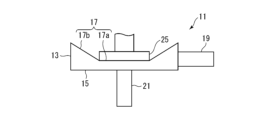
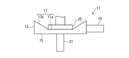
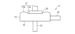
- the support portion 17b may be arranged to be curved in a convex shape protruding toward the first end wall 15 at the home position (described later) (see FIGS. 6A to 6C), and the support portion 17b may be arranged so as to be curved in a convex shape protruding in a direction away from the first end wall 15 (see FIGS. 7A to 7C).
- a push rod driven by an electric actuator is used as the drive unit 25, and the push rod pushes the movable part 17a of the diaphragm, and the support part supports the movable part 17a. 17b is deformed so that the movable portion 17a of the diaphragm can move relative to the first end wall 15.
- the drive section 25 is not limited to a push rod driven by an electric actuator as long as the movable section 17a can move relative to the first end wall 15.
- a push rod driven manually or by air may be used as the drive unit 25.
- the supporting portion 17b can be deformed by pressing the movable portion 17a of the diaphragm, it is also possible to use other mechanisms such as a piston cylinder as the driving portion 25.
- the inlet flow path 19 is provided so that the inlet flow path center axis P1 passes through an eccentric position away from the vortex chamber center axis O. Therefore, as shown in FIG. 4, the fluid flowing in from the inlet channel 19 generates a swirl flow in the vortex chamber 27 and swirls while heading toward the outlet channel 21 and flowing out from the outlet channel 21. do.
- the diaphragm, which is the second end wall 17, is located at the home position shown in FIG. 5A when it is not pressed by the drive unit 25. From this state, as shown in FIG. 5B, the second end wall 17 (the movable part 17a in the first embodiment) is pressed by the drive part 25, and the outlet flow path 21 is provided.
- the support portion 17b is elastically deformed by the pressing of the movable portion 17a by the drive portion 25, and the distance between the movable portion 17a and the first end wall 15 is at least becomes shorter.
- the area through which the fluid of the vortex generated in the vortex chamber 27 can pass becomes smaller, and the flow velocity of the vortex increases.
- the second end wall 17 when the second end wall 17 approaches the first end wall 15, the flow velocity increases and the pressure loss increases compared to the situation shown in FIG. 5A. As a result, the flow rate of fluid flowing out from the outlet channel 21 is reduced. From the state shown in FIG. 5B, the second end wall 17 (the movable part 17a in the first embodiment) is further pressed by the drive part 25, and as shown in FIG. As the end wall 15 is approached, the flow velocity of the vortex further increases, resulting in an even greater pressure loss. As a result, the flow rate of fluid exiting the outlet channel 21 is further reduced compared to the situation shown in FIG. 5B.
- the second end wall 17 is moved in the direction approaching the first end wall 15, thereby increasing the gap between the first end wall 15 and the second end wall 17.
- the pressure loss of the fluid flowing from the inlet channel 19 to the outlet channel 21 increases, and the flow rate of the fluid flowing out from the outlet channel 21 decreases. That is, by increasing the moving distance of the second end wall 17 in the direction approaching the first end wall 15 from the home position and reducing the area through which the fluid of the vortex generated in the vortex chamber 27 can pass. , the pressure loss of the fluid flowing from the inlet channel 19 to the outlet channel 21 increases, and the flow rate of the fluid flowing out from the outlet channel 21 can be reduced.
- the vortex flow control valve 11 if the gap between the first end wall 15 and the second end wall 17 can be changed, the flow rate of the fluid flowing out from the outlet channel 21 can be changed.
- the invention is not limited to the embodiments shown, as they may vary. That is, the vortex flow control valve 11 according to the present invention can be modified in a wide range of ways.
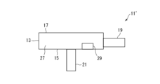
- the second end wall 17 only needs to be able to move toward and away from the first end wall 15 by deforming the support portion 17b when the movable portion 17a is pressed, and the position of the movable portion 17a also changes from the second end wall 17. It does not have to be in the center of the Further, as in the third embodiment of the swirl flow control valve 11' shown in FIG.
- the gap between the top of the protrusion 29 and the second end wall 17 may be changed by moving them closer to each other and away from each other.
- the second end wall 17' is movable along the circumferential wall 13, and the second end wall 17' is moved from the home position shown in FIG. 12(a) to the position shown in FIG. 12(b). By moving it along the circumferential wall 13, the gap between the first end wall 15 and the second end wall 17' may be changed.
- FIGS. 11 and 12 the same reference numerals are given to the same components as those of the swirl flow control valve 11 of the embodiment shown in FIG. Further, in the swirl type flow rate control valve 11' and the swirl type flow rate control valve 11'', the second end wall 17 or the second end wall 17' approaches and moves away from the first end wall 15 as shown in FIG. It is similar to the swirl flow control valve 11 of the illustrated embodiment, and the flow rate is adjusted by changing the distance (gap) between the first end wall 15 and the second end wall 17. Therefore, a detailed explanation of the configuration and operation will be omitted here.
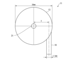
- the simulation is carried out in such a way that the vortex chamber 27 has a cylindrical shape with a diameter of 30 mm and a height of 7.5 mm, and the center of the inlet flow path, as shown in FIGS. 8A and 8B.
- an inlet channel 19 in the shape of a right circular tube with a diameter of 3.5 mm is connected to the peripheral side wall 13 so as to pass through a position 2.25 mm away from the first end wall 15, and has a diameter of 3.5 mm and a length of 10 mm.
- a circular tube-shaped outlet flow path 21 extends along the center axis O of the vortex chamber, and is connected to the first end wall 15 such that the outlet flow path center axis P2 passes through the center of the first end wall 15.
- the driving section 25 presses and moves a circular region having a diameter of 14 mm concentric with the end wall 17 of No. 2.
- the position of the inlet channel 19 with respect to the outlet channel 21 is determined by the center of the swirl chamber 27 ( That is, it was defined as the ratio (%) of the distance between the outlet flow path center axis P2 of the outlet flow path 21 and the inlet flow path center axis P1 of the inlet flow path 19. This is because the inlet channel 19 can be provided away from the center of the vortex chamber 27 only up to a position where the inlet channel center axis P1 is away from the circumferential wall 13 by the radius of the inlet channel 19. .
- the home position of the diaphragm is the position of the diaphragm when it is not pressed by the drive unit 25.
- the simulations were performed for various positions of the inlet channel 19 relative to the outlet channel 21.
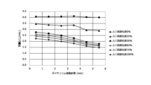
- FIG. 9 shows the diaphragm (No. 2 is a line graph plotting the relationship between the moving distance (mm) of the end wall 17) of No. 2 and the flow rate Q (L/min) of the fluid flowing out from the outlet flow path 21.
- the symbol “ ⁇ ” indicates that the position of the inlet channel 19 with respect to the outlet channel 21 is 0%
- the symbol “ ⁇ ” indicates that the position of the inlet channel 19 with respect to the outlet channel 21 is 25%.
- the diaphragm which is the second end wall 17, moves from the home position toward the first end wall 15, except when the inlet channel 19 is at the 0% position with respect to the outlet channel 21. It has been confirmed that the flow rate Q of the fluid flowing out from the outlet channel 21 decreases as the distance between the first end wall 15 and the second end wall 17 increases. This is because when the moving distance of the diaphragm from the home position becomes longer, the area through which the fluid can pass becomes narrower and the flow velocity increases, and when a vortex is generated in the vortex chamber 27, the flow from the inlet flow path 19 to the outlet flow path increases. This is presumed to be because the line becomes longer, so pressure loss tends to increase as the flow rate increases.
- the inlet flow path center axis P1 when the inlet flow path center axis P1 is in a positional relationship that does not intersect with the outlet flow path center axis P2, the fluid flowing in from the inlet flow path 19 collides with the circumferential wall 13 in the vortex chamber 27, and the circumferential wall 13 The water flows along the flow path, turns into a vortex, and heads toward the outlet flow path 21. Therefore, the length of the streamline from the inlet channel 19 to the outlet channel 21 becomes longer. Further, when the diaphragm, which is the second end wall 17, moves from the home position toward the first end wall 15, the distance between the first end wall 15 and the second end wall 17 becomes shorter, and the vortex chamber The flow velocity of the vortex flow in 27 increases and the pressure drop increases. As a result of this increase in pressure loss, the flow rate of fluid exiting the outlet channel 21 is reduced.
- the flow rate Q of the fluid flowing out from the outlet flow path 21 decreases as the inlet flow path 19 is provided so that the center axis P1 of the inlet flow path passes through a position farther from the center axis P2 of the outlet flow path.
- the inlet flow path 19 when the inlet flow path 19 is provided so that the inlet flow path center axis P1 passes through a position apart from the outlet flow path center axis P2, the movement of the second end wall 17 from the home position
- the flow rate Q of the fluid flowing out from the outlet channel 21 changes depending on the distance, and there is a correlation between the moving distance of the second end wall 17 from the home position and the flow rate Q. Therefore, by changing the moving distance of the second end wall 17 from the home position, the flow rate Q can be changed, and the flow rate Q can be adjusted and controlled.
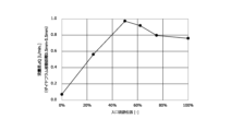
- the influence of the position of the inlet flow path 19 within the vortex chamber 27 was confirmed by simulation.
- the position of the inlet channel 19 with respect to the outlet channel 21 is 0%, 25%. %, 50%, 62%, 75%, and 100%.
- FIG. 10 shows the entrance to the outlet flow path 21 obtained by changing the moving distance of the diaphragm, which is the second end wall 17, in the direction from the home position toward the first end wall 15 from 0.5 mm to 5.5 mm. It is a line graph plotting the relationship between the position of the flow path 19 and the flow rate difference ⁇ Q (L/min). From FIG. 10, it can be seen that under the condition that the position of the outlet channel 21 is connected to the first end wall 15 so as to extend from the center of the vortex chamber 27, regardless of the position of the inlet channel 19 with respect to the outlet channel 21, It has been found that the flow rate difference ⁇ Q can be generated depending on the moving distance of the second end wall 17.
- the flow rate of the fluid flowing out from the outlet channel 21 can be adjusted by moving the second end wall 17 of the swirl flow control valve 11. be. It has also been found that the largest flow rate difference ⁇ Q is produced when the position of the inlet channel 19 with respect to the outlet channel 21 is 50%, making it possible to adjust the flow rate over a wider range. Therefore, when it is necessary to adjust the flow rate over a wide range, it is preferable to provide the inlet channel 19 so that the position of the inlet channel 19 is 50% with respect to the outlet channel 21.
- the vortex flow control valve according to the present invention has been described above with reference to the illustrated embodiments, the present invention is not limited to the illustrated embodiments.
- a cylindrical vortex chamber 27 is employed, but if a vortex can be generated within the vortex chamber 27, an elliptical or polygonal cylindrical vortex chamber may be employed. is also possible.
- the flow rate Q can be changed by moving the second end wall 17 with respect to the first end wall 15 and changing the gap, the flow rate Q of the third embodiment shown in FIG.
- the protrusion 29 may be provided on the first end wall 15 as shown in FIG.
- the distance between wall 15 and second end wall 17 may be varied.
Landscapes
- Engineering & Computer Science (AREA)
- General Engineering & Computer Science (AREA)
- Mechanical Engineering (AREA)
- Lift Valve (AREA)
Priority Applications (3)
| Application Number | Priority Date | Filing Date | Title |
|---|---|---|---|
| CN202380032617.9A CN119096074A (zh) | 2022-05-23 | 2023-05-22 | 涡流型流量调节阀 |
| JP2024523291A JPWO2023228916A1 (https=) | 2022-05-23 | 2023-05-22 | |
| KR1020247038194A KR20250016110A (ko) | 2022-05-23 | 2023-05-22 | 와류형 유량조절밸브 |
Applications Claiming Priority (2)
| Application Number | Priority Date | Filing Date | Title |
|---|---|---|---|
| JP2022-084138 | 2022-05-23 | ||
| JP2022084138 | 2022-05-23 |
Publications (1)
| Publication Number | Publication Date |
|---|---|
| WO2023228916A1 true WO2023228916A1 (ja) | 2023-11-30 |
Family
ID=88919283
Family Applications (1)
| Application Number | Title | Priority Date | Filing Date |
|---|---|---|---|
| PCT/JP2023/019010 Ceased WO2023228916A1 (ja) | 2022-05-23 | 2023-05-22 | 渦流型流量調節弁 |
Country Status (5)
| Country | Link |
|---|---|
| JP (1) | JPWO2023228916A1 (https=) |
| KR (1) | KR20250016110A (https=) |
| CN (1) | CN119096074A (https=) |
| TW (1) | TW202348905A (https=) |
| WO (1) | WO2023228916A1 (https=) |
Citations (2)
| Publication number | Priority date | Publication date | Assignee | Title |
|---|---|---|---|---|
| JPS51117332A (en) * | 1975-03-26 | 1976-10-15 | Canadian Patents Dev | Fluid flow quantity regulating device |
| JPS6291254A (ja) * | 1985-10-16 | 1987-04-25 | Shizuoka Seiki Co Ltd | 流量可変ノズルの流量制御機構 |
Family Cites Families (1)
| Publication number | Priority date | Publication date | Assignee | Title |
|---|---|---|---|---|
| JPS5144880U (https=) | 1974-09-30 | 1976-04-02 |
-
2023
- 2023-05-19 TW TW112118730A patent/TW202348905A/zh unknown
- 2023-05-22 KR KR1020247038194A patent/KR20250016110A/ko active Pending
- 2023-05-22 CN CN202380032617.9A patent/CN119096074A/zh active Pending
- 2023-05-22 WO PCT/JP2023/019010 patent/WO2023228916A1/ja not_active Ceased
- 2023-05-22 JP JP2024523291A patent/JPWO2023228916A1/ja active Pending
Patent Citations (2)
| Publication number | Priority date | Publication date | Assignee | Title |
|---|---|---|---|---|
| JPS51117332A (en) * | 1975-03-26 | 1976-10-15 | Canadian Patents Dev | Fluid flow quantity regulating device |
| JPS6291254A (ja) * | 1985-10-16 | 1987-04-25 | Shizuoka Seiki Co Ltd | 流量可変ノズルの流量制御機構 |
Also Published As
| Publication number | Publication date |
|---|---|
| KR20250016110A (ko) | 2025-02-03 |
| TW202348905A (zh) | 2023-12-16 |
| JPWO2023228916A1 (https=) | 2023-11-30 |
| CN119096074A (zh) | 2024-12-06 |
Similar Documents
| Publication | Publication Date | Title |
|---|---|---|
| US10427501B2 (en) | Outlet device | |
| KR101921523B1 (ko) | 전자 팽창 밸브 | |
| US11471898B2 (en) | Fluidic component | |
| RU2713319C2 (ru) | Клетка, подавляющая аэродинамический шум | |
| US7055798B2 (en) | Proportional solenoid control valve | |
| EP3366957B1 (en) | Electric valve | |
| KR102229998B1 (ko) | 유체 유동 제어 장치 및 시스템과 이들을 통해 유체를 유동시키는 방법 | |
| CN107940092B (zh) | 气体流量调节装置、风道组件和空调器 | |
| CN103629369B (zh) | 具有导流装置的阀装置 | |
| US20220296943A1 (en) | Nozzle with adjustable spray | |
| CN104976376B (zh) | 流路切换阀用阀芯 | |
| US20220297138A1 (en) | Smooth bore nozzle | |
| WO2023228915A1 (ja) | 渦流型流量調節弁 | |
| WO2023228916A1 (ja) | 渦流型流量調節弁 | |
| CN106286892B (zh) | 三通电磁阀 | |
| CN115003938A (zh) | 用于加热和/或冷却应用的膨胀阀 | |
| CN102834562A (zh) | 用于调节流体流的阀 | |
| KR20120048566A (ko) | 백래시 방지 장치를 갖는 조절기 밸브 조립체 | |
| CN112049972A (zh) | 用于控制过程流体流动的提升阀 | |
| JP6901123B2 (ja) | ドラフトコック | |
| RU2514328C1 (ru) | Дроссельно-регулирующее устройство | |
| WO2016135823A1 (ja) | 流体制御弁 | |
| JP2015052389A (ja) | 流体制御弁 | |
| US10852752B2 (en) | High flow low pressure control valve | |
| KR102697136B1 (ko) | 유량 조절밸브 |
Legal Events
| Date | Code | Title | Description |
|---|---|---|---|
| 121 | Ep: the epo has been informed by wipo that ep was designated in this application |
Ref document number: 23811788 Country of ref document: EP Kind code of ref document: A1 |
|
| ENP | Entry into the national phase |
Ref document number: 2024523291 Country of ref document: JP Kind code of ref document: A |
|
| WWE | Wipo information: entry into national phase |
Ref document number: 202380032617.9 Country of ref document: CN |
|
| WWE | Wipo information: entry into national phase |
Ref document number: 18868174 Country of ref document: US |
|
| NENP | Non-entry into the national phase |
Ref country code: DE |
|
| WWP | Wipo information: published in national office |
Ref document number: 1020247038194 Country of ref document: KR |
|
| 122 | Ep: pct application non-entry in european phase |
Ref document number: 23811788 Country of ref document: EP Kind code of ref document: A1 |