WO2023228798A1 - 伸縮デバイス - Google Patents
伸縮デバイス Download PDFInfo
- Publication number
- WO2023228798A1 WO2023228798A1 PCT/JP2023/018134 JP2023018134W WO2023228798A1 WO 2023228798 A1 WO2023228798 A1 WO 2023228798A1 JP 2023018134 W JP2023018134 W JP 2023018134W WO 2023228798 A1 WO2023228798 A1 WO 2023228798A1
- Authority
- WO
- WIPO (PCT)
- Prior art keywords
- electrode
- base material
- stretchable
- insulating layer
- stretchable base
- Prior art date
- Legal status (The legal status is an assumption and is not a legal conclusion. Google has not performed a legal analysis and makes no representation as to the accuracy of the status listed.)
- Ceased
Links
Images


Classifications
-
- H—ELECTRICITY
- H05—ELECTRIC TECHNIQUES NOT OTHERWISE PROVIDED FOR
- H05K—PRINTED CIRCUITS; CASINGS OR CONSTRUCTIONAL DETAILS OF ELECTRIC APPARATUS; MANUFACTURE OF ASSEMBLAGES OF ELECTRICAL COMPONENTS
- H05K1/00—Printed circuits
- H05K1/02—Details
- H05K1/0277—Bendability or stretchability details
- H05K1/028—Bending or folding regions of flexible printed circuits
-
- H—ELECTRICITY
- H05—ELECTRIC TECHNIQUES NOT OTHERWISE PROVIDED FOR
- H05K—PRINTED CIRCUITS; CASINGS OR CONSTRUCTIONAL DETAILS OF ELECTRIC APPARATUS; MANUFACTURE OF ASSEMBLAGES OF ELECTRICAL COMPONENTS
- H05K1/00—Printed circuits
- H05K1/02—Details
-
- H—ELECTRICITY
- H05—ELECTRIC TECHNIQUES NOT OTHERWISE PROVIDED FOR
- H05K—PRINTED CIRCUITS; CASINGS OR CONSTRUCTIONAL DETAILS OF ELECTRIC APPARATUS; MANUFACTURE OF ASSEMBLAGES OF ELECTRICAL COMPONENTS
- H05K1/00—Printed circuits
- H05K1/02—Details
- H05K1/0277—Bendability or stretchability details
- H05K1/0283—Stretchable printed circuits
-
- H—ELECTRICITY
- H05—ELECTRIC TECHNIQUES NOT OTHERWISE PROVIDED FOR
- H05K—PRINTED CIRCUITS; CASINGS OR CONSTRUCTIONAL DETAILS OF ELECTRIC APPARATUS; MANUFACTURE OF ASSEMBLAGES OF ELECTRICAL COMPONENTS
- H05K2201/00—Indexing scheme relating to printed circuits covered by H05K1/00
- H05K2201/03—Conductive materials
- H05K2201/0302—Properties and characteristics in general
- H05K2201/0311—Metallic part with specific elastic properties, e.g. bent piece of metal as electrical contact
-
- H—ELECTRICITY
- H05—ELECTRIC TECHNIQUES NOT OTHERWISE PROVIDED FOR
- H05K—PRINTED CIRCUITS; CASINGS OR CONSTRUCTIONAL DETAILS OF ELECTRIC APPARATUS; MANUFACTURE OF ASSEMBLAGES OF ELECTRICAL COMPONENTS
- H05K2201/00—Indexing scheme relating to printed circuits covered by H05K1/00
- H05K2201/03—Conductive materials
- H05K2201/0332—Structure of the conductor
- H05K2201/0388—Other aspects of conductors
- H05K2201/0391—Using different types of conductors
-
- H—ELECTRICITY
- H05—ELECTRIC TECHNIQUES NOT OTHERWISE PROVIDED FOR
- H05K—PRINTED CIRCUITS; CASINGS OR CONSTRUCTIONAL DETAILS OF ELECTRIC APPARATUS; MANUFACTURE OF ASSEMBLAGES OF ELECTRICAL COMPONENTS
- H05K2201/00—Indexing scheme relating to printed circuits covered by H05K1/00
- H05K2201/10—Details of components or other objects attached to or integrated in a printed circuit board
- H05K2201/10613—Details of electrical connections of non-printed components, e.g. special leads
- H05K2201/10742—Details of leads
- H05K2201/10886—Other details
- H05K2201/10909—Materials of terminal, e.g. of leads or electrodes of components
Definitions
- the present invention relates to a telescopic device.
- Patent Document 1 Japanese Patent No. 3518023
- This stretchable device includes a silver resin pattern provided on an insulating synthetic resin base material, an insulating resin resin provided on the silver resin pattern so as to expose a part of the silver resin pattern, A fluororesin thin film provided on the exposed portion of the silver resin pattern.
- an object of the present disclosure is to provide a stretchable device that can suppress migration.
- a telescopic device includes: A stretchable stretchable base material; A first electrode, a second electrode, and a third electrode provided on the stretchable base material,
- the ionization tendency of the conductive material that is the main component of the third electrode is smaller than the ionization tendency of the conductive material that is the main component of the first electrode and the ionization tendency of the conductive material that is the main component of the second electrode,
- the shortest distance between the first electrode and the third electrode is smaller than the shortest distance between the first electrode and the second electrode.
- FIG. 1 is a schematic perspective view partially showing a telescopic device according to a first embodiment of the present invention.
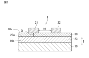
- FIG. 2 is a sectional view taken along line II-II in FIG.
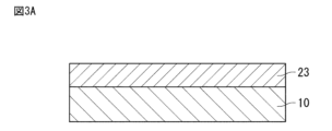
- FIG. 3A is an explanatory diagram illustrating a method for manufacturing a telescopic device.
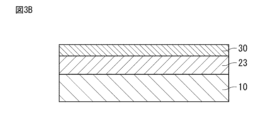
- FIG. 3B is an explanatory diagram illustrating a method for manufacturing a telescopic device.
- FIG. 3C is an explanatory diagram illustrating a method for manufacturing a telescopic device.
- FIG. 4A is a schematic cross-sectional view showing a telescopic device according to a second embodiment of the present invention.
- FIG. 4B is a schematic cross-sectional view showing a telescopic device according to a modification of the second embodiment of the present invention.
- FIG. 1 is a schematic perspective view partially showing a telescopic device according to a first embodiment of the present invention.
- FIG. 2 is a sectional view taken along line II-II in FIG.
- FIG. 5 is a schematic cross-sectional view showing a telescopic device according to a third embodiment of the present invention.
- FIG. 6 is a schematic cross-sectional view showing a telescopic device according to a fourth embodiment of the present invention.
- FIG. 7 is a schematic cross-sectional view showing a telescopic device according to a fifth embodiment of the present invention.
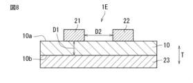
- FIG. 8 is a schematic cross-sectional view showing a telescopic device according to a sixth embodiment of the present invention.
- FIG. 9 is a schematic cross-sectional view showing a telescopic device according to a seventh embodiment of the present invention.
- FIG. 10 is a schematic cross-sectional view showing a telescopic device according to an eighth embodiment of the present invention.
- FIG. 10 is a schematic cross-sectional view showing a telescopic device according to an eighth embodiment of the present invention.
- FIG. 11A is a schematic cross-sectional view showing a telescopic device according to a ninth embodiment of the present invention.
- FIG. 11B is a schematic cross-sectional view showing a telescopic device according to a modification of the ninth embodiment of the present invention.
- FIG. 11C is a schematic cross-sectional view showing a telescopic device according to a modification of the ninth embodiment of the present invention.
- the present disclosure is particularly effective for circuit boards in which electrodes are formed on a base material that easily absorbs moisture, such as a stretchable base material, using a metal that easily causes migration (movement of metal ions), such as silver or copper. Migration can proceed from the positive electrode to the negative electrode.
- FIG. 1 is a schematic perspective view partially showing the telescopic device 1.
- FIG. 2 is a sectional view taken along line II-II in FIG.
- T the thickness direction of the stretchable base material
- the stretchable device 1 includes a stretchable stretchable base material 10, and a first electrode 21, a second electrode 22, and a third electrode 23 provided on the stretchable base material 10.
- the stretchable device 1 is, for example, attached to a living body and used to measure biological signals.
- on the stretchable base material does not refer to an absolute one direction such as vertically upward defined by the direction of gravity, but to the outside and inside of the stretchable base material with the surface of the stretchable base material as the boundary. It refers to the direction towards the outside. Therefore, “on the stretchable base material” is a relative direction determined by the orientation of the surface of the stretchable base material. Furthermore, “above” an element does not only mean a position directly above the element (on), but also a position above the element that is away from it, that is, a position above the element through other objects. Also includes spaced above positions.
- the stretchable base material 10 is a sheet-like or film-like base material made of a stretchable resin material.
- the resin material include thermoplastic polyurethane (TPU).
- TPU thermoplastic polyurethane
- the thickness of the stretchable base material 10 is not particularly limited, but from the viewpoint of not inhibiting the expansion and contraction of the surface of a living body when attached to a living body, it is preferably 1 mm or less, more preferably 100 ⁇ m or less, and 50 ⁇ m or less. It is more preferable that Moreover, it is preferable that the thickness of the elastic base material 10 is 1 ⁇ m or more.
- the shape of the stretchable base material 10 is not particularly limited. In this embodiment, the stretchable base material 10 is shaped to stretch in one direction when viewed from the thickness direction T.
- the first electrode 21 and the second electrode 22 are signal electrodes.
- the first electrode 21 and the second electrode 22 may be wiring.
- the shapes of the first electrode 21 and the second electrode 22 are not particularly limited.
- each of the first electrode 21 and the second electrode 22 is a wiring, and has a shape extending in one direction.
- a plurality of each of the first electrode 21 and the second electrode 22 may be provided. Further, the first electrode and the second electrode may not be provided on the same plane.
- the first electrode 21 and the second electrode 22 are formed of a conductive material. It is preferable that the first electrode 21 and the second electrode 22 have elasticity.
- the conductive material of the first electrode 21 and the second electrode 22 for example, metal foil such as silver, copper, or nickel may be used, and metal powder such as silver, copper, or nickel and epoxy resin, urethane resin, or acrylic resin may be used. and an elastomer resin such as a silicone resin may also be used.
- the electrically conductive material for the first electrode 21 and the second electrode 22 is preferably silver. Thereby, the first electrode 21 and the second electrode 22 with low resistance can be formed.
- the third electrode 23 is an electrode for suppressing migration.
- the third electrode 23 may be a wiring. A voltage for suppressing migration is applied to the third electrode 23 .
- the third electrode 23 may be used for signals in addition to migration suppression.
- the shape of the third electrode 23 is not particularly limited. In this embodiment, the third electrode 23 has a plate shape.
- the third electrode 23 may be a dummy electrode on which no signal is transmitted or received.
- the third electrode 23 is made of a conductive material. It is preferable that the third electrode 23 has elasticity. As the conductive material of the third electrode 23, a material having migration resistance (in other words, having a small ionization tendency), such as carbon or platinum, is used.
- the ionization tendency of the conductive material that is the main component of the third electrode 23 is smaller than the ionization tendency of the conductive material that is the main component of the first electrode 21 and the ionization tendency of the conductive material that is the main component of the second electrode 22.
- the "conductive material that is the main component” refers to the element that has the largest proportion (weight %) among the conductive elements contained in the electrode.
- both the first electrode 21 and the second electrode 22 can be silver electrodes
- the third electrode 23 can be a carbon electrode.
- the ionization tendency of the conductive material that is the main component of the third electrode 23, that is, carbon, is the same as the ionization tendency of the conductive material that is the main component of the first electrode 21, that is, silver, and the conductive material that is the main component of the second electrode 22. , that is, smaller than the ionization tendency of silver.
- the shortest distance D1 between the first electrode 21 and the third electrode 23 is smaller than the shortest distance D2 between the first electrode 21 and the second electrode 22.
- the shortest distance D1 refers to the minimum value of the distance between the first electrode 21 and the third electrode 23 in the opposing direction (in this embodiment, the thickness direction T of the stretchable base material 10).
- the shortest distance D2 refers to the minimum value of the distance between the first electrode 21 and the second electrode 22 in the opposing direction (in this embodiment, the left-right direction in FIG. 2).
- the shortest distance D1 and the shortest distance D2 may be measured on a cross section that is parallel to the thickness direction T of the stretchable base material 10 and intersects the first electrode 21, the second electrode 22, and the third electrode 23. In this embodiment, the shortest distance D1 and the shortest distance D2 may be measured, for example, on a cross section passing through the center of the first electrode 21 in the stretching direction and perpendicular to the stretching direction of the first electrode 21.
- the first electrode 21 and the third electrode 23 since the shortest distance D1 between the first electrode 21 and the third electrode 23 is smaller than the shortest distance D2 between the first electrode 21 and the second electrode 22, the first electrode 21 and the third electrode 23 The intensity of the electric field formed between the first electrode 21 and the second electrode 22 is greater than the intensity of the electric field formed between the first electrode 21 and the second electrode 22. Therefore, the force between the first electrode 21 and the third electrode 23 is greater than the force between the first electrode 21 and the second electrode 22. As a result, migration that may occur between the first electrode 21 and the second electrode 22 can be suppressed.
- the ionization tendency of the conductive material that is the main component of the third electrode 23 is smaller than the ionization tendency of the conductive material that is the main component of the first electrode 21 and the ionization tendency of the conductive material that is the main component of the second electrode 22. Therefore, even if the pulling force between the first electrode 21 and the third electrode 23 becomes larger than the pulling force between the first electrode 21 and the second electrode 22, the tension between the first electrode 21 and the third electrode 23 Migration that may occur between the two is suppressed. Thereby, migration that may occur in the elastic device 1 can be suppressed.
- the stretchable base material 10 has a first main surface 10a.
- the first electrode 21, the second electrode 22, and the third electrode 23 are provided on the first main surface 10a.
- the first electrode 21 and the second electrode 22 are arranged on the same plane.
- the third electrode 23 is arranged at a different position from the first electrode 21 and the second electrode 22 in the thickness direction T of the stretchable base material 10.
- the stretchable device 1 has an insulating layer 30 provided at least between the first electrode 21 and the third electrode 23 and between the second electrode 22 and the third electrode 23.
- on the first principal surface does not refer to an absolute direction such as vertically upward defined in the direction of gravity, but to the outside of the elastic substrate with the first principal surface of the elastic substrate as a boundary. It refers to the direction toward the outside of the inside. Therefore, “on the first main surface” is a relative direction determined by the orientation of the first main surface of the stretchable base material.
- the insulating layer 30 can suppress short circuits between the first electrode 21 and the third electrode 23 and between the second electrode 22 and the third electrode 23.
- the third electrode 23, the insulating layer 30, the first electrode 21, and the second electrode 22 are laminated in this order from the first main surface 10a side of the stretchable base material 10. According to this configuration, since the insulating layer 30 and the third electrode 23 are present between the first electrode 21 and the second electrode 22 and the stretchable base material 10, the first electrode 21 and the third electrode 23 are present from the stretchable base material 10 side. In addition, moisture can be prevented from entering the second electrode 22, and migration that may occur between the first electrode 21 and the second electrode 22 can be further suppressed.
- the third electrode 23 is provided on the entire first main surface 10a of the stretchable base material 10.
- the third electrode 23 is provided in a plate shape so as to cover the entire first main surface 10a of the stretchable base material 10.
- the insulating layer 30 is provided on the entire surface 23a of the third electrode 23 located on the side opposite to the stretchable base material 10 side.
- the surface 23a of the third electrode 23 corresponds to the surface located on the opposite side of the surface of the third electrode facing the stretchable base material 10.
- the insulating layer 30 is provided in a plate shape so as to cover the entire surface 23a of the third electrode 23.
- the first electrode 21 and the second electrode 22 are provided on a part of the surface 30a of the insulating layer 30 on the side opposite to the third electrode 23 side.
- the first electrode 21 extends along the stretching direction of the stretchable base material 10.
- the second electrode 22 extends along the stretching direction of the stretchable base material 10.
- the first electrode 21 and the second electrode 22 are separated by the shortest distance D2.
- the insulating layer 30 electrically insulates the first electrode 21, the second electrode 22, and the third electrode 23. It is preferable that the insulating layer 30 has elasticity.
- the insulating layer 30 may or may not be water absorbent.
- the shape of the insulating layer 30 is not particularly limited as long as it can electrically insulate the first electrode 21, the second electrode 22, and the third electrode 23.
- the insulating material of the insulating layer 30 is not particularly limited as long as it can electrically insulate the first electrode 21, the second electrode 22, and the third electrode 23.
- the insulating material of the insulating layer 30 is, for example, polyester resin.
- the polarity of the potential of the first electrode 21 is different from the polarity of the potential of the second electrode 22, and the polarity of the potential of the third electrode 23 is different from the polarity of the potential of the first electrode 21. According to this configuration, signals with different polarities can be extracted from the first electrode 21 and the second electrode 22.
- the first electrodes 21 and second electrodes 22 are arranged alternately along the direction perpendicular to the extending direction of the first electrodes 21, and
- the polarity of the potential of the first electrode 21 may be made different from the polarity of the potential of the second electrode 22, and the polarity of the potential of the third electrode 23 may be made different from the polarity of the potential of the first electrode 21.
- the polarity of the potential of the first electrode 21 is negative.
- the polarity of the potential of the second electrode 22 is positive
- the polarity of the potential of the third electrode 23 is positive.
- the first electrode 21 and the third electrode 23 since the shortest distance D1 between the first electrode 21 and the third electrode 23 is smaller than the shortest distance D2 between the first electrode 21 and the second electrode 22, the first electrode 21 and the third electrode 23 The intensity of the electric field formed between the first electrode 21 and the second electrode 22 is greater than the intensity of the electric field formed between the first electrode 21 and the second electrode 22. Therefore, according to the above configuration, positive ions are suppressed from moving from the second electrode 22 to the first electrode 21 via the insulating layer 30, and are generated between the first electrode 21 and the second electrode 22.
- the polarity of the potential of the third electrode is positive, movement of cations from the second electrode 22 to the third electrode 23 via the insulating layer 30 is suppressed.
- the ionization tendency of the conductive material that is the main component of the third electrode 23 is different from the ionization tendency of the conductive material that is the main component of the first electrode 21 and that of the conductive material that is the main component of the second electrode 22. Since the ionization tendency is smaller than the ionization tendency, the movement of cations from the third electrode 23 to the first electrode 21 via the insulating layer 30 is suppressed. As described above, according to the above configuration, migration that may occur in the telescopic device 1 can be further suppressed.
- the third electrode 23 when the third electrode 23 is not provided, when the polarity of the potential of the first electrode 21 is negative and the polarity of the potential of the second electrode 22 is positive, the cations are can be easily moved from the second electrode 22 to the first electrode 21 via the . As a result, migration may occur between the first electrode 21 and the second electrode 22. Furthermore, even when the third electrode 23 is provided, the ionization tendency of the conductive material that is the main component of the third electrode 23 is different from the ionization tendency of the conductive material that is the main component of the first electrode 21 and that of the second electrode 22.
- the ionization tendency is the same as or greater than the ionization tendency of the conductive material that is the main component, cations can easily move from the third electrode 23 to the first electrode 21 via the insulating layer 30. As a result, migration may occur between the first electrode 21 and the third electrode 23.
- the third electrode 23 overlaps the entire first electrode 21 when viewed from the thickness direction T of the stretchable base material 10. More preferably, the third electrode 23 overlaps the entire first electrode 21 when viewed from the thickness direction T of the stretchable base material 10, and the planar area of the third electrode 23 is larger than the planar area of the first electrode 21. According to this configuration, since the third electrode can be easily aligned, the third electrode 23 can be easily formed. Further, since the first electrode 21 is arranged directly above the third electrode 23, the shortest distance D1 between the first electrode 21 and the third electrode 23 can be made smaller, and the distance between the first electrode 21 and the second electrode 22 can be further suppressed.
- the third electrode 23 overlaps the entire first electrode 21 and the entire second electrode 22 when viewed from the thickness direction T of the stretchable base material 10. More preferably, the third electrode 23 is a third electrode that overlaps the entire first electrode 21 and the entire second electrode 22 and overlaps the entire first electrode 21 when viewed from the thickness direction T of the stretchable base material 10. 23 and a third electrode that overlaps the entire second electrode 22 are integral, and the planar area of the third electrode 23 is the combined planar area of the first electrode 21 and the second electrode 22. larger than According to this configuration, for example, the third electrode 23 can be formed in a plate shape so as to cover the entire first main surface 10a of the stretchable base material 10, and patterning of the third electrode 23 is not required. 23 can be easily formed. Further, since the first electrode 21 is arranged directly above the third electrode 23, the shortest distance D1 between the first electrode 21 and the third electrode 23 can be made smaller, and the distance between the first electrode 21 and the second electrode 22 can be further suppressed.
- a protective layer (not shown) is provided on the insulating layer 30 so as to cover the first electrode 21 and the second electrode 22.
- the protective layer is preferably made of a stretchable resin material, such as an ionomer resin, a polyester resin, a styrene resin, an olefin resin, an epoxy resin, a urethane resin, an acrylic resin, or a silicone resin. According to this configuration, the first electrode 21 and the second electrode 22 can be protected from the external environment. Further, the insulating layer 30 may be arranged to cover the first electrode 21 and the second electrode 22.
- FIGS. 3A, 3B, and 3C are explanatory diagrams illustrating a method for manufacturing the telescopic device 1.
- the process conditions, materials used, etc. of the telescopic device 1 are specifically shown, but the following is just an example of the manufacturing method of the telescopic device 1, and the manufacturing method of the telescopic device 1 is as follows. Not limited by process conditions and materials used.
- the third electrode 23 is formed on the stretchable base material 10 by, for example, screen printing.
- the stretchable base material 10 is, for example, thermoplastic polyurethane (TPU). Process conditions and materials used are as follows, for example.
- ⁇ Third electrode material DuPont carbon electrode 7105 ⁇ Stretchable base material: DUS605_6UVPT (50 ⁇ m thick) manufactured by Seedam ⁇ Printing plate: SP plate (mesh: #500, linear 18 ⁇ m, emulsion thickness 11 ⁇ m, inner size 280mm square), pattern area: 150 x 150mm ⁇ Printing conditions: Squeegee: Micro squeegee (rubber hardness: 70°), Squeegee pressure: 200N/160mm width, Squeegee speed: 150mm/s, Squeegee attack angle: 60°, Distance: 1.5mm ⁇ Drying conditions: Circulating oven 100°C x 30 minutes
- an insulating layer 30 is formed on the third electrode 23 by, for example, screen printing.
- Process conditions and materials used are as follows, for example.
- ⁇ Insulating layer material Henkel ELECTRODAG 452SS ⁇ Printing plate: SP plate (mesh: #352, linear 23 ⁇ m, emulsion thickness 17 ⁇ m, inner size 280mm square), pattern area: 150 x 150mm ⁇ Printing conditions: Squeegee: Micro squeegee (rubber hardness: 70°), Squeegee pressure: 200N/160mm width, Squeegee speed: 150mm/s, Squeegee attack angle: 70°, Distance: 1.5mm ⁇ Curing conditions: UV light irradiation; 500 mJ/cm 2 at i-ray (365 nm)
- the first electrode 21 and the second electrode 22 are formed on the insulating layer 30 by, for example, screen printing.
- Process conditions and materials used are as follows, for example.
- ⁇ Electrode material DuPont silver electrode 5064 ⁇ Printing plate: SP plate (mesh: #500, linear 18 ⁇ m, emulsion thickness 11 ⁇ m, inner size 280mm square), pattern area: 150 x 150mm ⁇ Printing conditions: Squeegee: Micro squeegee (rubber hardness: 70°), Squeegee pressure: 100N/160mm width, Squeegee speed: 150mm/s, Squeegee attack angle: 50°, Distance: 1.5mm ⁇ Drying conditions: Circulating oven 100°C x 30 minutes
- FIG. 4A corresponds to the II-II cross section in FIG.
- the elastic device 1A is different from the elastic device 1 according to the first embodiment in the shape of the insulating layer.
- the insulating layer 30A of the stretchable device 1A includes a first portion 31 provided between the first electrode 21 and the third electrode 23 and a second portion provided between the second electrode 22 and the third electrode 23. 32.
- the first portion 31 and the second portion 32 are separated from each other.
- the insulating layer 30A is divided into a first portion 31 and a second portion 32.
- the insulating layer 30A may be divided into three or more parts.
- the first portion 31 is provided between the first electrode 21 and the third electrode 23 and electrically insulates the first electrode 21 and the third electrode 23.
- the first portion 31 extends along the direction in which the first electrode 21 extends.
- the second portion 32 is provided between the second electrode 22 and the third electrode 23 and electrically insulates the second electrode 22 and the third electrode 23.
- the second portion 32 extends along the extending direction of the second electrode 22.
- the first portion 31 and the second portion 32 are separated from each other by a predetermined distance in the direction in which the first electrode 21 and the second electrode 22 face each other (the left-right direction in FIG. 4A).
- the path through which ions move within the insulating layer 30A can be cut off between the first electrode 21 and the second electrode 22. Therefore, migration that may occur between the first electrode 21 and the second electrode 22 can be further suppressed.
- the insulating layers 30A are arranged at intervals on the stretchable base material 10. This reduces the planar area of the insulating layer 30A compared to a case where the insulating layer is continuous, so that the influence that the insulating layer 30A may have on the stretchability of the stretchable device 1A can be further reduced. Therefore, according to the above structure, it is possible to obtain a stretchable device with better stretchability while suppressing migration with the insulating layer.
- the stretchable device can be attached to a living body, for example.
- the elastic device When used on such a living body, the elastic device may be required to have breathability in order to reduce discomfort such as stuffiness when the elastic device is worn. This may be achieved, for example, by using a breathable material for the stretchable base material 10.
- a material with low air permeability as the insulating layer. Therefore, when the insulating layer is disposed over the entire stretchable device 1A when viewed from the thickness direction T of the stretchable base material 10, the air permeability may be reduced.
- the stretchable device 1A includes a region on the stretchable base material 10A between the first portion 31 and the second portion 32 where the insulating layer 30A is not provided. Thereby, reduction in air permeability of the stretchable device due to the insulating layer can be suppressed. That is, a stretchable device with good air permeability can be realized while suppressing migration by the insulating layer.
- one continuous insulating layer 30 is formed over the entire stretchable device when viewed from the thickness direction T of the stretchable base material 10, whereas in the second embodiment, the insulation layer 30 has a small planar area.
- Multiple layers are provided. That is, in the stretchable device 1A of the second embodiment, the insulating layer 30A is divided into the first portion 31 and the second portion 32, so that the area of the continuously provided insulating layer can be reduced. As a result, the thickness of the insulating layer can be controlled more precisely than when one continuous insulating layer is provided over a wide area. Specifically, non-uniformity in the thickness of the insulating layer due to uneven printing or the like can be reduced, and a stretchable device 1A including the insulating layer 30A having a more uniform thickness can be provided.
- the thickness of the insulating layer 30A may correspond to the shortest distance D1 between the first electrode 21 and the third electrode 23. Since the insulating layer 30A has a uniform thickness as described above, the shortest distance D1 becomes more uniform between the first electrode 21 and the third electrode 23, so that migration can be suppressed more suitably.
- the protective layer 40 may exist in the space between the first part 31 and the second part 32 (see FIG. (See 4B). Thereby, migration that may occur between the first electrode 21 and the second electrode 22 can be further suppressed. Further, since the protective layer 40 is present so as to bite into the space between the first portion 31 and the second portion 32, the protective layer can be suitably held by an anchor effect. Thereby, peeling of the protective layer 40 from the stretchable device 1A can be suitably suppressed.
- FIG. 5 corresponds to the II-II cross section in FIG.
- the elastic device 1B is different from the elastic device 1 according to the first embodiment in the shape of the third electrode.
- the third electrode 23B of the stretchable device 1B has a shape corresponding to the shapes of the first electrode 21 and the second electrode 22.
- the third electrode 23B includes a first portion 231 shaped to correspond to the shape of the first electrode 21, a second portion 232 shaped to correspond to the shape of the second electrode 22, has. That is, the first portion 231 extends linearly along the extending direction of the first electrode 21.
- the second portion 232 extends linearly along the direction in which the second electrode 22 extends.
- the third electrode 23B is divided into a first portion 231 and a second portion 232.
- the first portion 231 overlaps with the first electrode 21 when viewed from the thickness direction T of the stretchable base material 10.
- the second portion 232 overlaps with the second electrode 22 when viewed from the thickness direction T of the stretchable base material 10.
- the third electrode 23B since the third electrode 23B is divided, the electric field formed between the first electrode 21 and the third electrode 23B is reduced compared to a case where the third electrode 23B is not divided. You can concentrate. Therefore, the force in which the first electrode 21 and the third electrode 23B are pulled together becomes even larger than the force in which the first electrode 21 and the second electrode 22 are pulled together. As a result, migration that may occur between the first electrode 21 and the second electrode 22 can be further suppressed. Moreover, since the planar area of the third electrode 23B can be made smaller compared to the case where the third electrode 23B is not divided, the stretchability of the stretchable device 1B can be improved.
- the stretchable device can use transparent or translucent materials for materials other than the electrodes (ie, the stretchable base material 10, the insulating layer 30, and/or the protective layer, etc.).
- the third electrode 23B does not cover the first main surface 10a of the transparent or translucent stretchable base material 10 over the front surface, and when viewed from the thickness direction T of the stretchable base material 10, the first electrode 21 or It is arranged in a region overlapping with the second electrode 22. That is, when viewed from the thickness direction T of the stretchable base material 10, the stretchable device has electrodes arranged only in a partial area of the first main surface 10a of the transparent or semitransparent stretchable base material 10.
- the stretchable device when viewed from the thickness direction T of the stretchable base material 10, can include a transparent or semitransparent region in a region that does not include an electrode. Thereby, it becomes possible to visually recognize the mounting position of the telescopic device through the transparent or semi-transparent region.
- the second portion 232 of the third electrode 23B is preferably provided in order to alleviate unevenness on the upper surface of the insulating layer 30 that may be caused by the third electrode 23B, but it may not be provided. In this case, since the electric field formed between the first electrode 21 and the third electrode 23B can be further concentrated, migration that may occur between the first electrode 21 and the second electrode 22 can be further suppressed. .
- FIG. 6 corresponds to the II-II cross section in FIG.
- the stretchable device 1C is different from the stretchable device 1 according to the first embodiment in the shape of the third electrode.
- the third electrode 23C of the stretchable device 1C does not overlap the first electrode 21 and the second electrode 22 when viewed from the thickness direction T of the stretchable base material 10. Specifically, the third electrode 23C is provided on a part of the first main surface 10a of the stretchable base material 10. The third electrode 23C extends linearly along the extending direction of the first electrode 21. The third electrode 23C is arranged between the first electrode 21 and the second electrode 22 when viewed from the thickness direction T of the stretchable base material 10.
- the first electrode 21, the third electrode 23, and the second electrode 22 are arranged along the direction perpendicular to the thickness direction T of the stretchable base material. Since they can be arranged alternately in a staggered manner, the elasticity of the elastic device 1C can be made uniform. In particular, as described above, when the insulating layer 30 is arranged to cover the first electrode 21 and the second electrode 22, the elasticity of the elastic device 1C can be made more uniform.
- the thickness of the insulating layer 30 can be reduced.
- the third electrodes 23C are arranged alternately so as not to overlap the first electrodes 21 and the second electrodes 22.
- the shortest distance D1 between the first electrode 21 and the third electrode 23C is suitably secured, and the distance between the insulating layer 30
- the thickness can be reduced.
- the insulating layer 30 covering the third electrode 23C is different from the case where the first electrode 21, the second electrode 22, and the third electrode 23C overlap in the thickness direction T (for example, the configuration shown in FIG. 5). and may have a smaller thickness. Thereby, the height of the telescopic device can be further reduced.
- the thickness of the insulating layer 30 in the stretched state may be smaller than the thickness of the insulating layer 30 in the non-stretched state in the cross-sectional view shown in FIG.
- the third electrode 23C does not overlap the first electrode 21 and the second electrode 22 when viewed from the thickness direction T of the stretchable base material 10
- the thickness of the insulating layer 30 is relatively reduced by stretching.
- contact between the electrodes can be suitably prevented.
- the cross-sectional area A3 of the third electrode 23C is equal to the cross-sectional area A1 of the first electrode 21. 105% or less. According to this configuration, the elasticity of the elastic device 1C can be improved. More preferably, the cross-sectional area A3 of the third electrode 23C is 100% or less of the cross-sectional area A1 of the first electrode 21.
- the cross-sectional area A3 of the third electrode 23C is the same as that of the second electrode 22. It is 105% or less of the cross-sectional area A2. More preferably, the cross-sectional area A3 of the third electrode 23C is 100% or less of the cross-sectional area A2 of the second electrode 22. The closer the cross-sectional areas of the first electrode 21, the second electrode 22, and the third electrode 23 are to the same, the more uniform the elasticity of the elastic device 1C can be.
- the cross-sectional area A3 of the third electrode 23C is equal to the cross-sectional area A1 of the first electrode 21.
- 10% or more of The cross-sectional area A3 of the third electrode 23C is more preferably 50% or more, and even more preferably 90% or more, of the cross-sectional area A1 of the first electrode 21. According to this configuration, the cross-sectional areas of the first electrode 21, the second electrode 22, and the third electrode 23 become nearly the same, and the stretchability of the stretchable device 1C can be made even more uniform.
- the cross-sectional area A3 of the third electrode 23C is the same as that of the second electrode 22. It is 10% or more of the cross-sectional area A2.
- the cross-sectional area A3 of the third electrode 23C is more preferably 50% or more, and even more preferably 90% or more, of the cross-sectional area A2 of the second electrode 22. If the cross-sectional area A3 of the third electrode 23C is too small, the effect of suppressing migration may be reduced. By setting the lower limit of the cross-sectional area A3 of the third electrode 23C as described above, migration that may occur between the first electrode 21 and the second electrode 22 can be effectively suppressed.
- FIG. 7 corresponds to the II-II cross section in FIG.
- the stretchable device 1D is different from the stretchable device 1 according to the first embodiment in the positional relationships among the first electrode, the second electrode, the insulating layer, and the third electrode.
- the first electrode 21 and the second electrode 22 are provided on the first main surface 10a of the stretchable base material 10.
- the insulating layer 30 is provided on the first main surface 10a of the stretchable base material 10 so as to cover the first electrode 21 and the second electrode 22.
- the third electrode 23 is provided on the surface 30a of the insulating layer 30 on the opposite side to the first main surface 10a side of the stretchable base material 10. Note that in this embodiment, the position where the third electrode 23 is provided is not particularly limited; for example, the third electrode 23 may be provided below the first electrode 21 and the second electrode 22. .
- the first electrode 21 and the second electrode 22 are covered with the insulating layer 30, the first electrode 21 is protected from moisture that may enter from the upper side of the elastic base material 10 (the upper side in FIG. 7). And the second electrode 22 can be protected. Further, when the third electrode 23 is provided on the surface 30a of the insulating layer 30, the patterns of the first electrode 21 and the second electrode 22 can be hidden by the third electrode 23. In such a configuration, the third electrode 23 can also serve as a protective layer for the first electrode 21 and the second electrode 22. For example, the third electrode 23 can serve as a protective layer that suppresses moisture from entering the stretchable device 1D from the third electrode 23 side (upper side in FIG. 7).
- FIG. 8 corresponds to the II-II cross section in FIG.
- the stretchable device 1E is different from the stretchable device 1 according to the first embodiment in that an insulating layer is not provided and the position where the third electrode is provided.
- the stretchable base material 10 has a first main surface 10a and a second main surface 10b facing each other, a first electrode 21 and a second electrode 22 are provided on the first main surface 10a, and a third electrode 23 is provided on the first main surface 10a. , are provided on the second main surface 10b.
- the insulating layer 30 is not provided because electrical insulation between the first electrode 21, the second electrode 22, and the third electrode 23 can be ensured by the elastic base material 10.
- the manufacturing process can be simplified and manufacturing costs can be reduced.
- the thickness of the stretchable device 1E is reduced as a whole, and the height of the stretchable device can be made lower.
- the shortest distance D1 between the first electrode 21 and the third electrode 23 corresponds to the thickness of the elastic base material 10. Therefore, by providing the first electrode 21 and the second electrode 22 on one main surface 10a of the elastic base material 10 and providing the third electrode 23 on the other main surface 10b, it is possible to Therefore, the first electrode 21 and the third electrode 23 can be evenly spaced apart.
- the third electrode 23 may be a gel electrode.
- the stretchable device can be easily attached to a living body or the like. That is, by using the third electrode 23 as a gel electrode, the third electrode 23 can function as an adhesive layer for attaching the elastic device to a living body or the like.
- the gel electrode is composed of a conductive gel material containing, for example, water, alcohol, a humectant, an electrolyte, and the like. Examples of such gel materials include hydrogels having adhesive properties.
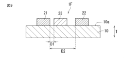
- FIG. 9 corresponds to the II-II cross section in FIG.
- the stretchable device 1F is different from the stretchable device 1 according to the first embodiment in that an insulating layer is not provided and the position where the third electrode is provided.
- the first electrode 21, the second electrode 22, and the third electrode 23 are provided on the same plane.
- the third electrode 23 is provided on the first main surface 10a of the stretchable base material 10, similarly to the first electrode 21 and the second electrode 22.
- the third electrode 23 extends linearly along the extending direction of the first electrode 21 .
- the third electrode 23 is arranged between the first electrode 21 and the second electrode 22.
- the third electrode 23 is spaced apart from each of the first electrode 21 and the second electrode 22.
- the insulating layer 30 is not provided.
- the manufacturing process can be simplified and manufacturing costs can be reduced. Furthermore, since it is not necessary to provide the insulating layer 30, the elastic device 1F can be made thinner.
- the third electrode 23 can prevent the bleeding of the second electrode 22 from reaching the first electrode 21 during printing. can be suitably suppressed.
- the third electrode 23 can also contribute to suppressing printing blur of the second electrode 22. Therefore, according to the above configuration, the distance D2 between the first electrode 21 and the second electrode 22 can be made smaller, and the expansion/contraction device can be made more compact.
- the first electrode 21, the second electrode 23, and the third electrode 23 can be arranged by controlling the printing pattern on the first main surface 10a.
- the distance D1 between the first electrode 21 and the third electrode 23, and the distance D2 between the first electrode 21 and the second electrode 22 can be more easily controlled.
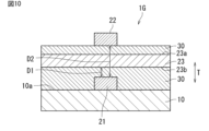
- FIG. 10 corresponds to the II-II cross section in FIG.
- the stretchable device 1G is different from the stretchable device 1 according to the first embodiment in that a first electrode 21 and a second electrode 22 are stacked with a third electrode 23 and an insulating layer 30 interposed therebetween. .
- the first electrode 21 and the second electrode 22 are stacked with the third electrode 23 in between.
- the first electrode 21 is provided on the first main surface 10a of the stretchable base material 10.
- the insulating layer 30 is provided on the first main surface 10a of the stretchable base material 10 so as to cover the first electrode 21.
- the third electrode 23 is arranged so as to face the first electrode 21 with the insulating layer 30 in between, on a surface 23b (hereinafter also referred to as second surface 23b) of the stretchable base material 10 that faces the first main surface 10a.
- An insulating layer 30 is further provided on a surface 23a (hereinafter also referred to as first surface 23a) of the third electrode 23 located on the opposite side to the second surface 23b.
- the second electrode 22 is arranged on the insulating layer 30 located on the first surface 23a.
- the insulating layer is provided between the first electrode 21 and the third electrode 23 and between the second electrode 22 and the third electrode 23. That is, the third electrode 23 includes the insulating layer 30 on both surfaces of the second surface 23b facing the first main surface of the stretchable base material 10 and the first surface 23a opposite to the second surface 23b. In other words, the third electrode 23 is located between the two insulating layers 30.
- the stretchable device 1G has a structure in which the first electrode 21, the insulating layer 30, the third electrode 23, the insulating layer 30, and the second electrode 22 are laminated in this order on the stretchable base material 10.
- first electrode 21 and the second electrode 22 may be reversed. That is, the second electrode 22 may be located between the stretchable base material 10 and the third electrode 23, and the first electrode 22 may be located on the first surface 23a side of the third electrode.
- the above configuration since the first electrode 21 and the second electrode 22 are physically separated by the third electrode 23, migration between the first electrode 21 and the second electrode 22 can be more preferably prevented. . Furthermore, as described above, the ionization tendency of the conductive material that is the main component of the third electrode 23 is smaller than the ionization tendency of the conductive material that is the main component of the first electrode 21 and the second electrode 22. Ion movement between 21 and third electrode 23 is suppressed. Therefore, the above configuration can provide a telescopic device 1G that can suppress the occurrence of migration.
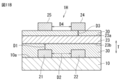
- a telescopic device 1H according to the ninth embodiment will be described below with reference to FIGS. 11A to 11C.
- 11A to 11C correspond to the II-II cross section in FIG. 1, respectively.
- the elastic device 1H is different from the elastic device 1 according to the first embodiment in that in addition to the first electrode 21 and the second electrode 22, a fourth electrode 24 and a fifth electrode 25 are further arranged. do.
- the first electrode 21 and the second electrode 24 are located on the same plane. That is, the first electrode 21 and the second electrode 22 are provided on the first main surface 10a of the stretchable base material 10.
- the insulating layer 30 is provided on the first main surface 10a of the stretchable base material 10 so as to cover the first electrode 21 and the second electrode 22.
- the third electrode 23 is provided on the second surface 23b side so as to face the first electrode 21 and the second electrode 22 with the insulating layer 30 in between.
- a fourth electrode 24 and a fifth electrode 25 are arranged on the insulating layer located on the first surface 23a side of the third electrode 23.
- the fourth electrode 24 and the fifth electrode 25 may be located on the same plane.
- the fourth electrode 24 and the fifth electrode 25 are arranged to face the first surface 23a of the third electrode 23 with the insulating layer 30 in between.
- the first electrode 21 and the second electrode 22, and the fourth electrode 24 and the fifth electrode 25 are stacked with the insulating layer 30 and the third electrode 23 in between.
- the ionization tendency of the conductive material that is the main component of the third electrode 23 is smaller than the ionization tendency of the conductive material that is the main component of the fourth electrode 24 and the ionization tendency of the conductive material that is the main component of the fifth electrode 25.
- both the fourth electrode 24 and the fifth electrode 25 can be silver electrodes
- the third electrode 23 can be a carbon electrode.
- the ionization tendency of the conductive material that is the main component of the third electrode 23, that is, carbon is the same as the ionization tendency of the conductive material that is the main component of the fourth electrode 24, that is, silver, and the conductive material that is the main component of the fifth electrode 25. , that is, smaller than the ionization tendency of silver.
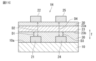
- the shortest distance D3 between the fourth electrode 24 and the third electrode 23 is smaller than the shortest distance D4 between the fourth electrode 24 and the fifth electrode 25.
- the shortest distance D3 refers to the minimum value of the distance between the fourth electrode 24 and the third electrode 23 in the opposing direction (in this embodiment, the thickness direction T of the stretchable base material 10).
- the shortest distance D4 refers to the minimum value of the distance between the fourth electrode 24 and the fifth electrode 25 in the opposing direction (in this embodiment, the left-right direction in FIG. 2).
- the shortest distance D3 and the shortest distance D4 may be measured on a cross section that is parallel to the thickness direction T of the stretchable base material 10 and intersects the fourth electrode 24, the fifth electrode 25, and the third electrode 23. In this embodiment, the shortest distance D3 and the shortest distance D4 may be measured, for example, on a cross section passing through the center of the fourth electrode 24 in the stretching direction and perpendicular to the stretching direction of the fourth electrode 24.
- the shortest distance D3 between the fourth electrode 24 and the third electrode 23 is smaller than the shortest distance D4 between the fourth electrode 24 and the fifth electrode 25.
- the intensity of the electric field formed between the fourth electrode 24 and the fifth electrode 25 is greater than the intensity of the electric field formed between the fourth electrode 24 and the fifth electrode 25. Therefore, ion movement between the fourth electrode 24 and the fifth electrode 25 is suppressed, and as a result, migration between the fourth electrode 24 and the fifth electrode 25 can be suppressed.
- the ionization tendency of the conductive material that is the main component of the third electrode 23 is smaller than the ionization tendency of the conductive material that is the main component of the fourth electrode 24 and the ionization tendency of the conductive material that is the main component of the fifth electrode 25. Therefore, migration that may occur between the fourth electrode 24 and the third electrode 23 is also suppressed. Thereby, migration that may occur in the elastic device 1 can be suppressed.
- a plurality of electrodes can be stacked and arranged while preventing migration between the electrodes by the third electrode 23.
- the area of the expansion/contraction device can be reduced compared to a structure in which a plurality of electrodes are arranged on the same plane. Therefore, a more compact telescopic device can be obtained.
- the polarity of the potential of the first to fifth electrodes is such that while the first electrode 21 and the fourth electrode 24 have the same potential polarity, the polarity of the potential of the second electrode 22, the third electrode 23, and the fifth electrode is different from the potential polarity. Electrodes 25 may have the same potential polarity. For example, the polarity of the potentials of the first electrode 21 and the fourth electrode 24 may be negative, and the polarity of the potentials of the second electrode 22, the third electrode 23, and the fifth electrode 25 may be positive. According to the above configuration, the presence of the third electrode 23 suppresses the movement of metal ions from the second electrode 22 and the fifth electrode 25 having positive polarity. Therefore, even in a stacked stretchable device including a plurality of electrodes, the occurrence of migration can be suitably suppressed.
- the arrangement of the first electrode 21, second electrode 22, fourth electrode 24, and fifth electrode 25 shown in FIG. 8 is mutually interchangeable. Simply put, the first electrode 21, the second electrode 22, the fourth electrode 24, and the fifth electrode 25 are compatible in terms of arrangement.
- the arrangement of the fourth electrode 24 and the arrangement of the fifth electrode 25 may be reversed compared to the stretchable device 1H of FIG. 11A. That is, electrodes having the same potential polarity may be arranged to face each other with the third electrode 23 in between, or alternatively, electrodes having different potential polarities may be arranged to face each other with the third electrode 23 in between. They may be arranged to face each other with 23 in between.
- the arrangement of the second electrode 22 and the arrangement of the fourth electrode 24 may be reversed compared to the stretchable device 1H of FIG. 11A.
- the first electrode 21 and the fourth electrode 24, which have the same potential polarity, are located on the same plane, and the potential polarity is the same on the opposite side of the third electrode 23.
- the second electrode 22 and the fifth electrode 25 may be located on the same plane.
- a plurality of electrodes with the same potential polarity are arranged on the same plane, and electrodes with different potential polarities are arranged so as to face each other with the third electrode 23 in between. It's fine.
- the ion movement path between the first electrode 21 and the second electrode 22 and the fourth electrode 24 and the fifth electrode 25 is physically blocked by the third electrode 23.
- the presence of the third electrode 23 prevents ion movement across the third electrode 23, so that the occurrence of migration can be suppressed more suitably.
- each embodiment is an example, and the present invention is not limited to each embodiment.
- each drawing is an illustration of the constituent elements, and does not limit the shape.
- partial substitution or combination of the configurations shown in different embodiments is possible.
- a stretchable stretchable base material A first electrode, a second electrode, and a third electrode provided on the stretchable base material,
- the ionization tendency of the conductive material that is the main component of the third electrode is smaller than the ionization tendency of the conductive material that is the main component of the first electrode and the ionization tendency of the conductive material that is the main component of the second electrode,
- the shortest distance between the first electrode and the third electrode is smaller than the shortest distance between the first electrode and the second electrode.
- the elastic device wherein the first electrode has a negative potential polarity.
- the stretchable base material has a first main surface, The first electrode, the second electrode, and the third electrode are provided on the first main surface, the first electrode and the second electrode are arranged on the same plane, The third electrode is arranged at a different position from the first electrode and the second electrode in the thickness direction of the stretchable base material, Any one of ⁇ 1> to ⁇ 3>, further comprising an insulating layer provided at least between the first electrode and the third electrode and between the second electrode and the third electrode.
- the elastic device according to ⁇ 4> wherein the third electrode, the insulating layer, the first electrode, and the second electrode are laminated in this order from the first main surface side.
- the insulating layer includes a first portion provided between the first electrode and the third electrode, and a second portion provided between the second electrode and the third electrode.
- the first electrode, the second electrode, the insulating layer, and the third electrode are stacked in any one of ⁇ 4> to ⁇ 6> in this order from the first main surface side. Telescoping device as described.
- the stretchable base material has a first main surface and a second main surface facing each other, The first electrode and the second electrode are provided on the first main surface, The elastic device according to any one of ⁇ 1> to ⁇ 3>, wherein the third electrode is provided on the second main surface.
- the third electrode overlaps the entire first electrode and the entire second electrode when viewed from the thickness direction of the elastic base material.
- ⁇ 11> The stretchable device according to any one of ⁇ 1> to ⁇ 8>, wherein the third electrode does not overlap the first electrode and the second electrode when viewed from the thickness direction of the stretchable base material.
- ⁇ 12> In a cross section that is parallel to the thickness direction of the stretchable base material and intersects the first electrode and the third electrode, the cross-sectional area of the third electrode is 105% or less of the cross-sectional area of the first electrode.
- the telescopic device according to any one of ⁇ 1> to ⁇ 11>.
- the first electrode and the second electrode are stacked with the third electrode in between, As described in any one of ⁇ 1> to ⁇ 3>, further comprising an insulating layer provided between the first electrode and the third electrode and between the second electrode and the third electrode.
- telescopic device As described in any one of ⁇ 1> to ⁇ 3>, further comprising an insulating layer provided between the first electrode and the third electrode and between the second electrode and the third electrode.
- ⁇ 14> Further comprising a fourth electrode and a fifth electrode provided on the stretchable base material,
- the ionization tendency of the conductive material that is the main component of the third electrode is smaller than the ionization tendency of the conductive material that is the main component of the fourth electrode and the ionization tendency of the conductive material that is the main component of the fifth electrode
- the telescopic device according to any one of ⁇ 1> to ⁇ 3>, wherein the shortest distance between the fourth electrode and the third electrode is smaller than the shortest distance between the fourth electrode and the fifth electrode.
- the polarity of the potential of the first electrode is the same as the polarity of the potential of the fourth electrode
- the first electrode and the second electrode are arranged on the same plane
- the fourth electrode and the fifth electrode are arranged on the same plane
- the stretchable base material, the first electrode and the second electrode, the third electrode, the fourth electrode and the fifth electrode are laminated in this order, ⁇ 14> or ⁇ 15>, comprising an insulating layer provided between the first electrode, the second electrode, and the third electrode, and between the fourth electrode, the fifth electrode, and the third electrode.
- the first electrode and the fourth electrode are arranged on the same plane
- the second electrode and the fifth electrode are arranged on the same plane
- the stretchable base material, the first electrode and the fourth electrode, the third electrode, the second electrode and the fifth electrode are laminated in this order, ⁇ 14> or ⁇ 15>, comprising an insulating layer provided between the first electrode, the fourth electrode, and the third electrode, and between the second electrode, the fifth electrode, and the third electrode.
- Stretchable device 10 Stretchable base material 10a: First main surface 10b: Second main surface 21: First electrode 22: Second electrode 23, 23B, 23C: First 3 electrodes 231: First portion 232: Second portion 30, 30A: Insulating layer 40: Protective layer A1, A2, A3: Cross-sectional area D1, D2: Shortest distance T: Thickness direction of elastic base material
Landscapes
- Engineering & Computer Science (AREA)
- Microelectronics & Electronic Packaging (AREA)
- Measurement And Recording Of Electrical Phenomena And Electrical Characteristics Of The Living Body (AREA)
Priority Applications (2)
| Application Number | Priority Date | Filing Date | Title |
|---|---|---|---|
| JP2024523047A JP7622905B2 (ja) | 2022-05-26 | 2023-05-15 | 伸縮デバイス |
| US18/955,236 US20250089159A1 (en) | 2022-05-26 | 2024-11-21 | Stretchable device |
Applications Claiming Priority (2)
| Application Number | Priority Date | Filing Date | Title |
|---|---|---|---|
| JP2022086226 | 2022-05-26 | ||
| JP2022-086226 | 2022-05-26 |
Related Child Applications (1)
| Application Number | Title | Priority Date | Filing Date |
|---|---|---|---|
| US18/955,236 Continuation US20250089159A1 (en) | 2022-05-26 | 2024-11-21 | Stretchable device |
Publications (1)
| Publication Number | Publication Date |
|---|---|
| WO2023228798A1 true WO2023228798A1 (ja) | 2023-11-30 |
Family
ID=88919208
Family Applications (1)
| Application Number | Title | Priority Date | Filing Date |
|---|---|---|---|
| PCT/JP2023/018134 Ceased WO2023228798A1 (ja) | 2022-05-26 | 2023-05-15 | 伸縮デバイス |
Country Status (3)
| Country | Link |
|---|---|
| US (1) | US20250089159A1 (https=) |
| JP (1) | JP7622905B2 (https=) |
| WO (1) | WO2023228798A1 (https=) |
Citations (5)
| Publication number | Priority date | Publication date | Assignee | Title |
|---|---|---|---|---|
| JPH11297218A (ja) * | 1998-04-13 | 1999-10-29 | Hitachi Ltd | プラズマディスプレイパネルの電極構造 |
| JP2005123419A (ja) * | 2003-10-17 | 2005-05-12 | Tohoku Pioneer Corp | 配線基板、配線パターンの形成方法、有機elパネル |
| US20110272181A1 (en) * | 2010-05-07 | 2011-11-10 | Samsung Electronics Co., Ltd. | Multilayer Stretchable Cable |
| US20150131239A1 (en) * | 2013-10-17 | 2015-05-14 | Korea University Research And Business Foundation | Three Dimensional Stretchable Electronic Device and Manufacturing Method Comprising the Same |
| WO2021235282A1 (ja) * | 2020-05-21 | 2021-11-25 | 株式会社村田製作所 | 伸縮性配線基板 |
Family Cites Families (1)
| Publication number | Priority date | Publication date | Assignee | Title |
|---|---|---|---|---|
| JP4038050B2 (ja) * | 2002-01-11 | 2008-01-23 | アルプス電気株式会社 | プリント配線基板の製造方法 |
-
2023
- 2023-05-15 WO PCT/JP2023/018134 patent/WO2023228798A1/ja not_active Ceased
- 2023-05-15 JP JP2024523047A patent/JP7622905B2/ja active Active
-
2024
- 2024-11-21 US US18/955,236 patent/US20250089159A1/en active Pending
Patent Citations (5)
| Publication number | Priority date | Publication date | Assignee | Title |
|---|---|---|---|---|
| JPH11297218A (ja) * | 1998-04-13 | 1999-10-29 | Hitachi Ltd | プラズマディスプレイパネルの電極構造 |
| JP2005123419A (ja) * | 2003-10-17 | 2005-05-12 | Tohoku Pioneer Corp | 配線基板、配線パターンの形成方法、有機elパネル |
| US20110272181A1 (en) * | 2010-05-07 | 2011-11-10 | Samsung Electronics Co., Ltd. | Multilayer Stretchable Cable |
| US20150131239A1 (en) * | 2013-10-17 | 2015-05-14 | Korea University Research And Business Foundation | Three Dimensional Stretchable Electronic Device and Manufacturing Method Comprising the Same |
| WO2021235282A1 (ja) * | 2020-05-21 | 2021-11-25 | 株式会社村田製作所 | 伸縮性配線基板 |
Also Published As
| Publication number | Publication date |
|---|---|
| US20250089159A1 (en) | 2025-03-13 |
| JP7622905B2 (ja) | 2025-01-28 |
| JPWO2023228798A1 (https=) | 2023-11-30 |
Similar Documents
| Publication | Publication Date | Title |
|---|---|---|
| JP5646433B2 (ja) | 導電シート及びその製造方法 | |
| JP5656599B2 (ja) | スイッチユニット | |
| JP4365844B2 (ja) | 荷電粒子線の線量分布測定装置 | |
| EP2824546A1 (en) | Flexible touch panel | |
| CN108093602A (zh) | 显示设备 | |
| WO2015088453A1 (en) | Touch screen for underwater use | |
| JP2008181709A (ja) | 操作スイッチ用シート部材及び操作スイッチ | |
| GB2077508A (en) | Variable resistance pressure- sensitive laminate | |
| WO2023228798A1 (ja) | 伸縮デバイス | |
| JP4147641B2 (ja) | メンブレンスイッチ | |
| CN109892031B (zh) | 屏蔽罩用电磁波屏蔽片 | |
| JP7584357B2 (ja) | ストレッチャブルデバイス及びその製造方法 | |
| WO2020153044A1 (ja) | 伸縮性配線基板 | |
| JPWO2020195544A1 (ja) | 伸縮性実装基板 | |
| JP2002033556A (ja) | 可撓性回路基板 | |
| KR100838544B1 (ko) | 판 스프링이 부착된 시트, 및 이 판 스프링이 부착된시트를 사용한 스위치 장치 | |
| US11804342B2 (en) | Membrane switch, key and keyboard | |
| GB2037079A (en) | Modular keyboard | |
| TWI689958B (zh) | 開關 | |
| WO2026048693A1 (ja) | 伸縮性デバイス | |
| JP4317806B2 (ja) | 接点構造 | |
| JP2006173025A (ja) | キー入力装置及びキー入力装置の操作圧の抑制方法 | |
| JPH023233Y2 (https=) | ||
| US20200273637A1 (en) | Switch and method for manufacturing same | |
| CN118511655A (zh) | 伸缩布线基板 |
Legal Events
| Date | Code | Title | Description |
|---|---|---|---|
| 121 | Ep: the epo has been informed by wipo that ep was designated in this application |
Ref document number: 23811672 Country of ref document: EP Kind code of ref document: A1 |
|
| WWE | Wipo information: entry into national phase |
Ref document number: 2024523047 Country of ref document: JP |
|
| NENP | Non-entry into the national phase |
Ref country code: DE |
|
| 122 | Ep: pct application non-entry in european phase |
Ref document number: 23811672 Country of ref document: EP Kind code of ref document: A1 |