WO2023228798A1 - Expansion/contraction device - Google Patents
Expansion/contraction device Download PDFInfo
- Publication number
- WO2023228798A1 WO2023228798A1 PCT/JP2023/018134 JP2023018134W WO2023228798A1 WO 2023228798 A1 WO2023228798 A1 WO 2023228798A1 JP 2023018134 W JP2023018134 W JP 2023018134W WO 2023228798 A1 WO2023228798 A1 WO 2023228798A1
- Authority
- WO
- WIPO (PCT)
- Prior art keywords
- electrode
- base material
- stretchable
- insulating layer
- stretchable base
- Prior art date
Links
- 230000008602 contraction Effects 0.000 title claims abstract description 8
- 239000000463 material Substances 0.000 claims abstract description 129
- 239000004020 conductor Substances 0.000 claims abstract description 50
- 238000000034 method Methods 0.000 claims description 12
- 239000010410 layer Substances 0.000 description 96
- 230000005012 migration Effects 0.000 description 42
- 238000013508 migration Methods 0.000 description 42
- BQCADISMDOOEFD-UHFFFAOYSA-N Silver Chemical compound [Ag] BQCADISMDOOEFD-UHFFFAOYSA-N 0.000 description 18
- 229910052709 silver Inorganic materials 0.000 description 18
- 239000004332 silver Substances 0.000 description 18
- 230000002829 reductive effect Effects 0.000 description 14
- 229920005989 resin Polymers 0.000 description 14
- 239000011347 resin Substances 0.000 description 14
- 239000011241 protective layer Substances 0.000 description 13
- 238000004519 manufacturing process Methods 0.000 description 12
- 238000007639 printing Methods 0.000 description 10
- 230000005684 electric field Effects 0.000 description 8
- OKTJSMMVPCPJKN-UHFFFAOYSA-N Carbon Chemical compound [C] OKTJSMMVPCPJKN-UHFFFAOYSA-N 0.000 description 6
- 229910052799 carbon Inorganic materials 0.000 description 6
- 239000000499 gel Substances 0.000 description 6
- 150000002500 ions Chemical class 0.000 description 6
- 229920002803 thermoplastic polyurethane Polymers 0.000 description 6
- 230000008569 process Effects 0.000 description 5
- RYGMFSIKBFXOCR-UHFFFAOYSA-N Copper Chemical compound [Cu] RYGMFSIKBFXOCR-UHFFFAOYSA-N 0.000 description 4
- PXHVJJICTQNCMI-UHFFFAOYSA-N Nickel Chemical compound [Ni] PXHVJJICTQNCMI-UHFFFAOYSA-N 0.000 description 4
- 239000004433 Thermoplastic polyurethane Substances 0.000 description 4
- 150000001768 cations Chemical class 0.000 description 4
- 229910052802 copper Inorganic materials 0.000 description 4
- 239000010949 copper Substances 0.000 description 4
- 238000010586 diagram Methods 0.000 description 4
- 229920001971 elastomer Polymers 0.000 description 4
- 230000035699 permeability Effects 0.000 description 4
- 230000000694 effects Effects 0.000 description 3
- 239000000839 emulsion Substances 0.000 description 3
- 229910052751 metal Inorganic materials 0.000 description 3
- 239000002184 metal Substances 0.000 description 3
- 230000004048 modification Effects 0.000 description 3
- 238000012986 modification Methods 0.000 description 3
- 238000007650 screen-printing Methods 0.000 description 3
- 239000000758 substrate Substances 0.000 description 3
- 229920000178 Acrylic resin Polymers 0.000 description 2
- 239000004925 Acrylic resin Substances 0.000 description 2
- PPBRXRYQALVLMV-UHFFFAOYSA-N Styrene Chemical compound C=CC1=CC=CC=C1 PPBRXRYQALVLMV-UHFFFAOYSA-N 0.000 description 2
- 238000001035 drying Methods 0.000 description 2
- 239000007772 electrode material Substances 0.000 description 2
- 239000003822 epoxy resin Substances 0.000 description 2
- 230000005484 gravity Effects 0.000 description 2
- 239000011810 insulating material Substances 0.000 description 2
- 229910021645 metal ion Inorganic materials 0.000 description 2
- 229910052759 nickel Inorganic materials 0.000 description 2
- 230000036961 partial effect Effects 0.000 description 2
- BASFCYQUMIYNBI-UHFFFAOYSA-N platinum Chemical compound [Pt] BASFCYQUMIYNBI-UHFFFAOYSA-N 0.000 description 2
- 229920000647 polyepoxide Polymers 0.000 description 2
- 229920001225 polyester resin Polymers 0.000 description 2
- 239000004645 polyester resin Substances 0.000 description 2
- 229920002050 silicone resin Polymers 0.000 description 2
- XLYOFNOQVPJJNP-UHFFFAOYSA-N water Substances O XLYOFNOQVPJJNP-UHFFFAOYSA-N 0.000 description 2
- LFQSCWFLJHTTHZ-UHFFFAOYSA-N Ethanol Chemical compound CCO LFQSCWFLJHTTHZ-UHFFFAOYSA-N 0.000 description 1
- 230000002745 absorbent Effects 0.000 description 1
- 239000002250 absorbent Substances 0.000 description 1
- 230000001070 adhesive effect Effects 0.000 description 1
- 239000012790 adhesive layer Substances 0.000 description 1
- 230000000740 bleeding effect Effects 0.000 description 1
- 239000012141 concentrate Substances 0.000 description 1
- 239000000470 constituent Substances 0.000 description 1
- 238000007796 conventional method Methods 0.000 description 1
- 238000013461 design Methods 0.000 description 1
- 239000000806 elastomer Substances 0.000 description 1
- 238000010292 electrical insulation Methods 0.000 description 1
- 239000003792 electrolyte Substances 0.000 description 1
- 238000005516 engineering process Methods 0.000 description 1
- 239000011888 foil Substances 0.000 description 1
- 239000003906 humectant Substances 0.000 description 1
- 239000000017 hydrogel Substances 0.000 description 1
- 230000001771 impaired effect Effects 0.000 description 1
- 230000002401 inhibitory effect Effects 0.000 description 1
- 238000009413 insulation Methods 0.000 description 1
- 229920000554 ionomer Polymers 0.000 description 1
- 238000000059 patterning Methods 0.000 description 1
- 229910052697 platinum Inorganic materials 0.000 description 1
- 229920005672 polyolefin resin Polymers 0.000 description 1
- 239000000843 powder Substances 0.000 description 1
- 230000009467 reduction Effects 0.000 description 1
- 238000006467 substitution reaction Methods 0.000 description 1
- 230000001629 suppression Effects 0.000 description 1
- 229920003002 synthetic resin Polymers 0.000 description 1
- 239000000057 synthetic resin Substances 0.000 description 1
- 239000010409 thin film Substances 0.000 description 1
Images


Classifications
-
- H—ELECTRICITY
- H05—ELECTRIC TECHNIQUES NOT OTHERWISE PROVIDED FOR
- H05K—PRINTED CIRCUITS; CASINGS OR CONSTRUCTIONAL DETAILS OF ELECTRIC APPARATUS; MANUFACTURE OF ASSEMBLAGES OF ELECTRICAL COMPONENTS
- H05K1/00—Printed circuits
- H05K1/02—Details
Definitions
- the present invention relates to a telescopic device.
- Patent Document 1 Japanese Patent No. 3518023
- This stretchable device includes a silver resin pattern provided on an insulating synthetic resin base material, an insulating resin resin provided on the silver resin pattern so as to expose a part of the silver resin pattern, A fluororesin thin film provided on the exposed portion of the silver resin pattern.
- an object of the present disclosure is to provide a stretchable device that can suppress migration.
- a telescopic device includes: A stretchable stretchable base material; A first electrode, a second electrode, and a third electrode provided on the stretchable base material,
- the ionization tendency of the conductive material that is the main component of the third electrode is smaller than the ionization tendency of the conductive material that is the main component of the first electrode and the ionization tendency of the conductive material that is the main component of the second electrode,
- the shortest distance between the first electrode and the third electrode is smaller than the shortest distance between the first electrode and the second electrode.
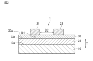
- FIG. 1 is a schematic perspective view partially showing a telescopic device according to a first embodiment of the present invention.
- FIG. 2 is a sectional view taken along line II-II in FIG.
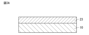
- FIG. 3A is an explanatory diagram illustrating a method for manufacturing a telescopic device.
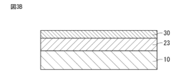
- FIG. 3B is an explanatory diagram illustrating a method for manufacturing a telescopic device.
- FIG. 3C is an explanatory diagram illustrating a method for manufacturing a telescopic device.
- FIG. 4A is a schematic cross-sectional view showing a telescopic device according to a second embodiment of the present invention.
- FIG. 4B is a schematic cross-sectional view showing a telescopic device according to a modification of the second embodiment of the present invention.
- FIG. 1 is a schematic perspective view partially showing a telescopic device according to a first embodiment of the present invention.
- FIG. 2 is a sectional view taken along line II-II in FIG.
- FIG. 5 is a schematic cross-sectional view showing a telescopic device according to a third embodiment of the present invention.
- FIG. 6 is a schematic cross-sectional view showing a telescopic device according to a fourth embodiment of the present invention.
- FIG. 7 is a schematic cross-sectional view showing a telescopic device according to a fifth embodiment of the present invention.
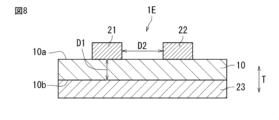
- FIG. 8 is a schematic cross-sectional view showing a telescopic device according to a sixth embodiment of the present invention.
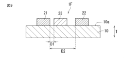
- FIG. 9 is a schematic cross-sectional view showing a telescopic device according to a seventh embodiment of the present invention.
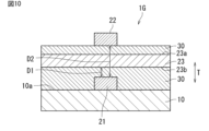
- FIG. 10 is a schematic cross-sectional view showing a telescopic device according to an eighth embodiment of the present invention.
- FIG. 10 is a schematic cross-sectional view showing a telescopic device according to an eighth embodiment of the present invention.
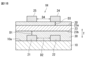
- FIG. 11A is a schematic cross-sectional view showing a telescopic device according to a ninth embodiment of the present invention.
- FIG. 11B is a schematic cross-sectional view showing a telescopic device according to a modification of the ninth embodiment of the present invention.
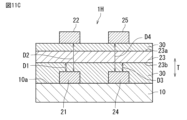
- FIG. 11C is a schematic cross-sectional view showing a telescopic device according to a modification of the ninth embodiment of the present invention.
- the present disclosure is particularly effective for circuit boards in which electrodes are formed on a base material that easily absorbs moisture, such as a stretchable base material, using a metal that easily causes migration (movement of metal ions), such as silver or copper. Migration can proceed from the positive electrode to the negative electrode.
- FIG. 1 is a schematic perspective view partially showing the telescopic device 1.
- FIG. 2 is a sectional view taken along line II-II in FIG.
- T the thickness direction of the stretchable base material
- the stretchable device 1 includes a stretchable stretchable base material 10, and a first electrode 21, a second electrode 22, and a third electrode 23 provided on the stretchable base material 10.
- the stretchable device 1 is, for example, attached to a living body and used to measure biological signals.
- on the stretchable base material does not refer to an absolute one direction such as vertically upward defined by the direction of gravity, but to the outside and inside of the stretchable base material with the surface of the stretchable base material as the boundary. It refers to the direction towards the outside. Therefore, “on the stretchable base material” is a relative direction determined by the orientation of the surface of the stretchable base material. Furthermore, “above” an element does not only mean a position directly above the element (on), but also a position above the element that is away from it, that is, a position above the element through other objects. Also includes spaced above positions.
- the stretchable base material 10 is a sheet-like or film-like base material made of a stretchable resin material.
- the resin material include thermoplastic polyurethane (TPU).
- TPU thermoplastic polyurethane
- the thickness of the stretchable base material 10 is not particularly limited, but from the viewpoint of not inhibiting the expansion and contraction of the surface of a living body when attached to a living body, it is preferably 1 mm or less, more preferably 100 ⁇ m or less, and 50 ⁇ m or less. It is more preferable that Moreover, it is preferable that the thickness of the elastic base material 10 is 1 ⁇ m or more.
- the shape of the stretchable base material 10 is not particularly limited. In this embodiment, the stretchable base material 10 is shaped to stretch in one direction when viewed from the thickness direction T.
- the first electrode 21 and the second electrode 22 are signal electrodes.
- the first electrode 21 and the second electrode 22 may be wiring.
- the shapes of the first electrode 21 and the second electrode 22 are not particularly limited.
- each of the first electrode 21 and the second electrode 22 is a wiring, and has a shape extending in one direction.
- a plurality of each of the first electrode 21 and the second electrode 22 may be provided. Further, the first electrode and the second electrode may not be provided on the same plane.
- the first electrode 21 and the second electrode 22 are formed of a conductive material. It is preferable that the first electrode 21 and the second electrode 22 have elasticity.
- the conductive material of the first electrode 21 and the second electrode 22 for example, metal foil such as silver, copper, or nickel may be used, and metal powder such as silver, copper, or nickel and epoxy resin, urethane resin, or acrylic resin may be used. and an elastomer resin such as a silicone resin may also be used.
- the electrically conductive material for the first electrode 21 and the second electrode 22 is preferably silver. Thereby, the first electrode 21 and the second electrode 22 with low resistance can be formed.
- the third electrode 23 is an electrode for suppressing migration.
- the third electrode 23 may be a wiring. A voltage for suppressing migration is applied to the third electrode 23 .
- the third electrode 23 may be used for signals in addition to migration suppression.
- the shape of the third electrode 23 is not particularly limited. In this embodiment, the third electrode 23 has a plate shape.
- the third electrode 23 may be a dummy electrode on which no signal is transmitted or received.
- the third electrode 23 is made of a conductive material. It is preferable that the third electrode 23 has elasticity. As the conductive material of the third electrode 23, a material having migration resistance (in other words, having a small ionization tendency), such as carbon or platinum, is used.
- the ionization tendency of the conductive material that is the main component of the third electrode 23 is smaller than the ionization tendency of the conductive material that is the main component of the first electrode 21 and the ionization tendency of the conductive material that is the main component of the second electrode 22.
- the "conductive material that is the main component” refers to the element that has the largest proportion (weight %) among the conductive elements contained in the electrode.
- both the first electrode 21 and the second electrode 22 can be silver electrodes
- the third electrode 23 can be a carbon electrode.
- the ionization tendency of the conductive material that is the main component of the third electrode 23, that is, carbon, is the same as the ionization tendency of the conductive material that is the main component of the first electrode 21, that is, silver, and the conductive material that is the main component of the second electrode 22. , that is, smaller than the ionization tendency of silver.
- the shortest distance D1 between the first electrode 21 and the third electrode 23 is smaller than the shortest distance D2 between the first electrode 21 and the second electrode 22.
- the shortest distance D1 refers to the minimum value of the distance between the first electrode 21 and the third electrode 23 in the opposing direction (in this embodiment, the thickness direction T of the stretchable base material 10).
- the shortest distance D2 refers to the minimum value of the distance between the first electrode 21 and the second electrode 22 in the opposing direction (in this embodiment, the left-right direction in FIG. 2).
- the shortest distance D1 and the shortest distance D2 may be measured on a cross section that is parallel to the thickness direction T of the stretchable base material 10 and intersects the first electrode 21, the second electrode 22, and the third electrode 23. In this embodiment, the shortest distance D1 and the shortest distance D2 may be measured, for example, on a cross section passing through the center of the first electrode 21 in the stretching direction and perpendicular to the stretching direction of the first electrode 21.
- the first electrode 21 and the third electrode 23 since the shortest distance D1 between the first electrode 21 and the third electrode 23 is smaller than the shortest distance D2 between the first electrode 21 and the second electrode 22, the first electrode 21 and the third electrode 23 The intensity of the electric field formed between the first electrode 21 and the second electrode 22 is greater than the intensity of the electric field formed between the first electrode 21 and the second electrode 22. Therefore, the force between the first electrode 21 and the third electrode 23 is greater than the force between the first electrode 21 and the second electrode 22. As a result, migration that may occur between the first electrode 21 and the second electrode 22 can be suppressed.
- the ionization tendency of the conductive material that is the main component of the third electrode 23 is smaller than the ionization tendency of the conductive material that is the main component of the first electrode 21 and the ionization tendency of the conductive material that is the main component of the second electrode 22. Therefore, even if the pulling force between the first electrode 21 and the third electrode 23 becomes larger than the pulling force between the first electrode 21 and the second electrode 22, the tension between the first electrode 21 and the third electrode 23 Migration that may occur between the two is suppressed. Thereby, migration that may occur in the elastic device 1 can be suppressed.
- the stretchable base material 10 has a first main surface 10a.
- the first electrode 21, the second electrode 22, and the third electrode 23 are provided on the first main surface 10a.
- the first electrode 21 and the second electrode 22 are arranged on the same plane.
- the third electrode 23 is arranged at a different position from the first electrode 21 and the second electrode 22 in the thickness direction T of the stretchable base material 10.
- the stretchable device 1 has an insulating layer 30 provided at least between the first electrode 21 and the third electrode 23 and between the second electrode 22 and the third electrode 23.
- on the first principal surface does not refer to an absolute direction such as vertically upward defined in the direction of gravity, but to the outside of the elastic substrate with the first principal surface of the elastic substrate as a boundary. It refers to the direction toward the outside of the inside. Therefore, “on the first main surface” is a relative direction determined by the orientation of the first main surface of the stretchable base material.
- the insulating layer 30 can suppress short circuits between the first electrode 21 and the third electrode 23 and between the second electrode 22 and the third electrode 23.
- the third electrode 23, the insulating layer 30, the first electrode 21, and the second electrode 22 are laminated in this order from the first main surface 10a side of the stretchable base material 10. According to this configuration, since the insulating layer 30 and the third electrode 23 are present between the first electrode 21 and the second electrode 22 and the stretchable base material 10, the first electrode 21 and the third electrode 23 are present from the stretchable base material 10 side. In addition, moisture can be prevented from entering the second electrode 22, and migration that may occur between the first electrode 21 and the second electrode 22 can be further suppressed.
- the third electrode 23 is provided on the entire first main surface 10a of the stretchable base material 10.
- the third electrode 23 is provided in a plate shape so as to cover the entire first main surface 10a of the stretchable base material 10.
- the insulating layer 30 is provided on the entire surface 23a of the third electrode 23 located on the side opposite to the stretchable base material 10 side.
- the surface 23a of the third electrode 23 corresponds to the surface located on the opposite side of the surface of the third electrode facing the stretchable base material 10.
- the insulating layer 30 is provided in a plate shape so as to cover the entire surface 23a of the third electrode 23.
- the first electrode 21 and the second electrode 22 are provided on a part of the surface 30a of the insulating layer 30 on the side opposite to the third electrode 23 side.
- the first electrode 21 extends along the stretching direction of the stretchable base material 10.
- the second electrode 22 extends along the stretching direction of the stretchable base material 10.
- the first electrode 21 and the second electrode 22 are separated by the shortest distance D2.
- the insulating layer 30 electrically insulates the first electrode 21, the second electrode 22, and the third electrode 23. It is preferable that the insulating layer 30 has elasticity.
- the insulating layer 30 may or may not be water absorbent.
- the shape of the insulating layer 30 is not particularly limited as long as it can electrically insulate the first electrode 21, the second electrode 22, and the third electrode 23.
- the insulating material of the insulating layer 30 is not particularly limited as long as it can electrically insulate the first electrode 21, the second electrode 22, and the third electrode 23.
- the insulating material of the insulating layer 30 is, for example, polyester resin.
- the polarity of the potential of the first electrode 21 is different from the polarity of the potential of the second electrode 22, and the polarity of the potential of the third electrode 23 is different from the polarity of the potential of the first electrode 21. According to this configuration, signals with different polarities can be extracted from the first electrode 21 and the second electrode 22.
- the first electrodes 21 and second electrodes 22 are arranged alternately along the direction perpendicular to the extending direction of the first electrodes 21, and
- the polarity of the potential of the first electrode 21 may be made different from the polarity of the potential of the second electrode 22, and the polarity of the potential of the third electrode 23 may be made different from the polarity of the potential of the first electrode 21.
- the polarity of the potential of the first electrode 21 is negative.
- the polarity of the potential of the second electrode 22 is positive
- the polarity of the potential of the third electrode 23 is positive.
- the first electrode 21 and the third electrode 23 since the shortest distance D1 between the first electrode 21 and the third electrode 23 is smaller than the shortest distance D2 between the first electrode 21 and the second electrode 22, the first electrode 21 and the third electrode 23 The intensity of the electric field formed between the first electrode 21 and the second electrode 22 is greater than the intensity of the electric field formed between the first electrode 21 and the second electrode 22. Therefore, according to the above configuration, positive ions are suppressed from moving from the second electrode 22 to the first electrode 21 via the insulating layer 30, and are generated between the first electrode 21 and the second electrode 22.
- the polarity of the potential of the third electrode is positive, movement of cations from the second electrode 22 to the third electrode 23 via the insulating layer 30 is suppressed.
- the ionization tendency of the conductive material that is the main component of the third electrode 23 is different from the ionization tendency of the conductive material that is the main component of the first electrode 21 and that of the conductive material that is the main component of the second electrode 22. Since the ionization tendency is smaller than the ionization tendency, the movement of cations from the third electrode 23 to the first electrode 21 via the insulating layer 30 is suppressed. As described above, according to the above configuration, migration that may occur in the telescopic device 1 can be further suppressed.
- the third electrode 23 when the third electrode 23 is not provided, when the polarity of the potential of the first electrode 21 is negative and the polarity of the potential of the second electrode 22 is positive, the cations are can be easily moved from the second electrode 22 to the first electrode 21 via the . As a result, migration may occur between the first electrode 21 and the second electrode 22. Furthermore, even when the third electrode 23 is provided, the ionization tendency of the conductive material that is the main component of the third electrode 23 is different from the ionization tendency of the conductive material that is the main component of the first electrode 21 and that of the second electrode 22.
- the ionization tendency is the same as or greater than the ionization tendency of the conductive material that is the main component, cations can easily move from the third electrode 23 to the first electrode 21 via the insulating layer 30. As a result, migration may occur between the first electrode 21 and the third electrode 23.
- the third electrode 23 overlaps the entire first electrode 21 when viewed from the thickness direction T of the stretchable base material 10. More preferably, the third electrode 23 overlaps the entire first electrode 21 when viewed from the thickness direction T of the stretchable base material 10, and the planar area of the third electrode 23 is larger than the planar area of the first electrode 21. According to this configuration, since the third electrode can be easily aligned, the third electrode 23 can be easily formed. Further, since the first electrode 21 is arranged directly above the third electrode 23, the shortest distance D1 between the first electrode 21 and the third electrode 23 can be made smaller, and the distance between the first electrode 21 and the second electrode 22 can be further suppressed.
- the third electrode 23 overlaps the entire first electrode 21 and the entire second electrode 22 when viewed from the thickness direction T of the stretchable base material 10. More preferably, the third electrode 23 is a third electrode that overlaps the entire first electrode 21 and the entire second electrode 22 and overlaps the entire first electrode 21 when viewed from the thickness direction T of the stretchable base material 10. 23 and a third electrode that overlaps the entire second electrode 22 are integral, and the planar area of the third electrode 23 is the combined planar area of the first electrode 21 and the second electrode 22. larger than According to this configuration, for example, the third electrode 23 can be formed in a plate shape so as to cover the entire first main surface 10a of the stretchable base material 10, and patterning of the third electrode 23 is not required. 23 can be easily formed. Further, since the first electrode 21 is arranged directly above the third electrode 23, the shortest distance D1 between the first electrode 21 and the third electrode 23 can be made smaller, and the distance between the first electrode 21 and the second electrode 22 can be further suppressed.
- a protective layer (not shown) is provided on the insulating layer 30 so as to cover the first electrode 21 and the second electrode 22.
- the protective layer is preferably made of a stretchable resin material, such as an ionomer resin, a polyester resin, a styrene resin, an olefin resin, an epoxy resin, a urethane resin, an acrylic resin, or a silicone resin. According to this configuration, the first electrode 21 and the second electrode 22 can be protected from the external environment. Further, the insulating layer 30 may be arranged to cover the first electrode 21 and the second electrode 22.
- FIGS. 3A, 3B, and 3C are explanatory diagrams illustrating a method for manufacturing the telescopic device 1.
- the process conditions, materials used, etc. of the telescopic device 1 are specifically shown, but the following is just an example of the manufacturing method of the telescopic device 1, and the manufacturing method of the telescopic device 1 is as follows. Not limited by process conditions and materials used.
- the third electrode 23 is formed on the stretchable base material 10 by, for example, screen printing.
- the stretchable base material 10 is, for example, thermoplastic polyurethane (TPU). Process conditions and materials used are as follows, for example.
- ⁇ Third electrode material DuPont carbon electrode 7105 ⁇ Stretchable base material: DUS605_6UVPT (50 ⁇ m thick) manufactured by Seedam ⁇ Printing plate: SP plate (mesh: #500, linear 18 ⁇ m, emulsion thickness 11 ⁇ m, inner size 280mm square), pattern area: 150 x 150mm ⁇ Printing conditions: Squeegee: Micro squeegee (rubber hardness: 70°), Squeegee pressure: 200N/160mm width, Squeegee speed: 150mm/s, Squeegee attack angle: 60°, Distance: 1.5mm ⁇ Drying conditions: Circulating oven 100°C x 30 minutes
- an insulating layer 30 is formed on the third electrode 23 by, for example, screen printing.
- Process conditions and materials used are as follows, for example.
- ⁇ Insulating layer material Henkel ELECTRODAG 452SS ⁇ Printing plate: SP plate (mesh: #352, linear 23 ⁇ m, emulsion thickness 17 ⁇ m, inner size 280mm square), pattern area: 150 x 150mm ⁇ Printing conditions: Squeegee: Micro squeegee (rubber hardness: 70°), Squeegee pressure: 200N/160mm width, Squeegee speed: 150mm/s, Squeegee attack angle: 70°, Distance: 1.5mm ⁇ Curing conditions: UV light irradiation; 500 mJ/cm 2 at i-ray (365 nm)
- the first electrode 21 and the second electrode 22 are formed on the insulating layer 30 by, for example, screen printing.
- Process conditions and materials used are as follows, for example.
- ⁇ Electrode material DuPont silver electrode 5064 ⁇ Printing plate: SP plate (mesh: #500, linear 18 ⁇ m, emulsion thickness 11 ⁇ m, inner size 280mm square), pattern area: 150 x 150mm ⁇ Printing conditions: Squeegee: Micro squeegee (rubber hardness: 70°), Squeegee pressure: 100N/160mm width, Squeegee speed: 150mm/s, Squeegee attack angle: 50°, Distance: 1.5mm ⁇ Drying conditions: Circulating oven 100°C x 30 minutes
- FIG. 4A corresponds to the II-II cross section in FIG.
- the elastic device 1A is different from the elastic device 1 according to the first embodiment in the shape of the insulating layer.
- the insulating layer 30A of the stretchable device 1A includes a first portion 31 provided between the first electrode 21 and the third electrode 23 and a second portion provided between the second electrode 22 and the third electrode 23. 32.
- the first portion 31 and the second portion 32 are separated from each other.
- the insulating layer 30A is divided into a first portion 31 and a second portion 32.
- the insulating layer 30A may be divided into three or more parts.
- the first portion 31 is provided between the first electrode 21 and the third electrode 23 and electrically insulates the first electrode 21 and the third electrode 23.
- the first portion 31 extends along the direction in which the first electrode 21 extends.
- the second portion 32 is provided between the second electrode 22 and the third electrode 23 and electrically insulates the second electrode 22 and the third electrode 23.
- the second portion 32 extends along the extending direction of the second electrode 22.
- the first portion 31 and the second portion 32 are separated from each other by a predetermined distance in the direction in which the first electrode 21 and the second electrode 22 face each other (the left-right direction in FIG. 4A).
- the path through which ions move within the insulating layer 30A can be cut off between the first electrode 21 and the second electrode 22. Therefore, migration that may occur between the first electrode 21 and the second electrode 22 can be further suppressed.
- the insulating layers 30A are arranged at intervals on the stretchable base material 10. This reduces the planar area of the insulating layer 30A compared to a case where the insulating layer is continuous, so that the influence that the insulating layer 30A may have on the stretchability of the stretchable device 1A can be further reduced. Therefore, according to the above structure, it is possible to obtain a stretchable device with better stretchability while suppressing migration with the insulating layer.
- the stretchable device can be attached to a living body, for example.
- the elastic device When used on such a living body, the elastic device may be required to have breathability in order to reduce discomfort such as stuffiness when the elastic device is worn. This may be achieved, for example, by using a breathable material for the stretchable base material 10.
- a material with low air permeability as the insulating layer. Therefore, when the insulating layer is disposed over the entire stretchable device 1A when viewed from the thickness direction T of the stretchable base material 10, the air permeability may be reduced.
- the stretchable device 1A includes a region on the stretchable base material 10A between the first portion 31 and the second portion 32 where the insulating layer 30A is not provided. Thereby, reduction in air permeability of the stretchable device due to the insulating layer can be suppressed. That is, a stretchable device with good air permeability can be realized while suppressing migration by the insulating layer.
- one continuous insulating layer 30 is formed over the entire stretchable device when viewed from the thickness direction T of the stretchable base material 10, whereas in the second embodiment, the insulation layer 30 has a small planar area.
- Multiple layers are provided. That is, in the stretchable device 1A of the second embodiment, the insulating layer 30A is divided into the first portion 31 and the second portion 32, so that the area of the continuously provided insulating layer can be reduced. As a result, the thickness of the insulating layer can be controlled more precisely than when one continuous insulating layer is provided over a wide area. Specifically, non-uniformity in the thickness of the insulating layer due to uneven printing or the like can be reduced, and a stretchable device 1A including the insulating layer 30A having a more uniform thickness can be provided.
- the thickness of the insulating layer 30A may correspond to the shortest distance D1 between the first electrode 21 and the third electrode 23. Since the insulating layer 30A has a uniform thickness as described above, the shortest distance D1 becomes more uniform between the first electrode 21 and the third electrode 23, so that migration can be suppressed more suitably.
- the protective layer 40 may exist in the space between the first part 31 and the second part 32 (see FIG. (See 4B). Thereby, migration that may occur between the first electrode 21 and the second electrode 22 can be further suppressed. Further, since the protective layer 40 is present so as to bite into the space between the first portion 31 and the second portion 32, the protective layer can be suitably held by an anchor effect. Thereby, peeling of the protective layer 40 from the stretchable device 1A can be suitably suppressed.
- FIG. 5 corresponds to the II-II cross section in FIG.
- the elastic device 1B is different from the elastic device 1 according to the first embodiment in the shape of the third electrode.
- the third electrode 23B of the stretchable device 1B has a shape corresponding to the shapes of the first electrode 21 and the second electrode 22.
- the third electrode 23B includes a first portion 231 shaped to correspond to the shape of the first electrode 21, a second portion 232 shaped to correspond to the shape of the second electrode 22, has. That is, the first portion 231 extends linearly along the extending direction of the first electrode 21.
- the second portion 232 extends linearly along the direction in which the second electrode 22 extends.
- the third electrode 23B is divided into a first portion 231 and a second portion 232.
- the first portion 231 overlaps with the first electrode 21 when viewed from the thickness direction T of the stretchable base material 10.
- the second portion 232 overlaps with the second electrode 22 when viewed from the thickness direction T of the stretchable base material 10.
- the third electrode 23B since the third electrode 23B is divided, the electric field formed between the first electrode 21 and the third electrode 23B is reduced compared to a case where the third electrode 23B is not divided. You can concentrate. Therefore, the force in which the first electrode 21 and the third electrode 23B are pulled together becomes even larger than the force in which the first electrode 21 and the second electrode 22 are pulled together. As a result, migration that may occur between the first electrode 21 and the second electrode 22 can be further suppressed. Moreover, since the planar area of the third electrode 23B can be made smaller compared to the case where the third electrode 23B is not divided, the stretchability of the stretchable device 1B can be improved.
- the stretchable device can use transparent or translucent materials for materials other than the electrodes (ie, the stretchable base material 10, the insulating layer 30, and/or the protective layer, etc.).
- the third electrode 23B does not cover the first main surface 10a of the transparent or translucent stretchable base material 10 over the front surface, and when viewed from the thickness direction T of the stretchable base material 10, the first electrode 21 or It is arranged in a region overlapping with the second electrode 22. That is, when viewed from the thickness direction T of the stretchable base material 10, the stretchable device has electrodes arranged only in a partial area of the first main surface 10a of the transparent or semitransparent stretchable base material 10.
- the stretchable device when viewed from the thickness direction T of the stretchable base material 10, can include a transparent or semitransparent region in a region that does not include an electrode. Thereby, it becomes possible to visually recognize the mounting position of the telescopic device through the transparent or semi-transparent region.
- the second portion 232 of the third electrode 23B is preferably provided in order to alleviate unevenness on the upper surface of the insulating layer 30 that may be caused by the third electrode 23B, but it may not be provided. In this case, since the electric field formed between the first electrode 21 and the third electrode 23B can be further concentrated, migration that may occur between the first electrode 21 and the second electrode 22 can be further suppressed. .
- FIG. 6 corresponds to the II-II cross section in FIG.
- the stretchable device 1C is different from the stretchable device 1 according to the first embodiment in the shape of the third electrode.
- the third electrode 23C of the stretchable device 1C does not overlap the first electrode 21 and the second electrode 22 when viewed from the thickness direction T of the stretchable base material 10. Specifically, the third electrode 23C is provided on a part of the first main surface 10a of the stretchable base material 10. The third electrode 23C extends linearly along the extending direction of the first electrode 21. The third electrode 23C is arranged between the first electrode 21 and the second electrode 22 when viewed from the thickness direction T of the stretchable base material 10.
- the first electrode 21, the third electrode 23, and the second electrode 22 are arranged along the direction perpendicular to the thickness direction T of the stretchable base material. Since they can be arranged alternately in a staggered manner, the elasticity of the elastic device 1C can be made uniform. In particular, as described above, when the insulating layer 30 is arranged to cover the first electrode 21 and the second electrode 22, the elasticity of the elastic device 1C can be made more uniform.
- the thickness of the insulating layer 30 can be reduced.
- the third electrodes 23C are arranged alternately so as not to overlap the first electrodes 21 and the second electrodes 22.
- the shortest distance D1 between the first electrode 21 and the third electrode 23C is suitably secured, and the distance between the insulating layer 30
- the thickness can be reduced.
- the insulating layer 30 covering the third electrode 23C is different from the case where the first electrode 21, the second electrode 22, and the third electrode 23C overlap in the thickness direction T (for example, the configuration shown in FIG. 5). and may have a smaller thickness. Thereby, the height of the telescopic device can be further reduced.
- the thickness of the insulating layer 30 in the stretched state may be smaller than the thickness of the insulating layer 30 in the non-stretched state in the cross-sectional view shown in FIG.
- the third electrode 23C does not overlap the first electrode 21 and the second electrode 22 when viewed from the thickness direction T of the stretchable base material 10
- the thickness of the insulating layer 30 is relatively reduced by stretching.
- contact between the electrodes can be suitably prevented.
- the cross-sectional area A3 of the third electrode 23C is equal to the cross-sectional area A1 of the first electrode 21. 105% or less. According to this configuration, the elasticity of the elastic device 1C can be improved. More preferably, the cross-sectional area A3 of the third electrode 23C is 100% or less of the cross-sectional area A1 of the first electrode 21.
- the cross-sectional area A3 of the third electrode 23C is the same as that of the second electrode 22. It is 105% or less of the cross-sectional area A2. More preferably, the cross-sectional area A3 of the third electrode 23C is 100% or less of the cross-sectional area A2 of the second electrode 22. The closer the cross-sectional areas of the first electrode 21, the second electrode 22, and the third electrode 23 are to the same, the more uniform the elasticity of the elastic device 1C can be.
- the cross-sectional area A3 of the third electrode 23C is equal to the cross-sectional area A1 of the first electrode 21.
- 10% or more of The cross-sectional area A3 of the third electrode 23C is more preferably 50% or more, and even more preferably 90% or more, of the cross-sectional area A1 of the first electrode 21. According to this configuration, the cross-sectional areas of the first electrode 21, the second electrode 22, and the third electrode 23 become nearly the same, and the stretchability of the stretchable device 1C can be made even more uniform.
- the cross-sectional area A3 of the third electrode 23C is the same as that of the second electrode 22. It is 10% or more of the cross-sectional area A2.
- the cross-sectional area A3 of the third electrode 23C is more preferably 50% or more, and even more preferably 90% or more, of the cross-sectional area A2 of the second electrode 22. If the cross-sectional area A3 of the third electrode 23C is too small, the effect of suppressing migration may be reduced. By setting the lower limit of the cross-sectional area A3 of the third electrode 23C as described above, migration that may occur between the first electrode 21 and the second electrode 22 can be effectively suppressed.
- FIG. 7 corresponds to the II-II cross section in FIG.
- the stretchable device 1D is different from the stretchable device 1 according to the first embodiment in the positional relationships among the first electrode, the second electrode, the insulating layer, and the third electrode.
- the first electrode 21 and the second electrode 22 are provided on the first main surface 10a of the stretchable base material 10.
- the insulating layer 30 is provided on the first main surface 10a of the stretchable base material 10 so as to cover the first electrode 21 and the second electrode 22.
- the third electrode 23 is provided on the surface 30a of the insulating layer 30 on the opposite side to the first main surface 10a side of the stretchable base material 10. Note that in this embodiment, the position where the third electrode 23 is provided is not particularly limited; for example, the third electrode 23 may be provided below the first electrode 21 and the second electrode 22. .
- the first electrode 21 and the second electrode 22 are covered with the insulating layer 30, the first electrode 21 is protected from moisture that may enter from the upper side of the elastic base material 10 (the upper side in FIG. 7). And the second electrode 22 can be protected. Further, when the third electrode 23 is provided on the surface 30a of the insulating layer 30, the patterns of the first electrode 21 and the second electrode 22 can be hidden by the third electrode 23. In such a configuration, the third electrode 23 can also serve as a protective layer for the first electrode 21 and the second electrode 22. For example, the third electrode 23 can serve as a protective layer that suppresses moisture from entering the stretchable device 1D from the third electrode 23 side (upper side in FIG. 7).
- FIG. 8 corresponds to the II-II cross section in FIG.
- the stretchable device 1E is different from the stretchable device 1 according to the first embodiment in that an insulating layer is not provided and the position where the third electrode is provided.
- the stretchable base material 10 has a first main surface 10a and a second main surface 10b facing each other, a first electrode 21 and a second electrode 22 are provided on the first main surface 10a, and a third electrode 23 is provided on the first main surface 10a. , are provided on the second main surface 10b.
- the insulating layer 30 is not provided because electrical insulation between the first electrode 21, the second electrode 22, and the third electrode 23 can be ensured by the elastic base material 10.
- the manufacturing process can be simplified and manufacturing costs can be reduced.
- the thickness of the stretchable device 1E is reduced as a whole, and the height of the stretchable device can be made lower.
- the shortest distance D1 between the first electrode 21 and the third electrode 23 corresponds to the thickness of the elastic base material 10. Therefore, by providing the first electrode 21 and the second electrode 22 on one main surface 10a of the elastic base material 10 and providing the third electrode 23 on the other main surface 10b, it is possible to Therefore, the first electrode 21 and the third electrode 23 can be evenly spaced apart.
- the third electrode 23 may be a gel electrode.
- the stretchable device can be easily attached to a living body or the like. That is, by using the third electrode 23 as a gel electrode, the third electrode 23 can function as an adhesive layer for attaching the elastic device to a living body or the like.
- the gel electrode is composed of a conductive gel material containing, for example, water, alcohol, a humectant, an electrolyte, and the like. Examples of such gel materials include hydrogels having adhesive properties.
- FIG. 9 corresponds to the II-II cross section in FIG.
- the stretchable device 1F is different from the stretchable device 1 according to the first embodiment in that an insulating layer is not provided and the position where the third electrode is provided.
- the first electrode 21, the second electrode 22, and the third electrode 23 are provided on the same plane.
- the third electrode 23 is provided on the first main surface 10a of the stretchable base material 10, similarly to the first electrode 21 and the second electrode 22.
- the third electrode 23 extends linearly along the extending direction of the first electrode 21 .
- the third electrode 23 is arranged between the first electrode 21 and the second electrode 22.
- the third electrode 23 is spaced apart from each of the first electrode 21 and the second electrode 22.
- the insulating layer 30 is not provided.
- the manufacturing process can be simplified and manufacturing costs can be reduced. Furthermore, since it is not necessary to provide the insulating layer 30, the elastic device 1F can be made thinner.
- the third electrode 23 can prevent the bleeding of the second electrode 22 from reaching the first electrode 21 during printing. can be suitably suppressed.
- the third electrode 23 can also contribute to suppressing printing blur of the second electrode 22. Therefore, according to the above configuration, the distance D2 between the first electrode 21 and the second electrode 22 can be made smaller, and the expansion/contraction device can be made more compact.
- the first electrode 21, the second electrode 23, and the third electrode 23 can be arranged by controlling the printing pattern on the first main surface 10a.
- the distance D1 between the first electrode 21 and the third electrode 23, and the distance D2 between the first electrode 21 and the second electrode 22 can be more easily controlled.
- FIG. 10 corresponds to the II-II cross section in FIG.
- the stretchable device 1G is different from the stretchable device 1 according to the first embodiment in that a first electrode 21 and a second electrode 22 are stacked with a third electrode 23 and an insulating layer 30 interposed therebetween. .
- the first electrode 21 and the second electrode 22 are stacked with the third electrode 23 in between.
- the first electrode 21 is provided on the first main surface 10a of the stretchable base material 10.
- the insulating layer 30 is provided on the first main surface 10a of the stretchable base material 10 so as to cover the first electrode 21.
- the third electrode 23 is arranged so as to face the first electrode 21 with the insulating layer 30 in between, on a surface 23b (hereinafter also referred to as second surface 23b) of the stretchable base material 10 that faces the first main surface 10a.
- An insulating layer 30 is further provided on a surface 23a (hereinafter also referred to as first surface 23a) of the third electrode 23 located on the opposite side to the second surface 23b.
- the second electrode 22 is arranged on the insulating layer 30 located on the first surface 23a.
- the insulating layer is provided between the first electrode 21 and the third electrode 23 and between the second electrode 22 and the third electrode 23. That is, the third electrode 23 includes the insulating layer 30 on both surfaces of the second surface 23b facing the first main surface of the stretchable base material 10 and the first surface 23a opposite to the second surface 23b. In other words, the third electrode 23 is located between the two insulating layers 30.
- the stretchable device 1G has a structure in which the first electrode 21, the insulating layer 30, the third electrode 23, the insulating layer 30, and the second electrode 22 are laminated in this order on the stretchable base material 10.
- first electrode 21 and the second electrode 22 may be reversed. That is, the second electrode 22 may be located between the stretchable base material 10 and the third electrode 23, and the first electrode 22 may be located on the first surface 23a side of the third electrode.
- the above configuration since the first electrode 21 and the second electrode 22 are physically separated by the third electrode 23, migration between the first electrode 21 and the second electrode 22 can be more preferably prevented. . Furthermore, as described above, the ionization tendency of the conductive material that is the main component of the third electrode 23 is smaller than the ionization tendency of the conductive material that is the main component of the first electrode 21 and the second electrode 22. Ion movement between 21 and third electrode 23 is suppressed. Therefore, the above configuration can provide a telescopic device 1G that can suppress the occurrence of migration.
- a telescopic device 1H according to the ninth embodiment will be described below with reference to FIGS. 11A to 11C.
- 11A to 11C correspond to the II-II cross section in FIG. 1, respectively.
- the elastic device 1H is different from the elastic device 1 according to the first embodiment in that in addition to the first electrode 21 and the second electrode 22, a fourth electrode 24 and a fifth electrode 25 are further arranged. do.
- the first electrode 21 and the second electrode 24 are located on the same plane. That is, the first electrode 21 and the second electrode 22 are provided on the first main surface 10a of the stretchable base material 10.
- the insulating layer 30 is provided on the first main surface 10a of the stretchable base material 10 so as to cover the first electrode 21 and the second electrode 22.
- the third electrode 23 is provided on the second surface 23b side so as to face the first electrode 21 and the second electrode 22 with the insulating layer 30 in between.
- a fourth electrode 24 and a fifth electrode 25 are arranged on the insulating layer located on the first surface 23a side of the third electrode 23.
- the fourth electrode 24 and the fifth electrode 25 may be located on the same plane.
- the fourth electrode 24 and the fifth electrode 25 are arranged to face the first surface 23a of the third electrode 23 with the insulating layer 30 in between.
- the first electrode 21 and the second electrode 22, and the fourth electrode 24 and the fifth electrode 25 are stacked with the insulating layer 30 and the third electrode 23 in between.
- the ionization tendency of the conductive material that is the main component of the third electrode 23 is smaller than the ionization tendency of the conductive material that is the main component of the fourth electrode 24 and the ionization tendency of the conductive material that is the main component of the fifth electrode 25.
- both the fourth electrode 24 and the fifth electrode 25 can be silver electrodes
- the third electrode 23 can be a carbon electrode.
- the ionization tendency of the conductive material that is the main component of the third electrode 23, that is, carbon is the same as the ionization tendency of the conductive material that is the main component of the fourth electrode 24, that is, silver, and the conductive material that is the main component of the fifth electrode 25. , that is, smaller than the ionization tendency of silver.
- the shortest distance D3 between the fourth electrode 24 and the third electrode 23 is smaller than the shortest distance D4 between the fourth electrode 24 and the fifth electrode 25.
- the shortest distance D3 refers to the minimum value of the distance between the fourth electrode 24 and the third electrode 23 in the opposing direction (in this embodiment, the thickness direction T of the stretchable base material 10).
- the shortest distance D4 refers to the minimum value of the distance between the fourth electrode 24 and the fifth electrode 25 in the opposing direction (in this embodiment, the left-right direction in FIG. 2).
- the shortest distance D3 and the shortest distance D4 may be measured on a cross section that is parallel to the thickness direction T of the stretchable base material 10 and intersects the fourth electrode 24, the fifth electrode 25, and the third electrode 23. In this embodiment, the shortest distance D3 and the shortest distance D4 may be measured, for example, on a cross section passing through the center of the fourth electrode 24 in the stretching direction and perpendicular to the stretching direction of the fourth electrode 24.
- the shortest distance D3 between the fourth electrode 24 and the third electrode 23 is smaller than the shortest distance D4 between the fourth electrode 24 and the fifth electrode 25.
- the intensity of the electric field formed between the fourth electrode 24 and the fifth electrode 25 is greater than the intensity of the electric field formed between the fourth electrode 24 and the fifth electrode 25. Therefore, ion movement between the fourth electrode 24 and the fifth electrode 25 is suppressed, and as a result, migration between the fourth electrode 24 and the fifth electrode 25 can be suppressed.
- the ionization tendency of the conductive material that is the main component of the third electrode 23 is smaller than the ionization tendency of the conductive material that is the main component of the fourth electrode 24 and the ionization tendency of the conductive material that is the main component of the fifth electrode 25. Therefore, migration that may occur between the fourth electrode 24 and the third electrode 23 is also suppressed. Thereby, migration that may occur in the elastic device 1 can be suppressed.
- a plurality of electrodes can be stacked and arranged while preventing migration between the electrodes by the third electrode 23.
- the area of the expansion/contraction device can be reduced compared to a structure in which a plurality of electrodes are arranged on the same plane. Therefore, a more compact telescopic device can be obtained.
- the polarity of the potential of the first to fifth electrodes is such that while the first electrode 21 and the fourth electrode 24 have the same potential polarity, the polarity of the potential of the second electrode 22, the third electrode 23, and the fifth electrode is different from the potential polarity. Electrodes 25 may have the same potential polarity. For example, the polarity of the potentials of the first electrode 21 and the fourth electrode 24 may be negative, and the polarity of the potentials of the second electrode 22, the third electrode 23, and the fifth electrode 25 may be positive. According to the above configuration, the presence of the third electrode 23 suppresses the movement of metal ions from the second electrode 22 and the fifth electrode 25 having positive polarity. Therefore, even in a stacked stretchable device including a plurality of electrodes, the occurrence of migration can be suitably suppressed.
- the arrangement of the first electrode 21, second electrode 22, fourth electrode 24, and fifth electrode 25 shown in FIG. 8 is mutually interchangeable. Simply put, the first electrode 21, the second electrode 22, the fourth electrode 24, and the fifth electrode 25 are compatible in terms of arrangement.
- the arrangement of the fourth electrode 24 and the arrangement of the fifth electrode 25 may be reversed compared to the stretchable device 1H of FIG. 11A. That is, electrodes having the same potential polarity may be arranged to face each other with the third electrode 23 in between, or alternatively, electrodes having different potential polarities may be arranged to face each other with the third electrode 23 in between. They may be arranged to face each other with 23 in between.
- the arrangement of the second electrode 22 and the arrangement of the fourth electrode 24 may be reversed compared to the stretchable device 1H of FIG. 11A.
- the first electrode 21 and the fourth electrode 24, which have the same potential polarity, are located on the same plane, and the potential polarity is the same on the opposite side of the third electrode 23.
- the second electrode 22 and the fifth electrode 25 may be located on the same plane.
- a plurality of electrodes with the same potential polarity are arranged on the same plane, and electrodes with different potential polarities are arranged so as to face each other with the third electrode 23 in between. It's fine.
- the ion movement path between the first electrode 21 and the second electrode 22 and the fourth electrode 24 and the fifth electrode 25 is physically blocked by the third electrode 23.
- the presence of the third electrode 23 prevents ion movement across the third electrode 23, so that the occurrence of migration can be suppressed more suitably.
- each embodiment is an example, and the present invention is not limited to each embodiment.
- each drawing is an illustration of the constituent elements, and does not limit the shape.
- partial substitution or combination of the configurations shown in different embodiments is possible.
- a stretchable stretchable base material A first electrode, a second electrode, and a third electrode provided on the stretchable base material,
- the ionization tendency of the conductive material that is the main component of the third electrode is smaller than the ionization tendency of the conductive material that is the main component of the first electrode and the ionization tendency of the conductive material that is the main component of the second electrode,
- the shortest distance between the first electrode and the third electrode is smaller than the shortest distance between the first electrode and the second electrode.
- the elastic device wherein the first electrode has a negative potential polarity.
- the stretchable base material has a first main surface, The first electrode, the second electrode, and the third electrode are provided on the first main surface, the first electrode and the second electrode are arranged on the same plane, The third electrode is arranged at a different position from the first electrode and the second electrode in the thickness direction of the stretchable base material, Any one of ⁇ 1> to ⁇ 3>, further comprising an insulating layer provided at least between the first electrode and the third electrode and between the second electrode and the third electrode.
- the elastic device according to ⁇ 4> wherein the third electrode, the insulating layer, the first electrode, and the second electrode are laminated in this order from the first main surface side.
- the insulating layer includes a first portion provided between the first electrode and the third electrode, and a second portion provided between the second electrode and the third electrode.
- the first electrode, the second electrode, the insulating layer, and the third electrode are stacked in any one of ⁇ 4> to ⁇ 6> in this order from the first main surface side. Telescoping device as described.
- the stretchable base material has a first main surface and a second main surface facing each other, The first electrode and the second electrode are provided on the first main surface, The elastic device according to any one of ⁇ 1> to ⁇ 3>, wherein the third electrode is provided on the second main surface.
- the third electrode overlaps the entire first electrode and the entire second electrode when viewed from the thickness direction of the elastic base material.
- ⁇ 11> The stretchable device according to any one of ⁇ 1> to ⁇ 8>, wherein the third electrode does not overlap the first electrode and the second electrode when viewed from the thickness direction of the stretchable base material.
- ⁇ 12> In a cross section that is parallel to the thickness direction of the stretchable base material and intersects the first electrode and the third electrode, the cross-sectional area of the third electrode is 105% or less of the cross-sectional area of the first electrode.
- the telescopic device according to any one of ⁇ 1> to ⁇ 11>.
- the first electrode and the second electrode are stacked with the third electrode in between, As described in any one of ⁇ 1> to ⁇ 3>, further comprising an insulating layer provided between the first electrode and the third electrode and between the second electrode and the third electrode.
- telescopic device As described in any one of ⁇ 1> to ⁇ 3>, further comprising an insulating layer provided between the first electrode and the third electrode and between the second electrode and the third electrode.
- ⁇ 14> Further comprising a fourth electrode and a fifth electrode provided on the stretchable base material,
- the ionization tendency of the conductive material that is the main component of the third electrode is smaller than the ionization tendency of the conductive material that is the main component of the fourth electrode and the ionization tendency of the conductive material that is the main component of the fifth electrode
- the telescopic device according to any one of ⁇ 1> to ⁇ 3>, wherein the shortest distance between the fourth electrode and the third electrode is smaller than the shortest distance between the fourth electrode and the fifth electrode.
- the polarity of the potential of the first electrode is the same as the polarity of the potential of the fourth electrode
- the first electrode and the second electrode are arranged on the same plane
- the fourth electrode and the fifth electrode are arranged on the same plane
- the stretchable base material, the first electrode and the second electrode, the third electrode, the fourth electrode and the fifth electrode are laminated in this order, ⁇ 14> or ⁇ 15>, comprising an insulating layer provided between the first electrode, the second electrode, and the third electrode, and between the fourth electrode, the fifth electrode, and the third electrode.
- the first electrode and the fourth electrode are arranged on the same plane
- the second electrode and the fifth electrode are arranged on the same plane
- the stretchable base material, the first electrode and the fourth electrode, the third electrode, the second electrode and the fifth electrode are laminated in this order, ⁇ 14> or ⁇ 15>, comprising an insulating layer provided between the first electrode, the fourth electrode, and the third electrode, and between the second electrode, the fifth electrode, and the third electrode.
- Stretchable device 10 Stretchable base material 10a: First main surface 10b: Second main surface 21: First electrode 22: Second electrode 23, 23B, 23C: First 3 electrodes 231: First portion 232: Second portion 30, 30A: Insulating layer 40: Protective layer A1, A2, A3: Cross-sectional area D1, D2: Shortest distance T: Thickness direction of elastic base material
Abstract
The present invention provides an expansion/contraction device which is provided with: an expansion/contraction base material that is stretchable; and a first electrode, a second electrode and a third electrode, which are provided on the expansion/contraction base material. The ionization tendency of a conductive material that is a main component of the third electrode is lower than the ionization tendency of a conductive material that is a main component of the first electrode and the ionization tendency of a conductive material that is a main component of the second electrode; and the shortest distance between the first electrode and the third electrode is shorter than the shortest distance between the first electrode and the second electrode.
Description
本発明は、伸縮デバイスに関する。
The present invention relates to a telescopic device.
従来、伸縮デバイスとしては、特許第3518023号公報(特許文献1)に記載されたものがある。この伸縮デバイスは、絶縁性合成樹脂基材上に設けられた銀レジン系パターンと、銀レジン系パターンの一部を露出させるように、銀レジン系パターン上に設けられた絶縁性樹脂レジンと、銀レジン系パターンの露出部分に設けられたふっ素系樹脂薄膜と、を備える。
Conventionally, as a telescopic device, there is one described in Japanese Patent No. 3518023 (Patent Document 1). This stretchable device includes a silver resin pattern provided on an insulating synthetic resin base material, an insulating resin resin provided on the silver resin pattern so as to expose a part of the silver resin pattern, A fluororesin thin film provided on the exposed portion of the silver resin pattern.
しかし、前記従来のような伸縮デバイスでは、銀レジン系パターンにマイグレーションが生じるおそれがあった。特に、高負荷電圧が銀レジン系パターンに印加される場合、マイグレーションが顕著に生じるおそれがあった。
However, in the conventional stretchable device described above, there was a risk that migration would occur in the silver resin pattern. In particular, when a high load voltage is applied to a silver resin pattern, there is a risk that migration will occur significantly.
そこで、本開示は、マイグレーションを抑制できる伸縮デバイスを提供することにある。
Therefore, an object of the present disclosure is to provide a stretchable device that can suppress migration.
上記目的を達成するために本発明の一態様に係る伸縮デバイスは、
伸縮可能な伸縮基材と、
前記伸縮基材上に設けられた第1電極、第2電極および第3電極と、を備え、
前記第3電極の主成分である導電材料のイオン化傾向は、前記第1電極の主成分である導電材料のイオン化傾向および前記第2電極の主成分である導電材料のイオン化傾向よりも小さく、
前記第1電極と前記第3電極との最短距離は、前記第1電極と前記第2電極との最短距離よりも小さい。 In order to achieve the above object, a telescopic device according to one aspect of the present invention includes:
A stretchable stretchable base material;
A first electrode, a second electrode, and a third electrode provided on the stretchable base material,
The ionization tendency of the conductive material that is the main component of the third electrode is smaller than the ionization tendency of the conductive material that is the main component of the first electrode and the ionization tendency of the conductive material that is the main component of the second electrode,
The shortest distance between the first electrode and the third electrode is smaller than the shortest distance between the first electrode and the second electrode.
本発明の一態様に係る伸縮デバイスによれば、マイグレーションを抑制できる。
According to the telescopic device according to one aspect of the present invention, migration can be suppressed.
以下、本発明の実施形態について、図面を用いて詳細に説明する。各々の実施形態では、その実施形態以前に説明した点と異なる点について主に説明する。特に、同様の構成による同様の作用効果については実施形態ごとには逐次言及しない。以下の実施形態における構成要素のうち、独立請求項に記載されていない構成要素については、任意の構成要素として説明される。また、図面に示される構成要素の大きさおよび大きさの比は、必ずしも厳密ではない。また、各図において、実質的に同一の構成に対しては同一の符号を付しており、重複する説明は省略又は簡略化する場合がある。
Hereinafter, embodiments of the present invention will be described in detail using the drawings. In each embodiment, points different from those described before the embodiment will be mainly described. In particular, similar effects due to similar configurations will not be mentioned for each embodiment. Among the components in the following embodiments, components that are not described in the independent claims will be described as arbitrary components. Furthermore, the sizes and size ratios of the components shown in the drawings are not necessarily exact. Further, in each figure, substantially the same configurations are denoted by the same reference numerals, and overlapping explanations may be omitted or simplified.
本開示は、伸縮基材などの吸湿しやすい基材上に、銀、銅などのマイグレーション(金属イオンの移動)を起こしやすい金属で電極を形成した回路基板に特に有効である。マイグレーションは、正電極から負電極に進み得る。
The present disclosure is particularly effective for circuit boards in which electrodes are formed on a base material that easily absorbs moisture, such as a stretchable base material, using a metal that easily causes migration (movement of metal ions), such as silver or copper. Migration can proceed from the positive electrode to the negative electrode.
銀、銅などを電極にした基板が湿度の高い環境で使用される場合、マイグレーションにより機能が損なわれる可能性(例えば、電極間の短絡)がある。これを防止するために、従来、電極を保護層により覆い、マイグレーション耐性を向上させる手法が用いられている。しかしながら近年、回路基板の小型化による電極間の微細化、用途多様化による設計電圧の高圧化、製品特性から耐マイグレーション性に劣る基板仕様への変更などの理由から、従来技術ではマイグレーションが抑制できない場合があった。また、医療機器デバイスでは、生体適合性の観点から、保護層として用いられる材料も限られる。そのため、いかにマイグレーション耐性を確保するかが課題となっている。本開示は、この課題を解決するものである。
When a substrate with electrodes made of silver, copper, etc. is used in a high humidity environment, there is a possibility that functionality may be impaired due to migration (for example, short circuit between electrodes). In order to prevent this, conventional methods have been used to cover the electrode with a protective layer to improve migration resistance. However, in recent years, migration has not been able to be suppressed using conventional technology due to reasons such as miniaturization of circuit boards, which has resulted in finer gaps between electrodes, design voltages becoming higher due to diversification of applications, and changes to board specifications that are less resistant to migration due to product characteristics. There was a case. Furthermore, in medical equipment devices, materials that can be used as protective layers are also limited from the viewpoint of biocompatibility. Therefore, the issue is how to ensure migration resistance. The present disclosure solves this problem.
[第1実施形態]
(伸縮デバイス1の概略構成)
図1および図2を参照しながら、第1実施形態に係る伸縮デバイス1の概略構成について説明する。図1は、伸縮デバイス1を部分的に示した模式斜視図である。図2は、図1のII-II断面図である。なお、本明細書の図面では、伸縮基材の厚み方向を両矢印Tで示している。 [First embodiment]
(Schematic configuration of telescopic device 1)
The schematic configuration of thetelescopic device 1 according to the first embodiment will be described with reference to FIGS. 1 and 2. FIG. 1 is a schematic perspective view partially showing the telescopic device 1. As shown in FIG. FIG. 2 is a sectional view taken along line II-II in FIG. In addition, in the drawings of this specification, the thickness direction of the stretchable base material is shown by a double-headed arrow T.
(伸縮デバイス1の概略構成)
図1および図2を参照しながら、第1実施形態に係る伸縮デバイス1の概略構成について説明する。図1は、伸縮デバイス1を部分的に示した模式斜視図である。図2は、図1のII-II断面図である。なお、本明細書の図面では、伸縮基材の厚み方向を両矢印Tで示している。 [First embodiment]
(Schematic configuration of telescopic device 1)
The schematic configuration of the
伸縮デバイス1は、伸縮可能な伸縮基材10と、伸縮基材10上に設けられた第1電極21、第2電極22および第3電極23と、を備える。伸縮デバイス1は、例えば、生体に貼り付けられて、生体信号を測定するために用いられる。
The stretchable device 1 includes a stretchable stretchable base material 10, and a first electrode 21, a second electrode 22, and a third electrode 23 provided on the stretchable base material 10. The stretchable device 1 is, for example, attached to a living body and used to measure biological signals.
ここで、「伸縮基材上」とは、重力方向に規定される鉛直上方のような絶対的な一方向ではなく、当該伸縮基材の表面を境界とする伸縮基材の外側と内側とのうち、外側に向かう方向を指す。したがって、「伸縮基材上」とは伸縮基材の表面の向きによって定まる相対的な方向である。また、ある要素に対して「上」には、当該要素と接する直上の位置(on)だけではなく、当該要素とは離れた上方、すなわち当該要素上の他の物体を介した上側の位置や間隔を空けた上側の位置(above)も含む。
Here, "on the stretchable base material" does not refer to an absolute one direction such as vertically upward defined by the direction of gravity, but to the outside and inside of the stretchable base material with the surface of the stretchable base material as the boundary. It refers to the direction towards the outside. Therefore, "on the stretchable base material" is a relative direction determined by the orientation of the surface of the stretchable base material. Furthermore, "above" an element does not only mean a position directly above the element (on), but also a position above the element that is away from it, that is, a position above the element through other objects. Also includes spaced above positions.
伸縮基材10は、伸縮性を有する樹脂材料から構成されるシート状あるいはフィルム状の基材である。樹脂材料としては、例えば、熱可塑性ポリウレタン(Thermoplastic Polyurethane:TPU)等が挙げられる。伸縮基材10の厚さは特に限定されないが、生体に貼り付けた際に生体表面の伸縮を阻害しない観点からは、1mm以下であることが好ましく、100μm以下であることがより好ましく、50μm以下であることがさらに好ましい。また、伸縮基材10の厚さは、1μm以上であることが好ましい。伸縮基材10の形状は、特に限定されない。この実施形態では、伸縮基材10は、厚み方向Tからみて、1方向に延伸する形状にされている。
The stretchable base material 10 is a sheet-like or film-like base material made of a stretchable resin material. Examples of the resin material include thermoplastic polyurethane (TPU). The thickness of the stretchable base material 10 is not particularly limited, but from the viewpoint of not inhibiting the expansion and contraction of the surface of a living body when attached to a living body, it is preferably 1 mm or less, more preferably 100 μm or less, and 50 μm or less. It is more preferable that Moreover, it is preferable that the thickness of the elastic base material 10 is 1 μm or more. The shape of the stretchable base material 10 is not particularly limited. In this embodiment, the stretchable base material 10 is shaped to stretch in one direction when viewed from the thickness direction T.
第1電極21および第2電極22は、信号用の電極である。第1電極21および第2電極22は、配線であってもよい。第1電極21および第2電極22の形状は、特に限定されない。この実施形態では、第1電極21および第2電極22の各電極は、配線であり、1方向に延伸する形状にされている。第1電極21および第2電極22の各電極は、複数設けられていてもよい。また、第1電極と第2電極は同一平面に設けられていなくてもよい。
The first electrode 21 and the second electrode 22 are signal electrodes. The first electrode 21 and the second electrode 22 may be wiring. The shapes of the first electrode 21 and the second electrode 22 are not particularly limited. In this embodiment, each of the first electrode 21 and the second electrode 22 is a wiring, and has a shape extending in one direction. A plurality of each of the first electrode 21 and the second electrode 22 may be provided. Further, the first electrode and the second electrode may not be provided on the same plane.
第1電極21および第2電極22は、導電材料で形成される。第1電極21および第2電極22は、伸縮性を有することが好ましい。第1電極21および第2電極22の導電材料には、例えば、銀、銅、ニッケルなどの金属箔を用いてもよく、銀、銅、ニッケルなどの金属粉とエポキシ樹脂、ウレタン樹脂、アクリル樹脂およびシリコーン樹脂などのエラストマー系樹脂とからなる混合物を用いてもよい。材料の導電性を重視すると、第1電極21および第2電極22の導電材料は、銀が好ましい。これにより、低抵抗な第1電極21および第2電極22を形成することができる。
The first electrode 21 and the second electrode 22 are formed of a conductive material. It is preferable that the first electrode 21 and the second electrode 22 have elasticity. As the conductive material of the first electrode 21 and the second electrode 22, for example, metal foil such as silver, copper, or nickel may be used, and metal powder such as silver, copper, or nickel and epoxy resin, urethane resin, or acrylic resin may be used. and an elastomer resin such as a silicone resin may also be used. Considering the electrical conductivity of the material, the electrically conductive material for the first electrode 21 and the second electrode 22 is preferably silver. Thereby, the first electrode 21 and the second electrode 22 with low resistance can be formed.
第3電極23は、マイグレーション抑制用の電極である。第3電極23は、配線であってもよい。第3電極23には、マイグレーション抑制用の電圧が印加される。第3電極23は、マイグレーション抑制用に加えて信号用に用いられてもよい。第3電極23の形状は、特に限定されない。この実施形態では、第3電極23は、板状にされている。第3電極23は、信号が送受信されないダミー電極であってもよい。
The third electrode 23 is an electrode for suppressing migration. The third electrode 23 may be a wiring. A voltage for suppressing migration is applied to the third electrode 23 . The third electrode 23 may be used for signals in addition to migration suppression. The shape of the third electrode 23 is not particularly limited. In this embodiment, the third electrode 23 has a plate shape. The third electrode 23 may be a dummy electrode on which no signal is transmitted or received.
第3電極23は、導電材料で形成される。第3電極23は、伸縮性を有することが好ましい。第3電極23の導電材料には、例えばカーボン、プラチナなどの耐マイグレーション性を有する(言い換えると、イオン化傾向の小さい)材料が用いられる。
The third electrode 23 is made of a conductive material. It is preferable that the third electrode 23 has elasticity. As the conductive material of the third electrode 23, a material having migration resistance (in other words, having a small ionization tendency), such as carbon or platinum, is used.
第3電極23の主成分である導電材料のイオン化傾向は、第1電極21の主成分である導電材料のイオン化傾向および第2電極22の主成分である導電材料のイオン化傾向よりも小さい。「主成分である導電材料」とは、電極に含有されている導電性を示す元素のうち、存在割合(重量%)が最も大きい元素の成分をいう。例えば、第1電極21および第2電極22を共に銀電極にし、第3電極23をカーボン電極にすることができる。第3電極23の主成分である導電材料、すなわちカーボンのイオン化傾向は、第1電極21の主成分である導電材料、すなわち銀のイオン化傾向、および、第2電極22の主成分である導電材料、すなわち銀のイオン化傾向よりも小さい。
The ionization tendency of the conductive material that is the main component of the third electrode 23 is smaller than the ionization tendency of the conductive material that is the main component of the first electrode 21 and the ionization tendency of the conductive material that is the main component of the second electrode 22. The "conductive material that is the main component" refers to the element that has the largest proportion (weight %) among the conductive elements contained in the electrode. For example, both the first electrode 21 and the second electrode 22 can be silver electrodes, and the third electrode 23 can be a carbon electrode. The ionization tendency of the conductive material that is the main component of the third electrode 23, that is, carbon, is the same as the ionization tendency of the conductive material that is the main component of the first electrode 21, that is, silver, and the conductive material that is the main component of the second electrode 22. , that is, smaller than the ionization tendency of silver.
図2に示すように、第1電極21と第3電極23との最短距離D1は、第1電極21と第2電極22との最短距離D2よりも小さい。最短距離D1とは、第1電極21と第3電極23との対向方向(この実施形態では、伸縮基材10の厚み方向T)の距離の最小値を指す。最短距離D2とは、第1電極21と第2電極22との対向方向(この実施形態では、図2における左右方向)の距離の最小値を指す。最短距離D1および最短距離D2の測定は、伸縮基材10の厚み方向Tに平行で、且つ、第1電極21と第2電極22と第3電極23とに交差する断面において測定すればよい。この実施形態では、最短距離D1および最短距離D2は、例えば、第1電極21の延伸方向の中央を通り、第1電極21の延伸方向に直交する断面で測定してもよい。
As shown in FIG. 2, the shortest distance D1 between the first electrode 21 and the third electrode 23 is smaller than the shortest distance D2 between the first electrode 21 and the second electrode 22. The shortest distance D1 refers to the minimum value of the distance between the first electrode 21 and the third electrode 23 in the opposing direction (in this embodiment, the thickness direction T of the stretchable base material 10). The shortest distance D2 refers to the minimum value of the distance between the first electrode 21 and the second electrode 22 in the opposing direction (in this embodiment, the left-right direction in FIG. 2). The shortest distance D1 and the shortest distance D2 may be measured on a cross section that is parallel to the thickness direction T of the stretchable base material 10 and intersects the first electrode 21, the second electrode 22, and the third electrode 23. In this embodiment, the shortest distance D1 and the shortest distance D2 may be measured, for example, on a cross section passing through the center of the first electrode 21 in the stretching direction and perpendicular to the stretching direction of the first electrode 21.
上記構成によれば、第1電極21と第3電極23との最短距離D1が、第1電極21と第2電極22との最短距離D2よりも小さいため、第1電極21と第3電極23との間で形成される電界の強度は、第1電極21と第2電極22との間で形成される電界の強度よりも大きくなる。そのため、第1電極21と第3電極23とが引っ張り合う力は、第1電極21と第2電極22とが引っ張り合う力よりも大きくなる。その結果、第1電極21と第2電極22との間で発生し得るマイグレーションを抑制できる。また、第3電極23の主成分である導電材料のイオン化傾向が、第1電極21の主成分である導電材料のイオン化傾向および第2電極22の主成分である導電材料のイオン化傾向よりも小さいため、第1電極21と第3電極23とが引っ張り合う力が、第1電極21と第2電極22とが引っ張り合う力よりも大きくなっても、第1電極21と第3電極23との間で発生し得るマイグレーションは抑制される。これにより、伸縮デバイス1に発生し得るマイグレーションを抑制できる。
According to the above configuration, since the shortest distance D1 between the first electrode 21 and the third electrode 23 is smaller than the shortest distance D2 between the first electrode 21 and the second electrode 22, the first electrode 21 and the third electrode 23 The intensity of the electric field formed between the first electrode 21 and the second electrode 22 is greater than the intensity of the electric field formed between the first electrode 21 and the second electrode 22. Therefore, the force between the first electrode 21 and the third electrode 23 is greater than the force between the first electrode 21 and the second electrode 22. As a result, migration that may occur between the first electrode 21 and the second electrode 22 can be suppressed. Further, the ionization tendency of the conductive material that is the main component of the third electrode 23 is smaller than the ionization tendency of the conductive material that is the main component of the first electrode 21 and the ionization tendency of the conductive material that is the main component of the second electrode 22. Therefore, even if the pulling force between the first electrode 21 and the third electrode 23 becomes larger than the pulling force between the first electrode 21 and the second electrode 22, the tension between the first electrode 21 and the third electrode 23 Migration that may occur between the two is suppressed. Thereby, migration that may occur in the elastic device 1 can be suppressed.
(伸縮デバイス1の詳細構成)
次に、伸縮デバイス1の詳細構成を説明する。 (Detailed configuration of telescopic device 1)
Next, the detailed configuration of thetelescopic device 1 will be explained.
次に、伸縮デバイス1の詳細構成を説明する。 (Detailed configuration of telescopic device 1)
Next, the detailed configuration of the
図1および図2に示すように、伸縮基材10は、第1主面10aを有する。第1電極21、第2電極22および第3電極23は、第1主面10a上に設けられている。第1電極21および第2電極22は、同一平面に配置されている。第3電極23は、伸縮基材10の厚み方向Tにおいて、第1電極21および第2電極22とは異なる位置に配置されている。伸縮デバイス1は、第1電極21と第3電極23との間、および、第2電極22と第3電極23との間に少なくとも設けられた絶縁層30を有する。
As shown in FIGS. 1 and 2, the stretchable base material 10 has a first main surface 10a. The first electrode 21, the second electrode 22, and the third electrode 23 are provided on the first main surface 10a. The first electrode 21 and the second electrode 22 are arranged on the same plane. The third electrode 23 is arranged at a different position from the first electrode 21 and the second electrode 22 in the thickness direction T of the stretchable base material 10. The stretchable device 1 has an insulating layer 30 provided at least between the first electrode 21 and the third electrode 23 and between the second electrode 22 and the third electrode 23.
ここで、「第1主面上」とは、重力方向に規定される鉛直上方のような絶対的な一方向ではなく、伸縮基材の第1主面を境界とする伸縮基材の外側と内側とのうち、外側に向かう方向を指す。したがって、「第1主面上」とは伸縮基材の第1主面の向きによって定まる相対的な方向である。
Here, "on the first principal surface" does not refer to an absolute direction such as vertically upward defined in the direction of gravity, but to the outside of the elastic substrate with the first principal surface of the elastic substrate as a boundary. It refers to the direction toward the outside of the inside. Therefore, "on the first main surface" is a relative direction determined by the orientation of the first main surface of the stretchable base material.
上記構成によれば、第1電極21および第2電極22と、第3電極23との接触を絶縁層30によって妨げることができる。すなわち、第1電極21と第2電極22と第3電極23とを同一平面に配置する場合よりも、第1電極21と第3電極23との間の距離を十分に小さくすることができる。そのため、伸縮デバイス1に発生し得るマイグレーションをさらに抑制できる。一方、第1電極21と第2電極22と第3電極23とを同一平面に配置する場合、電極形成時の印刷にじみを考慮すると、第1電極21と第3電極23との間の距離を十分に小さくすることは困難である。また、絶縁層30により、第1電極21と第3電極23との間、および、第2電極22と第3電極23との間での短絡を抑制できる。
According to the above configuration, contact between the first electrode 21 and the second electrode 22 and the third electrode 23 can be prevented by the insulating layer 30. That is, the distance between the first electrode 21 and the third electrode 23 can be made sufficiently smaller than when the first electrode 21, the second electrode 22, and the third electrode 23 are arranged on the same plane. Therefore, migration that may occur in the elastic device 1 can be further suppressed. On the other hand, when arranging the first electrode 21, the second electrode 22, and the third electrode 23 on the same plane, the distance between the first electrode 21 and the third electrode 23 is It is difficult to make it small enough. Further, the insulating layer 30 can suppress short circuits between the first electrode 21 and the third electrode 23 and between the second electrode 22 and the third electrode 23.
第3電極23と、絶縁層30と、第1電極21および第2電極22とは、伸縮基材10の第1主面10a側からこの順に積層されている。この構成によれば、第1電極21および第2電極22と、伸縮基材10と、の間に、絶縁層30および第3電極23が存在するため、伸縮基材10側から第1電極21および第2電極22への水分の浸入を抑制し、第1電極21と第2電極22との間で発生し得るマイグレーションをさらに抑制できる。
The third electrode 23, the insulating layer 30, the first electrode 21, and the second electrode 22 are laminated in this order from the first main surface 10a side of the stretchable base material 10. According to this configuration, since the insulating layer 30 and the third electrode 23 are present between the first electrode 21 and the second electrode 22 and the stretchable base material 10, the first electrode 21 and the third electrode 23 are present from the stretchable base material 10 side. In addition, moisture can be prevented from entering the second electrode 22, and migration that may occur between the first electrode 21 and the second electrode 22 can be further suppressed.
具体的に述べると、第3電極23は、伸縮基材10の第1主面10aの全体に設けられている。言い換えると、第3電極23は、伸縮基材10の第1主面10aの全体を覆うように、板状に設けられている。絶縁層30は、第3電極23における伸縮基材10側とは反対側に位置する面23aの全体に設けられている。本実施形態において、第3電極23の面23aは、伸縮基材10と対向している第3電極の面の反対側に位置する面に相当する。絶縁層30は、第3電極23の面23aの全体を覆うように、板状に設けられている。第1電極21および第2電極22は、絶縁層30における第3電極23側とは反対側の面30aの一部に設けられている。第1電極21は、伸縮基材10の延伸方向に沿って延びている。第2電極22は、伸縮基材10の延伸方向に沿って延びている。第1電極21と第2電極22とは、最短距離D2を有して離隔している。
Specifically speaking, the third electrode 23 is provided on the entire first main surface 10a of the stretchable base material 10. In other words, the third electrode 23 is provided in a plate shape so as to cover the entire first main surface 10a of the stretchable base material 10. The insulating layer 30 is provided on the entire surface 23a of the third electrode 23 located on the side opposite to the stretchable base material 10 side. In this embodiment, the surface 23a of the third electrode 23 corresponds to the surface located on the opposite side of the surface of the third electrode facing the stretchable base material 10. The insulating layer 30 is provided in a plate shape so as to cover the entire surface 23a of the third electrode 23. The first electrode 21 and the second electrode 22 are provided on a part of the surface 30a of the insulating layer 30 on the side opposite to the third electrode 23 side. The first electrode 21 extends along the stretching direction of the stretchable base material 10. The second electrode 22 extends along the stretching direction of the stretchable base material 10. The first electrode 21 and the second electrode 22 are separated by the shortest distance D2.
絶縁層30は、第1電極21および第2電極22と、第3電極23と、を電気的に絶縁する。絶縁層30は、伸縮性を有することが好ましい。絶縁層30は、吸水性であってもよいし、吸水性でなくてもよい。絶縁層30の形状は、第1電極21および第2電極22と、第3電極23と、を電気的に絶縁可能であれば、特に限定されない。絶縁層30の絶縁材料は、第1電極21および第2電極22と、第3電極23と、を電気的に絶縁可能であれば、特に限定されない。絶縁層30の絶縁材料は、例えばポリエステル樹脂などである。
The insulating layer 30 electrically insulates the first electrode 21, the second electrode 22, and the third electrode 23. It is preferable that the insulating layer 30 has elasticity. The insulating layer 30 may or may not be water absorbent. The shape of the insulating layer 30 is not particularly limited as long as it can electrically insulate the first electrode 21, the second electrode 22, and the third electrode 23. The insulating material of the insulating layer 30 is not particularly limited as long as it can electrically insulate the first electrode 21, the second electrode 22, and the third electrode 23. The insulating material of the insulating layer 30 is, for example, polyester resin.
(その他の好ましい構成)
好ましくは、第1電極21の電位の極性は、第2電極22の電位の極性と異なり、第3電極23の電位の極性は、第1電極21の電位の極性と異なる。この構成によれば、第1電極21および第2電極22から極性の異なる信号を取り出すことができる。第1電極21および第2電極22の各電極が複数存在する場合、第1電極21の延伸方向に直交する方向に沿って、第1電極21と第2電極22とを交互に配置し、第1電極21の電位の極性を、第2電極22の電位の極性と異ならせて、第3電極23の電位の極性を、第1電極21の電位の極性と異ならせてもよい。これにより、第1電極21および第2電極22から極性の異なる複数の信号を取り出すことができる。 (Other preferred configurations)
Preferably, the polarity of the potential of thefirst electrode 21 is different from the polarity of the potential of the second electrode 22, and the polarity of the potential of the third electrode 23 is different from the polarity of the potential of the first electrode 21. According to this configuration, signals with different polarities can be extracted from the first electrode 21 and the second electrode 22. When there are a plurality of first electrodes 21 and second electrodes 22, the first electrodes 21 and second electrodes 22 are arranged alternately along the direction perpendicular to the extending direction of the first electrodes 21, and The polarity of the potential of the first electrode 21 may be made different from the polarity of the potential of the second electrode 22, and the polarity of the potential of the third electrode 23 may be made different from the polarity of the potential of the first electrode 21. Thereby, a plurality of signals having different polarities can be extracted from the first electrode 21 and the second electrode 22.
好ましくは、第1電極21の電位の極性は、第2電極22の電位の極性と異なり、第3電極23の電位の極性は、第1電極21の電位の極性と異なる。この構成によれば、第1電極21および第2電極22から極性の異なる信号を取り出すことができる。第1電極21および第2電極22の各電極が複数存在する場合、第1電極21の延伸方向に直交する方向に沿って、第1電極21と第2電極22とを交互に配置し、第1電極21の電位の極性を、第2電極22の電位の極性と異ならせて、第3電極23の電位の極性を、第1電極21の電位の極性と異ならせてもよい。これにより、第1電極21および第2電極22から極性の異なる複数の信号を取り出すことができる。 (Other preferred configurations)
Preferably, the polarity of the potential of the
好ましくは、第1電極21の電位の極性は、負である。この場合、第2電極22の電位の極性は正であり、第3電極23の電位の極性は正である。上述したように、第1電極21と第3電極23との最短距離D1が、第1電極21と第2電極22との最短距離D2よりも小さいため、第1電極21と第3電極23との間で形成される電界の強度は、第1電極21と第2電極22との間で形成される電界の強度よりも大きくなる。そのため、上記構成によれば、陽イオンが、絶縁層30を介して第2電極22から第1電極21へ移動することを抑制して、第1電極21と第2電極22との間で発生し得るマイグレーションを抑制できる。また、第3電極の電位の極性が正であるため、陽イオンが、絶縁層30を介して第2電極22から第3電極23へ移動することは抑制される。また、上述したように、第3電極23の主成分である導電材料のイオン化傾向が、第1電極21の主成分である導電材料のイオン化傾向および第2電極22の主成分である導電材料のイオン化傾向よりも小さいため、陽イオンが、絶縁層30を介して第3電極23から第1電極21へ移動することは抑制される。以上により、上記構成によれば、伸縮デバイス1に発生し得るマイグレーションをさらに抑制できる。
Preferably, the polarity of the potential of the first electrode 21 is negative. In this case, the polarity of the potential of the second electrode 22 is positive, and the polarity of the potential of the third electrode 23 is positive. As described above, since the shortest distance D1 between the first electrode 21 and the third electrode 23 is smaller than the shortest distance D2 between the first electrode 21 and the second electrode 22, the first electrode 21 and the third electrode 23 The intensity of the electric field formed between the first electrode 21 and the second electrode 22 is greater than the intensity of the electric field formed between the first electrode 21 and the second electrode 22. Therefore, according to the above configuration, positive ions are suppressed from moving from the second electrode 22 to the first electrode 21 via the insulating layer 30, and are generated between the first electrode 21 and the second electrode 22. It is possible to suppress possible migration. Further, since the polarity of the potential of the third electrode is positive, movement of cations from the second electrode 22 to the third electrode 23 via the insulating layer 30 is suppressed. Furthermore, as described above, the ionization tendency of the conductive material that is the main component of the third electrode 23 is different from the ionization tendency of the conductive material that is the main component of the first electrode 21 and that of the conductive material that is the main component of the second electrode 22. Since the ionization tendency is smaller than the ionization tendency, the movement of cations from the third electrode 23 to the first electrode 21 via the insulating layer 30 is suppressed. As described above, according to the above configuration, migration that may occur in the telescopic device 1 can be further suppressed.
これに対して、第3電極23が設けられていない場合、第1電極21の電位の極性を負とし、第2電極22の電位の極性を正としたときに、陽イオンが、絶縁層30を介して第2電極22から第1電極21へ容易に移動し得る。その結果、第1電極21と第2電極22との間でマイグレーションが発生し得る。また、第3電極23が設けられている場合でも、第3電極23の主成分である導電材料のイオン化傾向が、第1電極21の主成分である導電材料のイオン化傾向および第2電極22の主成分である導電材料のイオン化傾向と同一若しくは大きい場合、陽イオンが、絶縁層30を介して第3電極23から第1電極21へ容易に移動し得る。その結果、第1電極21と第3電極23との間でマイグレーションが発生し得る。
On the other hand, when the third electrode 23 is not provided, when the polarity of the potential of the first electrode 21 is negative and the polarity of the potential of the second electrode 22 is positive, the cations are can be easily moved from the second electrode 22 to the first electrode 21 via the . As a result, migration may occur between the first electrode 21 and the second electrode 22. Furthermore, even when the third electrode 23 is provided, the ionization tendency of the conductive material that is the main component of the third electrode 23 is different from the ionization tendency of the conductive material that is the main component of the first electrode 21 and that of the second electrode 22. If the ionization tendency is the same as or greater than the ionization tendency of the conductive material that is the main component, cations can easily move from the third electrode 23 to the first electrode 21 via the insulating layer 30. As a result, migration may occur between the first electrode 21 and the third electrode 23.
好ましくは、第3電極23は、伸縮基材10の厚み方向Tからみて、第1電極21の全体と重なる。より好ましくは、第3電極23は、伸縮基材10の厚み方向Tからみて、第1電極21の全体と重なり、第3電極23の平面積は、第1電極21の平面積よりも大きい。この構成によれば、第3電極の位置合わせを容易にできるため、第3電極23を容易に形成できる。また、第1電極21が第3電極23の直上に配置されているため、第1電極21と第3電極23との最短距離D1をより小さくすることができ、第1電極21と第2電極22との間に生じ得るマイグレーションをさらに抑制できる。
Preferably, the third electrode 23 overlaps the entire first electrode 21 when viewed from the thickness direction T of the stretchable base material 10. More preferably, the third electrode 23 overlaps the entire first electrode 21 when viewed from the thickness direction T of the stretchable base material 10, and the planar area of the third electrode 23 is larger than the planar area of the first electrode 21. According to this configuration, since the third electrode can be easily aligned, the third electrode 23 can be easily formed. Further, since the first electrode 21 is arranged directly above the third electrode 23, the shortest distance D1 between the first electrode 21 and the third electrode 23 can be made smaller, and the distance between the first electrode 21 and the second electrode 22 can be further suppressed.
好ましくは、第3電極23は、伸縮基材10の厚み方向Tからみて、第1電極21の全体および第2電極22の全体と重なる。より好ましくは、第3電極23は、伸縮基材10の厚み方向Tからみて、第1電極21の全体および第2電極22の全体と重なり、かつ、第1電極21の全体に重なる第3電極23と、第2電極22の全体に重なる第3電極とは一体であり、第3電極23の平面積は、第1電極21の平面積と第2電極22の平面積とを合わせた平面積よりも大きい。この構成によれば、例えば、伸縮基材10の第1主面10aの全体を覆うように板状に第3電極23を形成でき、第3電極23のパターニングが不要になるため、第3電極23を容易に形成できる。また、第1電極21が第3電極23の直上に配置されているため、第1電極21と第3電極23との最短距離D1をより小さくすることができ、第1電極21と第2電極22との間に生じ得るマイグレーションをさらに抑制できる。
Preferably, the third electrode 23 overlaps the entire first electrode 21 and the entire second electrode 22 when viewed from the thickness direction T of the stretchable base material 10. More preferably, the third electrode 23 is a third electrode that overlaps the entire first electrode 21 and the entire second electrode 22 and overlaps the entire first electrode 21 when viewed from the thickness direction T of the stretchable base material 10. 23 and a third electrode that overlaps the entire second electrode 22 are integral, and the planar area of the third electrode 23 is the combined planar area of the first electrode 21 and the second electrode 22. larger than According to this configuration, for example, the third electrode 23 can be formed in a plate shape so as to cover the entire first main surface 10a of the stretchable base material 10, and patterning of the third electrode 23 is not required. 23 can be easily formed. Further, since the first electrode 21 is arranged directly above the third electrode 23, the shortest distance D1 between the first electrode 21 and the third electrode 23 can be made smaller, and the distance between the first electrode 21 and the second electrode 22 can be further suppressed.
好ましくは、第1電極21および第2電極22を覆うように、図示しない保護層が絶縁層30上に設けられている。保護層は、伸縮性を有する樹脂材料、例えば、アイオノマー樹脂、ポリエステル樹脂、スチレン樹脂、オレフィン樹脂、エポキシ樹脂、ウレタン樹脂、アクリル樹脂又はシリコーン樹脂であることが好ましい。この構成によれば、第1電極21および第2電極22を外部環境から保護できる。また、絶縁層30が第1電極21および第2電極22を覆うように配置されていてもよい。
Preferably, a protective layer (not shown) is provided on the insulating layer 30 so as to cover the first electrode 21 and the second electrode 22. The protective layer is preferably made of a stretchable resin material, such as an ionomer resin, a polyester resin, a styrene resin, an olefin resin, an epoxy resin, a urethane resin, an acrylic resin, or a silicone resin. According to this configuration, the first electrode 21 and the second electrode 22 can be protected from the external environment. Further, the insulating layer 30 may be arranged to cover the first electrode 21 and the second electrode 22.
(伸縮デバイス1の製造方法)
次に、図3A、図3Bおよび図3Cを参照しながら、伸縮デバイス1の製造方法を説明する。図3A、図3Bおよび図3Cは、伸縮デバイス1の製法を説明する説明図である。なお、以下の説明では、伸縮デバイス1のプロセス条件、使用材料などを具体的に示しているが、以下はあくまで伸縮デバイス1の製造方法の一例であり、伸縮デバイス1の製造方法は、以下のプロセス条件および使用材料によって限定されない。 (Method for manufacturing telescopic device 1)
Next, a method for manufacturing thetelescopic device 1 will be described with reference to FIGS. 3A, 3B, and 3C. 3A, FIG. 3B, and FIG. 3C are explanatory diagrams illustrating a method for manufacturing the telescopic device 1. In addition, in the following explanation, the process conditions, materials used, etc. of the telescopic device 1 are specifically shown, but the following is just an example of the manufacturing method of the telescopic device 1, and the manufacturing method of the telescopic device 1 is as follows. Not limited by process conditions and materials used.
次に、図3A、図3Bおよび図3Cを参照しながら、伸縮デバイス1の製造方法を説明する。図3A、図3Bおよび図3Cは、伸縮デバイス1の製法を説明する説明図である。なお、以下の説明では、伸縮デバイス1のプロセス条件、使用材料などを具体的に示しているが、以下はあくまで伸縮デバイス1の製造方法の一例であり、伸縮デバイス1の製造方法は、以下のプロセス条件および使用材料によって限定されない。 (Method for manufacturing telescopic device 1)
Next, a method for manufacturing the
図3Aに示すように、例えばスクリーン印刷により、伸縮基材10上に第3電極23を形成する。伸縮基材10は、例えば熱可塑性ポリウレタン(TPU)である。プロセス条件および使用材料は、例えば下記の通りである。
As shown in FIG. 3A, the third electrode 23 is formed on the stretchable base material 10 by, for example, screen printing. The stretchable base material 10 is, for example, thermoplastic polyurethane (TPU). Process conditions and materials used are as follows, for example.
・第3電極材料: DuPont社製カーボン電極 7105
・伸縮基材: シーダム社製 DUS605_6UVPT(50μm厚)
・印刷版: SP版(メッシュ:#500,線形18μm,乳剤厚11μm,内寸280mm角)、パターンエリア:150×150mm
・印刷条件: スキージ:マイクロスキージ(ゴム硬度:70°)、スキージ圧:200N/160mm幅、スキージ速度:150mm/s、スキージアタック角度:60°、ディスタンス:1.5mm
・乾燥条件: 循環式オーブン 100℃×30分 ・Third electrode material: DuPont carbon electrode 7105
・Stretchable base material: DUS605_6UVPT (50 μm thick) manufactured by Seedam
・Printing plate: SP plate (mesh: #500, linear 18μm, emulsion thickness 11μm, inner size 280mm square), pattern area: 150 x 150mm
・Printing conditions: Squeegee: Micro squeegee (rubber hardness: 70°), Squeegee pressure: 200N/160mm width, Squeegee speed: 150mm/s, Squeegee attack angle: 60°, Distance: 1.5mm
・Drying conditions: Circulating oven 100℃ x 30 minutes
図3Bに示すように、例えばスクリーン印刷により、第3電極23上に絶縁層30を形成する。プロセス条件および使用材料は、例えば下記の通りである。
As shown in FIG. 3B, an insulating layer 30 is formed on the third electrode 23 by, for example, screen printing. Process conditions and materials used are as follows, for example.
・絶縁層材料: ヘンケル社製 ELECTRODAG 452SS
・印刷版: SP版(メッシュ:#352,線形23μm,乳剤厚17μm,内寸280mm角)、パターンエリア:150×150mm
・印刷条件: スキージ:マイクロスキージ(ゴム硬度:70°)、スキージ圧:200N/160mm幅、スキージ速度:150mm/s、スキージアタック角度:70°、ディスタンス:1.5mm
・硬化条件: UV光照射;i線(365nm)にて500mJ/cm2 ・Insulating layer material: Henkel ELECTRODAG 452SS
・Printing plate: SP plate (mesh: #352, linear 23μm, emulsion thickness 17μm, inner size 280mm square), pattern area: 150 x 150mm
・Printing conditions: Squeegee: Micro squeegee (rubber hardness: 70°), Squeegee pressure: 200N/160mm width, Squeegee speed: 150mm/s, Squeegee attack angle: 70°, Distance: 1.5mm
・Curing conditions: UV light irradiation; 500 mJ/cm 2 at i-ray (365 nm)
図3Cに示すように、例えばスクリーン印刷により、絶縁層30上に第1電極21および第2電極22を形成する。プロセス条件および使用材料は、例えば下記の通りである。
As shown in FIG. 3C, the first electrode 21 and the second electrode 22 are formed on the insulating layer 30 by, for example, screen printing. Process conditions and materials used are as follows, for example.
・電極材料: DuPont社製銀電極 5064
・印刷版: SP版(メッシュ:#500,線形18μm,乳剤厚11μm,内寸280mm角)、パターンエリア:150×150mm
・印刷条件: スキージ:マイクロスキージ(ゴム硬度:70°)、スキージ圧:100N/160mm幅、スキージ速度:150mm/s、スキージアタック角度:50°、ディスタンス:1.5mm
・乾燥条件: 循環式オーブン 100℃×30分 ・Electrode material: DuPont silver electrode 5064
・Printing plate: SP plate (mesh: #500, linear 18μm, emulsion thickness 11μm, inner size 280mm square), pattern area: 150 x 150mm
・Printing conditions: Squeegee: Micro squeegee (rubber hardness: 70°), Squeegee pressure: 100N/160mm width, Squeegee speed: 150mm/s, Squeegee attack angle: 50°, Distance: 1.5mm
・Drying conditions: Circulating oven 100℃ x 30 minutes
[第2実施形態]
以下、図4Aを参照して第2実施形態に係る伸縮デバイス1Aについて説明する。図4Aは、図1のII-II断面に対応する。伸縮デバイス1Aは、第1実施形態に係る伸縮デバイス1と比較して絶縁層の形状が相違する。 [Second embodiment]
Hereinafter, a telescopic device 1A according to the second embodiment will be described with reference to FIG. 4A. FIG. 4A corresponds to the II-II cross section in FIG. The elastic device 1A is different from theelastic device 1 according to the first embodiment in the shape of the insulating layer.
以下、図4Aを参照して第2実施形態に係る伸縮デバイス1Aについて説明する。図4Aは、図1のII-II断面に対応する。伸縮デバイス1Aは、第1実施形態に係る伸縮デバイス1と比較して絶縁層の形状が相違する。 [Second embodiment]
Hereinafter, a telescopic device 1A according to the second embodiment will be described with reference to FIG. 4A. FIG. 4A corresponds to the II-II cross section in FIG. The elastic device 1A is different from the
伸縮デバイス1Aの絶縁層30Aは、第1電極21と第3電極23との間に設けられた第1部分31と、第2電極22と第3電極23との間に設けられた第2部分32と、を有する。第1部分31と第2部分32とは、離隔している。要するに、絶縁層30Aは、第1実施形態の絶縁層30と異なり、第1部分31と第2部分32とに分割されている。絶縁層30Aは、3つ以上の部分に分割されていてもよい。
The insulating layer 30A of the stretchable device 1A includes a first portion 31 provided between the first electrode 21 and the third electrode 23 and a second portion provided between the second electrode 22 and the third electrode 23. 32. The first portion 31 and the second portion 32 are separated from each other. In short, unlike the insulating layer 30 of the first embodiment, the insulating layer 30A is divided into a first portion 31 and a second portion 32. The insulating layer 30A may be divided into three or more parts.
具体的に述べると、第1部分31は、第1電極21と第3電極23との間に設けられ、第1電極21と第3電極23とを電気的に絶縁する。第1部分31は、第1電極21の延伸方向に沿って延びている。第2部分32は、第2電極22と第3電極23との間に設けられ、第2電極22と第3電極23とを電気的に絶縁する。第2部分32は、第2電極22の延伸方向に沿って延びている。第1部分31と第2部分32とは、第1電極21と第2電極22との対向方向(図4Aにおける左右方向)に所定間隔を有して離隔している。
Specifically, the first portion 31 is provided between the first electrode 21 and the third electrode 23 and electrically insulates the first electrode 21 and the third electrode 23. The first portion 31 extends along the direction in which the first electrode 21 extends. The second portion 32 is provided between the second electrode 22 and the third electrode 23 and electrically insulates the second electrode 22 and the third electrode 23. The second portion 32 extends along the extending direction of the second electrode 22. The first portion 31 and the second portion 32 are separated from each other by a predetermined distance in the direction in which the first electrode 21 and the second electrode 22 face each other (the left-right direction in FIG. 4A).
上記構成によれば、第1電極21と第2電極22との間で、イオンが絶縁層30A内を移動する経路を断絶できる。そのため、第1電極21と第2電極22との間で発生し得るマイグレーションをさらに抑制できる。
According to the above configuration, the path through which ions move within the insulating layer 30A can be cut off between the first electrode 21 and the second electrode 22. Therefore, migration that may occur between the first electrode 21 and the second electrode 22 can be further suppressed.
上記構成によれば、絶縁層30Aは、伸縮基材10上にて、間隔を空けて配置される。これにより、絶縁層が連続している場合と比較して絶縁層30Aの平面積が小さくなるため、絶縁層30Aが伸縮デバイス1Aの伸縮性に与え得る影響をより低減することができる。そのため、上記構成によれば、絶縁層によってマイグレーションを抑制しつつ、より伸縮性に優れた伸縮デバイスを得ることができる。
According to the above configuration, the insulating layers 30A are arranged at intervals on the stretchable base material 10. This reduces the planar area of the insulating layer 30A compared to a case where the insulating layer is continuous, so that the influence that the insulating layer 30A may have on the stretchability of the stretchable device 1A can be further reduced. Therefore, according to the above structure, it is possible to obtain a stretchable device with better stretchability while suppressing migration with the insulating layer.
また、伸縮デバイスは、例えば生体に対して貼り付けられ得る。このような生体に対する使用においては、伸縮デバイスの装着時における蒸れなどの不快感を軽減するため、伸縮デバイスが通気性を有することが求められる場合がある。これは、例えば伸縮基材10などの材料に通気性を有する材料を用いることによって実現されてよい。他方で、電極間のマイグレーションを抑制するためには、絶縁層として通気性の低い材料が用いられることが好ましい。そのため、伸縮基材10の厚み方向Tからみて、伸縮デバイス1Aの全体にわたって絶縁層が配置されると、通気性が低減される可能性がある。
Furthermore, the stretchable device can be attached to a living body, for example. When used on such a living body, the elastic device may be required to have breathability in order to reduce discomfort such as stuffiness when the elastic device is worn. This may be achieved, for example, by using a breathable material for the stretchable base material 10. On the other hand, in order to suppress migration between the electrodes, it is preferable to use a material with low air permeability as the insulating layer. Therefore, when the insulating layer is disposed over the entire stretchable device 1A when viewed from the thickness direction T of the stretchable base material 10, the air permeability may be reduced.
上記構成によれば、絶縁層30Aの第1部分31および第2部分32は相互に離隔配置される。そのため、伸縮デバイス1Aは、伸縮基材10A上にて、第1部分31と第2部分32との間に絶縁層30Aが設けられていない領域を備えることになる。これにより、絶縁層による伸縮デバイスの通気性の低減を抑制することができる。すなわち、絶縁層によってマイグレーションを抑制しつつ、通気性の良い伸縮デバイスが実現される。
According to the above configuration, the first portion 31 and the second portion 32 of the insulating layer 30A are spaced apart from each other. Therefore, the stretchable device 1A includes a region on the stretchable base material 10A between the first portion 31 and the second portion 32 where the insulating layer 30A is not provided. Thereby, reduction in air permeability of the stretchable device due to the insulating layer can be suppressed. That is, a stretchable device with good air permeability can be realized while suppressing migration by the insulating layer.
また、第1実施形態では、伸縮基材10の厚み方向Tからみて、伸縮デバイスの全体にわたって連続した1つの絶縁層30が形成されている一方で、第2実施形態では、小さい平面積の絶縁層が複数設けられる。つまり、第2実施形態の伸縮デバイス1Aでは、絶縁層30Aが第1部分31と第2部分32とに分割されることで、連続して設けられる絶縁層の面積を縮小することができる。これにより、広範囲にわたって連続した1つの絶縁層が設けられる場合と比較して、絶縁層の膜厚をより精密に制御可能となり得る。具体的には、印刷ムラなどによる絶縁層の厚みの不均一性が軽減され、より均一な厚みを有する絶縁層30Aを備える伸縮デバイス1Aが供され得る。
Furthermore, in the first embodiment, one continuous insulating layer 30 is formed over the entire stretchable device when viewed from the thickness direction T of the stretchable base material 10, whereas in the second embodiment, the insulation layer 30 has a small planar area. Multiple layers are provided. That is, in the stretchable device 1A of the second embodiment, the insulating layer 30A is divided into the first portion 31 and the second portion 32, so that the area of the continuously provided insulating layer can be reduced. As a result, the thickness of the insulating layer can be controlled more precisely than when one continuous insulating layer is provided over a wide area. Specifically, non-uniformity in the thickness of the insulating layer due to uneven printing or the like can be reduced, and a stretchable device 1A including the insulating layer 30A having a more uniform thickness can be provided.
図4Aに示されるように、絶縁層30Aの厚みは、第1電極21と第3電極23との間の最短距離D1に相当し得る。上述のように絶縁層30Aが均一な厚みを有することで、第1電極21と第3電極23との間にわたって最短距離D1がより均一となるため、より好適にマイグレーションが抑制され得る。
As shown in FIG. 4A, the thickness of the insulating layer 30A may correspond to the shortest distance D1 between the first electrode 21 and the third electrode 23. Since the insulating layer 30A has a uniform thickness as described above, the shortest distance D1 becomes more uniform between the first electrode 21 and the third electrode 23, so that migration can be suppressed more suitably.
なお、第1電極21および第2電極22を覆う保護層40が設けられている場合、第1部分31と第2部分32との間の空間に保護層40が存在していてもよい(図4B参照)。これにより、第1電極21と第2電極22との間で発生し得るマイグレーションをさらに抑制できる。また、第1部分31と第2部分32との間の空間に保護層40が食い込むように存在することで、アンカー効果によって保護層が好適に保持され得る。これにより、伸縮デバイス1Aからの保護層40の剥離を好適に抑止できる。
In addition, when the protective layer 40 covering the first electrode 21 and the second electrode 22 is provided, the protective layer 40 may exist in the space between the first part 31 and the second part 32 (see FIG. (See 4B). Thereby, migration that may occur between the first electrode 21 and the second electrode 22 can be further suppressed. Further, since the protective layer 40 is present so as to bite into the space between the first portion 31 and the second portion 32, the protective layer can be suitably held by an anchor effect. Thereby, peeling of the protective layer 40 from the stretchable device 1A can be suitably suppressed.
[第3実施形態]
以下、図5を参照して第3実施形態に係る伸縮デバイス1Bについて説明する。図5は、図1のII-II断面に対応する。伸縮デバイス1Bは、第1実施形態に係る伸縮デバイス1と比較して、第3電極の形状が相違する。 [Third embodiment]
Hereinafter, atelescopic device 1B according to a third embodiment will be described with reference to FIG. 5. FIG. 5 corresponds to the II-II cross section in FIG. The elastic device 1B is different from the elastic device 1 according to the first embodiment in the shape of the third electrode.
以下、図5を参照して第3実施形態に係る伸縮デバイス1Bについて説明する。図5は、図1のII-II断面に対応する。伸縮デバイス1Bは、第1実施形態に係る伸縮デバイス1と比較して、第3電極の形状が相違する。 [Third embodiment]
Hereinafter, a
伸縮デバイス1Bの第3電極23Bは、第1電極21および第2電極22の形状に対応した形状にされている。具体的に述べると、第3電極23Bは、第1電極21の形状に対応した形状にされた第1部分231と、第2電極22の形状に対応した形状にされた第2部分232と、を有する。すなわち、第1部分231は、第1電極21の延伸方向に沿って線状に延びている。第2部分232は、第2電極22の延伸方向に沿って線状に延びている。要するに、第3電極23Bは、第1実施形態の第3電極23と異なり、第1部分231と第2部分232とに分割されている。第1部分231は、伸縮基材10の厚み方向Tからみて、第1電極21と重なっている。第2部分232は、伸縮基材10の厚み方向Tからみて、第2電極22と重なっている。
The third electrode 23B of the stretchable device 1B has a shape corresponding to the shapes of the first electrode 21 and the second electrode 22. Specifically, the third electrode 23B includes a first portion 231 shaped to correspond to the shape of the first electrode 21, a second portion 232 shaped to correspond to the shape of the second electrode 22, has. That is, the first portion 231 extends linearly along the extending direction of the first electrode 21. The second portion 232 extends linearly along the direction in which the second electrode 22 extends. In short, unlike the third electrode 23 of the first embodiment, the third electrode 23B is divided into a first portion 231 and a second portion 232. The first portion 231 overlaps with the first electrode 21 when viewed from the thickness direction T of the stretchable base material 10. The second portion 232 overlaps with the second electrode 22 when viewed from the thickness direction T of the stretchable base material 10.
上記構成によれば、第3電極23Bが分割されているため、第3電極23Bが分割されていない場合と比較して、第1電極21と第3電極23Bとの間で形成される電界を集中させることができる。そのため、第1電極21と第3電極23Bとが引っ張り合う力が、第1電極21と第2電極22とが引っ張り合う力よりもさらに大きくなる。その結果、第1電極21と第2電極22との間で発生し得るマイグレーションをさらに抑制できる。また、第3電極23Bが分割されていない場合と比較して、第3電極23Bの平面積を小さくできるため、伸縮デバイス1Bの伸縮性を向上させることができる。
According to the above configuration, since the third electrode 23B is divided, the electric field formed between the first electrode 21 and the third electrode 23B is reduced compared to a case where the third electrode 23B is not divided. You can concentrate. Therefore, the force in which the first electrode 21 and the third electrode 23B are pulled together becomes even larger than the force in which the first electrode 21 and the second electrode 22 are pulled together. As a result, migration that may occur between the first electrode 21 and the second electrode 22 can be further suppressed. Moreover, since the planar area of the third electrode 23B can be made smaller compared to the case where the third electrode 23B is not divided, the stretchability of the stretchable device 1B can be improved.
伸縮デバイスは、電極以外の材料(すなわち、伸縮基材10、絶縁層30、および/または保護層など)に透明または半透明の材料を用いることができる。上記構成によれば、第3電極23Bは、透明または半透明の伸縮基材10の第1主面10aを前面にわたって覆うことなく、伸縮基材10の厚み方向Tからみて、第1電極21または第2電極22と重なる領域に配される。つまり、伸縮基材10の厚み方向Tからみて、伸縮デバイスは、透明または半透明の伸縮基材10の第1主面10aの一部領域にのみ電極が配されている。そのため、伸縮デバイスは、伸縮基材10の厚み方向Tからみて、電極を備えない領域にて、透明または半透明の領域を備えることができる。これにより、当該透明または半透明の領域を通じて、伸縮デバイスの装着位置を視認することが可能となる。
The stretchable device can use transparent or translucent materials for materials other than the electrodes (ie, the stretchable base material 10, the insulating layer 30, and/or the protective layer, etc.). According to the above configuration, the third electrode 23B does not cover the first main surface 10a of the transparent or translucent stretchable base material 10 over the front surface, and when viewed from the thickness direction T of the stretchable base material 10, the first electrode 21 or It is arranged in a region overlapping with the second electrode 22. That is, when viewed from the thickness direction T of the stretchable base material 10, the stretchable device has electrodes arranged only in a partial area of the first main surface 10a of the transparent or semitransparent stretchable base material 10. Therefore, when viewed from the thickness direction T of the stretchable base material 10, the stretchable device can include a transparent or semitransparent region in a region that does not include an electrode. Thereby, it becomes possible to visually recognize the mounting position of the telescopic device through the transparent or semi-transparent region.
なお、第3電極23Bの第2部分232は、第3電極23Bによって生じ得る絶縁層30の上面の凹凸を緩和するため、設けられていることが好ましいが、設けられていなくてもよい。この場合、第1電極21と第3電極23Bとの間で形成される電界をさらに集中させることができるため、第1電極21と第2電極22との間で発生し得るマイグレーションをさらに抑制できる。
Note that the second portion 232 of the third electrode 23B is preferably provided in order to alleviate unevenness on the upper surface of the insulating layer 30 that may be caused by the third electrode 23B, but it may not be provided. In this case, since the electric field formed between the first electrode 21 and the third electrode 23B can be further concentrated, migration that may occur between the first electrode 21 and the second electrode 22 can be further suppressed. .
[第4実施形態]
以下、図6を参照して第4実施形態に係る伸縮デバイス1Cについて説明する。図6は、図1のII-II断面に対応する。伸縮デバイス1Cは、第1実施形態に係る伸縮デバイス1と比較して、第3電極の形状が相違する。 [Fourth embodiment]
Hereinafter, a telescopic device 1C according to a fourth embodiment will be described with reference to FIG. 6. FIG. 6 corresponds to the II-II cross section in FIG. The stretchable device 1C is different from thestretchable device 1 according to the first embodiment in the shape of the third electrode.
以下、図6を参照して第4実施形態に係る伸縮デバイス1Cについて説明する。図6は、図1のII-II断面に対応する。伸縮デバイス1Cは、第1実施形態に係る伸縮デバイス1と比較して、第3電極の形状が相違する。 [Fourth embodiment]
Hereinafter, a telescopic device 1C according to a fourth embodiment will be described with reference to FIG. 6. FIG. 6 corresponds to the II-II cross section in FIG. The stretchable device 1C is different from the
伸縮デバイス1Cの第3電極23Cは、伸縮基材10の厚み方向Tからみて、第1電極21および第2電極22と重ならない。具体的に述べると、第3電極23Cは、伸縮基材10の第1主面10aの一部に設けられている。第3電極23Cは、第1電極21の延伸方向に沿って線状に延びている。第3電極23Cは、伸縮基材10の厚み方向Tからみて、第1電極21と第2電極22との間に配置されている。
The third electrode 23C of the stretchable device 1C does not overlap the first electrode 21 and the second electrode 22 when viewed from the thickness direction T of the stretchable base material 10. Specifically, the third electrode 23C is provided on a part of the first main surface 10a of the stretchable base material 10. The third electrode 23C extends linearly along the extending direction of the first electrode 21. The third electrode 23C is arranged between the first electrode 21 and the second electrode 22 when viewed from the thickness direction T of the stretchable base material 10.
上記構成によれば、第1電極21の延伸方向に直交する断面において、伸縮基材の厚み方向Tに直交する方向に沿って、第1電極21と第3電極23と第2電極22とを交互に千鳥状に配置できるため、伸縮デバイス1Cの伸縮性を均一に近づけることができる。特に前述したように、絶縁層30が第1電極21および第2電極22を覆うように配置されている場合、より伸縮デバイス1Cの伸縮性を均一に近づけることができる。
According to the above configuration, in the cross section perpendicular to the stretching direction of the first electrode 21, the first electrode 21, the third electrode 23, and the second electrode 22 are arranged along the direction perpendicular to the thickness direction T of the stretchable base material. Since they can be arranged alternately in a staggered manner, the elasticity of the elastic device 1C can be made uniform. In particular, as described above, when the insulating layer 30 is arranged to cover the first electrode 21 and the second electrode 22, the elasticity of the elastic device 1C can be made more uniform.
また、上記構成によれば、絶縁層30の厚みを薄くすることができる。上記構成では、伸縮基材10の厚み方向Tからみて、第3電極23Cは、第1電極21および第2電極22と重ならないように、互い違いに配置される。つまり、第3電極23Cは、第1電極21および第2電極22に対してオフセットされるため、第1電極21と第3電極23Cとの最短距離D1を好適に確保しつつ、絶縁層30の厚みを薄くすることができる。具体的には、第3電極23Cを覆う絶縁層30は、第1電極21および第2電極22と第3電極23Cとが厚み方向Tにて重なる場合(例えば、図5に示す構成)と比較して、より薄い厚みを有していてよい。これにより、伸縮デバイスをより低背化することができる。
Furthermore, according to the above configuration, the thickness of the insulating layer 30 can be reduced. In the above configuration, when viewed from the thickness direction T of the stretchable base material 10, the third electrodes 23C are arranged alternately so as not to overlap the first electrodes 21 and the second electrodes 22. In other words, since the third electrode 23C is offset with respect to the first electrode 21 and the second electrode 22, the shortest distance D1 between the first electrode 21 and the third electrode 23C is suitably secured, and the distance between the insulating layer 30 The thickness can be reduced. Specifically, the insulating layer 30 covering the third electrode 23C is different from the case where the first electrode 21, the second electrode 22, and the third electrode 23C overlap in the thickness direction T (for example, the configuration shown in FIG. 5). and may have a smaller thickness. Thereby, the height of the telescopic device can be further reduced.
絶縁層30が伸縮性を有する場合、図6に示す断面視にて、伸長状態における絶縁層30の厚みは、非伸長状態における絶縁層30の厚みよりも小さくてよい。上記構成によれば、伸縮基材10の厚み方向Tからみて、第3電極23Cが、第1電極21および第2電極22と重ならないため、伸長によって絶縁層30の厚みが相対的に減じられても、電極同士の接触を好適に防止することができる。
When the insulating layer 30 has stretchability, the thickness of the insulating layer 30 in the stretched state may be smaller than the thickness of the insulating layer 30 in the non-stretched state in the cross-sectional view shown in FIG. According to the above configuration, since the third electrode 23C does not overlap the first electrode 21 and the second electrode 22 when viewed from the thickness direction T of the stretchable base material 10, the thickness of the insulating layer 30 is relatively reduced by stretching. However, contact between the electrodes can be suitably prevented.
好ましくは、伸縮基材10の厚み方向Tに平行で、且つ、第1電極21および第3電極23Cに交差する断面において、第3電極23Cの断面積A3は、第1電極21の断面積A1の105%以下である。この構成によれば、伸縮デバイス1Cの伸縮性を向上させることができる。より好ましくは、第3電極23Cの断面積A3は、第1電極21の断面積A1の100%以下である。
Preferably, in a cross section that is parallel to the thickness direction T of the stretchable base material 10 and intersects the first electrode 21 and the third electrode 23C, the cross-sectional area A3 of the third electrode 23C is equal to the cross-sectional area A1 of the first electrode 21. 105% or less. According to this configuration, the elasticity of the elastic device 1C can be improved. More preferably, the cross-sectional area A3 of the third electrode 23C is 100% or less of the cross-sectional area A1 of the first electrode 21.
同様に、好ましくは、伸縮基材10の厚み方向Tに平行で、且つ、第2電極22および第3電極23Cに交差する断面において、第3電極23Cの断面積A3は、第2電極22の断面積A2の105%以下である。より好ましくは、第3電極23Cの断面積A3は、第2電極22の断面積A2の100%以下である。第1電極21および第2電極22と第3電極23の断面積が同一に近いほど、伸縮デバイス1Cの伸縮性を均一に近づけることができる。
Similarly, preferably, in a cross section that is parallel to the thickness direction T of the stretchable base material 10 and intersects the second electrode 22 and the third electrode 23C, the cross-sectional area A3 of the third electrode 23C is the same as that of the second electrode 22. It is 105% or less of the cross-sectional area A2. More preferably, the cross-sectional area A3 of the third electrode 23C is 100% or less of the cross-sectional area A2 of the second electrode 22. The closer the cross-sectional areas of the first electrode 21, the second electrode 22, and the third electrode 23 are to the same, the more uniform the elasticity of the elastic device 1C can be.
好ましくは、伸縮基材10の厚み方向Tに平行で、且つ、第1電極21および第3電極23Cに交差する断面において、第3電極23Cの断面積A3は、第1電極21の断面積A1の10%以上である。第3電極23Cの断面積A3は、第1電極21の断面積A1の50%以上であることがより好ましく、90%以上であることがさらに好ましい。この構成によれば、第1電極21および第2電極22と第3電極23の断面積が同一に近づき、伸縮デバイス1Cの伸縮性をさらに均一に近づけることができる。
Preferably, in a cross section that is parallel to the thickness direction T of the stretchable base material 10 and intersects the first electrode 21 and the third electrode 23C, the cross-sectional area A3 of the third electrode 23C is equal to the cross-sectional area A1 of the first electrode 21. 10% or more of The cross-sectional area A3 of the third electrode 23C is more preferably 50% or more, and even more preferably 90% or more, of the cross-sectional area A1 of the first electrode 21. According to this configuration, the cross-sectional areas of the first electrode 21, the second electrode 22, and the third electrode 23 become nearly the same, and the stretchability of the stretchable device 1C can be made even more uniform.
同様に、好ましくは、伸縮基材10の厚み方向Tに平行で、且つ、第2電極22および第3電極23Cに交差する断面において、第3電極23Cの断面積A3は、第2電極22の断面積A2の10%以上である。第3電極23Cの断面積A3は、第2電極22の断面積A2の50%以上であることがより好ましく、90%以上であることがさらに好ましい。第3電極23Cの断面積A3が小さ過ぎる場合、マイグレーション抑制の効果が低下し得る。第3電極23Cの断面積A3の下限を上記のように設定することにより、第1電極21と第2電極22との間で発生し得るマイグレーションを効果的に抑制できる。
Similarly, preferably, in a cross section that is parallel to the thickness direction T of the stretchable base material 10 and intersects the second electrode 22 and the third electrode 23C, the cross-sectional area A3 of the third electrode 23C is the same as that of the second electrode 22. It is 10% or more of the cross-sectional area A2. The cross-sectional area A3 of the third electrode 23C is more preferably 50% or more, and even more preferably 90% or more, of the cross-sectional area A2 of the second electrode 22. If the cross-sectional area A3 of the third electrode 23C is too small, the effect of suppressing migration may be reduced. By setting the lower limit of the cross-sectional area A3 of the third electrode 23C as described above, migration that may occur between the first electrode 21 and the second electrode 22 can be effectively suppressed.
[第5実施形態]
以下、図7を参照して第5実施形態に係る伸縮デバイス1Dについて説明する。図7は、図1のII-II断面に対応する。伸縮デバイス1Dは、第1実施形態に係る伸縮デバイス1と比較して、第1電極および第2電極と、絶縁層と、第3電極と、の位置関係が相違する。 [Fifth embodiment]
Hereinafter, atelescopic device 1D according to a fifth embodiment will be described with reference to FIG. 7. FIG. 7 corresponds to the II-II cross section in FIG. The stretchable device 1D is different from the stretchable device 1 according to the first embodiment in the positional relationships among the first electrode, the second electrode, the insulating layer, and the third electrode.
以下、図7を参照して第5実施形態に係る伸縮デバイス1Dについて説明する。図7は、図1のII-II断面に対応する。伸縮デバイス1Dは、第1実施形態に係る伸縮デバイス1と比較して、第1電極および第2電極と、絶縁層と、第3電極と、の位置関係が相違する。 [Fifth embodiment]
Hereinafter, a
第1電極21および第2電極22は、伸縮基材10の第1主面10aに設けられている。絶縁層30は、第1電極21および第2電極22を覆うように、伸縮基材10の第1主面10aに設けられている。第3電極23は、伸縮基材10の第1主面10a側とは反対側の絶縁層30の面30aに設けられている。なお、この実施形態において、第3電極23が設けられている位置は特に限定されず、例えば、第3電極23は、第1電極21および第2電極22よりも下方に設けられていてもよい。
The first electrode 21 and the second electrode 22 are provided on the first main surface 10a of the stretchable base material 10. The insulating layer 30 is provided on the first main surface 10a of the stretchable base material 10 so as to cover the first electrode 21 and the second electrode 22. The third electrode 23 is provided on the surface 30a of the insulating layer 30 on the opposite side to the first main surface 10a side of the stretchable base material 10. Note that in this embodiment, the position where the third electrode 23 is provided is not particularly limited; for example, the third electrode 23 may be provided below the first electrode 21 and the second electrode 22. .
上記構成によれば、第1電極21および第2電極22が、絶縁層30により覆われているため、伸縮基材10の上方側(図7における上側)から侵入し得る水分から第1電極21および第2電極22を保護できる。また、第3電極23が絶縁層30の面30aに設けられている場合、第3電極23により、第1電極21および第2電極22のパターンを隠すことができる。かかる構成において、第3電極23は、第1電極21および第2電極22の保護層として資することもできる。例えば、第3電極23は、第3電極23側(図7における上側)から伸縮デバイス1D内への水分の浸入を抑制する保護層として資することができる。
According to the above configuration, since the first electrode 21 and the second electrode 22 are covered with the insulating layer 30, the first electrode 21 is protected from moisture that may enter from the upper side of the elastic base material 10 (the upper side in FIG. 7). And the second electrode 22 can be protected. Further, when the third electrode 23 is provided on the surface 30a of the insulating layer 30, the patterns of the first electrode 21 and the second electrode 22 can be hidden by the third electrode 23. In such a configuration, the third electrode 23 can also serve as a protective layer for the first electrode 21 and the second electrode 22. For example, the third electrode 23 can serve as a protective layer that suppresses moisture from entering the stretchable device 1D from the third electrode 23 side (upper side in FIG. 7).
[第6実施形態]
以下、図8を参照して第6実施形態に係る伸縮デバイス1Eについて説明する。図8は、図1のII-II断面に対応する。伸縮デバイス1Eは、第1実施形態に係る伸縮デバイス1と比較して、絶縁層が設けられていない点と、第3電極が設けられている位置と、が相違する。 [Sixth embodiment]
Hereinafter, atelescopic device 1E according to a sixth embodiment will be described with reference to FIG. 8. FIG. 8 corresponds to the II-II cross section in FIG. The stretchable device 1E is different from the stretchable device 1 according to the first embodiment in that an insulating layer is not provided and the position where the third electrode is provided.
以下、図8を参照して第6実施形態に係る伸縮デバイス1Eについて説明する。図8は、図1のII-II断面に対応する。伸縮デバイス1Eは、第1実施形態に係る伸縮デバイス1と比較して、絶縁層が設けられていない点と、第3電極が設けられている位置と、が相違する。 [Sixth embodiment]
Hereinafter, a
伸縮基材10は、互いに対向する第1主面10aおよび第2主面10bを有し、第1電極21および第2電極22は、第1主面10a上に設けられ、第3電極23は、第2主面10b上に設けられている。この実施形態では、第1電極21および第2電極22と、第3電極23と、の間の電気絶縁性は、伸縮基材10により確保できるため、絶縁層30は設けられていない。
The stretchable base material 10 has a first main surface 10a and a second main surface 10b facing each other, a first electrode 21 and a second electrode 22 are provided on the first main surface 10a, and a third electrode 23 is provided on the first main surface 10a. , are provided on the second main surface 10b. In this embodiment, the insulating layer 30 is not provided because electrical insulation between the first electrode 21, the second electrode 22, and the third electrode 23 can be ensured by the elastic base material 10.
上記構成によれば、絶縁層30を設ける必要がないため、製造プロセスを簡略化でき、製造コストを低減できる。また、絶縁層30を設けない構成とすることで、伸縮デバイス1Eの厚みが全体として減じられ、伸縮デバイスをより低背化することができる。
According to the above configuration, since it is not necessary to provide the insulating layer 30, the manufacturing process can be simplified and manufacturing costs can be reduced. Moreover, by having a configuration in which the insulating layer 30 is not provided, the thickness of the stretchable device 1E is reduced as a whole, and the height of the stretchable device can be made lower.
さらに、上記構成において、第1電極21と第3電極23との間の最短距離D1は、伸縮基材10の厚みに相当する。そのため、伸縮基材10の一方の主面10aに第1電極21および第2電極22を設けて、他方の主面10bに第3電極23を設けることで、伸縮基材10の厚みと同じ寸法だけ、第1電極21と第3電極23とを均一に離隔させることができる。
Furthermore, in the above configuration, the shortest distance D1 between the first electrode 21 and the third electrode 23 corresponds to the thickness of the elastic base material 10. Therefore, by providing the first electrode 21 and the second electrode 22 on one main surface 10a of the elastic base material 10 and providing the third electrode 23 on the other main surface 10b, it is possible to Therefore, the first electrode 21 and the third electrode 23 can be evenly spaced apart.
上記構成において、第3電極23は、ゲル電極であってよい。第3電極23をゲル電極とすることにより、伸縮デバイスを生体などに対して容易に貼り付け可能となる。つまり、第3電極23をゲル電極とすることで、第3電極23は、伸縮デバイスを生体などに貼着するための粘着層として機能することができる。ゲル電極は、例えば、水、アルコール、保湿剤、電解質等を含む導電性のゲル材料から構成される。このようなゲル材料としては、例えば、粘着性を有するハイドロゲル等が挙げられる。
In the above configuration, the third electrode 23 may be a gel electrode. By using the third electrode 23 as a gel electrode, the stretchable device can be easily attached to a living body or the like. That is, by using the third electrode 23 as a gel electrode, the third electrode 23 can function as an adhesive layer for attaching the elastic device to a living body or the like. The gel electrode is composed of a conductive gel material containing, for example, water, alcohol, a humectant, an electrolyte, and the like. Examples of such gel materials include hydrogels having adhesive properties.
[第7実施形態]
以下、図9を参照して第7実施形態に係る伸縮デバイス1Fについて説明する。図9は、図1のII-II断面に対応する。伸縮デバイス1Fは、第1実施形態に係る伸縮デバイス1と比較して、絶縁層が設けられていない点と、第3電極が設けられている位置と、が相違する。 [Seventh embodiment]
Hereinafter, atelescopic device 1F according to a seventh embodiment will be described with reference to FIG. 9. FIG. 9 corresponds to the II-II cross section in FIG. The stretchable device 1F is different from the stretchable device 1 according to the first embodiment in that an insulating layer is not provided and the position where the third electrode is provided.
以下、図9を参照して第7実施形態に係る伸縮デバイス1Fについて説明する。図9は、図1のII-II断面に対応する。伸縮デバイス1Fは、第1実施形態に係る伸縮デバイス1と比較して、絶縁層が設けられていない点と、第3電極が設けられている位置と、が相違する。 [Seventh embodiment]
Hereinafter, a
第1電極21、第2電極22および第3電極23は、同一平面に設けられている。具体的に述べると、第3電極23は、第1電極21および第2電極22と同様に、伸縮基材10の第1主面10a上に設けられている。第3電極23は、第1電極21の延伸方向に沿って、線状に延びている。第3電極23は、第1電極21と第2電極22との間に配置されている。第3電極23は、第1電極21および第2電極22の各々と離隔している。この実施形態では、第1電極21、第2電極22および第3電極23が同一平面に設けられているため、絶縁層30は設けられていない。
The first electrode 21, the second electrode 22, and the third electrode 23 are provided on the same plane. Specifically, the third electrode 23 is provided on the first main surface 10a of the stretchable base material 10, similarly to the first electrode 21 and the second electrode 22. The third electrode 23 extends linearly along the extending direction of the first electrode 21 . The third electrode 23 is arranged between the first electrode 21 and the second electrode 22. The third electrode 23 is spaced apart from each of the first electrode 21 and the second electrode 22. In this embodiment, since the first electrode 21, the second electrode 22, and the third electrode 23 are provided on the same plane, the insulating layer 30 is not provided.
上記構成によれば、絶縁層30を設ける必要がないため、製造プロセスを簡略化でき、製造コストを低減できる。また、絶縁層30を設ける必要がないため、伸縮デバイス1Fを薄型化できる。
According to the above configuration, since it is not necessary to provide the insulating layer 30, the manufacturing process can be simplified and manufacturing costs can be reduced. Furthermore, since it is not necessary to provide the insulating layer 30, the elastic device 1F can be made thinner.
さらに、第1電極21と第2電極22との間に第3電極23が配置されることで、第3電極23は、印刷時における第2電極22のにじみが第1電極21にまで達することを好適に抑制できる。つまり、第3電極23は、第2電極22の印刷にじみの抑制にも寄与し得る。そのため、上記構成によれば、第1電極21と第2電極22との間の距離D2をより小さくすることができ、伸縮デバイスをより小型化することができる。
Furthermore, by disposing the third electrode 23 between the first electrode 21 and the second electrode 22, the third electrode 23 can prevent the bleeding of the second electrode 22 from reaching the first electrode 21 during printing. can be suitably suppressed. In other words, the third electrode 23 can also contribute to suppressing printing blur of the second electrode 22. Therefore, according to the above configuration, the distance D2 between the first electrode 21 and the second electrode 22 can be made smaller, and the expansion/contraction device can be made more compact.
また、上記構成によれば、第1主面10a上における印刷パターンを制御することで、第1電極21、第2電極23、および第3電極23を配することができるため、第1電極21と第3電極23との間の距離D1、および第1電極21と第2電極22との間の距離D2をより容易に制御可能である。
Further, according to the above configuration, the first electrode 21, the second electrode 23, and the third electrode 23 can be arranged by controlling the printing pattern on the first main surface 10a. The distance D1 between the first electrode 21 and the third electrode 23, and the distance D2 between the first electrode 21 and the second electrode 22 can be more easily controlled.
[第8実施形態]
以下、図10を参照して、第8実施形態に係る伸縮デバイス1Gについて説明する。図10は、図1のII-II断面に対応する。伸縮デバイス1Gは、第1実施形態に係る伸縮デバイス1と比較して、第1電極21および第2電極22が、第3電極23および絶縁層30を挟むように積層されている点で相違する。 [Eighth embodiment]
Hereinafter, with reference to FIG. 10, atelescopic device 1G according to the eighth embodiment will be described. FIG. 10 corresponds to the II-II cross section in FIG. The stretchable device 1G is different from the stretchable device 1 according to the first embodiment in that a first electrode 21 and a second electrode 22 are stacked with a third electrode 23 and an insulating layer 30 interposed therebetween. .
以下、図10を参照して、第8実施形態に係る伸縮デバイス1Gについて説明する。図10は、図1のII-II断面に対応する。伸縮デバイス1Gは、第1実施形態に係る伸縮デバイス1と比較して、第1電極21および第2電極22が、第3電極23および絶縁層30を挟むように積層されている点で相違する。 [Eighth embodiment]
Hereinafter, with reference to FIG. 10, a
図10に示すように、第1電極21および第2電極22は、第3電極23を挟んで積層される。具体的には、第1電極21は、伸縮基材10の第1主面10aに設けられる。絶縁層30は、第1電極21を覆うように、伸縮基材10の第1主面10aに設けられる。第3電極23は、伸縮基材10の第1主面10aと対向する面23b(以下、第2面23bとも称する)側にて、絶縁層30を挟んで第1電極21と対向するように設けられる。第2面23bとは反対側に位置する、第3電極23の面23a(以下、第1面23aとも称する)には、さらに絶縁層30が設けられる。かかる第1面23a上に位置する絶縁層30の上に、第2電極22が配置される。絶縁層は、第1電極21と第3電極23との間、および、第2電極22と第3電極23との間に設けられる。すなわち、第3電極23は、伸縮基材10の第1主面に対向する第2面23bおよび当該第2面23bの反対側の第1面23aの両面にて、絶縁層30を備える。換言すれば、2つの絶縁層30の間に第3電極23が位置する。これにより、伸縮デバイス1Gは、伸縮基材10上にて、第1電極21、絶縁層30、第3電極23、絶縁層30および第2電極22の順で積層された構造を備える。
As shown in FIG. 10, the first electrode 21 and the second electrode 22 are stacked with the third electrode 23 in between. Specifically, the first electrode 21 is provided on the first main surface 10a of the stretchable base material 10. The insulating layer 30 is provided on the first main surface 10a of the stretchable base material 10 so as to cover the first electrode 21. The third electrode 23 is arranged so as to face the first electrode 21 with the insulating layer 30 in between, on a surface 23b (hereinafter also referred to as second surface 23b) of the stretchable base material 10 that faces the first main surface 10a. provided. An insulating layer 30 is further provided on a surface 23a (hereinafter also referred to as first surface 23a) of the third electrode 23 located on the opposite side to the second surface 23b. The second electrode 22 is arranged on the insulating layer 30 located on the first surface 23a. The insulating layer is provided between the first electrode 21 and the third electrode 23 and between the second electrode 22 and the third electrode 23. That is, the third electrode 23 includes the insulating layer 30 on both surfaces of the second surface 23b facing the first main surface of the stretchable base material 10 and the first surface 23a opposite to the second surface 23b. In other words, the third electrode 23 is located between the two insulating layers 30. Thereby, the stretchable device 1G has a structure in which the first electrode 21, the insulating layer 30, the third electrode 23, the insulating layer 30, and the second electrode 22 are laminated in this order on the stretchable base material 10.
なお、第1電極21と第2電極22の配置は、逆であってもよい。すなわち、第2電極22が伸縮基材10と第3電極23の間に位置し、第1電極22が第3電極の第1面23a側に位置していてもよい。
Note that the arrangement of the first electrode 21 and the second electrode 22 may be reversed. That is, the second electrode 22 may be located between the stretchable base material 10 and the third electrode 23, and the first electrode 22 may be located on the first surface 23a side of the third electrode.
上記構成によれば、第3電極23によって第1電極21と第2電極22とが物理的に隔離されるため、第1電極21と第2電極22との間のマイグレーションをより好適に防止できる。さらに、上述したように、第3電極23の主成分である導電材料のイオン化傾向は、第1電極21および第2電極22の主成分である導電材料のイオン化傾向よりも小さいため、第1電極21と第3電極23との間のイオン移動は抑制される。したがって、上記構成により、マイグレーションの発生を抑制可能な伸縮デバイス1Gが供され得る。
According to the above configuration, since the first electrode 21 and the second electrode 22 are physically separated by the third electrode 23, migration between the first electrode 21 and the second electrode 22 can be more preferably prevented. . Furthermore, as described above, the ionization tendency of the conductive material that is the main component of the third electrode 23 is smaller than the ionization tendency of the conductive material that is the main component of the first electrode 21 and the second electrode 22. Ion movement between 21 and third electrode 23 is suppressed. Therefore, the above configuration can provide a telescopic device 1G that can suppress the occurrence of migration.
(第9実施形態)
以下、図11A~Cを参照して、第9実施形態に係る伸縮デバイス1Hについて説明する。図11A~Cは、それぞれ図1のII-II断面に対応する。伸縮デバイス1Hは、第1実施形態に係る伸縮デバイス1と比較して、第1電極21および第2電極22に加えて、さらに第4電極24および第5電極25が配置されている点で相違する。 (Ninth embodiment)
Atelescopic device 1H according to the ninth embodiment will be described below with reference to FIGS. 11A to 11C. 11A to 11C correspond to the II-II cross section in FIG. 1, respectively. The elastic device 1H is different from the elastic device 1 according to the first embodiment in that in addition to the first electrode 21 and the second electrode 22, a fourth electrode 24 and a fifth electrode 25 are further arranged. do.
以下、図11A~Cを参照して、第9実施形態に係る伸縮デバイス1Hについて説明する。図11A~Cは、それぞれ図1のII-II断面に対応する。伸縮デバイス1Hは、第1実施形態に係る伸縮デバイス1と比較して、第1電極21および第2電極22に加えて、さらに第4電極24および第5電極25が配置されている点で相違する。 (Ninth embodiment)
A
例えば、第1電極21および第2電極24は、同一平面上に位置する。つまり、第1電極21および第2電極22は、伸縮基材10の第1主面10aに設けられる。絶縁層30は、第1電極21および第2電極22を覆うように、伸縮基材10の第1主面10aに設けられる。第3電極23は、第2面23b側にて、絶縁層30を挟んで第1電極21および第2電極22と対向するように設けられる。第3電極23の第1面23a側に位置する絶縁層上には、第4電極24および第5電極25が配置される。第4電極24と第5電極25とは、同一平面上に位置していてよい。つまり、絶縁層30を介して第3電極23の第1面23aに対向するように、第4電極24および第5電極25が配置される。かかる構成の伸縮デバイス1G’においては、第1電極21および第2電極22と、第4電極24および第5電極25とが、絶縁層30および第3電極23を挟んで積層される。
For example, the first electrode 21 and the second electrode 24 are located on the same plane. That is, the first electrode 21 and the second electrode 22 are provided on the first main surface 10a of the stretchable base material 10. The insulating layer 30 is provided on the first main surface 10a of the stretchable base material 10 so as to cover the first electrode 21 and the second electrode 22. The third electrode 23 is provided on the second surface 23b side so as to face the first electrode 21 and the second electrode 22 with the insulating layer 30 in between. A fourth electrode 24 and a fifth electrode 25 are arranged on the insulating layer located on the first surface 23a side of the third electrode 23. The fourth electrode 24 and the fifth electrode 25 may be located on the same plane. That is, the fourth electrode 24 and the fifth electrode 25 are arranged to face the first surface 23a of the third electrode 23 with the insulating layer 30 in between. In the stretchable device 1G' having such a configuration, the first electrode 21 and the second electrode 22, and the fourth electrode 24 and the fifth electrode 25 are stacked with the insulating layer 30 and the third electrode 23 in between.
第3電極23の主成分である導電材料のイオン化傾向は、第4電極24の主成分である導電材料のイオン化傾向および第5電極25の主成分である導電材料のイオン化傾向よりも小さい。例えば、第4電極24および第5電極25を共に銀電極にし、第3電極23をカーボン電極にすることができる。第3電極23の主成分である導電材料、すなわちカーボンのイオン化傾向は、第4電極24の主成分である導電材料、すなわち銀のイオン化傾向、および、第5電極25の主成分である導電材料、すなわち銀のイオン化傾向よりも小さい。
The ionization tendency of the conductive material that is the main component of the third electrode 23 is smaller than the ionization tendency of the conductive material that is the main component of the fourth electrode 24 and the ionization tendency of the conductive material that is the main component of the fifth electrode 25. For example, both the fourth electrode 24 and the fifth electrode 25 can be silver electrodes, and the third electrode 23 can be a carbon electrode. The ionization tendency of the conductive material that is the main component of the third electrode 23, that is, carbon, is the same as the ionization tendency of the conductive material that is the main component of the fourth electrode 24, that is, silver, and the conductive material that is the main component of the fifth electrode 25. , that is, smaller than the ionization tendency of silver.
また、第4電極24と第3電極23との最短距離D3は、第4電極24と第5電極25との最短距離D4よりも小さい。最短距離D3とは、第4電極24と第3電極23との対向方向(この実施形態では、伸縮基材10の厚み方向T)の距離の最小値を指す。最短距離D4とは、第4電極24と第5電極25との対向方向(この実施形態では、図2における左右方向)の距離の最小値を指す。最短距離D3および最短距離D4の測定は、伸縮基材10の厚み方向Tに平行で、且つ、第4電極24と第5電極25と第3電極23とに交差する断面において測定すればよい。この実施形態では、最短距離D3および最短距離D4は、例えば、第4電極24の延伸方向の中央を通り、第4電極24の延伸方向に直交する断面で測定してもよい。
Further, the shortest distance D3 between the fourth electrode 24 and the third electrode 23 is smaller than the shortest distance D4 between the fourth electrode 24 and the fifth electrode 25. The shortest distance D3 refers to the minimum value of the distance between the fourth electrode 24 and the third electrode 23 in the opposing direction (in this embodiment, the thickness direction T of the stretchable base material 10). The shortest distance D4 refers to the minimum value of the distance between the fourth electrode 24 and the fifth electrode 25 in the opposing direction (in this embodiment, the left-right direction in FIG. 2). The shortest distance D3 and the shortest distance D4 may be measured on a cross section that is parallel to the thickness direction T of the stretchable base material 10 and intersects the fourth electrode 24, the fifth electrode 25, and the third electrode 23. In this embodiment, the shortest distance D3 and the shortest distance D4 may be measured, for example, on a cross section passing through the center of the fourth electrode 24 in the stretching direction and perpendicular to the stretching direction of the fourth electrode 24.
上記構成によれば、第4電極24と第3電極23との最短距離D3が、第4電極24と第5電極25との最短距離D4よりも小さいため、第4電極24と第3電極23との間で形成される電界の強度は、第4電極24と第5電極25との間で形成される電界の強度よりも大きくなる。そのため、第4電極24と第5電極25との間のイオン移動が抑制され、結果として第4電極24と第5電極25との間のマイグレーションを抑制できる。さらに、第3電極23の主成分である導電材料のイオン化傾向が、第4電極24の主成分である導電材料のイオン化傾向および第5電極25の主成分である導電材料のイオン化傾向よりも小さいため、第4電極24と第3電極23との間で発生し得るマイグレーションも抑制される。これにより、伸縮デバイス1に発生し得るマイグレーションを抑制できる。
According to the above configuration, the shortest distance D3 between the fourth electrode 24 and the third electrode 23 is smaller than the shortest distance D4 between the fourth electrode 24 and the fifth electrode 25. The intensity of the electric field formed between the fourth electrode 24 and the fifth electrode 25 is greater than the intensity of the electric field formed between the fourth electrode 24 and the fifth electrode 25. Therefore, ion movement between the fourth electrode 24 and the fifth electrode 25 is suppressed, and as a result, migration between the fourth electrode 24 and the fifth electrode 25 can be suppressed. Furthermore, the ionization tendency of the conductive material that is the main component of the third electrode 23 is smaller than the ionization tendency of the conductive material that is the main component of the fourth electrode 24 and the ionization tendency of the conductive material that is the main component of the fifth electrode 25. Therefore, migration that may occur between the fourth electrode 24 and the third electrode 23 is also suppressed. Thereby, migration that may occur in the elastic device 1 can be suppressed.
すなわち、上記構成によれば、第3電極23によって電極間のマイグレーションを防ぎつつ、複数の電極を積層して配置することができる。複数の電極が多層化された構造とすることで、同一平面上に複数電極が配される構造と比較して、伸縮デバイスの面積を減ずることができる。そのため、より小型化された伸縮デバイスを得ることができる。
That is, according to the above configuration, a plurality of electrodes can be stacked and arranged while preventing migration between the electrodes by the third electrode 23. By forming a structure in which a plurality of electrodes are multilayered, the area of the expansion/contraction device can be reduced compared to a structure in which a plurality of electrodes are arranged on the same plane. Therefore, a more compact telescopic device can be obtained.
第1~第5電極の電位の極性は、第1電極21および第4電極24が同じ電位極性である一方、当該電位極性と異ならせて、第2電極22、第3電極23、および第5電極25が同じ電位極性であってよい。例えば、第1電極21および第4電極24の電位の極性が負であり、第2電極22、第3電極23、および第5電極25の電位の極性が正であってよい。上記構成によれば、第3電極23の存在により、正の極性を有する第2電極22および第5電極25からの金属イオンの移動が抑制される。そのため、複数の電極を備える積層型の伸縮デバイスにおいても、マイグレーションの発生を好適に抑制できる。
The polarity of the potential of the first to fifth electrodes is such that while the first electrode 21 and the fourth electrode 24 have the same potential polarity, the polarity of the potential of the second electrode 22, the third electrode 23, and the fifth electrode is different from the potential polarity. Electrodes 25 may have the same potential polarity. For example, the polarity of the potentials of the first electrode 21 and the fourth electrode 24 may be negative, and the polarity of the potentials of the second electrode 22, the third electrode 23, and the fifth electrode 25 may be positive. According to the above configuration, the presence of the third electrode 23 suppresses the movement of metal ions from the second electrode 22 and the fifth electrode 25 having positive polarity. Therefore, even in a stacked stretchable device including a plurality of electrodes, the occurrence of migration can be suitably suppressed.
図8に示す第1電極21、第2電極22、第4電極24、および第5電極25の配置は、相互に交換可能である。端的に言えば、第1電極21、第2電極22、第4電極24、および第5電極25は、配置の点で互換性を有する。例えば、図11Bに示すように、図11Aの伸縮デバイス1Hと比較して、第4電極24の配置と第5電極25の配置が逆になっていてもよい。すなわち、電位の極性が同じである電極同士が、第3電極23を挟んで互いに対向するように配置されていてよく、代替的には、電位の極性が相互に異なる電極同士が、第3電極23を挟んで互いに対向するように配置されていてもよい。
The arrangement of the first electrode 21, second electrode 22, fourth electrode 24, and fifth electrode 25 shown in FIG. 8 is mutually interchangeable. Simply put, the first electrode 21, the second electrode 22, the fourth electrode 24, and the fifth electrode 25 are compatible in terms of arrangement. For example, as shown in FIG. 11B, the arrangement of the fourth electrode 24 and the arrangement of the fifth electrode 25 may be reversed compared to the stretchable device 1H of FIG. 11A. That is, electrodes having the same potential polarity may be arranged to face each other with the third electrode 23 in between, or alternatively, electrodes having different potential polarities may be arranged to face each other with the third electrode 23 in between. They may be arranged to face each other with 23 in between.
あるいは、図11Cに示すように、図11Aの伸縮デバイス1Hと比較して、第2電極22の配置と第4電極24の配置が逆になっていてもよい。具体的には、電位の極性が相互に同じである第1電極21および第4電極24が同一平面上に位置し、第3電極23を挟んだ反対側にて、電位の極性が相互に同じである第2電極22および第5電極25が同一平面上に位置していてよい。換言すれば、電位の極性が同じである複数の電極が同一平面上に配置され、かつ、電位の極性が相互に異なる電極同士が、第3電極23を挟んで互いに対向するように配置されていてよい。かかる構成によれば、第1電極21および第2電極22と、第4電極24および第5電極25との間のイオンの移動経路が、第3電極23によって物理的に遮断される。これにより、第3電極23の存在によって、第3電極23を横断するイオン移動が防止されるため、より好適にマイグレーションの発生を抑制できる。
Alternatively, as shown in FIG. 11C, the arrangement of the second electrode 22 and the arrangement of the fourth electrode 24 may be reversed compared to the stretchable device 1H of FIG. 11A. Specifically, the first electrode 21 and the fourth electrode 24, which have the same potential polarity, are located on the same plane, and the potential polarity is the same on the opposite side of the third electrode 23. The second electrode 22 and the fifth electrode 25 may be located on the same plane. In other words, a plurality of electrodes with the same potential polarity are arranged on the same plane, and electrodes with different potential polarities are arranged so as to face each other with the third electrode 23 in between. It's fine. According to this configuration, the ion movement path between the first electrode 21 and the second electrode 22 and the fourth electrode 24 and the fifth electrode 25 is physically blocked by the third electrode 23. Thereby, the presence of the third electrode 23 prevents ion movement across the third electrode 23, so that the occurrence of migration can be suppressed more suitably.
なお、各実施形態は例示であり、本発明は各実施形態に限定されるものではない。また、各図面は構成要素の例示であって、形状を限定するものではない。また、異なる実施形態で示した構成の部分的な置換又は組み合わせが可能である。
Note that each embodiment is an example, and the present invention is not limited to each embodiment. Moreover, each drawing is an illustration of the constituent elements, and does not limit the shape. Moreover, partial substitution or combination of the configurations shown in different embodiments is possible.
<1>
伸縮可能な伸縮基材と、
前記伸縮基材上に設けられた第1電極、第2電極および第3電極と、を備え、
前記第3電極の主成分である導電材料のイオン化傾向は、前記第1電極の主成分である導電材料のイオン化傾向および前記第2電極の主成分である導電材料のイオン化傾向よりも小さく、
前記第1電極と前記第3電極との最短距離は、前記第1電極と前記第2電極との最短距離よりも小さい、伸縮デバイス。
<2>
前記第1電極の電位の極性は、前記第2電極の電位の極性と異なり、
前記第3電極の電位の極性は、前記第1電極の電位の極性と異なる、<1>に記載の伸縮デバイス。
<3>
前記第1電極の電位の極性は、負である、<2>に記載の伸縮デバイス。
<4>
前記伸縮基材は、第1主面を有し、
前記第1電極、第2電極および第3電極は、前記第1主面上に設けられ、
前記第1電極および前記第2電極は、同一平面に配置され、
前記第3電極は、前記伸縮基材の厚み方向において、前記第1電極および前記第2電極とは異なる位置に配置され、
前記第1電極と前記第3電極との間、および、前記第2電極と前記第3電極との間に少なくとも設けられた絶縁層をさらに備える、<1>から<3>の何れか一つに記載の伸縮デバイス。
<5>
前記第3電極と、前記絶縁層と、前記第1電極および前記第2電極とは、前記第1主面側からこの順に積層されている、<4>に記載の伸縮デバイス。
<6>
前記絶縁層は、前記第1電極と前記第3電極との間に設けられた第1部分と、前記第2電極と前記第3電極との間に設けられた第2部分と、を有し、
前記第1部分と前記第2部分とは、離隔している、<4>または<5>に記載の伸縮デバイス。
<7>
前記第1電極および前記第2電極と、前記絶縁層と、前記第3電極とは、前記第1主面側からこの順に積層されている、<4>から<6>の何れか一つに記載の伸縮デバイス。
<8>
前記伸縮基材は、互いに対向する第1主面および第2主面を有し、
前記第1電極および前記第2電極は、前記第1主面上に設けられ、
前記第3電極は、前記第2主面上に設けられている、<1>から<3>の何れか一つに記載の伸縮デバイス。
<9>
前記第3電極は、前記伸縮基材の厚み方向からみて、前記第1電極の全体と重なる、<1>から<8>の何れか一つに記載の伸縮デバイス。
<10>
前記第3電極は、前記伸縮基材の厚み方向からみて、前記第1電極の全体および前記第2電極の全体と重なる、<9>に記載の伸縮デバイス。
<11>
前記第3電極は、前記伸縮基材の厚み方向からみて、前記第1電極および前記第2電極と重ならない、<1>から<8>の何れか一つに記載の伸縮デバイス。
<12>
前記伸縮基材の厚み方向に平行で、且つ、前記第1電極および前記第3電極に交差する断面において、前記第3電極の断面積は、前記第1電極の断面積の105%以下である、<1>から<11>の何れか一つに記載の伸縮デバイス。
<13>
前記第1電極および前記第2電極が、前記第3電極を挟んで積層され、
前記第1電極と前記第3電極との間、および、前記第2電極と前記第3電極との間に設けられる絶縁層をさらに備える、<1>から<3>の何れか一つに記載の伸縮デバイス。
<14>
前記伸縮基材上に設けられる第4電極および第5電極をさらに備え、
前記第3電極の主成分である導電材料のイオン化傾向は、前記第4電極の主成分である導電材料のイオン化傾向および前記第5電極の主成分である導電材料のイオン化傾向よりも小さく、
前記第4電極と前記第3電極との最短距離は、前記第4電極と前記第5電極との最短距離よりも小さい、<1>から<3>の何れか一つに記載の伸縮デバイス。
<15>
前記第1電極の電位の極性は、前記第4電極の電位の極性と同一であり、
前記第2電極、前記第3電極、および前記第5電極の電位の極性は、前記第1電極および前記第4電極の電位の極性と異なる、<14>に記載の伸縮デバイス。
<16>
前記第1電極および前記第2電極が同一平面に配置され、
前記第4電極および前記第5電極が同一平面に配置され、
前記伸縮基材と、前記第1電極および前記第2電極と、前記第3電極と、前記第4電極および前記第5電極とがこの順に積層され、
前記第1電極および前記第2電極と前記第3電極との間、ならびに前記第4電極および前記第5電極と前記第3電極との間に設けられる絶縁層を備える、<14>または<15>に記載の伸縮デバイス。
<17>
前記第1電極および前記第4電極が同一平面に配置され、
前記第2電極および前記第5電極が同一平面に配置され、
前記伸縮基材と、前記第1電極および前記第4電極と、前記第3電極と、前記第2電極および前記第5電極とがこの順に積層され、
前記第1電極および前記第4電極と前記第3電極との間、ならびに前記第2電極および前記第5電極と前記第3電極との間に設けられる絶縁層を備える、<14>または<15>に記載の伸縮デバイス。 <1>
A stretchable stretchable base material;
A first electrode, a second electrode, and a third electrode provided on the stretchable base material,
The ionization tendency of the conductive material that is the main component of the third electrode is smaller than the ionization tendency of the conductive material that is the main component of the first electrode and the ionization tendency of the conductive material that is the main component of the second electrode,
The shortest distance between the first electrode and the third electrode is smaller than the shortest distance between the first electrode and the second electrode.
<2>
The polarity of the potential of the first electrode is different from the polarity of the potential of the second electrode,
The stretching device according to <1>, wherein the third electrode has a potential polarity different from a potential polarity of the first electrode.
<3>
The elastic device according to <2>, wherein the first electrode has a negative potential polarity.
<4>
The stretchable base material has a first main surface,
The first electrode, the second electrode, and the third electrode are provided on the first main surface,
the first electrode and the second electrode are arranged on the same plane,
The third electrode is arranged at a different position from the first electrode and the second electrode in the thickness direction of the stretchable base material,
Any one of <1> to <3>, further comprising an insulating layer provided at least between the first electrode and the third electrode and between the second electrode and the third electrode. The telescopic device described in .
<5>
The elastic device according to <4>, wherein the third electrode, the insulating layer, the first electrode, and the second electrode are laminated in this order from the first main surface side.
<6>
The insulating layer includes a first portion provided between the first electrode and the third electrode, and a second portion provided between the second electrode and the third electrode. ,
The elastic device according to <4> or <5>, wherein the first portion and the second portion are separated from each other.
<7>
The first electrode, the second electrode, the insulating layer, and the third electrode are stacked in any one of <4> to <6> in this order from the first main surface side. Telescoping device as described.
<8>
The stretchable base material has a first main surface and a second main surface facing each other,
The first electrode and the second electrode are provided on the first main surface,
The elastic device according to any one of <1> to <3>, wherein the third electrode is provided on the second main surface.
<9>
The stretchable device according to any one of <1> to <8>, wherein the third electrode overlaps the entire first electrode when viewed from the thickness direction of the stretchable base material.
<10>
The elastic device according to <9>, wherein the third electrode overlaps the entire first electrode and the entire second electrode when viewed from the thickness direction of the elastic base material.
<11>
The stretchable device according to any one of <1> to <8>, wherein the third electrode does not overlap the first electrode and the second electrode when viewed from the thickness direction of the stretchable base material.
<12>
In a cross section that is parallel to the thickness direction of the stretchable base material and intersects the first electrode and the third electrode, the cross-sectional area of the third electrode is 105% or less of the cross-sectional area of the first electrode. , the telescopic device according to any one of <1> to <11>.
<13>
the first electrode and the second electrode are stacked with the third electrode in between,
As described in any one of <1> to <3>, further comprising an insulating layer provided between the first electrode and the third electrode and between the second electrode and the third electrode. telescopic device.
<14>
Further comprising a fourth electrode and a fifth electrode provided on the stretchable base material,
The ionization tendency of the conductive material that is the main component of the third electrode is smaller than the ionization tendency of the conductive material that is the main component of the fourth electrode and the ionization tendency of the conductive material that is the main component of the fifth electrode,
The telescopic device according to any one of <1> to <3>, wherein the shortest distance between the fourth electrode and the third electrode is smaller than the shortest distance between the fourth electrode and the fifth electrode.
<15>
The polarity of the potential of the first electrode is the same as the polarity of the potential of the fourth electrode,
The stretching device according to <14>, wherein the polarities of the potentials of the second electrode, the third electrode, and the fifth electrode are different from the polarities of the potentials of the first electrode and the fourth electrode.
<16>
the first electrode and the second electrode are arranged on the same plane,
the fourth electrode and the fifth electrode are arranged on the same plane,
The stretchable base material, the first electrode and the second electrode, the third electrode, the fourth electrode and the fifth electrode are laminated in this order,
<14> or <15>, comprising an insulating layer provided between the first electrode, the second electrode, and the third electrode, and between the fourth electrode, the fifth electrode, and the third electrode. >The telescopic device described in >.
<17>
the first electrode and the fourth electrode are arranged on the same plane,
the second electrode and the fifth electrode are arranged on the same plane,
The stretchable base material, the first electrode and the fourth electrode, the third electrode, the second electrode and the fifth electrode are laminated in this order,
<14> or <15>, comprising an insulating layer provided between the first electrode, the fourth electrode, and the third electrode, and between the second electrode, the fifth electrode, and the third electrode. >The telescopic device described in >.
1、1A、1B、1C、1D、1E、1F:伸縮デバイス
10:伸縮基材
10a:第1主面
10b:第2主面
21:第1電極
22:第2電極
23、23B、23C:第3電極
231:第1部分
232:第2部分
30、30A:絶縁層
40:保護層
A1、A2、A3:断面積
D1、D2:最短距離
T:伸縮基材の厚み方向 1, 1A, 1B, 1C, 1D, 1E, 1F: Stretchable device 10:Stretchable base material 10a: First main surface 10b: Second main surface 21: First electrode 22: Second electrode 23, 23B, 23C: First 3 electrodes 231: First portion 232: Second portion 30, 30A: Insulating layer 40: Protective layer A1, A2, A3: Cross-sectional area D1, D2: Shortest distance T: Thickness direction of elastic base material
10:伸縮基材
10a:第1主面
10b:第2主面
21:第1電極
22:第2電極
23、23B、23C:第3電極
231:第1部分
232:第2部分
30、30A:絶縁層
40:保護層
A1、A2、A3:断面積
D1、D2:最短距離
T:伸縮基材の厚み方向 1, 1A, 1B, 1C, 1D, 1E, 1F: Stretchable device 10:
Claims (17)
- 伸縮可能な伸縮基材と、
前記伸縮基材上に設けられた第1電極、第2電極および第3電極と、を備え、
前記第3電極の主成分である導電材料のイオン化傾向は、前記第1電極の主成分である導電材料のイオン化傾向および前記第2電極の主成分である導電材料のイオン化傾向よりも小さく、
前記第1電極と前記第3電極との最短距離は、前記第1電極と前記第2電極との最短距離よりも小さい、伸縮デバイス。 A stretchable stretchable base material;
A first electrode, a second electrode, and a third electrode provided on the stretchable base material,
The ionization tendency of the conductive material that is the main component of the third electrode is smaller than the ionization tendency of the conductive material that is the main component of the first electrode and the ionization tendency of the conductive material that is the main component of the second electrode,
The shortest distance between the first electrode and the third electrode is smaller than the shortest distance between the first electrode and the second electrode. - 前記第1電極の電位の極性は、前記第2電極の電位の極性と異なり、
前記第3電極の電位の極性は、前記第1電極の電位の極性と異なる、請求項1に記載の伸縮デバイス。 The polarity of the potential of the first electrode is different from the polarity of the potential of the second electrode,
The stretching device according to claim 1, wherein the polarity of the potential of the third electrode is different from the polarity of the potential of the first electrode. - 前記第1電極の電位の極性は、負である、請求項2に記載の伸縮デバイス。 The elastic device according to claim 2, wherein the polarity of the potential of the first electrode is negative.
- 前記伸縮基材は、第1主面を有し、
前記第1電極、第2電極および第3電極は、前記第1主面上に設けられ、
前記第1電極および前記第2電極は、同一平面に配置され、
前記第3電極は、前記伸縮基材の厚み方向において、前記第1電極および前記第2電極
とは異なる位置に配置され、
前記第1電極と前記第3電極との間、および、前記第2電極と前記第3電極との間に少なくとも設けられた絶縁層をさらに備える、請求項1から3の何れか一つに記載の伸縮デバイス。 The stretchable base material has a first main surface,
The first electrode, the second electrode, and the third electrode are provided on the first main surface,
the first electrode and the second electrode are arranged on the same plane,
The third electrode is arranged at a different position from the first electrode and the second electrode in the thickness direction of the stretchable base material,
According to any one of claims 1 to 3, further comprising an insulating layer provided at least between the first electrode and the third electrode and between the second electrode and the third electrode. telescopic device. - 前記第3電極と、前記絶縁層と、前記第1電極および前記第2電極とは、前記第1主面側からこの順に積層されている、請求項4に記載の伸縮デバイス。 The stretchable device according to claim 4, wherein the third electrode, the insulating layer, the first electrode, and the second electrode are laminated in this order from the first main surface side.
- 前記絶縁層は、前記第1電極と前記第3電極との間に設けられた第1部分と、前記第2電極と前記第3電極との間に設けられた第2部分と、を有し、
前記第1部分と前記第2部分とは、離隔している、請求項4または5に記載の伸縮デバイス。 The insulating layer includes a first portion provided between the first electrode and the third electrode, and a second portion provided between the second electrode and the third electrode. ,
The telescopic device according to claim 4 or 5, wherein the first portion and the second portion are spaced apart. - 前記第1電極および前記第2電極と、前記絶縁層と、前記第3電極とは、前記第1主面側からこの順に積層されている、請求項4から6の何れか一つに記載の伸縮デバイス。 7. The method according to claim 4, wherein the first electrode, the second electrode, the insulating layer, and the third electrode are laminated in this order from the first main surface side. Telescopic device.
- 前記伸縮基材は、互いに対向する第1主面および第2主面を有し、
前記第1電極および前記第2電極は、前記第1主面上に設けられ、
前記第3電極は、前記第2主面上に設けられている、請求項1から3の何れか一つに記載の伸縮デバイス。 The stretchable base material has a first main surface and a second main surface facing each other,
The first electrode and the second electrode are provided on the first main surface,
The elastic device according to any one of claims 1 to 3, wherein the third electrode is provided on the second main surface. - 前記第3電極は、前記伸縮基材の厚み方向からみて、前記第1電極の全体と重なる、請求項1から8の何れか一つに記載の伸縮デバイス。 The stretchable device according to any one of claims 1 to 8, wherein the third electrode overlaps the entire first electrode when viewed from the thickness direction of the stretchable base material.
- 前記第3電極は、前記伸縮基材の厚み方向からみて、前記第1電極の全体および前記第2電極の全体と重なる、請求項9に記載の伸縮デバイス。 The stretchable device according to claim 9, wherein the third electrode overlaps the entire first electrode and the second electrode when viewed from the thickness direction of the stretchable base material.
- 前記第3電極は、前記伸縮基材の厚み方向からみて、前記第1電極および前記第2電極と重ならない、請求項1から8の何れか一つに記載の伸縮デバイス。 The stretchable device according to any one of claims 1 to 8, wherein the third electrode does not overlap the first electrode and the second electrode when viewed from the thickness direction of the stretchable base material.
- 前記伸縮基材の厚み方向に平行で、且つ、前記第1電極および前記第3電極に交差する断面において、前記第3電極の断面積は、前記第1電極の断面積の105%以下である、請求項1から11の何れか一つに記載の伸縮デバイス。 In a cross section that is parallel to the thickness direction of the stretchable base material and intersects the first electrode and the third electrode, the cross-sectional area of the third electrode is 105% or less of the cross-sectional area of the first electrode. A telescoping device according to any one of claims 1 to 11.
- 前記第1電極および前記第2電極が、前記第3電極を挟んで積層され、
前記第1電極と前記第3電極との間、および、前記第2電極と前記第3電極との間に設けられる絶縁層をさらに備える、請求項1から3の何れか一つに記載の伸縮デバイス。 the first electrode and the second electrode are stacked with the third electrode in between,
The expansion and contraction according to any one of claims 1 to 3, further comprising an insulating layer provided between the first electrode and the third electrode and between the second electrode and the third electrode. device. - 前記伸縮基材上に設けられる第4電極および第5電極をさらに備え、
前記第3電極の主成分である導電材料のイオン化傾向は、前記第4電極の主成分である導電材料のイオン化傾向および前記第5電極の主成分である導電材料のイオン化傾向よりも小さく、
前記第4電極と前記第3電極との最短距離は、前記第4電極と前記第5電極との最短距離よりも小さい、請求項1から3の何れか一つに記載の伸縮デバイス。 Further comprising a fourth electrode and a fifth electrode provided on the stretchable base material,
The ionization tendency of the conductive material that is the main component of the third electrode is smaller than the ionization tendency of the conductive material that is the main component of the fourth electrode and the ionization tendency of the conductive material that is the main component of the fifth electrode,
The telescopic device according to any one of claims 1 to 3, wherein the shortest distance between the fourth electrode and the third electrode is smaller than the shortest distance between the fourth electrode and the fifth electrode. - 前記第1電極の電位の極性は、前記第4電極の電位の極性と同一であり、
前記第2電極、前記第3電極、および前記第5電極の電位の極性は、前記第1電極および前記第4電極の電位の極性と異なる、請求項14に記載の伸縮デバイス。 The polarity of the potential of the first electrode is the same as the polarity of the potential of the fourth electrode,
15. The stretching device according to claim 14, wherein the polarities of the potentials of the second electrode, the third electrode, and the fifth electrode are different from the polarities of the potentials of the first electrode and the fourth electrode. - 前記第1電極および前記第2電極が同一平面に配置され、
前記第4電極および前記第5電極が同一平面に配置され、
前記伸縮基材と、前記第1電極および前記第2電極と、前記第3電極と、前記第4電極および前記第5電極とがこの順に積層され、
前記第1電極および前記第2電極と前記第3電極との間、ならびに前記第4電極および前記第5電極と前記第3電極との間に設けられる絶縁層を備える、請求項14または15に記載の伸縮デバイス。 the first electrode and the second electrode are arranged on the same plane,
the fourth electrode and the fifth electrode are arranged on the same plane,
The stretchable base material, the first electrode and the second electrode, the third electrode, the fourth electrode and the fifth electrode are laminated in this order,
Claim 14 or 15, comprising an insulating layer provided between the first electrode, the second electrode, and the third electrode, and between the fourth electrode, the fifth electrode, and the third electrode. Telescoping device as described. - 前記第1電極および前記第4電極が同一平面に配置され、
前記第2電極および前記第5電極が同一平面に配置され、
前記伸縮基材と、前記第1電極および前記第4電極と、前記第3電極と、前記第2電極および前記第5電極とがこの順に積層され、
前記第1電極および前記第4電極と前記第3電極との間、ならびに前記第2電極および前記第5電極と前記第3電極との間に設けられる絶縁層を備える、請求項14または15に記載の伸縮デバイス。 the first electrode and the fourth electrode are arranged on the same plane,
the second electrode and the fifth electrode are arranged on the same plane,
The stretchable base material, the first electrode and the fourth electrode, the third electrode, the second electrode and the fifth electrode are laminated in this order,
Claim 14 or 15, comprising an insulating layer provided between the first electrode, the fourth electrode, and the third electrode, and between the second electrode, the fifth electrode, and the third electrode. Telescoping device as described.
Applications Claiming Priority (2)
| Application Number | Priority Date | Filing Date | Title |
|---|---|---|---|
| JP2022-086226 | 2022-05-26 | ||
| JP2022086226 | 2022-05-26 |
Publications (1)
| Publication Number | Publication Date |
|---|---|
| WO2023228798A1 true WO2023228798A1 (en) | 2023-11-30 |
Family
ID=88919208
Family Applications (1)
| Application Number | Title | Priority Date | Filing Date |
|---|---|---|---|
| PCT/JP2023/018134 WO2023228798A1 (en) | 2022-05-26 | 2023-05-15 | Expansion/contraction device |
Country Status (1)
| Country | Link |
|---|---|
| WO (1) | WO2023228798A1 (en) |
Citations (5)
| Publication number | Priority date | Publication date | Assignee | Title |
|---|---|---|---|---|
| JPH11297218A (en) * | 1998-04-13 | 1999-10-29 | Hitachi Ltd | Electrode structure of plasma display panel |
| JP2005123419A (en) * | 2003-10-17 | 2005-05-12 | Tohoku Pioneer Corp | Wiring board, method of forming wiring pattern, and organic el panel |
| US20110272181A1 (en) * | 2010-05-07 | 2011-11-10 | Samsung Electronics Co., Ltd. | Multilayer Stretchable Cable |
| US20150131239A1 (en) * | 2013-10-17 | 2015-05-14 | Korea University Research And Business Foundation | Three Dimensional Stretchable Electronic Device and Manufacturing Method Comprising the Same |
| WO2021235282A1 (en) * | 2020-05-21 | 2021-11-25 | 株式会社村田製作所 | Stretchable wiring board |
-
2023
- 2023-05-15 WO PCT/JP2023/018134 patent/WO2023228798A1/en unknown
Patent Citations (5)
| Publication number | Priority date | Publication date | Assignee | Title |
|---|---|---|---|---|
| JPH11297218A (en) * | 1998-04-13 | 1999-10-29 | Hitachi Ltd | Electrode structure of plasma display panel |
| JP2005123419A (en) * | 2003-10-17 | 2005-05-12 | Tohoku Pioneer Corp | Wiring board, method of forming wiring pattern, and organic el panel |
| US20110272181A1 (en) * | 2010-05-07 | 2011-11-10 | Samsung Electronics Co., Ltd. | Multilayer Stretchable Cable |
| US20150131239A1 (en) * | 2013-10-17 | 2015-05-14 | Korea University Research And Business Foundation | Three Dimensional Stretchable Electronic Device and Manufacturing Method Comprising the Same |
| WO2021235282A1 (en) * | 2020-05-21 | 2021-11-25 | 株式会社村田製作所 | Stretchable wiring board |
Similar Documents
| Publication | Publication Date | Title |
|---|---|---|
| JP5646433B2 (en) | Conductive sheet and manufacturing method thereof | |
| JP5656599B2 (en) | Switch unit | |
| JP4365844B2 (en) | Charged particle beam dose distribution measurement system | |
| US4385215A (en) | Thin-membrane switch | |
| WO2023228798A1 (en) | Expansion/contraction device | |
| US6054664A (en) | Membrane switch with migration suppression feature | |
| KR100838544B1 (en) | Sheet attacted a plate spring, and switch device using it | |
| GB2077508A (en) | Variable resistance pressure- sensitive laminate | |
| CN109892031B (en) | Electromagnetic wave shielding sheet for shielding case | |
| JP2002033556A (en) | Flexible circuit board | |
| CN105430882B (en) | Flexible circuit board and mobile terminal | |
| WO2020153044A1 (en) | Stretchable wiring board | |
| TWI689958B (en) | switch | |
| GB2037079A (en) | Modular keyboard | |
| KR20180118336A (en) | Portable electronic component and manufacturing method thereof | |
| WO2019225017A1 (en) | Device generating at least either ions or ozone | |
| JP2018072200A (en) | Capacitance-type sensor | |
| JP2018506819A (en) | switch | |
| DE202005013420U1 (en) | Sensor device for producing switching signal when finger approaches or touches switch region, has conductive pad applied to insulating board, without being electrically connected to capacitive sensor | |
| US11804342B2 (en) | Membrane switch, key and keyboard | |
| JP4317806B2 (en) | Contact structure | |
| JP2010056348A (en) | Multilayered printed board, and mobile terminal apparatus | |
| JP2006173025A (en) | Key input device and method of suppressing operation force of the same | |
| US20200273637A1 (en) | Switch and method for manufacturing same | |
| JPH023233Y2 (en) |
Legal Events
| Date | Code | Title | Description |
|---|---|---|---|
| 121 | Ep: the epo has been informed by wipo that ep was designated in this application |
Ref document number: 23811672 Country of ref document: EP Kind code of ref document: A1 |