WO2023228480A1 - 計測装置 - Google Patents
計測装置 Download PDFInfo
- Publication number
- WO2023228480A1 WO2023228480A1 PCT/JP2023/003321 JP2023003321W WO2023228480A1 WO 2023228480 A1 WO2023228480 A1 WO 2023228480A1 JP 2023003321 W JP2023003321 W JP 2023003321W WO 2023228480 A1 WO2023228480 A1 WO 2023228480A1
- Authority
- WO
- WIPO (PCT)
- Prior art keywords
- light
- housing
- optical
- measuring device
- interference
- Prior art date
- Legal status (The legal status is an assumption and is not a legal conclusion. Google has not performed a legal analysis and makes no representation as to the accuracy of the status listed.)
- Ceased
Links
Images





Classifications
-
- G—PHYSICS
- G01—MEASURING; TESTING
- G01S—RADIO DIRECTION-FINDING; RADIO NAVIGATION; DETERMINING DISTANCE OR VELOCITY BY USE OF RADIO WAVES; LOCATING OR PRESENCE-DETECTING BY USE OF THE REFLECTION OR RERADIATION OF RADIO WAVES; ANALOGOUS ARRANGEMENTS USING OTHER WAVES
- G01S17/00—Systems using the reflection or reradiation of electromagnetic waves other than radio waves, e.g. lidar systems
- G01S17/02—Systems using the reflection of electromagnetic waves other than radio waves
- G01S17/06—Systems determining position data of a target
- G01S17/08—Systems determining position data of a target for measuring distance only
- G01S17/32—Systems determining position data of a target for measuring distance only using transmission of continuous waves, whether amplitude-, frequency-, or phase-modulated, or unmodulated
- G01S17/34—Systems determining position data of a target for measuring distance only using transmission of continuous waves, whether amplitude-, frequency-, or phase-modulated, or unmodulated using transmission of continuous, frequency-modulated waves while heterodyning the received signal, or a signal derived therefrom, with a locally-generated signal related to the contemporaneously transmitted signal
-
- G—PHYSICS
- G01—MEASURING; TESTING
- G01S—RADIO DIRECTION-FINDING; RADIO NAVIGATION; DETERMINING DISTANCE OR VELOCITY BY USE OF RADIO WAVES; LOCATING OR PRESENCE-DETECTING BY USE OF THE REFLECTION OR RERADIATION OF RADIO WAVES; ANALOGOUS ARRANGEMENTS USING OTHER WAVES
- G01S17/00—Systems using the reflection or reradiation of electromagnetic waves other than radio waves, e.g. lidar systems
- G01S17/02—Systems using the reflection of electromagnetic waves other than radio waves
- G01S17/50—Systems of measurement based on relative movement of target
- G01S17/58—Velocity or trajectory determination systems; Sense-of-movement determination systems
-
- G—PHYSICS
- G01—MEASURING; TESTING
- G01S—RADIO DIRECTION-FINDING; RADIO NAVIGATION; DETERMINING DISTANCE OR VELOCITY BY USE OF RADIO WAVES; LOCATING OR PRESENCE-DETECTING BY USE OF THE REFLECTION OR RERADIATION OF RADIO WAVES; ANALOGOUS ARRANGEMENTS USING OTHER WAVES
- G01S7/00—Details of systems according to groups G01S13/00, G01S15/00, G01S17/00
- G01S7/48—Details of systems according to groups G01S13/00, G01S15/00, G01S17/00 of systems according to group G01S17/00
- G01S7/481—Constructional features, e.g. arrangements of optical elements
-
- G—PHYSICS
- G01—MEASURING; TESTING
- G01S—RADIO DIRECTION-FINDING; RADIO NAVIGATION; DETERMINING DISTANCE OR VELOCITY BY USE OF RADIO WAVES; LOCATING OR PRESENCE-DETECTING BY USE OF THE REFLECTION OR RERADIATION OF RADIO WAVES; ANALOGOUS ARRANGEMENTS USING OTHER WAVES
- G01S7/00—Details of systems according to groups G01S13/00, G01S15/00, G01S17/00
- G01S7/48—Details of systems according to groups G01S13/00, G01S15/00, G01S17/00 of systems according to group G01S17/00
- G01S7/481—Constructional features, e.g. arrangements of optical elements
- G01S7/4818—Constructional features, e.g. arrangements of optical elements using optical fibres
-
- G—PHYSICS
- G01—MEASURING; TESTING
- G01S—RADIO DIRECTION-FINDING; RADIO NAVIGATION; DETERMINING DISTANCE OR VELOCITY BY USE OF RADIO WAVES; LOCATING OR PRESENCE-DETECTING BY USE OF THE REFLECTION OR RERADIATION OF RADIO WAVES; ANALOGOUS ARRANGEMENTS USING OTHER WAVES
- G01S7/00—Details of systems according to groups G01S13/00, G01S15/00, G01S17/00
- G01S7/48—Details of systems according to groups G01S13/00, G01S15/00, G01S17/00 of systems according to group G01S17/00
- G01S7/491—Details of non-pulse systems
- G01S7/4912—Receivers
- G01S7/4917—Receivers superposing optical signals in a photodetector, e.g. optical heterodyne detection
Definitions
- the present disclosure relates to a measuring device.
- a typical measurement device using LiDAR technology includes a light source, a photodetector, and processing circuitry.
- the light source emits light to illuminate an object.
- a photodetector detects a reflected wave from an object and outputs a signal corresponding to the time delay of the reflected wave.
- the processing circuit generates measurement data regarding the distance and velocity of the object based on the signal output from the photodetector using, for example, FMCW (Frequency Modulated Continuous Wave) technology.
- FMCW Frequency Modulated Continuous Wave
- the present disclosure provides a measurement device that emits irradiation light for irradiating an object to the outside, and that can reduce the possibility that unintended light leaks to the outside.
- a measuring device includes a light source that emits light, and an interference optical system that separates the light emitted from the light source into reference light and irradiation light for irradiating an object, an interference optical system that generates interference light by interfering between reflected light generated when the irradiation light is reflected by the object and the reference light; and an output fiber that is connected to the interference optical system and guides the irradiation light.
- a light source that emits light
- an interference optical system that separates the light emitted from the light source into reference light and irradiation light for irradiating an object
- an interference optical system that generates interference light by interfering between reflected light generated when the irradiation light is reflected by the object and the reference light
- an output fiber that is connected to the interference optical system and guides the irradiation light.
- the general or specific aspects of the present disclosure may be implemented in a system, apparatus, method, integrated circuit, computer program or recording medium such as a computer readable recording disk, and the system, apparatus, method, integrated circuit, It may be realized by any combination of a computer program and a recording medium.
- the computer-readable recording medium may include, for example, a non-volatile recording medium such as a CD-ROM (Compact Disc-Read Only Memory).
- a device may be composed of one or more devices. When the device is composed of two or more devices, the two or more devices may be placed within one device, or may be separately placed within two or more separate devices.
- “device” may refer not only to a device, but also to a system of devices.
- the technology of the present disclosure it is possible to realize a measurement device that emits irradiation light for irradiating an object to the outside, and that can reduce the possibility that unintended light leaks to the outside.
- FIG. 1 is a block diagram schematically showing the configuration of a measuring device according to exemplary embodiment 1 of the present disclosure.
- FIG. 2 is a diagram schematically showing temporal changes in the frequencies of the reference light and reflected light when the object is stationary.
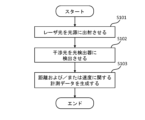
- FIG. 3 is a flowchart schematically showing an example of a measurement operation performed by the processing circuit.
- FIG. 4A is a diagram for explaining the flow of a plurality of lights occurring within the measuring device shown in FIG. 1.
- FIG. FIG. 4B is a diagram for explaining optical path lengths of a plurality of light flows occurring within the measuring device shown in FIG. 1.
- FIG. FIG. 5 is a block diagram schematically showing the configuration of a measuring device according to a comparative example.
- FIG. 6A is a diagram for explaining the flow of a plurality of lights occurring within the measuring device shown in FIG. 5.
- FIG. FIG. 6B is a diagram for explaining optical path lengths of a plurality of light flows occurring within the measuring device shown in FIG. 5.
- FIG. 7A is a diagram schematically showing an example of a spectrum of a detection signal in Embodiment 1.
- FIG. 7B is a diagram schematically showing an example of a spectrum of a detection signal in a comparative example.
- FIG. 8 is a block diagram schematically showing the configuration of a measuring device according to exemplary embodiment 2 of the present disclosure.
- FIG. 9 is a block diagram schematically showing the configuration of a measuring device according to exemplary embodiment 3 of the present disclosure.
- FIG. 10 is a block diagram schematically showing the configuration of a measuring device according to exemplary embodiment 4 of the present disclosure.
- FIG. 11 is a block diagram schematically showing the configuration of a measuring device according to exemplary embodiment 5 of the present disclosure.
- FIG. 12 is a block diagram schematically showing the configuration of a measuring device according to exemplary embodiment 6 of the present disclosure.
- FIG. 13 is a block diagram schematically showing the configuration of a measuring device according to exemplary embodiment 7 of the present disclosure.
- all or part of a circuit, unit, device, member, or section, or all or part of a functional block in a block diagram may be, for example, a semiconductor device, a semiconductor integrated circuit (IC), or a large scale integration (LSI). ) may be implemented by one or more electronic circuits.
- An LSI or IC may be integrated into one chip, or may be configured by combining a plurality of chips.
- functional blocks other than the memory element may be integrated into one chip.
- it is called LSI or IC, but the name changes depending on the degree of integration, and may be called system LSI, VLSI (very large scale integration), or ULSI (ultra large scale integration).
- a field programmable gate array (FPGA), which is programmed after the LSI is manufactured, or a reconfigurable logic device that can reconfigure the connections inside the LSI or set up circuit sections inside the LSI can also be used for the same purpose.
- FPGA field programmable gate array
- the functions or operations of all or part of a circuit, unit, device, member, or section can be performed by software processing.
- the software is recorded on one or more non-transitory storage media such as ROM, optical disk, hard disk drive, etc., and when the software is executed by a processor, the functions specified by the software are executed. It is executed by a processor and peripheral devices.
- a system or apparatus may include one or more non-transitory storage media on which software is recorded, a processor, and required hardware devices, such as interfaces.
- light includes not only visible light (wavelength of about 400 nm to about 700 nm) but also electromagnetic waves including ultraviolet light (wavelength of about 10 nm to about 400 nm) and infrared light (wavelength of about 700 nm to about 1 mm). means.
- ultraviolet light is also referred to as “ultraviolet light” and infrared light is also referred to as “infrared light.”
- Patent Document 1 discloses a laser radar device that measures the distance from the device to the object by irradiating an object to be measured with light and receiving reflected light generated by the irradiation.
- Patent Document 2 discloses a distance measuring device using FMCW technology that accurately measures the distance from the device to an object by removing the influence of nonlinear chirp of laser light.
- Non-Patent Document 1 discloses a distance measuring device using FMCW technology that enables miniaturization of the device by configuring an optical system on-chip.
- FMCW-LiDAR technology has been developed that has both a wide dynamic range and high resolution in terms of distance, is less susceptible to external disturbances, and can detect the speed of objects moving at high speed.
- the spot diameter of the light that illuminates the object can be made relatively small, making it possible to more accurately obtain measurement data on the object.
- a measurement device using FMCW-LiDAR technology includes a light source and an interference optical system.
- the interference optical system separates laser light emitted from a light source into reference light and irradiation light, and generates interference light by superimposing the reference light and reflected light generated when an object is irradiated with the irradiation light. By detecting the interference light with a photodetector, measurement data of the object can be obtained.
- the intensity of the laser light emitted to the outside from the measuring device is classified into classes according to, for example, JIS (Japanese Industrial Standards) C6802 "Safety Standards for Laser Products.” It is desirable that the intensity of the laser beam emitted to the outside satisfies class 1 from the viewpoint of eye safety, that is, eye safety.
- the present inventor has conceived of a measuring device according to an embodiment of the present disclosure that can reduce such a possibility.
- the measuring device according to this embodiment using FMCW-LiDAR technology includes a light source, an interference optical system, a first housing that houses the light source and the interference optical system, and a second housing that houses the first housing. Equipped with.
- the measurement device according to this embodiment reduces the possibility that unintended light from the light source and the interference optical system leaks to the outside of the measurement device, compared to a configuration that does not include the first housing that houses the light source and the interference optical system. can do.
- a measurement device according to an embodiment of the present disclosure will be described.
- the measurement device includes a light source that emits light, and an interference optical system that separates the light emitted from the light source into a reference light and an irradiation light for irradiating an object, the measurement device comprising: an interference optical system that generates interference light by causing reflected light generated when light is reflected by the object and the reference light to interfere; an output fiber that is connected to the interference optical system and guides the irradiation light;
- the apparatus includes: an optical element connected to the output fiber and emitting the irradiation light; a first housing housing the light source and the interference optical system; and a second housing housing the first housing. The output fiber is directly pulled out from the first housing.
- This measurement device can reduce the possibility of unintended light leaking to the outside. Furthermore, since the output fiber is directly drawn out from the first casing, it is possible to reduce noise in the spectrum of the detection signal.
- the measuring device according to the second item is the measuring device according to the first item, in which the output fiber is drawn out from the first casing and the second casing.
- the optical element is arranged outside the second housing.
- the measuring device is the measuring device according to the first item, in which the output fiber is drawn out from the first casing.
- the optical element is arranged outside the first housing and inside the second housing.
- the second housing includes a light-transmitting window that transmits the irradiation light.
- the measuring device is the measuring device according to any one of the first to third items, in which the optical element emits the irradiation light and receives the reflected light.
- the interference optical system includes a first optical splitter, a second optical splitter, and a circulator or a third optical splitter.
- the first optical splitter separates and outputs the reference light and the irradiation light, inputs the outputted reference light to the second optical splitter, and inputs the outputted irradiation light to the circulator or the third light. input to the splitter.
- the circulator or the third optical splitter outputs the irradiation light from the first optical splitter, inputs the irradiation light into the optical element, outputs the reflected light from the optical element, and outputs the reflected light from the optical element. is input to the second optical splitter.
- the second optical splitter generates the interference light by causing the reflected light from the circulator or the third optical splitter to interfere with the reference light from the first optical splitter.
- interference light can be generated by using a first optical splitter, a second optical splitter, and a circulator, or by using a first optical splitter, a second optical splitter, and a third optical splitter. .
- the optical path length of the first path from the first optical splitter to the photodetector that detects the interference light is d 1
- the optical path length of the second path from the second optical splitter to the optical element is d 2
- the optical path length of the third path from the optical element to the photodetector is d 3
- the first optical splitter When the optical path length of the fourth path from the noise optical path of the circulator or the third optical splitter to the photodetector is d4 ,
- the measuring device is the measuring device according to any one of the first to fifth items, the measuring device being connected to a signal fiber that guides the interference light from the interference optical system, and the signal fiber,
- the apparatus further includes a photodetector that detects the interference light.
- interference light can be detected by a photodetector.
- the measuring device according to the seventh item is the measuring device according to the sixth item, wherein the photodetector is arranged outside the first casing and inside the second casing.
- the measuring device is the measuring device according to the seventh item, in which the signal fiber includes two connectors and a receptacle for connecting the two connectors.
- the receptacle is attached to the first housing.
- the photodetector can be attached and detached.
- the measuring device according to the ninth item is the measuring device according to the sixth item, in which the photodetector is arranged inside the first casing.
- the signal fiber that connects the photodetector and the interference optical system does not need to include a connector and a receptacle, so the components of the measurement device can be simplified and the cost of parts can be kept low.
- the measuring device according to the tenth item is the measuring device according to the ninth item, in which the interference optical system and the photodetector are configured on-chip.
- the measuring device is the measuring device according to the sixth item, which comprises a processing circuit that controls the operation of the light source and the operation of the photodetector, and processes the signal output from the photodetector.
- the device further includes a processing circuit located outside the first casing and inside the second casing.
- the measuring device according to the twelfth item is the measuring device according to the eleventh item, in which the light source can change the frequency of the light over time.
- the FMCW-LiDAR technology makes it possible to measure the distance and/or speed of an object.
- the measuring device includes a light source that emits light, and an interference optical system that separates the light emitted from the light source into a reference light and an irradiation light for irradiating an object, the measurement device comprising: an interference optical system that generates interference light by causing reflected light generated when light is reflected by the object and the reference light to interfere; an output fiber that is connected to the interference optical system and guides the irradiation light; an optical element that is connected to the output fiber and emits the irradiation light; a photodetector that detects the interference light; a first housing that accommodates the light source and the interference optical system; and the first housing.
- a processing circuit that controls the operation of the light source and the photodetector and processes the signal output from the photodetector, the processing circuit being outside the first case and the above-mentioned photodetector; and a processing circuit disposed inside the second casing.
- This measurement device can reduce the possibility of unintended light leaking to the outside. Furthermore, heat generated from the processing circuit can be effectively released to the outside via the second casing.
- the measuring device according to the fourteenth item is the measuring device according to the thirteenth item, wherein the output fiber is one continuous optical fiber.
- noise can be reduced in the spectrum of the detection signal using one continuous optical fiber.
- the measuring device according to the fifteenth item is the measuring device according to the thirteenth or fourteenth item, in which the light source can change the frequency of the light over time.
- the FMCW-LiDAR technology makes it possible to measure the distance and/or speed of an object.
- the measurement device includes a light source that emits light, and an interference optical system that separates the light emitted from the light source into a reference light and an irradiation light for irradiating an object, the measurement device comprising: an interference optical system that generates interference light by causing reflected light generated when light is reflected by the object and the reference light to interfere; an output fiber that is connected to the interference optical system and guides the irradiation light;
- the apparatus includes: an optical element connected to the output fiber and emitting the irradiation light; a first housing housing the light source and the interference optical system; and a second housing housing the first housing.
- the output fiber is arranged inside the first housing.
- the optical element is arranged inside the first housing.
- the first housing includes a first light-transmitting window that transmits the irradiation light.
- the second housing includes a second light-transmitting window that transmits the irradiation light.
- This measurement device can reduce the possibility of unintended light leaking to the outside. Furthermore, since there is no need for a fiber pull-out section for drawing out the output fiber, the components of the measuring device can be simplified and the cost of parts can be kept low.
- FIG. 1 is a block diagram schematically showing the configuration of a measuring device according to exemplary embodiment 1 of the present disclosure.
- a person is shown as an object 10 to be measured.
- the object 10 may be any object other than a person, such as a vehicle or a building.
- the measuring device 100A further includes a first housing 70a that houses the light source 20, an interference optical system 30, a photodetector 50, a processing circuit 60, and a memory 62, and a second housing that houses the first housing 70a. 70b.
- the thick lines shown in FIG. 1 represent optical fibers connecting two components to each other.
- Solid lines with arrows shown in FIG. 1 represent signal transmission and reception.
- the dashed lines with arrows shown in FIG. 1 represent the flow of light.
- Some components and the remaining components of the measuring device 100A according to the first embodiment may be manufactured and/or sold separately. The some components may be, for example, at least one of the photodetector 50, the processing circuit 60, and the memory 62.
- the measuring device 100A emits irradiation light 20L2 for irradiating the object 10, and receives reflected light 20L3 generated by irradiating the object 10 with the irradiation light 20L2, thereby measuring the distance and/or speed of the object 10. It is possible to obtain measurement data related to In the measurement device 100A according to the first embodiment, unintended light from the light source 20 and the interference optical system 30 is transmitted to the measurement device 100A, compared to a configuration that does not include the first housing 70a that houses the light source 20 and the interference optical system 30. The possibility of leakage to the outside can be reduced.
- the components of the measuring device 100A will be explained below.
- the light source 20 emits laser light 20L0.
- the light source 20 can change the frequency of the laser beam 20L0.
- the frequency can be changed over time in a constant time period, for example in a triangular wave shape or a sawtooth shape.
- the time period may be, for example, 1 ⁇ sec or more and 10 msec or less.
- the time period may vary.
- the frequency change width may be, for example, 100 MHz or more and 1 THz or less.
- the wavelength of the laser beam 20L0 may be included in the near-infrared wavelength range of, for example, 700 nm or more and 2000 nm or less.
- Sunlight has near-infrared light and visible light, and the amount of near-infrared light is smaller than the amount of visible light. Therefore, if near-infrared light is used as the laser light 20L0, the influence of sunlight as noise can be reduced.
- the wavelength of the laser beam 20L0 does not necessarily need to be included in the wavelength range of near-infrared light.
- the wavelength of the laser beam 20L0 may be included in the wavelength range of visible light from 400 nm to 700 nm, or may be included in the wavelength range of ultraviolet light.
- the light source 20 may include, for example, a distributed feedback (DFB) laser diode or an external cavity (EC) laser diode.
- DFB distributed feedback
- EC external cavity
- These laser diodes are inexpensive and small, capable of single mode oscillation, and can modulate the frequency of the laser light 20L0 according to the amount of current applied. If a laser diode capable of emitting a high-intensity laser beam exceeding class 1 is used as the light source 20, the frequency of the laser beam 20L0 can be stably modulated. However, the intensity of the laser beam 20L0 emitted from the light source 20 is adjusted so that the intensity of the laser beam emitted to the outside satisfies class 1.
- DFB distributed feedback
- EC external cavity
- the light source 20 is connected to the first optical splitter 32a.
- An attenuator may be disposed between the light source 20 and the first optical splitter 32a to adjust the intensity of the laser beam 20L0.
- the interference optical system 30 includes a first optical splitter 32a, a second optical splitter 32b, and an optical circulator 34.
- the first optical splitter 32a separates the laser light 20L0 emitted from the light source 20 into a reference light 20L1 and an irradiation light 20L2 for irradiating the object 10, and outputs the separated laser light 20L0.
- the intensity of the reference light 20L1 may be, for example, 1% or more and 10% or less of the intensity of the laser beam 20L0 input to the first optical splitter 32a.
- the first optical splitter 32a inputs the outputted reference light 20L1 to the second optical splitter 32b, and inputs the outputted irradiation light 20L2 to the optical circulator 34.
- the first optical splitter 32a is connected to the second optical splitter 32b and the optical circulator 34.
- the optical circulator 34 outputs the irradiated light 20L2 from the first optical splitter 32a and inputs the irradiated light 20L2 to the optical element 40 via the output fiber 42.
- the optical circulator 34 further outputs reflected light 20L3 generated when the irradiated light 20L2 is reflected by the object 10, and inputs the reflected light 20L3 to the second optical splitter 32b.
- the optical circulator 34 is connected to the first optical splitter 32a, the second optical splitter 32b, and the optical element 40.
- the second optical splitter 32b inputs interference light 20L4, which is obtained by superimposing and interfering the reference light 20L1 and the reflected light 20L3, to the photodetector 50 via the two signal fibers 52.
- the second optical splitter 32b is connected to the first optical splitter 32a, the optical circulator 34, and the photodetector 50.
- optical element 40 emits the irradiated light 20L2 from the optical circulator 34 to the outside via the output fiber 42.
- the optical element 40 further receives the reflected light 20L3 and inputs the reflected light 20L3 to the optical circulator 34 via the output fiber 42.
- the optical element 40 may be, for example, a collimator lens that collimates the irradiated light 20L2.
- collimator lens collimates the irradiated light 20L2.
- collimator lens collimates the irradiated light 20L2.
- colllimating means not only the case where the irradiated light 20L2 is made into parallel light, but also the case where the spread of the irradiated light 20L2 is reduced.
- the optical element 40 may be a condenser lens that focuses the irradiated light 20L2, or may be a diffuser lens that diffuses the irradiated light 20L2.
- the optical element 40 may be a diffraction grating that outputs the irradiated light 20L2 to the outside as 0th-order diffracted light and/or ⁇ Nth-order diffracted light (N is a natural number).
- N is a natural number
- the measuring device 100A may further include an optical deflector that changes the direction of the irradiation light 20L2 emitted from the optical element 40.
- the optical deflector can be, for example, one selected from the group consisting of a galvano scanner, a polygon mirror, a MEMS scanner, a phase modulation scanner, a refractive index modulation scanner, and a wavelength modulation scanner.
- the path of the irradiated light 20L2 from the interference optical system 30 to the object 10 and the path of the reflected light 20L3 from the object 10 to the interference optical system 30 overlap with each other.
- the configuration of the measuring device 100A can be simplified and stable measurement can be achieved.
- the output fiber 42 is one continuous optical fiber, and guides the irradiated light 20L2 from the optical circulator 34 and the reflected light 20L3 from the optical element 40.
- Output fiber 42 is connected to interference optics 30 , more specifically optical circulator 34 , and optical element 40 is connected to output fiber 42 .
- the output fiber 42 is provided with a connector 42a at one of its two opposite ends.
- Optical element 40 includes a receptacle 40a for connecting a connector 42a of output fiber 42. Since the optical element 40 and the output fiber 42 are removable, manufacturing and maintenance of the measuring device 100A is facilitated.
- output fiber 42 may be connected directly to optical element 40, for example by a coupling lens.
- a type in which the output fiber 42 is connected to the optical element 40 by such a method is called a pigtail type.
- the photodetector 50 detects the interference light 20L4 from the second optical splitter 32b via the two signal fibers 52, and outputs a signal according to the intensity of the interference light 20L4.
- Photodetector 50 includes one or more photodiodes. The photodiode outputs a signal corresponding to the intensity of the interference light 20L4.
- Photodetector 50 may include a preamplifier to amplify the signal.
- the photodetector 50 is a balanced photodiode with two ports. Since the photodetector 50 detects the difference between the lights input from the two ports, common mode noise can be reduced. Note that the photodetector 50 may be a photodiode with one port other than a balanced photodiode.
- ⁇ Signal fiber 52> The two signal fibers 52 equally separate and guide the interference light 20L4 from the second optical splitter 32b. Each signal fiber 52 is connected to the second optical splitter 32b, and the photodetector 50 is connected to the two signal fibers 52. Each signal fiber 52 includes a connector 52a at one of its two opposite ends.
- the photodetector 50 includes two receptacles 50a for connecting the connectors 52a of the two signal fibers 52, respectively.
- Each signal fiber 52 includes two connectors 52b and a receptacle 52c between the two ends.
- the receptacle 52c is a component located between the two connectors 52b and for connecting the two connectors 52b.
- Receptacle 52c is attached to first housing 70a.
- the two connectors 52b and receptacles 52c allow the portion of each signal fiber 52 to be connected to the photodetector 50 and the portion connected to the second optical splitter 32b to be attached or detached. As a result, manufacturing and maintenance of the measuring device 100A becomes easier.
- each signal fiber 52 may be connected directly to a photodetector 50, for example by a coupling lens.
- Each signal fiber 52 like output fiber 42, may be a single continuous optical fiber. If the photodetector 50 is a photodiode with one port, the number of signal fibers 52 is one.
- the processing circuit 60 includes a control circuit 60a, a drive circuit 60b, and a signal processing circuit 60c.
- the control circuit 60a controls the operation of the drive circuit 60b, the signal processing circuit 60c, and the photodetector 50.
- each operation of the control circuit 60a, drive circuit 60b, and signal processing circuit 60c may be described as the operation of the processing circuit 60.
- the drive circuit 60b drives the light source 20. It can also be said that the control circuit 60a controls the operation of the light source 20 via the drive circuit 60b.
- the signal processing circuit 60c processes the signal output from the photodetector 50 using FMCW-LiDAR technology.
- the processing circuit 60 generates and outputs measurement data regarding the distance and/or speed of the object 10 based on the signal.
- the signal processing circuit 60c performs Fourier transform on the time waveform of the detection signal to generate data indicating its frequency spectrum, and generates and outputs measurement data based on the data.
- the signal processing circuit 60c inputs the output measurement data to a display (not shown), and the display may display information regarding the distance and/or speed of the object 10.
- the signal processing circuit 60c may input the output measurement data to another device, and the other device may perform a specific operation based on the measurement data.
- the other device may be, for example, a vehicle or an industrial robot.
- the measuring device 100A includes a processing device including a processing circuit 60 and a memory 62.
- Processing circuit 60 and memory 62 may be integrated on one circuit board or may be provided on separate circuit boards.
- the control circuit 60a, drive circuit 60b, and signal processing circuit 60c included in the processing circuit 60 may be distributed over multiple circuits.
- the processing device, or a portion thereof, may be located remotely from other components and may control operation of the light source 20 and photodetector 50 via a wired or wireless communication network.
- the first housing 70a accommodates the light source 20 and the interference optical system 30 for the following reasons.
- the light source 20 and the first optical splitter 32a are connected by an optical fiber.
- a laser diode capable of emitting high-intensity laser light may be used as the light source 20.
- the laser beam with an intensity exceeding class 1 is emitted from the light source 20
- the light source 20 emits a laser beam with an intensity that satisfies Class 1
- the object will be reflected by the leaked light and the measurement data of the object will not be accurate. may not be available.
- the intensity of the irradiation light 20L2 emitted from the optical element 40 is I out
- the intensity of the irradiation light 20L2 output from the optical circulator 32a is I rad1 .
- L ele is sufficiently small (for example, several tens of dB or more) compared to I out , so it is possible to emit the irradiation light 20L2 from the optical element 40 with an intensity close to the upper limit that satisfies class 1.
- the measuring device 100A In the measuring device 100A according to the first embodiment, unintended light from inside the light source 20 and the interference optical system 30 is transmitted to the measuring device 100A, compared to a configuration that does not include the first housing 70a that houses the light source 20 and the interference optical system 30. The possibility of leakage to the outside can be reduced. When the first housing 70a accommodates the light source 20 and the interference optical system 30 in a hermetically sealed state, the possibility that unintended light leaks to the outside of the measuring device 100A can be effectively reduced.
- the first casing 70a and the second casing 70b each include a first fiber drawing part 72a and a second fiber drawing part 72b for drawing out the output fiber 42.
- One continuous output fiber 42 is drawn out from the first casing 70a and the second casing 70b via the first fiber drawing part 72a and the second fiber drawing part 72b.
- the first fiber pull-out section 72a and the second fiber pull-out section 72b have a structure that allows continuous output fibers 42 to be directly drawn out from the first casing 70a and the second casing 70b, respectively.
- a connector and a receptacle for attaching and detaching the output fiber 42 are not used in the first fiber pull-out part 72a and the second fiber pull-out part 72b. Therefore, in the output fiber 42, almost no reflection of the irradiated light 20L2 occurs when the irradiated light 20L2 is guided. The effect of almost no reflection of the irradiated light 20L2 will be described later.
- the fiber pull-out portions 72a, 72b may be rubber bushes, for example. When a hole is made in the rubber bushing and the output fiber 42 is passed through the hole, the gap between the outer covering portion of the output fiber 42 and the hole in the rubber bushing is filled by the elasticity of the rubber.
- the fiber pull-out parts 72a and 72b may be, for example, covers that close gaps between holes made in the casings 70a and 70b and outer coatings of the output fibers that pass through the holes.
- the optical element 40 is connected to the output fiber 42 drawn out from the housings 70a, 70b via the fiber drawing parts 72a, 72b. Therefore, the optical element 40 is arranged outside the second housing 70b. With such a configuration, the direction of the irradiation light 20L2 emitted from the optical element 40 can be easily adjusted depending on the position of the object 10, independently of the installation direction of the measuring device 100A.
- the first casing 70a further includes a wiring lead-out portion 74 for pulling out wiring for sending signals from the drive circuit 60b to the light source 20.
- the drive circuit 60b and the light source 20 are electrically connected by wiring.
- Wiring lead-out portion 74 may be, for example, an electrical connector.
- the first housing 70a can accommodate the light source 20 and the interference optical system 30 in a sealed state without any gaps. Furthermore, the first housing 70a and the second housing 70b allow the irradiated light 20L2 to be extracted to the outside via the output fiber 42. In this way, it is possible to simultaneously block leakage light from the light source 20 and the interference optical system 30 and extract the irradiation light 20L2 to the outside. Since the output fiber 42 is an optical fiber directly pulled out from the first housing 70a and the second housing 70b, the irradiated light 20L2 is guided within the output fiber 42 with almost no reflection.
- the photodetector 50 and the processing circuit 60 are arranged outside the first housing 70a and inside the second housing 70b.
- Photodetector 50 may include components that do not generate much heat, such as a photodiode and a preamplifier.
- the processing circuit 60 may include an arithmetic element such as a CPU or an FPGA that generates a relatively large amount of heat.
- the heat generated from the processing circuit 60 cannot be effectively released to the outside.
- the operation of the processing circuit 60 may become unstable.
- the temperature inside the first housing 70a increases, the length of the optical fiber inside the first housing 70a changes on the order of micrometers. As a result, depending on the distance range and distance resolution in which the distance and/or velocity of the object 10 can be measured, errors may occur in the measurement data of the object 10.
- the processing circuit 60 is placed outside the first housing 70a, so that the heat generated from the processing circuit 60 during operation is transferred to the second housing 70b. can be effectively released to the outside through
- the second housing 70b may include a ventilation hole or a fan for heat radiation. Since the heat emitted from the processing circuit 60 can be effectively released to the outside, the processing circuit 60 can be operated more stably, and fluctuations in the length of the optical fiber in the first housing 70a can be suppressed. Thus, measurement data of the object 10 can be accurately acquired. Furthermore, since the photodetector 50 and the processing circuit 60 are arranged outside the first housing 70a, maintenance of the photodetector 50 and the processing circuit 60 is easy.
- FMCW-LiDAR technology Next, the FMCW-LiDAR technology will be briefly explained with reference to FIG. Details of the FMCW-LiDAR technology are disclosed in, for example, Non-Patent Document 1.
- FIG. 2 is a diagram schematically showing temporal changes in the frequencies of the reference light 20L1 and the reflected light 20L3 when the object 10 is stationary.
- the solid line represents the reference light 20L1
- the broken line represents the reflected light 20L3.
- the frequency of the reference light 20L1 shown in FIG. 2 repeatedly changes over time in the form of a triangular wave. That is, the frequency of the reference light 20L1 repeats up-chirp and down-chirp. The increase in frequency during the up-chirp period and the decrease in frequency during the down-chirp period are equal to each other.
- the frequency of the reflected light 20L3 is shifted in the positive direction along the time axis compared to the frequency of the reference light 20L1.
- the amount by which the time of the reflected light 20L3 is shifted is equal to the time it takes for the irradiation light 20L2 to be emitted from the measuring device 100A, reflected by the object 10, and returned as the reflected light 20L3.
- interference light 20L4 obtained by superimposing and interfering with reference light 20L1 and reflected light 20L3 has a frequency corresponding to the frequency difference between the frequency of reflected light 20L3 and the frequency of reference light 20L1.
- the double-headed arrow shown in FIG. 2 represents the frequency difference between the two.
- the photodetector 50 outputs a signal indicating the intensity of the interference light 20L4. This signal is called a beat signal.
- the frequency of the beat signal, ie, the beat frequency is equal to the above frequency difference.
- Processing circuit 60 can generate measurement data regarding the distance and/or velocity of object 10 from the beat frequency.
- the beat frequency during the up-chirp period and the beat frequency during the down-chirp period are equal to each other.
- the increase/decrease in the frequency of light during the up-chirp period or the down-chirp period is ⁇ f
- the time required for the change of ⁇ f is ⁇ t
- the speed of light is c
- the optical path length of the reference light 20L1 the optical path length of the irradiated light 20L2
- the optical path of the reflected light 20L3 Assuming that the difference from the total length is 2d, the beat frequency f beat in the up-chirp period or the down-chirp period is expressed by the following equation (1).
- the beat frequency f beat in equation (1) is determined by the time rate of change in frequency ⁇ f/ ⁇ t, and the time it takes for the irradiation light 20L2 to be emitted from the measurement device 100A to the outside and be reflected by the object 10 and return as the reflected light 20L3. It is obtained by multiplying by (2d/c).
- the frequency of the reflected light 20L3 undergoes a Doppler shift in the positive or negative direction along the frequency axis compared to the frequency of the reference light 20L1.
- the beat frequency during the up-chirp period and the beat frequency during the down-chirp period are different from each other.
- the processing circuit 60 can generate measurement data regarding the speed and distance of the object 10 from the frequency difference and average of these beat frequencies, respectively.
- FIG. 3 is a flowchart schematically showing an example of a measurement operation performed by the processing circuit 60.
- the processing circuit 60 executes the operations from steps S101 to S103 shown in FIG.
- the processing circuit 60 causes the light source 20 to emit laser light 20L0 whose frequency changes over time.
- the control circuit 60a causes the drive circuit 60b to drive the light source 20, and causes the light source 20 to emit laser light 20L0 whose frequency changes over time.
- the processing circuit 60 causes the photodetector 50 to detect the interference light 20L4.
- the photodetector 50 outputs a signal corresponding to the intensity of the interference light 20L4.
- the control circuit 60a causes the photodetector 50 to detect the interference light 20L4.
- the processing circuit 60 generates measurement data regarding the distance and/or speed of the object 10 based on the signal output from the photodetector 50. Specifically, the control circuit 60a causes the signal processing circuit 60c to generate measurement data based on the signal output from the photodetector 50.
- the above-described operation of the processing circuit 60 makes it possible to measure the distance and/or speed of the object 10.
- FIG. 4A is a diagram for explaining the flow of a plurality of lights that occur within the measuring device 100A shown in FIG. 1.
- the signal fiber 52 connecting the second optical splitter 32b and the photodetector 50 is shown as one optical fiber.
- the optical fiber that connects both may be shown as one optical fiber.
- the dashed lines with arrows shown in FIG. 4A represent the flow of light.
- a plurality of light flows ⁇ to ⁇ occur within the measurement device 100A.
- the light flow ⁇ is the flow of the reference light 20L1 from the first optical splitter 32a to the photodetector 50.
- the light flow ⁇ is a flow in which the irradiated light 20L2 reaches the object 10 from the first optical splitter 32a, and the reflected light 20L3 flows from the object 10 to the photodetector 50.
- the light flows ⁇ and ⁇ cause noise in the detection signal.
- the light flow ⁇ is a flow in which a part of the irradiated light 20L2 is reflected from the first optical splitter 32a, is reflected by the optical element 40, and reaches the photodetector 50. Such reflection occurs at receptacle 40a of optical element 40 shown in FIG.
- the light flow ⁇ is a flow in which the other part of the irradiated light 20L2 travels from the first optical splitter 32a to the photodetector 50 via the noise optical path inside the optical circulator 34.
- the noise light path is considered to be a path passing through the optical circulator 34, more specifically, a path along which the leaked light of the irradiation light 20L2 toward the optical element 40 in the optical circulator 34 travels while being subjected to multiple scattering inside.
- FIG. 4B is a diagram for explaining optical path lengths from ⁇ to ⁇ of a plurality of light flows occurring within the measuring device 100A shown in FIG.
- the second optical path length of the second path from the first optical splitter 32a to the optical element 40 is assumed to be d2 .
- a fourth optical path length d is defined as the optical path length of the fourth path from the first optical splitter 32a to the photodetector 50 via the noise optical path inside the interference optical system 30, more specifically, inside the optical circulator 34. Set it to 4 .
- the round trip distance between the optical element 40 and the object 10 is assumed to be 2L.
- the distance L is the distance from the receptacle 40a of the optical element 40 shown in FIG. 1 to the location where the object 10 is irradiated with the irradiation light 20L2. Therefore, when the object 10 contacts the optical element 40, the distance L corresponds to the length of the optical element 40.
- the optical path length of the light flow ⁇ is d 1
- the optical path length of the light flow ⁇ is d 2 +d 3 +2L
- the optical path length of the light flow ⁇ is d 2 +d 3
- the optical path length of the light flow ⁇ is d 4 .
- the frequency of the beat signal caused by the reflected light 20L3 reflected by the object 10 is expressed by the following equation (2).
- in equation (2) is the optical path length difference between the light flow ⁇ and the light flow ⁇ .
- the frequency f opt of the beat signal caused by the light reflected by the optical element 40 is expressed by the following equation (3).
- in equation (3) is the optical path length difference between the light flow ⁇ and the light flow ⁇ .
- the frequency f cir of the beat signal caused by multiple scattered light generated inside the optical circulator 34 is expressed by the following equation (4).
- in equation (4) is the optical path length difference between the light flow ⁇ and the light flow ⁇ .
- Japanese Patent Application No. 2022-010910 filing date: January 2022). 27th is explained in detail. The entire disclosure content of Japanese Patent Application No. 2022-010910 is incorporated herein.
- the output fiber 42 is not directly pulled out from the first housing 70a and the second housing 70b, but instead has a connector and a connector between the two ends located on opposite sides. Problems that arise when using an output fiber with a receptacle will be explained using a measuring device according to a comparative example.
- FIG. 5 is a block diagram schematically showing the configuration of a measuring device according to a comparative example.
- the measuring device 90 shown in FIG. 5 differs from the measuring device 100A shown in FIG. 1 in that the measuring device 90 includes an output fiber 43 shown in FIG. 5 instead of the output fiber 42 shown in FIG. 1.
- the output fiber 43 includes a first connector 43a at one of its two opposite ends.
- the first connector 43a is connected to the receptacle 40a of the optical element 40.
- the output fiber 43 further includes two second connectors 43b and a first receptacle 43c between the two ends.
- the first receptacle 43c is a component located between the two second connectors 43b and for connecting the two second connectors 43b.
- the first receptacle 43c is attached to the first housing 70a.
- the output fiber 43 further includes two third connectors 43d and a second receptacle 43e between the two ends.
- the second receptacle 43e is a component located between the two third connectors 43d and for connecting the two third connectors 43d.
- the second receptacle 43e is attached to the second housing 70b.
- the portion that connects to the optical element 40, the portion that connects to the optical circulator 34, and the portion located between these two portions can be attached and detached, making manufacturing and maintenance of the measuring device 90 easy. become.
- the output fiber 43 is not an optical fiber directly drawn out from the first housing 70a and the second housing 70b, when guiding the irradiation light 20L2, the output fiber 43 is irradiated by the first receptacle 43c and the second receptacle 43e. Reflection of the light 20L2 occurs.
- FIG. 6A is a diagram for explaining the flow of a plurality of lights that occur within the measuring device 90 shown in FIG. 5.
- the measurement device 90 in addition to the light flows ⁇ to ⁇ , the measurement device 90 produces light flows ⁇ ′ and ⁇ ′′ that cause noise in the detection signal.
- the light flows ⁇ and ⁇ are caused by one part and another part of the irradiated light 20L2, respectively.
- the light flow ⁇ ' is a flow in which still another part of the irradiated light 20L2 is reflected from the first optical splitter 32a and reaches the photodetector 50 by the first receptacle 43c.
- the light flow ⁇ '' is a flow in which still another part of the irradiated light 20L2 is reflected from the first optical splitter 32a and reaches the photodetector 50 by the second receptacle 43e.
- FIG. 6B is a diagram for explaining optical path lengths of a plurality of light flows occurring within the measuring device 90 shown in FIG. 5.
- d21 be the fifth optical path length of the fifth path from the first optical splitter 32a to the first receptacle 43c.
- the sixth optical path length of the sixth path from the first receptacle 43c to the photodetector 50 is assumed to be d31 .
- d22 be the seventh optical path length of the seventh path from the first optical splitter 32a to the second receptacle 43e.
- the eighth optical path length of the eighth path from the second receptacle 43e to the photodetector 50 is assumed to be d32 .
- the optical path length of the light flow ⁇ ' is d 21 +d 31
- the optical path length of the light flow ⁇ '' is d 22 +d 32 .
- the frequency f r1 of the beat signal caused by the light reflected by the first receptacle 43c is expressed by the following equation (5).
- in equation (5) is the optical path length difference between the light flow ⁇ ' and the light flow ⁇ .
- the frequency f r2 of the beat signal caused by the light reflected by the second receptacle 43e is expressed by the following equation (6).
- in equation (6) is the optical path length difference between the light flow ⁇ '' and the light flow ⁇ .
- the first housing 70a can accommodate the light source 20 and the interference optical system 30 in a sealed state without any gaps. Furthermore, the first housing 70a and the second housing 70b allow the irradiated light 20L2 to be extracted to the outside via the output fiber 43. In this way, it is possible to simultaneously block leakage light from the light source 20 and the interference optical system 30 and extract the irradiation light 20L2 to the outside.
- the output fiber 43 is not an optical fiber directly pulled out from the first housing 70a and the second housing 70b, but includes connectors 43b, 43d and receptacles 43c, 43e, when guiding the irradiated light 20L2, , a part of the irradiated light 20L2 may be reflected by the receptacles 43c and 43e.
- FIGS. 7A and 7B are diagrams schematically showing examples of spectra of detection signals in Embodiment 1 and Comparative Example, respectively.
- the vertical axis represents the intensity of the detection signal
- the horizontal axis represents the frequency.
- the frequency is greater than or equal to zero and corresponds to the distance from the optical element 40 to the object 10.
- the distance from the optical element 40 to the object 10 can be measured by setting the receptacle 40a of the optical element 40 shown in FIG. 1 to 0 m. Even when the object 10 contacts the optical element 40, the distance from the optical element 40 to the object 10 corresponds to the length of the optical element 40, so the peaks ⁇ and ⁇ do not overlap with each other.
- f opt ⁇ 0 Hz
- a frequency range whose frequency is lower than f opt is not used as a frequency range corresponding to a distance range in which ranging and/or speed measurement of the object 10 can be performed.
- f opt 0 Hz
- there is no such unused frequency range so the distance range in which distance measurement and/or speed measurement of the object 10 can be performed can be maximized.
- peaks ⁇ , ⁇ , and ⁇ appear in the spectrum of the detection signal due to the light flows ⁇ , ⁇ , and ⁇ , respectively.
- the peak frequency of peak ⁇ is f obj
- the peak frequency of peak ⁇ is f opt
- the peak frequency of peak ⁇ is f cir .
- the frequencies f obj , f opt , and f cir are different from each other due to the difference in the optical path length of the light flows ⁇ to ⁇ . Peaks ⁇ and ⁇ are noise. If the frequency f obj is not near the frequency f cir , measurement data of the object 10 can be accurately acquired.
- a frequency range other than the vicinity of the frequency f cir corresponds to a distance range in which distance measurement and/or speed measurement of the object 10 can be performed.
- the frequency range near the frequency f cir may vary depending on the environment in which the distance measurement and/or speed measurement of the object 10 is performed.
- the frequency range near the frequency f cir corresponds to a distance range within 1 m, 10 cm, or 1 cm from the distance corresponding to the frequency f cir , for example.
- frequency f obj may overlap frequency f r1 or f r2 . In this way, the peaks ⁇ and ⁇ '' narrow the distance range in which distance measurement and/or speed measurement of the object 10 can be performed.
- frequencies fobj, fopt , fr1 , fr2 , and fcir may vary.
- the frequencies f obj , f r1 , f r2 , and f cir are It appears on the higher frequency side than f opt . Therefore, frequency f obj may overlap frequency f r1 or f r2 .
- the condition of equation (7) is satisfied, if the output fiber 42 in the first embodiment is used, the measurement of the object 10 will be difficult if the frequency f obj is not near the frequency f cir , as in the example shown in FIG. 7A. Measurement data of the object 10 can be accurately acquired without narrowing the distance range in which distance and/or speed measurement can be performed. Note that in the measuring device 100A according to the first embodiment, the condition of equation (7) is not essential.
- the measuring device 100A can obtain the following effects (1) to (3).
- (1) By housing the light source 20 and the interference optical system 30 in the first housing 70a, the possibility that unintended light leaks to the outside can be reduced.
- (2) By arranging the processing circuit 60 outside the first casing 70a and inside the second casing 70b, heat generated from the processing circuit 60 can be effectively released to the outside. As a result, it becomes possible to operate the processing circuit 60 more stably and to suppress fluctuations in the length of the optical fiber in the first housing 70a, thereby making it possible to accurately acquire measurement data of the object 10.
- (3) By using the output fibers 42 directly drawn out from the first housing 70a and the second housing 70b, it is possible to reduce noise in the spectrum of the detection signal. As a result, it becomes possible to accurately obtain measurement data of the object 10 without narrowing the distance range in which distance measurement and/or speed measurement of the object 10 can be performed.
- Patent Documents 1 and 2 and Non-Patent Document 1 do not describe that the light source 20 and the interference optical system 30 are housed in the first housing 70a for the purpose of reducing the possibility that unintended light leaks to the outside.
- the processing circuit 60 is arranged outside the first housing 70a and inside the second housing 70b, and the output fiber 42 is used which is directly drawn out from the first housing 70a and the second housing 70b. This is also not described in Patent Documents 1 and 2 and Non-Patent Document 1.
- the processing circuit 60 may be placed inside the first housing 70a.
- the output fiber 43 including the connectors 43b, 43d and the receptacles 43c, 43e if the amount of the irradiated light 20L2 reflected by the receptacles 43c, 43e is not so large, among the effects (1) to (3), the effect ( There is no need to attach importance to 3).
- the output fiber 43 provided with connectors 43b, 43d and receptacles 43c, 43e may be used instead of the output fiber 42 directly pulled out from the first housing 70a and the second housing 70b.
- FIG. 8 is a block diagram schematically showing the configuration of a measuring device according to exemplary embodiment 2 of the present disclosure.
- the measuring device 100B shown in FIG. 8 differs from the measuring device 100A shown in FIG. 1 in the following two points.
- the first point is that the first housing 70a accommodates not only the light source 20 and the interference optical system 30 but also the photodetector 50.
- the second point is that the first housing 70a includes not only the first wire lead-out part 74a but also the second wire lead-out part 74b.
- the first wiring drawing portion 74a is a portion for drawing out wiring for sending signals from the drive circuit 60b to the light source 20.
- the second wiring drawing part 74b is a part for drawing out wiring for sending signals from the control circuit 60a to the photodetector 50 and wiring for sending signals from the photodetector 50 to the signal processing circuit 60c.
- the first wire lead-out portion 74a and the second wire lead-out portion 74b may be, for example, the aforementioned electrical connectors.
- the photodetector 50 may include components such as a photodiode and a preamplifier, for example. These parts do not generate much heat. Therefore, even if the photodetector 50 is placed inside the first housing 70a, the operation of the photodetector 50 may become unstable or the length of the optical fiber within the first housing 70a may fluctuate. Problems such as errors occurring in the measurement data of the object 10 do not occur.
- the measuring device 100B according to the second embodiment can obtain the above-mentioned effects (1) to (3) similarly to the measuring device 100A according to the first embodiment. Furthermore, in the measuring device 100B according to the second embodiment, unlike the measuring device 100A according to the first embodiment, the signal fiber 52 does not need to include two connectors 52b and a receptacle 52c. Therefore, the components of the measuring device 100B can be simplified and the cost of parts can be kept low.
- FIG. 9 is a block diagram schematically showing the configuration of a measuring device according to exemplary embodiment 3 of the present disclosure.
- the measuring device 100C shown in FIG. 9 differs from the measuring device 100B shown in FIG. 8 in that the measuring device 100C further includes a chip 80 that supports the interference optical system 30 and the photodetector 50. That is, the interference optical system 30 and the photodetector 50 are configured on-chip.
- the chip 80 an optical waveguide is used instead of an optical fiber to connect components.
- the thick lines inside the chip 80 shown in FIG. 9 represent optical waveguides.
- the chip 80 includes a first optical coupling section 82a, a second optical coupling section 82b, and a signal electrode 84.
- the first optical coupling section 82a inputs the laser beam 20L0 emitted from the light source 20 to the first optical splitter 32a.
- the second optical coupling unit 82b inputs the irradiated light 20L2 from the optical circulator 34 to the optical element 40 via the output fiber 42, and inputs the reflected light 20L3 from the optical element 40 to the optical circulator 34 via the output fiber 42.
- the first optical coupling part 82a and the second optical coupling part 82b may be, for example, an end face of an optical waveguide or a grating coupler.
- the signal electrode 84 inputs the signal output from the control circuit 60a to the photodetector 50, and inputs the signal output from the photodetector 50 to the signal processing circuit 60c.
- the measuring device 100C according to the third embodiment can obtain the above-mentioned effects (1) to (3) similarly to the measuring device 100A according to the first embodiment. Furthermore, in the measuring device 100C according to the third embodiment, unlike the measuring device 100B according to the second embodiment, the measuring device 100C can be downsized by configuring the interference optical system 30 and the photodetector 50 on-chip. .
- FIG. 10 is a block diagram schematically showing the configuration of a measuring device according to exemplary embodiment 4 of the present disclosure.
- the measuring device 100D shown in FIG. 10 differs from the measuring device 100A shown in FIG. 1 in that the measuring device 100D includes a third optical splitter 32c shown in FIG. 10 instead of the optical circulator 34 shown in FIG. .
- the intensity of the reflected light 20L3 input to the second optical splitter 32b by the third optical splitter 32c is lower than the intensity of the reflected light 20L3 inputted to the second optical splitter 32b by the optical circulator 34.
- the branching ratio of the third optical splitter 32c is 50:50
- the intensity of the reflected light 20L3 output from the third optical splitter 32c is half the intensity of the reflected light 20L3 input to the third optical splitter 32c. . Therefore, the intensity of the beat signal caused by the object 10 becomes low.
- the third optical splitter 32c is cheaper than the optical circulator 34, the cost of components can be kept low.
- the measuring device 100D according to the fourth embodiment can obtain the above-mentioned effects (1) to (3) similarly to the measuring device 100A according to the first embodiment. Furthermore, in the measuring device 100D according to the fourth embodiment, the third optical splitter 32c is used instead of the optical circulator 34, so the cost of parts can be kept low.
- FIG. 11 is a block diagram schematically showing the configuration of a measuring device according to exemplary embodiment 5 of the present disclosure.
- the measuring device 100E shown in FIG. 11 differs from the measuring device 100A shown in FIG. 1 in the following two points.
- the first point is that the optical element 40 is located outside the first housing 70a and inside the second housing 70b.
- the second point is that the second housing 70b includes a light-transmitting window 76 that transmits the irradiation light 20L2 emitted from the optical element 40 and the reflected light 20L3 reflected by the object 10.
- the light-transmitting window 76 may be an optical substrate that is transparent to the irradiated light 20L2 and the reflected light 20L3, or may be an opening.
- the optical substrate may have a transmittance of, for example, 60% or more, more preferably 80% or more for the irradiated light 20L2 and the reflected light 20L3.
- the only place from which the output fiber 42 is drawn out is the fiber drawing part 72 of the first casing 70a.
- the fiber drawing section 72 has the same configuration as the first fiber drawing section 72a shown in FIG.
- the output fiber 42 can be made shorter than in the measurement device 100A.
- the output fiber 42 guides the irradiated light 20L2
- noise may occur in the spectrum of the detection signal.
- the longer the output fiber 42, the wider the frequency band in which noise can occur tends to be.
- the possibility of noise occurring in the spectrum of the detection signal can be reduced.
- the measuring device 100E according to the fifth embodiment can obtain the above-mentioned effects (1) to (3) similarly to the measuring device 100A according to the first embodiment.
- effect (3) is obtained by the output fiber 42 being pulled out directly from the first housing 70a but not from the second housing 70b.
- the second fiber drawing portion 72b is not necessary. Therefore, the components of the measuring device 100E can be simplified and the cost of parts can be kept low. Furthermore, since the output fiber 42 is short, the possibility of noise occurring in the spectrum of the detection signal can be reduced.
- FIG. 12 is a block diagram schematically showing the configuration of a measuring device according to exemplary embodiment 6 of the present disclosure.
- the measuring device 100F shown in FIG. 12 differs from the measuring device 100A shown in FIG. 1 in the following two points.
- the first point is that the optical element 40 is located inside the first housing 70a.
- the second point is that the first housing 70a includes a first light-transmitting window 76a, and the second housing 70b includes a second light-transmitting window 76b.
- the first light-transmitting window 76a and the second light-transmitting window 76b have the same configuration as the light-transmitting window 76 shown in FIG. 11.
- the output fiber 42 can be further shortened compared to the measuring device 100E, and the possibility that noise will occur in the spectrum of the detection signal can be further reduced.
- the optical element 40 since the optical element 40 is directly fixed to the first transparent window 76a, there is a possibility that light other than the irradiation light 20L2 emitted from the optical element 40 leaks from the first housing 70a. can be reduced. Note that the optical element 40 may be placed apart from the first light-transmitting window 76a.
- the measuring device 100F according to the sixth embodiment can obtain the above-mentioned effects (1) to (3) similarly to the measuring device 100A according to the first embodiment.
- effect (3) is obtained by one continuous output fiber 42 that is not drawn out from the first housing 70a and the second housing 70b.
- the measuring device 100F according to the sixth embodiment does not require the first fiber drawing portion 72a and the second fiber drawing portion 72b. Therefore, the components of the measuring device 100E can be simplified and the cost of parts can be kept low. Furthermore, since the output fiber 42 is short, the possibility of noise occurring in the spectrum of the detection signal can be reduced.
- FIG. 13 is a block diagram schematically showing the configuration of a measuring device according to exemplary embodiment 7 of the present disclosure.
- the measuring device 100G shown in FIG. 13 differs from the measuring device 100A shown in FIG. 1 in the following points.
- the second optical splitter 32b and the optical circulator 34 that constitute the interference optical system 30 are located outside the first housing 70a and inside the second housing 70b.
- a fiber that guides the reference light 20L1 output from the first optical splitter 32a and a fiber that guides the irradiation light 20L2 are drawn out of the first housing 70a.
- the fiber that guides the reference light 20L1 and the fiber that guides the irradiation light 20L2 are each directly pulled out from the third fiber pull-out part 72c of the first housing 70a, but instead of the third fiber pull-out part 72c. , a connector and a receptacle may be provided and pulled out.
- the second housing 70b includes a second fiber pull-out section 72b for drawing out the output fiber 42.
- One continuous output fiber 42 is drawn out from the second casing 70b via the second fiber drawing part 72b.
- the second fiber pull-out section 72b has a structure that allows the continuous output fiber 42 to be directly drawn out from the second housing 70b.
- a connector and a receptacle for attaching and detaching the output fiber 42 are not used in the second fiber pull-out portion 72b. Therefore, in the output fiber 42, almost no reflection of the irradiated light 20L2 occurs when the irradiated light 20L2 is guided.
- the intensity of the irradiated light 20L2 emitted from the optical element 40 is set to I out
- the intensity of the irradiated light 20L2 outputted from the first optical splitter 32a is set to I rad2 .
- Let L ele and L cir be the light intensities lost due to loss and reflection in the optical element 40 and the optical circulator 34, respectively. If the loss of the optical fiber is negligibly small, I out can be expressed as I out I rad2 -L cir -L ele . Since a part of the optical path of the irradiation light 20L2 output from the first optical splitter 32a exists outside the first housing 70a, I rad2 needs to satisfy class 1.
- I limit ⁇ I rad2 I out +L ele +L cir , so I out has an intensity that satisfies I out ⁇ I limit ⁇ L ele ⁇ L cir .
- L ele and L cir are sufficiently small (for example, several tens of dB or more) compared to I out , so even in this embodiment, the irradiation light 20L2 is emitted from the optical element 40 with an intensity close to the upper limit that satisfies class 1. It is possible to do so.
- a feature of the configuration of this embodiment is that the light source 20 and the first optical splitter 32a are housed in the first housing 70a.
- the measuring device 100G according to the seventh embodiment can obtain the above-mentioned effects (1) and (2) similarly to the measuring device 100A according to the first embodiment. Further, by providing the output fiber 42 outside the first housing 70a and using the output fiber 42 directly drawn out from the second housing 70b, noise can be reduced in the spectrum of the detection signal. Furthermore, in this embodiment, since the number of optical components housed in the first housing 70a can be reduced, there is an advantage that the first housing 70a can be made smaller and the first housing 70a can be manufactured at low cost.
- the components of the measurement devices 100A to 100F described above may be combined arbitrarily as long as there is no contradiction.
- the configuration in which the first housing 70a accommodates not only the light source 20 and the interference optical system 30 but also the photodetector 50 in the measuring device 100B may be applied to the measuring devices 100D to 100F.
- the configuration in which the interference optical system 30 and the photodetector 50 are supported by the chip 80 in the measuring device 100C may be applied to the measuring devices 100D to 100F.
- the configuration in which the interference optical system 30 includes the third optical splitter 32c instead of the optical circulator 34 in the measuring device 100D may be applied to the measuring devices 100E and 100F.
- the measurement device in the embodiment of the present disclosure is used, for example, in a ranging system installed in a vehicle such as a car, a UAV (Unmanned Aerial Vehicle), or an AGV (Automated Guided Vehicle), or a security system installed on the infrastructure side.
- a ranging system installed in a vehicle such as a car, a UAV (Unmanned Aerial Vehicle), or an AGV (Automated Guided Vehicle), or a security system installed on the infrastructure side.
- a ranging system installed in a vehicle such as a car, a UAV (Unmanned Aerial Vehicle), or an AGV (Automated Guided Vehicle), or a security system installed on the infrastructure side.
- a ranging system installed in a vehicle such as a car, a UAV (Unmanned Aerial Vehicle), or an AGV (Automated Guided Vehicle), or a security system installed on the infrastructure side.
- a security system installed on the infrastructure side.
- the security system may detect people or vehicles, for example.
Landscapes
- Engineering & Computer Science (AREA)
- Physics & Mathematics (AREA)
- Computer Networks & Wireless Communication (AREA)
- General Physics & Mathematics (AREA)
- Radar, Positioning & Navigation (AREA)
- Remote Sensing (AREA)
- Electromagnetism (AREA)
- Instruments For Measurement Of Length By Optical Means (AREA)
Priority Applications (4)
| Application Number | Priority Date | Filing Date | Title |
|---|---|---|---|
| CN202380038545.9A CN119213330A (zh) | 2022-05-26 | 2023-02-02 | 计测装置 |
| EP23811361.7A EP4535029A1 (en) | 2022-05-26 | 2023-02-02 | Measurement device |
| JP2024522907A JPWO2023228480A1 (https=) | 2022-05-26 | 2023-02-02 | |
| US18/939,608 US20250060463A1 (en) | 2022-05-26 | 2024-11-07 | Measuring device |
Applications Claiming Priority (2)
| Application Number | Priority Date | Filing Date | Title |
|---|---|---|---|
| JP2022085810 | 2022-05-26 | ||
| JP2022-085810 | 2022-05-26 |
Related Child Applications (1)
| Application Number | Title | Priority Date | Filing Date |
|---|---|---|---|
| US18/939,608 Continuation US20250060463A1 (en) | 2022-05-26 | 2024-11-07 | Measuring device |
Publications (1)
| Publication Number | Publication Date |
|---|---|
| WO2023228480A1 true WO2023228480A1 (ja) | 2023-11-30 |
Family
ID=88918897
Family Applications (1)
| Application Number | Title | Priority Date | Filing Date |
|---|---|---|---|
| PCT/JP2023/003321 Ceased WO2023228480A1 (ja) | 2022-05-26 | 2023-02-02 | 計測装置 |
Country Status (5)
| Country | Link |
|---|---|
| US (1) | US20250060463A1 (https=) |
| EP (1) | EP4535029A1 (https=) |
| JP (1) | JPWO2023228480A1 (https=) |
| CN (1) | CN119213330A (https=) |
| WO (1) | WO2023228480A1 (https=) |
Citations (7)
| Publication number | Priority date | Publication date | Assignee | Title |
|---|---|---|---|---|
| JP2016080409A (ja) * | 2014-10-10 | 2016-05-16 | 新日鐵住金株式会社 | 距離測定装置 |
| CN106872960A (zh) * | 2017-01-10 | 2017-06-20 | 北京航天计量测试技术研究所 | 一种用于线性调频激光测距系统中光纤光路的防护装置 |
| JP2017169863A (ja) * | 2016-03-24 | 2017-09-28 | キヤノン株式会社 | 光干渉断層撮影装置および光干渉断層撮影装置の作動方法 |
| JP6274368B1 (ja) | 2017-04-13 | 2018-02-07 | 三菱電機株式会社 | レーザレーダ装置 |
| JP2019045200A (ja) | 2017-08-30 | 2019-03-22 | 国立研究開発法人産業技術総合研究所 | 光学的距離測定装置および測定方法 |
| JP2019209344A (ja) * | 2018-06-01 | 2019-12-12 | パナソニックIpマネジメント株式会社 | レーザ溶接装置 |
| JP2022010910A (ja) | 2020-06-29 | 2022-01-17 | 株式会社東海理化電機製作所 | 制御システム、及び制御方法 |
-
2023
- 2023-02-02 CN CN202380038545.9A patent/CN119213330A/zh active Pending
- 2023-02-02 WO PCT/JP2023/003321 patent/WO2023228480A1/ja not_active Ceased
- 2023-02-02 EP EP23811361.7A patent/EP4535029A1/en not_active Withdrawn
- 2023-02-02 JP JP2024522907A patent/JPWO2023228480A1/ja active Pending
-
2024
- 2024-11-07 US US18/939,608 patent/US20250060463A1/en active Pending
Patent Citations (7)
| Publication number | Priority date | Publication date | Assignee | Title |
|---|---|---|---|---|
| JP2016080409A (ja) * | 2014-10-10 | 2016-05-16 | 新日鐵住金株式会社 | 距離測定装置 |
| JP2017169863A (ja) * | 2016-03-24 | 2017-09-28 | キヤノン株式会社 | 光干渉断層撮影装置および光干渉断層撮影装置の作動方法 |
| CN106872960A (zh) * | 2017-01-10 | 2017-06-20 | 北京航天计量测试技术研究所 | 一种用于线性调频激光测距系统中光纤光路的防护装置 |
| JP6274368B1 (ja) | 2017-04-13 | 2018-02-07 | 三菱電機株式会社 | レーザレーダ装置 |
| JP2019045200A (ja) | 2017-08-30 | 2019-03-22 | 国立研究開発法人産業技術総合研究所 | 光学的距離測定装置および測定方法 |
| JP2019209344A (ja) * | 2018-06-01 | 2019-12-12 | パナソニックIpマネジメント株式会社 | レーザ溶接装置 |
| JP2022010910A (ja) | 2020-06-29 | 2022-01-17 | 株式会社東海理化電機製作所 | 制御システム、及び制御方法 |
Also Published As
| Publication number | Publication date |
|---|---|
| JPWO2023228480A1 (https=) | 2023-11-30 |
| US20250060463A1 (en) | 2025-02-20 |
| EP4535029A1 (en) | 2025-04-09 |
| CN119213330A (zh) | 2024-12-27 |
Similar Documents
| Publication | Publication Date | Title |
|---|---|---|
| KR102066535B1 (ko) | 고전압 전력 시스템의 광섬유 초음파 센서를 이용한 부분방전 검출 시스템 | |
| US20190265160A1 (en) | Optical absorption spectroscopy based gas analyzer systems and methods | |
| US9581495B2 (en) | Spectral analysis device based on Brillouin dynamic grating and analysis method thereof | |
| US9685757B2 (en) | System, method and fixture for performing both optical power and wavelength measurements of light emitted from a laser diode | |
| Sandborn | FMCW lidar: Scaling to the chip-level and improving phase-noise-limited performance | |
| CN110268280A (zh) | 双频fmcw雷达和方法 | |
| US20250305811A1 (en) | Optical device for heterodyne interferometry | |
| US20230041896A1 (en) | Optical-electro system | |
| CN116338710B (zh) | 干涉测量双梳距离测量装置和测量方法 | |
| WO2021020242A1 (ja) | 距離及び速度測定装置 | |
| US20240345221A1 (en) | Measurement device | |
| EP3637041A1 (en) | Light interference unit and light interference measurement device | |
| WO2023228480A1 (ja) | 計測装置 | |
| JP2021076431A (ja) | 気体検知濃度測定装置 | |
| US11927483B2 (en) | Fourier spectrophotometer with polarization multiplexing optical system | |
| EP4502657A1 (en) | Measurement device | |
| KR102741580B1 (ko) | 광지연 다중 발생 기준단을 이용하여 측정 거리를 향상시키는 광간섭계 측정 장치 | |
| WO2025154381A1 (ja) | 計測装置 | |
| WO2024224691A1 (ja) | 対象物までの距離および/または対象物の速度を計測する計測装置 | |
| WO2025154380A1 (ja) | 計測装置 | |
| JPWO2023228480A5 (https=) | ||
| CN115707993B (zh) | 一种光模块及激光雷达 | |
| WO2024224692A1 (ja) | 対象物までの距離および/または対象物の速度を計測する計測装置 | |
| JP2024103249A (ja) | 光モジュール | |
| US12163900B2 (en) | Semiconductor failure analysis device |
Legal Events
| Date | Code | Title | Description |
|---|---|---|---|
| 121 | Ep: the epo has been informed by wipo that ep was designated in this application |
Ref document number: 23811361 Country of ref document: EP Kind code of ref document: A1 |
|
| WWE | Wipo information: entry into national phase |
Ref document number: 202380038545.9 Country of ref document: CN |
|
| WWE | Wipo information: entry into national phase |
Ref document number: 2024522907 Country of ref document: JP |
|
| WWP | Wipo information: published in national office |
Ref document number: 202380038545.9 Country of ref document: CN |
|
| NENP | Non-entry into the national phase |
Ref country code: DE |
|
| WWE | Wipo information: entry into national phase |
Ref document number: 2023811361 Country of ref document: EP |
|
| ENP | Entry into the national phase |
Ref document number: 2023811361 Country of ref document: EP Effective date: 20250102 |
|
| WWP | Wipo information: published in national office |
Ref document number: 2023811361 Country of ref document: EP |
|
| WWW | Wipo information: withdrawn in national office |
Ref document number: 2023811361 Country of ref document: EP |