WO2023224067A1 - 揮発性物質除去装置および揮発性物質除去方法 - Google Patents
揮発性物質除去装置および揮発性物質除去方法 Download PDFInfo
- Publication number
- WO2023224067A1 WO2023224067A1 PCT/JP2023/018442 JP2023018442W WO2023224067A1 WO 2023224067 A1 WO2023224067 A1 WO 2023224067A1 JP 2023018442 W JP2023018442 W JP 2023018442W WO 2023224067 A1 WO2023224067 A1 WO 2023224067A1
- Authority
- WO
- WIPO (PCT)
- Prior art keywords
- section
- air
- ethanol
- removal
- intake
- Prior art date
- Legal status (The legal status is an assumption and is not a legal conclusion. Google has not performed a legal analysis and makes no representation as to the accuracy of the status listed.)
- Ceased
Links
Images





Classifications
-
- A—HUMAN NECESSITIES
- A61—MEDICAL OR VETERINARY SCIENCE; HYGIENE
- A61G—TRANSPORT, PERSONAL CONVEYANCES, OR ACCOMMODATION SPECIALLY ADAPTED FOR PATIENTS OR DISABLED PERSONS; OPERATING TABLES OR CHAIRS; CHAIRS FOR DENTISTRY; FUNERAL DEVICES
- A61G11/00—Baby-incubators; Couveuses
-
- B—PERFORMING OPERATIONS; TRANSPORTING
- B01—PHYSICAL OR CHEMICAL PROCESSES OR APPARATUS IN GENERAL
- B01D—SEPARATION
- B01D53/00—Separation of gases or vapours; Recovering vapours of volatile solvents from gases; Chemical or biological purification of waste gases, e.g. engine exhaust gases, smoke, fumes, flue gases, aerosols
- B01D53/02—Separation of gases or vapours; Recovering vapours of volatile solvents from gases; Chemical or biological purification of waste gases, e.g. engine exhaust gases, smoke, fumes, flue gases, aerosols by adsorption, e.g. preparative gas chromatography
- B01D53/04—Separation of gases or vapours; Recovering vapours of volatile solvents from gases; Chemical or biological purification of waste gases, e.g. engine exhaust gases, smoke, fumes, flue gases, aerosols by adsorption, e.g. preparative gas chromatography with stationary adsorbents
Definitions
- the present invention relates to a volatile substance removal device and a volatile substance removal method for removing vaporized volatile substances during medical intervention.
- volatile substances may be used as alcohols for disinfection purposes or to disinfect the hands of those performing medical procedures, or as solvents for medicines.
- alcohols used for disinfection include ethanol, isopropanol, and the like. If such a volatile substance is used in an incubator and vaporizes, there is a risk that the patient in the incubator will be exposed to the volatile substance for a long period of time. For example, ethanol and isopropanol can have a negative impact on the child's body and growth. Therefore, when using ethanol in medical treatment for a patient in an incubator, it is necessary to suppress the increase in the concentration of volatile substances in the air within the incubator.
- An object of the present disclosure is to provide a volatile substance removal device and a volatile substance removal method that can sufficiently remove volatile substances such as ethanol floating around a patient in an incubator.
- a volatile substance removal device is installed in an incubator equipped with a storage chamber whose internal temperature and humidity can be adjusted to accommodate a patient, and the volatile substance removal device
- the volatile substance removal device includes a suction unit that sucks air in the storage chamber from an intake part, and a volatile substance contained in the air.
- the device includes a removal section that removes volatile substances, an exhaust section that exhausts air from which volatile substances have been removed by the removal section, and a guide section that guides the air to the intake section.
- a method for removing volatile substances according to one aspect of the present disclosure is provided in an incubator that is installed in an incubator equipped with a storage chamber whose internal temperature and humidity can be adjusted to accommodate a patient, and in which the patient is housed in the storage chamber.
- a volatile substance removal method for removing volatile substances vaporized during medical treatment using volatile substances comprising: guiding the air in the storage chamber to an air intake means for sucking the air into the removal means; a suction step in which the air in the containment chamber is sucked by a suction means; a removal step in which volatile substances contained in the sucked air are removed by the removal means; and an exhaust step in which the air from which the volatile substances have been removed is exhausted by an exhaust means. and steps.
- FIG. 1 is a schematic perspective view of an incubator equipped with an ethanol removal device according to Embodiment 1 of the present disclosure.
- FIG. 2 is a schematic plan view of the ethanol removal device shown in FIG. 1.
- FIG. 3 is a cross-sectional view taken along line AA of the ethanol removal device shown in FIG. 2.
- FIG. 2 is a schematic plan view of an ethanol removal device according to Embodiment 2 of the present disclosure.
- FIG. 3 is a schematic plan view of an ethanol removal device according to Embodiment 3 of the present disclosure.
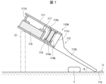
- FIG. 6 is a cross-sectional view taken along the line AA of the ethanol removal device shown in FIG. 5.
- FIG. 6 is a diagram illustrating an example of use of the ethanol removal device shown in FIG. 5.
- FIG. 2 is a schematic perspective view of a modification of the incubator shown in FIG. 1; 4 is a schematic cross-sectional view of a modification of the ethanol removal device shown in FIG. 3.
- FIG. 7 is a schematic cross-sectional view of a modification of the ethanol removal device shown in FIG. 6.
- FIG. 4 is a schematic cross-sectional view of a modification of the ethanol removal device shown in FIG. 3.
- FIG. 1 is a flowchart for explaining an ethanol removal method according to Embodiment 1 of the present disclosure.
- Some medical interventions (such as intravenous drip administration) for the affected child are performed in the incubator. Additionally, it is necessary to adsorb and remove volatile substances contained in the air within the incubator. This volatile substance is a substance used in medical intervention for patient X, such as ethanol.
- a volatile removal device is installed within the incubator to remove from the air within the incubator volatile substances used in medical interventions performed within the incubator. This can improve the safety of performing medical intervention on a patient in the incubator.
- the volatile substance removal device is installed in the incubator to remove from the air within the incubator volatile substances used in medical interventions performed within the incubator. This can improve the safety of performing medical intervention on a patient in the incubator.
- the reason why the volatile substance removal device is installed in the incubator is that problems are unlikely to occur in terms of hygiene or functionality. For example, if all or part of the volatile substance removal device is installed outside the incubator, condensation may occur due to the difference in temperature and humidity between the inside and outside of the incubator, which can easily cause problems in terms of hygiene and functionality. . For this reason, it is preferable to install the volatile substance removal device within the incubator.
- the volatile substance removal device will be referred to as an ethanol removal device.
- FIG. 1 is a schematic perspective view of the incubator 1.
- the incubator 1 includes a storage chamber 101 that accommodates the patient X, and a mounting table 102 on which the storage chamber 101 is placed. Inside the storage room 101, a bed 11 and screen sections 12 are arranged in front and behind the bed.
- the bed 11 is installed on a bed stage 13 provided on a mounting table 102.
- the bed stage 13 can move the bed 11 in the vertical direction or in the vertical and horizontal directions.
- the screen portion 12 is made of transparent resin and has a predetermined height and a predetermined width from the surface 11a of the bed 11.
- the storage room 101 is provided with two treatment openings 101a through which a doctor or nurse can administer treatment such as intravenous administration to the patient X.
- a doctor or nurse can administer treatment such as intravenous administration to the patient X.
- treatment such as intravenous administration to the patient X.
- it is necessary to disinfect the room.
- alcohol cotton is used to disinfect the area to be treated, such as the hands of patient X.
- ethanol is generated in the storage chamber 101.
- an ethanol removal device 110 is placed on the bed 11 in the storage chamber 101.
- the air in the storage chamber 101 includes first air located away from the source that emits ethanol (for example, alcohol cotton) and second air near the source that emits ethanol (for example, alcohol cotton). Therefore, the ethanol removal device 110 mainly removes ethanol from the second air near the ethanol source. Drive control of the ethanol removal device 110 is performed by operating an operating section (not shown) provided in the device.
- the incubator 1 is an incubator (so-called closed incubator) equipped with a storage chamber whose internal temperature and humidity can be adjusted to accommodate a patient.
- the incubator 1 further includes a circulation section 410, a supply section 420, and a discharge section 430.
- the circulation unit 410 circulates temperature- and humidity-controlled air into the storage chamber 101 .
- the supply unit 420 supplies air from outside the storage chamber 101 into the storage chamber 101 .
- the discharge unit 430 discharges at least a portion of the air within the storage chamber 101 to the outside of the storage chamber 101 .
- the incubator 1 is ventilated by performing natural intake and exhaust at a level at which the temperature and humidity can be maintained.
- the incubator 1 may be able to adjust not only the temperature and humidity but also the oxygen concentration.
- the direction and speed of the airflow supplied by the circulation section are taken into consideration so as not to affect the patient.
- An operation panel 102a is provided on the mounting table 102 so that a user (a doctor, a nurse, etc.) can operate the functions of the incubator 1.
- the temperature and humidity of the air in the storage chamber 101 are adjusted by the circulation section 410. Further, the ethanol removal device 110 takes in air in the storage chamber 101, removes ethanol contained in the taken air, and exhausts the air from which ethanol has been removed into the storage chamber 101 again. Thereby, ethanol can be removed from the storage chamber 101 while maintaining the temperature and humidity inside the storage chamber 101.
- Another possible method is to remove the ethanol in the air outside the incubator 1 and replace the air outside the incubator 1 with the air inside the incubator 1, but this method does not maintain the temperature and humidity inside the incubator 1. difficult.
- the ethanol removal device 110 can be freely placed and used on the bed 11. Therefore, when disinfecting patient X, by arranging the ethanol removal device 110 at a position close to the area to be disinfected, it becomes possible to effectively adsorb the ethanol generated during disinfection.
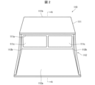
- FIG. 2 is a schematic front view of the ethanol removal device 110.
- 3 is a sectional view taken along the line AA in FIG. 2.
- FIG. 2 is a schematic front view of the ethanol removal device 110.
- the ethanol removal device 110 includes a housing 111, as shown in FIG.
- the front surface 111a of the casing 111 is provided with intake sections 111c that take in air in parallel in the longitudinal direction of the front surface 111a, and the rear surface 111b is provided with an exhaust section that exhausts the air from which ethanol has been removed within the casing 111.
- a portion 111d (FIG. 3) is provided.
- a guide portion 112 that guides air to the intake portion 111c is provided on the front surface 111a of the housing 111.
- a first removal section 114 and a suction section 115 are arranged in order from the intake section 111c toward the exhaust section 111d.
- the first removal section 114 includes crushed activated carbon 114a, and adsorbs vaporized ethanol contained in the air sucked by the suction section 115 from the first opening 114b on the suction section 111c side. The air is exhausted from the second opening 114c.
- the first removal unit 114 is a cartridge type in which crushed activated carbon 114a is housed in a cartridge that can be attached and removed from the upper side of the housing 111. This makes it easy to replace the first removal section 114. Further, the crushed activated carbon 114a is disposable. Therefore, the first removal section 114 is replaced as follows.
- the crushed activated carbon 114a housed in the first removal section 114 taken out from the casing 111 is discarded, new crushed activated carbon 114a is stored in the first removal section 114, and the first removal section 114 is removed from the casing again. Attach to 111.
- a gas sensor 117 is provided between the first removal section 114 and the suction section 115.
- This gas sensor 117 is a sensor for detecting a decrease in the ethanol adsorption ability of the first removing section 114.
- the control unit (not shown) of the ethanol removal device 110 controls when the ethanol concentration detected by the gas sensor 117 is equal to or higher than a preset value (a value for determining that the first removal unit 114 needs to be replaced). If it is determined that there is, it is determined that the ethanol adsorption capacity of the first removing section 114 is lower than a predetermined standard. That is, the control unit can notify that it is time to replace the first removal unit 114 based on the ethanol concentration detected by the gas sensor 117.
- the control unit determines whether the adsorption state of the first removal unit 114 is broken (adsorption exceeds the adsorption function and the adsorption target is leaking) based on the ethanol concentration detected by the gas sensor 117. , or whether it is sufficiently adsorbed). Therefore, gas sensor 117 functions as a breakthrough sensor.
- the gas sensor 117 is a sensor that detects a decrease in the adsorption capacity of the activated carbon in the first removal section 114, and based on the detection result of the gas sensor 117, it notifies you when it is time to replace the activated carbon in the first removal section 114. ing.
- the suction unit 115 consists of two sirocco fans, sucks air from the intake unit 111c via the first removal unit 114, and exhausts air from the exhaust unit 111d provided on the rear surface 111b of the housing 111.
- the intake air amount per minute in the suction section 115 is set to be 20 L or more, but is not limited to this. However, it is preferable that the intake air amount in the suction unit 115 is set within a range that does not disturb the environment inside the closed incubator due to the intake air amount and the exhaust air amount.
- the direction in which the air is exhausted by the exhaust section 111d is preferably a direction that does not interfere with the airflow within the incubator 1. Further, it is preferable that the air exhausted from the exhaust section 111d (air from which ethanol has been removed) does not hit the body of the patient X in the storage room 101. This is because when the air exhausted from the exhaust section 111d hits the patient X, there is a possibility that the patient's body temperature is taken away or water loss due to insensible evaporation is accelerated. Therefore, the ethanol removal device 110 is configured such that the air exhausted from the exhaust section 111d is exhausted in a direction away from the patient X in the accommodation chamber 101.
- the guide part 112 includes a placing part 112a on which at least one of the patient X who is the subject of the ethanol treatment and at least one of the ethanol generating source such as alcohol cotton can be placed.
- Either at least a part of the patient X is placed on the placement part 112a and treatment with ethanol (for example, disinfection, etc.) is performed, or alcohol cotton, etc. used for the treatment, which is the source of ethanol, is placed on the placement part 112a. If this happens, ethanol will float around a part of the patient X placed on the placement section 112a.
- the ethanol removal device 110 uses the guide section 112 to actively remove air containing ethanol floating on the placement surface (predetermined surface) on which at least a portion of the patient X of the placement section 112a is placed. Leads to 111c. Thereby, the ethanol removal device 110 can remove ethanol using the first removal section 114 and the second removal section 116 inside the housing 111.
- the ethanol removal device 110 can remove ethanol contained in the air in a short time.
- ethanol volatilized from alcoholic cotton etc. floats inside the incubator and is then discharged outside the incubator 1.
- the maximum value of the ethanol concentration within the incubator 1 cannot be suppressed.
- the ethanol concentration inside the incubator 1 is high, it takes time to discharge it outside the incubator 1, and the influence of ethanol on the patient cannot be sufficiently improved.
- the removal using the ethanol removal device 110 the ethanol volatilized from the alcohol cotton etc. is removed near the source, so the maximum concentration of ethanol in the incubator 1 can be suppressed.
- the mounting portion 112a is made of a single plate-like member (such as a resin plate), and is formed integrally with the housing 111.
- the mounting section 112a On the front surface 111a side of the housing 111, the mounting section 112a has approximately the same width in the longitudinal direction as the front surface 111a, and on the side opposite to the front surface 111a, it has a width longer than the longitudinal width of the front surface 111a. It has a substantially trapezoidal shape with a width. In this way, the width on the side facing the front surface 111a is longer than the width on the front surface 111a side. If this configuration is adopted, the ease of treatment on the mounting portion 112a will be significantly improved. Further, the placing section 112a is used not only to place a part of the patient X and perform treatment such as disinfection with alcohol cotton, but also as a temporary storage place for alcohol cotton.
- the guide portion 112 has two wall portions 112b rising upward from the periphery of the placing portion 112a.
- the wall portion 112b is formed excluding the portion facing the intake portion 111c.
- the wall portion 112b is made of the same type of material as the mounting portion 112a, and is integrally formed.
- the wall portion 112b can prevent ethanol generated after treating at least a portion of the patient X placed on the placement portion 112a from diffusing outside the placement portion 112a. This makes it possible to more actively guide air containing ethanol to the intake portion 111c.
- the treating person can place the patient Treatment (disinfection) using ethanol can be performed on at least a portion.
- the treating person is a medical person, a nurse, or the like.
- the ethanol removal device 110 can be configured so as not to impede guiding ethanol to the intake portion 111c. Thereby, treatment using ethanol for at least a part of the patient X can be performed without being obstructed by the wall portion 112b. For this reason, it becomes easier to treat the treatment target (assuming treatment by a doctor or nurse in the accommodation chamber 101 of the incubator 1), and the generated ethanol can be removed.
- the patient X can be treated with consideration to the safety within the incubator 1.
- the intake section 111c of the ethanol removal device 110 is oriented in a direction that allows the air containing vaporized ethanol to flow in an appropriate direction.
- the rotation speed of the fan is set so that the wind speed of the air sucked from the suction section 11c becomes an appropriate wind speed.
- the wall portion 112b has a shape that is highest on the front surface 111a side of the housing 111 and becomes lower as it moves away from the front surface 111a.
- the wall portion 112b By making the front surface 111a side of the housing 111 higher than the rear surface 111b in the wall portion 112b, air can be easily guided to the intake portion 111c.
- the wall portion 112b By decreasing the height of the wall portion 112b as it moves away from the front surface 111a, the wall portion 112b does not get in the way, making it easier to perform treatment on the mounting portion 112a.
- the guide section 112 In order to reliably guide the air to the intake section 111c of the housing 111, at least a portion of the guide section 112 only needs to be connected to the intake section 111c. Specifically, the mounting portion 112a of the guide portion 112 and the end portion of the wall portion 112b on the front surface 111a side may be connected to the air intake portion 111c. In this case, the air guided to the intake section 111c by the guide section 112 is difficult to leak from between the mounting section 112a of the guide section 112 and the end on the front surface 111a side of the wall section 112b and the intake section 111c, and a large amount of air is is guided to the intake section 111c. That is, by connecting at least a portion of the guide portion 112 to the intake portion 111c, air can be reliably guided to the intake portion 111c.
- the guide portion 112 that guides the air containing ethanol to the intake portion 111c has at least a portion of the hand, foot, etc. of the patient X who is the subject of treatment using ethanol placed thereon.
- the possible mounting section 112a it becomes possible to guide outside air containing ethanol, which is used when treating a treatment target with the mounting section 112a, to the intake section 111c by the guide section 112.
- the guide portion 112 be soft.
- the material applied to the guide portion 112 must, for example, have elasticity (or flexibility), be difficult to adsorb ethanol, and have no adverse effect on the body of the patient X, the gas sensor 117, and the like.
- the guide portion 112 needs to be less likely to adsorb ethanol than the first removing portion 114 .
- the ethanol removal device 110 can remove ethanol contained in the air in a short time.
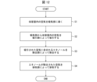
- FIG. 12 is a flowchart showing an example of the flow of the ethanol removal method according to the present embodiment.
- the ethanol removal method according to the present embodiment is installed in an incubator equipped with a storage chamber 101 whose internal temperature and humidity can be adjusted to accommodate a patient, and the ethanol removal method is applied to the patient stored in the storage chamber 101. Ethanol vaporized during medical treatment is removed from the storage chamber 101.
- step 1 (S1) the ethanol removal device 110 guides the air in the storage chamber 101 to the intake section 111c that sucks the air into the first removal section 114 (guide step).
- the first removing section 114 has a structure that realizes a removing means in this embodiment
- the intake section 111c has a structure that realizes an intake means in this embodiment.
- step 2 the ethanol removal device 110 sucks the air in the accommodation chamber 101 from the suction portion 111c using the suction portion 115 (suction step).
- the suction unit 115 has a configuration that realizes a suction means.
- step 3 the ethanol removal device 110 removes ethanol contained in the sucked air using the first removal unit 114 (removal step).
- step (S4) the ethanol removal device 110 exhausts the air from which ethanol has been removed using the exhaust section 111d (exhaust step).
- the exhaust section 111d has a configuration that realizes an exhaust means.
- the guide step for guiding the air in the accommodation chamber 101 to the intake part 111c is included, the air can be efficiently guided by the suction part 115 (suction means).
- the suction part 115 suction means
- the fan constituting the suction section 115 can be made small, so that the entire apparatus for implementing the ethanol removal method can be made small. Therefore, even if the device for realizing the ethanol removal method is used in the closed incubator 1, it will not interfere with medical treatment for the patient.
- the direction in which the air is exhausted by the exhaust section 111d may be different from the direction in which the intake section 111c (intake means) is provided.
- the intake section 111c takes in air containing ethanol, and the exhaust section 111d exhausts air from which ethanol has been removed. For this reason, when air from which ethanol has been removed is introduced into the intake portion 111c, it is not possible to efficiently intake air containing ethanol. Therefore, by setting the direction in which the air is exhausted by the exhaust part 111d to be different from the direction in which the intake part 111c is provided, the air exhausted from the exhaust part 111d (air from which ethanol has been removed) can cause the air to be exhausted by the intake part 111c. It is possible to prevent the intake of air containing ethanol from being obstructed.
- the wall portions 112b of the guide portion 112 are provided at both ends of the mounting portion 112a, but the present invention is not limited to this.
- the wall portions 112b may be provided not only at both ends of the placing portion 112a but also on the placing portion 112a. This example will be explained in Embodiment 2 below.
- FIG. 4 is a schematic front view of the ethanol removal device 210.
- the ethanol removal device 210 has the same casing 111 as the ethanol removal device 110 described in the first embodiment, and has a guide section 212 different from the ethanol removal device 110.
- the guide section 212 includes a mounting section 212a, two first walls 212b provided upwardly from both side edges of the mounting section 212a, and a wall section 212b on the mounting section 212a that is substantially parallel to the first wall section 212b. It has five second wall portions 212c provided at approximately equal intervals.
- the first wall portion 212b and the second wall portion 212c have the same shape as the wall portion 112b provided in the guide portion 112 of the ethanol removal device 110 of the first embodiment.
- the five second wall portions 212c are provided on the mounting portion 212a at approximately equal intervals, and together with the two first wall portions 212b, they form a passage (groove) for guiding air to the intake portion 111c of the housing 111.
- a passage for guiding air to the intake portion 111c of the housing 111.
- the guide section 212 is placed on or touched by at least a part of the patient's hand, foot, etc., which is the subject of treatment. Therefore, the material of the guide section 212 is It is necessary to have elasticity. Further, the guide portion 212 needs to be difficult to adsorb ethanol, and furthermore, the guide portion 212 needs to have no adverse effect on the patient X or the sensors (gas sensor 117, etc.). The guide portion 212 needs to be less likely to adsorb ethanol than the first removing portion 114 .
- the placing part 212a and the second wall part 212c that constitute the guide part 212 it is preferable that at least the second wall part 212c provided on the placing part 212a has elasticity.
- the ethanol removal device 110A has a structure in which the mounting portion 112a is removed from the guide portion 112 of the ethanol removal device 110 of the first embodiment. That is, as shown in FIG. 5, the ethanol removal device 110A has the same structure as the ethanol removal device 110 of the first embodiment, except that the structure of the guide portion 112 is different.
- a first removal section 114 and a suction section 115 are arranged in order from the intake section 111c toward the exhaust section 111d.
- the suction unit 115 consists of two sirocco fans, sucks air from the intake unit 111c via the first removal unit 114, and exhausts air from the exhaust unit 111d provided on the rear surface 111b of the housing 111.
- the intake air amount per minute in the suction section 115 is set to be 20 L or more, but is not limited to this. However, it is preferable that the intake air amount in the suction unit 115 is set within a range that does not disturb the environment inside the closed incubator due to the intake air amount and the exhaust air amount.
- the ethanol removal device 110 is configured to exhaust air in the direction away from the patient X in the accommodation chamber 101.
- the air taken in from the intake section 111c of the housing 111 is guided by the guide section 112 described above.
- the details of the guide section 112 will be explained.
- the guide portion 112 is formed to guide air containing ethanol to the intake portion 111c from a direction that is not perpendicular to the surface 11a of the bed 11, which is the mounting surface on which the alcohol cotton Y, which is the source of ethanol emission, is placed. has been done.
- the guide portion 112 is formed to guide the air containing ethanol to the suction portion 111c from a direction that is not perpendicular to the placement surface of the surface 11a of the bed 11 on which the alcoholic cotton Y is placed. Air containing ethanol emitted by the alcohol cotton Y placed on the placement surface can be guided to the intake section 111c.
- the guide part 112 In order to guide air to the intake part 111c of the housing 111, the guide part 112 must be at least partially in contact with the surface 11a of the bed 11, which is the mounting surface on which the alcoholic cotton Y that emits ethanol is placed. Preferably.
- the guide part 112 that guides the air containing ethanol to the intake part 111c comes into contact with the mounting surface of the surface 11a of the bed 11 on which the alcohol cotton Y that emits ethanol is mounted.
- the air containing ethanol emitted by the alcohol cotton Y placed on the placement surface can be more effectively guided to the intake portion 111c.
- the guide part 112 has two walls 112b surrounding a predetermined area Z on the surface of the bed 11 on which the alcoholic cotton Y that emits volatile substances is placed.
- the wall portions 112b are formed to protrude forward from both longitudinal ends of the front surface 111a of the housing 111, respectively.
- the wall portion 112b may be provided to surround the area Z, but in this embodiment, considering ease of treatment, the wall portion 112b is formed excluding the portion facing the intake portion 111c. There will be.
- the guide portion 112 has a wall portion 112b that surrounds a predetermined range Z of the surface 11a, which is the placement surface of the bed 11 on which the alcohol cotton Y, which is the generation source, is placed, so that the surface 11a
- the wall 112b can prevent the ethanol emitted from the alcohol cotton Y placed on the guide portion 112 from diffusing outside the guide portion 112.
- the ethanol removal device 110A can more actively guide air containing ethanol to the intake portion 111c.
- the wall portion 112b is formed excluding the portion facing the intake portion 111c, at least a portion of the patient X placed on the surface 11a is Treatment with ethanol can be performed. Moreover, the wall portion 112b can be configured not to obstruct the introduction of ethanol to the intake portion 111c. As a result, the treatment person can perform the treatment using ethanol on the treatment target, such as at least a part of the patient X, without being obstructed by the wall portion 112b, making it easier to treat the treatment target (assuming treatment by a doctor or nurse in the storage chamber 101 of the container 1), and the generated ethanol can be removed.
- the wall portion 112b has a shape that is highest on the front surface 111a side of the housing 111 and becomes lower as it moves away from the front surface 111a.
- the reason why the front surface 111a side of the housing 111 is made higher in the wall portion 112b is to make it easier to guide air to the intake portion 111c when the guide portion 112 is placed on the surface 11a of the bed 11.
- the reason why it becomes lower as it goes away is to make it easier to treat on the surface on which the alcohol cotton Y is placed.
- the wall portion 112b have a shape that is highest on the front surface 111a side of the housing 111 and becomes lower as it goes away from the front surface 111a, air can be introduced while the guide portion 112 is placed on the surface 11a of the bed 11. It is possible to achieve both ease of application and ease of treatment.
- the guide section 112 that guides the air containing ethanol to the intake section 111c directs the air containing ethanol to the mounting surface on which the source that emits ethanol (such as alcohol cotton Y) is placed.
- the air is formed so as to be guided to the intake portion 111c from a direction that is not perpendicular to the surface 11a of the bed 11.
- the air containing ethanol emitted by the alcohol cotton Y placed on the surface 11a of the bed 11 can be guided to the intake part 111c by the guide part 112.
- the ethanol removal device 110A can actively guide the air containing ethanol floating on the mounting surface (the surface 11a of the bed 11) on which the alcoholic cotton Y is mounted to the intake section 111c by the guide section 112. Thereby, the ethanol removal device 110A can remove ethanol contained in the air in a short time. Moreover, since the direction in which air containing ethanol is taken in by the intake part 111c is not perpendicular to the surface 11a of the bed 11 on which the alcoholic cotton Y is placed (lateral direction, diagonal direction, etc.), the alcoholic cotton Y When placed on the surface 11a of the bed 11 from above, the guide portion 112 hardly interferes with the placement. Specifically, as shown in FIG.
- the guide part 112 (in the direction facing the surface 11a of bed 11) is open. Since the doctor can place the alcohol cotton Y from above the opened guide section 112, the guide section 112 does not interfere with the doctor's operation of placing the alcohol cotton Y.
- FIG. 7 is a schematic cross-sectional view illustrating an example of use of the ethanol removal device 110A.
- the ethanol removal device 110A is basically used with the guide portion 112 and the casing 111 placed on the surface 11a of the bed 11, as shown in FIGS. 5 and 6.
- the ethanol removal device 110A brings the tip of the wall portion 112b of the guide portion 112 into contact with the surface 11a of the bed 11, and sets the tip at a predetermined angle ⁇ (0 ⁇ 90°) from the surface 11a. It may be used so that air containing ethanol generated from the alcohol cotton Y placed on the surface 11a is guided to the intake part 111c in a state of being tilted. In other words, the ethanol removal device 110A may be used so as to lead the ethanol to the intake portion 111c from a direction that is not perpendicular to the surface 11a of the bed 11.
- the wall portion 112b is made of an elastic member so that the tip of the wall portion 112b is slightly bent to increase the area in which the wall portion 112b contacts the bed 11. It's okay.
- the wall portion 112b of the ethanol removal device 110A shown in FIG. 7 may be partially cut out on the bed 11 side.
- the ethanol removal device 110A when used tilted, the ethanol removal device 110A may be supported by leaning the exhaust portion 111d side of the housing 111 against the screen portion 12.
- the screen portion 12 and the ethanol removal device 110A may be configured integrally.
- the configuration for tilting and supporting the ethanol removal device 110A is not limited to these.
- a configuration may be adopted in which a support member (not shown) having an inclined surface is installed on the surface 11a of the bed, and the ethanol removal device 110A is supported by the inclined surface of this indicator member.
- the support member and the ethanol removal device 110A may be integrally configured.
- treatment can be performed by inserting a finger or the like from the lower part of the ethanol removal device 110A (between the bed 11 and the ethanol removal device 110A). Become.
- the ethanol removal apparatuses 110, 210, and 110A of the first, second, and third embodiments drive and stop the fan in the internal suction section 115 by turning on and off the power supply.
- This power source may be a battery (primary battery, rechargeable battery, etc.), an external power source, or a combination of an external power source and a rechargeable battery.
- the power source is preferably a battery, and when the ethanol removal device is constantly installed in the incubator, the power source is preferably an external power source.
- the fan of the suction unit 115 is driven by turning on the power supply by the treating person (doctor or nurse).
- the suction force in the ethanol removal devices 110, 210, and 110A can be adjusted by the rotation speed of the fan in the suction section 115, so by changing the rotation speed of the fan according to the concentration of ethanol to be removed, it is possible to ethanol can be aspirated and removed.
- the ethanol removal devices 110, 210, and 110A of the first, second, and third embodiments each have a function of displaying the operating status (driving status).
- the function that displays the operating status includes whether the machine is running, whether it is stopped, whether the filter (activated carbon in the removal section) needs to be replaced, whether a problem has occurred, and whether the battery is low. Indicates that the information such as whether the In this case, the driving status may be displayed on the display panel or by lighting a lamp according to the driving status. Thereby, the operator can avoid forgetting to operate the ethanol removal devices 110, 210, and 110A.
- the ethanol removal devices 110, 210, and 110A can display a message prompting replacement of the filter.
- the ethanol removal devices 110, 210, and 110A of Embodiments 1, 2, and 3 are all designed to have a low height when laid down, and have a size that does not interfere with work inside the incubator 1 (2). It has become. Further, the ethanol removal devices 110, 210, and 110A preferably have a size that allows the adsorbent and the like to be easily taken in and out from the opening 101a of the incubator 1 (2) when replacing the adsorbent in the removal section. Further, the ethanol removal devices 110, 210, and 110A of the first, second, and third embodiments are preferably easy to take in and out of the opening 101a of the incubator 1 (2), and have a mass that is easy to handle (for example, 120 g). By doing so, the ethanol removal devices 110, 210, and 110A can be used in existing incubators in the ward.
- the incubator 1 is provided with air circulating in the incubator 1 by the circulation unit 410 and air being supplied from the supply unit 420 to the upper side of the bed 11 in the storage room 101. Air is supplied into the incubator 1, and air is discharged to the outside of the incubator 1 from the discharge section 430. That is, the main circulation of air in the incubator 1 shown in FIG. 1 is performed above the bed 11 in the accommodation chamber 101. Therefore, the flow of air to the patient X on the bed 11 in the accommodation room 101 may affect the temperature change inside the incubator 1. Therefore, in order to reduce the influence of temperature changes due to air flow on the patient X on the bed 11 in the accommodation room 101, for example, as in the incubator 2 shown in FIG.
- air is circulated within the incubator 2, air is supplied into the incubator 2, and air is discharged from the incubator 2.
- the direction in which air is discharged from inside the incubator 2 to the outside of the incubator 2 it is preferable to discharge the air in a direction that does not impede the circulation direction of the air within the incubator 2 (for example, in the same direction as the circulation direction).
- the same circulation section 410 and supply section 420 as in FIG. 1 are arranged below the bed 11.
- the incubator 2 shown in FIG. 8 is not provided with a device for actively discharging the air in the incubator 2 to the outside of the incubator 2 like the discharge part 430 shown in FIG. 1 of the first embodiment, and the incubator 2 The air inside is discharged to the outside of the incubator 2 through the opening 101a of the storage chamber 101, a small gap between the storage chamber 101 and the mounting table 102, and the like.
- the incubator 2 shown in FIG. 8 air whose temperature and humidity have been adjusted by a circulation unit 410 arranged at the lower part of the bed 11 is supplied from the lower part of the bed 11 to the accommodation chamber along the inner wall on the long side of the incubator 2. You will be led to the top of 101. Further, in the incubator 2, the air above the bed 11 is guided to the circulation section 410 at the bottom of the bed 11 along the inner wall on the short side of the incubator 2. In this way, in the incubator 2, air is circulated so that the patient X is less affected by temperature changes due to air flow.
- the incubator 2 shown in FIG. 8 can keep the air in the incubator 2 clean and the temperature of the air while reducing the influence of the air flow in the incubator 2 on the patient X in the accommodation room 101. ⁇ It is possible to maintain appropriate humidity.
- the first removal section 114 is of a cartridge type and is removable from the housing 111.
- the second removing section 116 is also of a cartridge type.
- the cartridge-type second removing section 116 is made removable from the top surface of the housing 111, similarly to the first removing section 114. In this way, if both the first removing section 114 and the second removing section 116 are cartridge-type, they can be easily attached and detached from the housing 111, and therefore the adsorbent in each removing section can be easily replaced.
- the direction of the air flowing through the first removal section 114 and the suction section 115 is perpendicular to the rotational axis direction of the fan, so the fan used for the suction section 115 is a sirocco fan. It is not limited to this.
- the fan used for the suction section 115 is a sirocco fan.
- an axial fan is used as the fan for the suction section 115.
- other types of fans may be used depending on the arrangement positions of the first removing section 114 and the suction section 115.
- the number of fans used in the suction section 115 is not limited to two, and may be one or three or more. Further, the type and number of fans may be appropriately determined in consideration of the required air volume, battery, and power consumption.
- the mounting part 112a of the guide part 112 is formed integrally with the housing 111. However, it is formed separately from the housing 111 and is connectable to the housing 111. It's okay.
- the mounting portion 112a is separate from the housing 111, the mounting portions 112a with different sizes and shapes can be prepared, and the ethanol removal device 110 can be provided in accordance with the installation environment. Further, the shape and size of the mounting portion 112a are not particularly limited.
- the wall portion 112b is not limited to two, but may be formed in one wall portion, as long as the wall portion 112b is formed excluding the portion facing the intake portion 111c. It may be. That is, the guide portion 112 only needs to have at least one wall portion 112b.
- the wall portion 112b is highest on the front surface 111a side of the housing 111 and becomes lower as it moves away from the front surface 111a, but the shape is not limited to this. .
- the height of the wall part 112b on the front surface 111a side of the housing 111 is the same as the height at the farthest position from the front surface 111a. Good too.
- the height of the wall section 112b is as low as possible.
- the wall portion 112b may be formed of the same type of material as the mounting portion 112a, or may be formed of a different type of material. Further, the wall portion 112b may be formed integrally with the placing portion 112a, as described in the first embodiment, or may be formed separately from the placing portion 112a. Moreover, when the wall part 112b is formed separately from the mounting part 112a, it may be detachable from the mounting part 112a. Further, the guide portion may have a structure in which the top surface of the housing 111 is slightly extended toward the mounting portion 112a (a structure in which it protrudes). By doing so, air is efficiently guided to the intake section 111c by the guide section.
- the first wall portion 212b and the second wall portion 212c of the guide portion 212 have the same shape as the wall portion 112b provided in the guide portion 112 of the first embodiment. It is not limited to the shape.
- the first wall section 212b has the same height on the front surface 111a side of the housing 111 as the height at the farthest position from the front surface 111a. You can also do this.
- the heights of the first wall part 212b and the second wall part 212c may be made as low as possible.
- the second wall portion 212c may have the same shape as the first wall portion 212b, or may have a different shape, as long as it does not get in the way during treatment. Furthermore, the lower the height of the second wall portion 212c, the easier it is to perform treatment on the placement portion 212a. Further, the number of second wall portions 212c to be provided is not limited to five, and may be less than five or more than five. Furthermore, when the first wall portion 212b and the second wall portion 212c are formed separately from the mounting portion 212a, they may be detachable from the mounting portion 212a. Further, the second wall portion 212c may be provided only in a part of the mounting portion 212a (for example, near the first wall portion 212b).
- the ethanol removal devices 110 and 210 of the first and second embodiments are usually used with the guide section 112 and the housing 111, and the guide section 212 and the housing 111 placed on the surface 11a of the bed 11.
- the tips of the guide portion 112 of the ethanol removal device 110 and the guide portion 212 of the ethanol removal device 210 are brought into contact with the surface 11a of the bed 11, and are set at a predetermined angle ⁇ (0 ⁇ 90°) from the surface 11a.
- the tilted state may be maintained to guide air containing ethanol generated from the ethanol sources (for example, alcohol cotton) placed on the placement portion 112a and the placement portion 212a to the intake portion 111c.
- the alcohol cotton Y was placed directly on the bed 11, but the invention is not limited to this, and the alcohol cotton Y is placed on a tray (not shown) and placed on the tray. may be placed on the bed 11, and the guide portion 112 may guide the air containing ethanol to the intake portion 111c.
- the wall portion 112b is not limited to two, but may be formed except for the portion facing the intake portion 111c. It may be one. That is, the guide portion 112 only needs to have at least one wall portion 112b surrounding a predetermined area Z on the surface of the bed 11 on which the alcoholic cotton Y is placed.
- the wall portion 112b is highest on the front surface 111a side of the housing 111 and becomes lower as it goes away from the front surface 111a, but the shape is not limited to this shape.
- the wall section 112b should have the same height on the front surface 111a side of the housing 111 as the height at the farthest position from the front surface 111a. It's okay.
- the height of the wall portion 112b is made as low as possible. is preferable.
- the wall portion 112b may be detachable from the housing 111.
- the guide section 112 In order to reliably guide the air to the intake section 111c of the housing 111, at least a portion of the guide section 112 only needs to be connected to the intake section 111c. Specifically, the end portion of the wall portion 112b of the guide portion 112 on the front surface 111a side may be connected to the air intake portion 111c. In this case, the air guided to the intake section 111c by the guide section 112 is difficult to leak from between the end of the wall section 112b of the guide section 112 on the front surface 111a side and the intake section 111c, and a large amount of air enters the intake section 111c. be guided.
- the top surface of the casing 111 may be formed into a guide section by extending (projecting structure) a little toward the placing section (for example, the surface 11a of the bed 11). By doing so, air can be efficiently guided to the intake portion 111c.
- the present invention is not limited to this.
- the tip of the wall portion 112b is brought into contact with the surface 11a of the bed 11, and the ethanol removal device 110 is moved from the surface 11a of the bed 11. It may be used while being tilted at a predetermined angle ⁇ (90° ⁇ 180°).
- the ethanol removal device 110A may be used so as to lead the ethanol to the intake portion 111c from a direction that is not perpendicular to the surface 11a of the bed 11.
- the first removing section 114, the suction section 115, and the second removing section 116 may be arranged in the casing 111 in this order from the intake section 111c toward the exhaust section 111d. .
- the first removal part 114 is made of sheet-like activated carbon, and quickly adsorbs most of the ethanol contained in the air taken in from the intake part 111c. Therefore, if the amount of ethanol contained in the air is small, the first removing unit 114 will adsorb all the ethanol.
- the second removal part 116 is made of pellet-shaped activated carbon, and slowly and reliably adsorbs ethanol contained in the air sucked by the suction part 115.
- the air in which ethanol has been adsorbed by the second removing section 116 is exhausted from an exhaust section 111d provided on the rear surface 111b of the housing 111.
- the first removing section 114 uses sheet-like activated carbon as an adsorbent to quickly adsorb a large amount of highly concentrated ethanol
- the second removing section 116 uses pellet-like activated carbon as an adsorbent. By using this, the ethanol that has not been completely adsorbed by the first removing section 114 is slowly adsorbed.
- the first removal section 114 quickly adsorbs a large amount of ethanol from the air taken in from the intake section 111c of the housing 111, and the second removal section 116 adsorbs all ethanol. Ethanol in the inhaled air can be sufficiently removed.
- the direction of the air flowing through the first removal section 114 and the suction section 115 is perpendicular to the rotation axis direction of the fan, so the fan used for the suction section 115 is Although a sirocco fan was used, it is not limited to this.
- a sirocco fan was used, it is not limited to this.
- an axial fan is used as the fan for the suction section 115.
- other types of fans may be used for the suction section 115 depending on the arrangement positions of the first removal section 114 and the suction section 115.
- the number of fans used in the suction section 115 is not limited to two, and may be one or three or more. Further, the type and number of fans may be appropriately determined in consideration of the required air volume, battery, and power consumption.
- the first removing section 114, the suction section 115, and the second removing section 116 may be arranged in the casing 111 in this order from the intake section 111c toward the exhaust section 111d. .
- the first removal part 114 is made of sheet-like activated carbon, and compared to the second removal part 116, it quickly adsorbs most of the ethanol contained in the air taken in from the intake part 111c.
- the first removing section 114 has higher adsorption performance than the second removing section 116 in terms of adsorption speed. Therefore, if the amount of ethanol contained in the air is small, all of the ethanol will be adsorbed in the first removal section 114.
- the first removing section 114 is made of sheet-like activated carbon, compared to the second removing section 116, the adsorption performance tends to be lower in terms of sustainability.
- the second removal section 116 is made of pellet-shaped activated carbon, and adsorbs ethanol contained in the air sucked by the suction section 115 more slowly than the first removal section 114 .
- the second removal section 116 has lower adsorption performance than the first removal section 114 in terms of adsorption speed.
- the second removal section 116 is made of pellet-shaped activated carbon, compared to the first removal section 114, the adsorption performance is less likely to deteriorate in terms of sustainability.
- the air in which ethanol has been adsorbed by the second removing section 116 is exhausted from an exhaust section 111d provided on the rear surface 111b of the housing 111.
- the first removing section 114 uses sheet-shaped activated carbon as an adsorbent to quickly adsorb a large amount of highly concentrated ethanol
- the second removing section 116 uses pellet-like activated carbon as an adsorbent. By using this, the ethanol that has not been completely adsorbed by the first removing section 114 is slowly adsorbed.
- the first removal section 114 quickly adsorbs a large amount of ethanol from the air taken in from the intake section 111c of the housing 111, and the second removal section 116 adsorbs all ethanol. Ethanol in the inhaled air can be sufficiently removed.
- ethanol may be removed by both adsorption and decomposition.
- each of the first removing section 114 and the second removing section 116 may be provided with an adsorbent and a catalyst, so that the adsorbent adsorbs ethanol and the catalyst decomposes ethanol in one removing section.
- the first removing section 114 may decompose ethanol using a catalyst
- the second removing section 116 may adsorb ethanol using an adsorbent
- the first removing section 114 may adsorb ethanol using an adsorbent
- the second removing section 114 may adsorb ethanol using an adsorbent.
- the section 116 may decompose ethanol using a catalyst.
- the adsorbent or catalyst used in the first removal section 114 and the second removal section 116 may be the same or different. .
- first removing unit 114 and the second removing unit 116 may adsorb or decompose different objects.
- the first removing section 114 may adsorb or decompose volatile substances other than ethanol
- the second removing section 116 may adsorb or decompose ethanol
- the first removing section 114 may adsorb or decompose volatile substances other than ethanol
- the second removal unit 116 may adsorb or decompose volatile substances other than ethanol.
- drive control is performed by turning the power on and off, but the invention is not limited to this.
- a concentration sensor that detects the concentration of ethanol may be installed in the storage chamber 101, and the ethanol removal devices 110 and 210 may be driven and controlled based on a detection signal from the concentration sensor. For example, when the concentration of ethanol indicated by the detection signal of the concentration sensor exceeds a predetermined concentration, the fans of the ethanol removal devices 110, 210, and 110A are started to drive, and if the concentration falls below the predetermined concentration, the ethanol removal device 110 , 210 and 110A may be stopped.
- the rotation speed of the fan in the suction section 115 is increased.
- the suction force may be increased to more actively suck the ethanol in the storage chamber 101. Thereby, ethanol can be quickly suctioned and removed.
- a gas sensor 117 is provided between the first removal section 114 and the suction section 115, and a gas sensor 117 is provided between the first removal section 114 and the suction section 115 to detect the amount of air contained in the air discharged from the first removal section 114.
- a gas sensor 117 can be connected to each removing section. It may be provided on the exhaust side of the section.
- the control unit (not shown) of the ethanol removal devices 110, 210, and 110A determines the adsorption state (breakthrough (adsorption function It is determined whether the amount of adsorption is exceeded and the adsorption target is leaking, or whether the adsorption target is sufficiently adsorbed. Further, the control unit is not limited to using the gas sensor 117 to determine the adsorption state of the first removal unit 114 and the second removal unit 116, but may use other methods (methods using sensors other than the gas sensor 117) to determine the adsorption state of the first removal unit 114 and the second removal unit 116. The adsorption state of the first removing section 114 and the second removing section 116 may be determined.
- the detection means including the gas sensor 117 may be provided inside the ethanol removal devices 110, 210, and 110A, or may be provided outside the ethanol removal devices 110, 210, and 110A; It is preferable to provide it between the first removing part 114 and the second removing part 116).
- the first removing section 114 can be operated in a state in which the adsorption amount of the first removing section 114 cannot be sufficiently exerted due to a decrease in the adsorption function of the first removing section 114, or when the adsorption amount of the second removing section 116 is It becomes possible to replace the second removing portion 116 before the amount increases and the second removing portion 116 reaches a breakthrough state.
- a detection means may be provided downstream of the second removal section 116 to detect the adsorption state of the second removal section 116.
- detection means may be provided both between the first removing section 114 and the second removing section 116 and on the downstream side of the second removing section 116, so that the adsorption state of both the first removing section 114 and the second removing section 116 is may be detected.
- the drive control of the ethanol removal devices 110 and 210 is performed by combining the detection results of a concentration sensor provided in the storage chamber 101 that detects the ethanol concentration and the detection results of the detection means that detects the adsorption state. Good too.
- the gas sensor 117 may be provided upstream of the first removal section 114. In this case, the gas sensor 117 detects the ethanol concentration contained in the air before the ethanol is adsorbed by the first removal unit 114. That is, the gas sensor 117 detects the concentration of ethanol contained in the air within the incubator 1.
- the drive of the fan of the suction unit 115 may be controlled based on the ethanol concentration detected by the gas sensor 117. For example, the rotation speed of the fan of the suction unit 115 is controlled according to the ethanol concentration detected by the gas sensor 117. In other words, if the ethanol concentration is high, the fan rotation speed is increased, and if the ethanol concentration is low, the fan rotation speed is decreased.
- the ethanol removal devices 110, 210, and 110A are also equipped with a communication unit, and are monitoring devices that monitor the ethanol concentration in the incubator by communicating information on the ethanol concentration detected by the gas sensor 117 to an external device using the communication unit. May be used for
- a first shielding member 121 extending downward from above the first opening 114b partially blocks the first opening 114b.
- a second shielding member 122 extending upward from the bottom of the second opening 114c closes a part of the second opening 114c.
- the first shielding member 121 covers about two-thirds of the upper side of the first opening 114b
- the second shielding member 122 covers about two-thirds of the lower side of the second opening 114c. In this case, as shown in FIG.
- the air that entered from the suction part 111c enters from the lower side of the first opening 114b of the first removal part 114, exits from the upper side of the second opening 114c, and directly enters the suction part 114. 115.
- the air taken into the first removal section 114 flows from the bottom to the top of the pellet-shaped activated carbon 114a, so after the air is spread over almost the entire area of the pellet-shaped activated carbon 114a, 1 removing section 114.
- the method of providing the first shielding member 121 and the second shielding member 122 is not limited to the example shown in FIG. 11.
- the first shielding member 121 may be formed from below to the top of the first opening 114b, and the second shielding member 122 may be formed from above to the bottom of the second opening 114c. Only either the member 121 or the second shielding member 122 may be provided. In this case, the air taken into the first removal section 114 flows downward from above the pellet-shaped activated carbon 114a and spreads over almost the entire area of the pellet-shaped activated carbon 114a.
- the lengths of the first shielding member 121 and the second shielding member 122 in other words, the extent to which the first opening 114b and the second opening 114c are blocked are not limited to the above-mentioned content, but depend on the suction performance of the suction part. It may be set as appropriate, taking into account factors such as air flow rate and air flow rate.
- Embodiments 1 to 3 an example has been described in which the power of the ethanol removal devices 110, 210, and 110A is turned on and off by operating the power button of the operation unit included in each device, but the present invention is not limited to this. It's not a thing.
- the ethanol removal devices 110, 210, and 110A are provided with a tilt sensor, and drive and control the fan of the suction unit 115 based on a detection signal from the tilt sensor.
- the ethanol removal devices 110, 210, and 110A are in use if the detection signal of the inclination sensor indicates that the inclination angle with respect to the ground is 0° ⁇ 5° with the main power turned on.
- the ethanol removal devices 110, 210, and 110A are in a stopped state if the detection signal of the inclination sensor indicates that the inclination angle with respect to the ground is 60° ⁇ 20° with the main power turned on. Then, the fan of the suction unit 115 is stopped to stop the ethanol adsorption operation. In other words, even if the main power is turned on, the ethanol removal devices 110, 210, and 110A control the drive of the fan of the suction unit 115 after determining whether it is in use or stopped. It is possible to prevent forgetting to start or stop the device.
- the angle at which the inclination sensor determines that the vehicle is in use and the angle at which it determines that it is at rest are not limited to the above-mentioned numerical values, and may be set as appropriate.
- the ethanol removal devices 110, 210, and 110A may be provided with a sensor (hereinafter referred to as a wind speed sensor) for detecting wind speed on the intake side.
- a wind speed sensor for detecting wind speed on the intake side.
- the control units in the ethanol removal devices 110, 210, and 110A control the drive of the motor that rotates the fan of the suction unit 115 according to the wind speed detected by the wind speed sensor. For example, if the wind speed sensor detects a wind speed within a predetermined range, the control unit controls the motor to keep the rotation speed of the fan of the suction unit 115 constant.
- the control unit controls the motor to lower the rotation speed of the fan of the suction unit 115, If it is detected that the wind speed is slow, the motor is controlled to increase the rotation speed of the fan of the suction unit 115.
- the ethanol removal devices 110, 210, and 110A can prevent the environment inside the incubator 1 (2) from being affected by excessive operation of the motor that rotates the fan of the suction unit 115. .
- the ethanol removal devices 110, 210, and 110A are equipped with wind speed sensors, thereby making it possible to constantly monitor the wind speed on the intake side. As a result, the ethanol removal devices 110, 210, and 110A can suck an appropriate amount of air into themselves.
- ethanol is used as an example of a volatile substance to be removed; however, the volatile substance to be removed is not limited to ethanol, and other volatile substances such as isopropanol may be used. .
- a closed type incubator was explained as an example of the incubator, but the volatile substance removal device of the present invention can also be used in an open type incubator that is not a closed type. It's okay.
- Volatile substance removal devices 110, 210, and 110A are installed in incubators 1 and 2 equipped with a storage chamber 101 whose internal temperature and humidity can be adjusted to accommodate a patient,
- This is a volatile substance removal device that removes vaporized volatile substances from the accommodation chamber 101 during medical treatment using volatile substances for a patient X housed in the accommodation chamber 101.
- a suction section 115 that sucks out volatile substances
- a first removal section 114 that removes volatile substances contained in the air
- an exhaust section 111d that exhausts the air from which volatile substances have been removed by the first removal section 114
- an intake section 111c The guide part 112, 212 which guides air to the air may be provided.
- volatile substances such as ethanol floating around the patient in the incubator can be sufficiently removed. Furthermore, since the guide parts 112 and 212 are provided for guiding the air in the closed incubators 1 and 2 to the suction part, the air can be efficiently guided to the suction part 115. As a result, the fan constituting the suction section 115 can be made small, so the entire device can be made small. Therefore, even if the volatile substance removal devices 110, 210, and 110A are used in the closed incubators 1 and 2, they can be made small so that they do not interfere with medical treatment for the patient X.
- the guide parts 112, 212 have mounting parts 112a, 212a on which at least one of the object to be treated using the volatile substance and at least one of the sources emitting the volatile substance used in the treatment can be placed. may have.
- the guide parts 112 and 212 are mounting parts on which at least a part of a treatment target (for example, a patient's hand or foot) for a treatment using a volatile substance or a source emitting a volatile substance used in the treatment can be placed. 112a and 212a, it becomes possible to guide air containing volatile substances generated when treating the treatment target X with the placement parts 112a and 212a to the intake part 111c by the guide parts 112 and 212.
- the guide parts 112 and 212 actively guide air containing volatile substances floating near the source of the volatile substance used in the treatment placed on the placement parts 112a and 212a to the intake part 111c. becomes possible. This makes it possible to remove volatile substances contained in the air in the closed incubators 1 and 2 in a short time.
- the guide parts 112, 212 may have at least one first wall part (wall part) 112b, 212b rising upward from the periphery of the placing part 112a, 212a. Since the guide parts 112, 212 have at least one first wall part (wall part) 112b, 212b rising upward from the periphery of the placing parts 112a, 212a, the guide parts 112, 212 can be placed on the placing parts 112a, 212a.
- the walls can prevent volatile substances generated during treatment of the treated object from diffusing outside the mounting sections 112a, 212a. This makes it possible to more actively guide air containing volatile substances to the intake portion 111c.
- the guide portions 112, 212 include at least one second wall portion (wall portion) 112b, 212c provided on the placement surface of the placement portion 112a, 212a in parallel to the first wall portion (wall portion) 112b, 212b. You can leave it there. According to the above configuration, the second wall portions (wall portions) 112b and 212c are provided on the placement surface, so that the first wall portions (wall portions) 112b and 212b and the second wall portion are provided on the placement surface. (Wall portions) 112b and 212c, the air can be guided easily to the intake portion 111c.
- the first wall portions (wall portions) 112b and 212b may be formed excluding the portion facing the intake portion 111c. Since the first wall portions (wall portions) 112b and 212b are formed excluding the portion facing the intake portion 111c, treatment is performed when the first wall portions (wall portions) 112b and 212b are placed on the placement portions 112a and 212a from a portion where no wall is formed. Subject X can be treated with a volatile substance. Further, it is possible to prevent volatile substances from being inhibited from being guided to the intake portion 111c. This makes it possible to perform treatment using volatile substances on treatment target X without being obstructed by walls, making it easier to perform treatment on treatment target X and removing volatile substances from the air. can.
- the second walls (walls) 112b, 212c may be formed of an elastic member.
- the second wall portions (wall portions) 112b and 212c provided on the placement surface have elasticity, so that the hands and feet to be treated of the patient X are placed on the placement portions 112a and 212a. It becomes less likely to be damaged even if placed.
- At least a portion of the guide parts 112, 212 may be connected to the intake part 111c. In this way, by connecting at least part of the guide parts 112, 212 to the intake part 111c, air can be reliably guided to the intake part 111c.
- a breakthrough sensor (gas sensor) 117 may be provided to detect whether the first removal section 114 is in a breakthrough state. According to the above configuration, by providing the breakthrough sensor (gas sensor) 117, it is possible to grasp the breakthrough state of the first removal section 114, and therefore it is possible to grasp the state of the first removal section 114. can.
- the first removal unit 114 may be replaceable. According to the above configuration, since the first removing section 114 is replaceable, if the first removing section 114 is in a breakthrough state, it can be replaced immediately.
- a volatile substance removal method is installed in incubators 1 and 2 equipped with a storage chamber 101 whose internal temperature and humidity can be adjusted in order to accommodate a patient X.
- This is a removal method that removes volatile substances that have vaporized during medical treatment using volatile substances for patient X housed in the hospital.
- the volatile substance removal method includes a guide step (S1), a suction step (S2), a removal step (S3), and an exhaust step (S4) described below.
- - Suction step (S2) The air inside the incubators 1 and 2 is sucked from the suction means (for example, the suction section 111c) by the suction means (for example, the suction section 115).
- - Removal step (S3) Volatile substances contained in the sucked air are removed by a removal means (for example, the first removal unit 114).
- - Exhaust step (S4) The air from which volatile substances have been removed is exhausted by an exhaust means (for example, the exhaust section 111d).
- volatile substances such as ethanol floating around the patient in the incubator can be sufficiently removed. Furthermore, since it includes a guide step for guiding the air in the closed incubators 1 and 2 to the intake part 111c, the air can be efficiently guided by the suction means. As a result, the fan constituting the suction means can be made small, so the entire device for implementing the volatile substance removal method can be made small. Therefore, even if the device for realizing the volatile substance removal method is used in the closed incubators 1 and 2, it will not interfere with medical treatment for the patient X.
- the direction in which the air is exhausted by the exhaust means may be different from the direction in which the air intake means is provided.
- the intake means takes in air containing volatile substances, and the exhaust means exhausts air from which volatile substances have been removed. Therefore, if air from which volatile substances have been removed is introduced into the intake means, air containing volatile substances cannot be efficiently taken in. Therefore, by setting the direction in which the air is exhausted by the exhaust means to be different from the direction in which the intake means is provided, the air exhausted from the exhaust means (air from which volatile substances have been removed) can reduce the volatility caused by the intake means. This allows for unobstructed intake of air containing substances.
- the volatile substance removal devices 110, 210, and 110A are volatile substance removal devices that remove volatile substances generated during medical intervention in the incubators 1 and 2, and are A suction section 115 that sucks air, removal sections 114 and 116 that remove volatile substances to be removed contained in the air, and an exhaust section that exhausts the air from which volatile substances have been removed by the removal sections 114 and 116.
- 111d and a guide section 112, 212 that guides the air to the intake section 111c, and the guide section 112, 212 guides at least a part of the treatment target using the volatile substance and the volatile substance.
- the air containing the volatile substance is formed to have a mounting part 112a, 212a on which at least one of the sources emitting the volatile substance can be placed, or the air containing the volatile substance is transferred to a mount on which the source emitting the volatile substance is placed. It is formed so as to lead to the air intake portion 111c from a direction that is not perpendicular to the placement surface.
- the guide parts 112 and 212 are arranged in the placing part 112a on which at least a part of the treatment target (for example, a patient's hand, foot, etc.) using a volatile substance (for example, ethanol) can be placed.
- a volatile substance for example, ethanol
- the guide portions 112, 212 actively guide air containing volatile substances floating near the source of the volatile substance used in the treatment placed on the placement portions 112a, 212a to the intake portion. becomes possible. This makes it possible to remove volatile substances contained in the air in a short time.
- the guide parts 112 and 212 guide the air containing volatile substances to the intake part 111c from a direction that is not perpendicular to the mounting surface on which the source of volatile substances (alcohol cotton, etc.) is mounted.
- the guide parts 112, 212 can actively guide air containing volatile substances floating on the mounting surface on which the source of volatile substances is placed to the removal parts 114, 116 via the intake part 111c. can. This makes it possible to remove volatile substances contained in the air in a short time.
- the direction in which air containing volatile substances is taken in by the intake part 111c is not perpendicular to the mounting surface on which the source that emits volatile substances is placed (lateral direction, diagonal direction, etc.), When placing the generation source on the mounting surface from above, it is not easily disturbed by the guide parts 112, 212.
- the guide portions 112, 212 are formed to have placement portions 112a, 212a on which at least one of the object to be treated using the volatile substance and at least one of the source of the volatile substance can be placed.
- the guide portions 112, 212 may include at least one wall portion 112b, 212b rising upward from the periphery of the placement portion 112a, 212a. Since the guide part has wall parts 112b and 212b that surround a predetermined range of the mounting surface on which the generation source is mounted, at least a part of the treatment target placed on the mounting parts 112a and 212a The wall can prevent volatile substances emitted from at least one of the , and the generation of volatile substances from diffusing outside the guide portions 112 and 212 . This makes it possible to more actively guide air containing volatile substances to the intake portion 111c.
- the wall portions 112b and 212b may be formed excluding the portion facing the intake portion. Since the wall portions 112b and 212b are formed excluding the portion facing the suction portion 111c, volatile property is removed from the portion where the wall is not formed to the treatment target placed on the placement portions 112a and 212a. Treatments using substances can be performed. Further, it is possible to prevent volatile substances from being inhibited from being guided to the intake portion 111c. Thereby, the treatment using the volatile substance on the treatment target can be performed without being obstructed by the wall, so that the treatment on the treatment target can be easily performed and the volatile substance can be removed.
- the guide parts 112, 212 are formed to guide the air containing the volatile substance to the intake part 111c from a direction that is not perpendicular to a mounting surface on which a source that emits the volatile substance is mounted. In this case, at least a portion of the guide portions 112, 212 may be in contact with a mounting surface on which a source emitting the volatile substance is mounted. At least a part of the guide parts 112 and 212 that guide the air containing volatile substances to the intake part 111c comes into contact with the mounting surface on which a source (such as alcohol cotton) that emits the volatile substances is mounted. Air containing volatile substances emitted from the source placed on the placement surface can be more effectively guided to the intake portion 111c.
- a source such as alcohol cotton
- the guide parts 112, 212 may have at least one wall part 112b, 212b surrounding a predetermined range of the mounting surface on which the generation source is mounted. Since the guide portions 112 and 212 have at least one wall portion 112b and 212b that surrounds a predetermined range of the placement surface on which the generation source is placed, the source placed on the placement surface can be The walls can prevent the emitted volatile substances from diffusing outside the guide portions 112, 212. This makes it possible to more actively guide air containing volatile substances to the intake section.
- the wall portions 112b and 212b may be formed excluding a portion facing the intake portion 111c. Since the wall portions 112b and 212b are formed excluding a part of the predetermined range of the mounting portion (the portion facing the intake portion 111c), the source of generation can be isolated from the portion where the wall is not formed on the mounting surface. can be placed in This makes it easier to repeat the task of placing the generation source on the mounting surface because the wall does not interfere with the placement of the generation source on the mounting surface.
Landscapes
- Health & Medical Sciences (AREA)
- Chemical & Material Sciences (AREA)
- Veterinary Medicine (AREA)
- Gynecology & Obstetrics (AREA)
- Life Sciences & Earth Sciences (AREA)
- Animal Behavior & Ethology (AREA)
- General Health & Medical Sciences (AREA)
- Public Health (AREA)
- Pediatric Medicine (AREA)
- Pregnancy & Childbirth (AREA)
- Engineering & Computer Science (AREA)
- Analytical Chemistry (AREA)
- General Chemical & Material Sciences (AREA)
- Oil, Petroleum & Natural Gas (AREA)
- Chemical Kinetics & Catalysis (AREA)
- Accommodation For Nursing Or Treatment Tables (AREA)
- Separation Of Gases By Adsorption (AREA)
Abstract
保育器内の患児付近に漂うエタノール等の揮発性物質を十分に除去できる揮発性物質除去装置を提供する。揮発性物質除去装置(110、210、110A)は、吸気部(111c)から収容室(101)内の空気を吸引する吸引部(115)と、空気に含まれる揮発性物質を除去する除去部(114、116)と、除去部(114、116)によって揮発性物質が除去された空気を排気する排気部(111d)と、吸気部(111c)に空気を導くガイド部(112、212)と、を備えている。
Description
本発明は、医学的介入において気化した揮発性物質を除去する揮発性物質除去装置および揮発性物質除去方法に関する。
保育器内では、収容されている患児に対して医療行為が行われる。例えば、保育器内で患児に対して医療行為を行う際に、消毒や医療行為実施者の手指消毒の目的等に使用されるアルコール類として、あるいは薬品の溶媒として、揮発性物質が使用され得る。例えば、消毒等に使用されるアルコール類としては、エタノールおよびイソプロパノール等が挙げられる。このような揮発性物質が保育器内で使用され、気化した場合、保育器内の患児が揮発性物質に長時間暴露されてしまう虞がある。例えば、エタノールおよびイソプロパノールは、患児の身体および生育に悪影響を与える可能性がある。それゆえ、保育器内の患児に対する医療行為においてエタノールを使用する場合には、保育器内の空気中の揮発性物質の濃度の上昇を抑える必要がある。
しかしながら、病室や病棟内等の保育器を設置している空間の揮発性物質を除去するだけでは、保育器内の患児付近に漂う揮発性物質を除去するには不十分である。
本開示は、保育器内の患児付近に漂うエタノール等の揮発性物質を十分に除去できる揮発性物質除去装置および揮発性物質除去方法を提供することを目的とする。
本開示の一側面に係る揮発性物質除去装置は、患児を収容するために内部の温度および湿度が調節可能な収容室を備えた保育器内に設置され、前記収容室内に収容された患児に対する揮発性物質による医療行為にともない気化した揮発性物質を前記収容室から除去する揮発性物質除去装置であって、吸気部から前記収容室内の空気を吸引する吸引部と、前記空気に含まれる揮発性物質を除去する除去部と、前記除去部によって揮発性物質が除去された空気を排気する排気部と、前記吸気部に前記空気を導くガイド部と、を備えている。
本開示の一側面に係る揮発性物質除去方法は、患児を収容するために内部の温度および湿度が調節可能な収容室を備えた保育器内に設置され、前記収容室内に収容された患児に対する揮発性物質による医療行為にともない気化した揮発性物質を除去する揮発性物質除去方法であって、前記収容室内の空気を、除去手段に吸引する吸気手段に導くガイドステップと、前記吸気手段から前記収容室内の空気を吸引手段によって吸引する吸引ステップと、吸引された空気に含まれる揮発性物質を前記除去手段によって除去する除去ステップと、揮発性物質が除去された空気を排気手段によって排気する排気ステップと、を含む。
〔実施形態1〕
以下、本発明の一実施形態について、詳細に説明する。以下では保育器は、後述する閉鎖型保育器を例にして説明する。
以下、本発明の一実施形態について、詳細に説明する。以下では保育器は、後述する閉鎖型保育器を例にして説明する。
患児に対する医学的介入(点滴投与等)には、保育器内で実施されるものがある。また、保育器内の空気に含まれる揮発性物質を吸着除去する必要がある。この揮発性物質は、エタノールのような患児Xに対する医学的介入において使用される物質である。
従って、保育器内には、保育器内で実施される医学的介入において使用される揮発性物質を、該保育器内の空気から除去する揮発性物質除去装置が設置されている。これにより、患児に対する医学的介入を保育器内において行うことの安全性を向上させることができる。なお、揮発性物質除去装置を保育器内に設置する理由の一例として、衛生面や機能面で問題が生じ難いことを挙げることができる。例えば、揮発性物質除去装置の全てあるいは一部を保育器外に設置した場合、保育器内と保育器外との温湿度差によって結露などが生じ、衛生面や機能面で問題が生じ易くなる。このため、揮発性物質除去装置は、保育器内に設置するのが好ましい。以下、除去対象の揮発性物質としてエタノールを例に説明するため、揮発性物質除去装置をエタノール除去装置とする。はじめに、保育器の概要を説明する。
<保育器の概要>
図1は、保育器1の概略斜視図である。保育器1は、患児Xを収容する収容室101と、収容室101を載置する載置台102とを含む。収容室101内には、ベッド11、ベッドの前後に配置された衝立部12が配置されている。ベッド11は、載置台102上に設けられたベッドステージ13に設置されている。ベッドステージ13は、ベッド11を上下方向または上下左右方向に動かすことが可能である。衝立部12は、ベッド11の表面11aから所定の高さおよび所定の幅を有する透明な樹脂で形成されている。
図1は、保育器1の概略斜視図である。保育器1は、患児Xを収容する収容室101と、収容室101を載置する載置台102とを含む。収容室101内には、ベッド11、ベッドの前後に配置された衝立部12が配置されている。ベッド11は、載置台102上に設けられたベッドステージ13に設置されている。ベッドステージ13は、ベッド11を上下方向または上下左右方向に動かすことが可能である。衝立部12は、ベッド11の表面11aから所定の高さおよび所定の幅を有する透明な樹脂で形成されている。
収容室101には、医師または看護師が患児Xに対して点滴投与等の処置を行うための処置用の開口部101aが2個設けられている。収容室101内で患児Xに対して何らかの処置をする場合には、必ず消毒する必要がある。例えば、酒精綿を用いて患児Xの手等の処置対象の部位を消毒する。収容室101内で酒精綿を使用すれば、当該収容室101内にエタノールが発生する。発生したエタノールを除去するために、収容室101内には、ベッド11上にエタノール除去装置110が配置されている。
ここで、収容室101内の空気は、エタノールを発する発生源(例えば酒精綿)から離れた位置の第1空気と、エタノールを発する発生源(例えば酒精綿)近傍の第2空気とを含む。従って、エタノール除去装置110は、主に、エタノールの発生源付近の第2空気からエタノールを除去する。エタノール除去装置110の駆動制御は、装置に設けられた操作部(図示せず)の操作によって行う。
保育器1は、患児を収容するために内部の温度および湿度が調節可能な収容室を備えた保育器(所謂、閉鎖型保育器)である。このため、保育器1は、さらに、循環部410、供給部420、排出部430を備える。循環部410は、温度および湿度が調節された空気を収容室101に循環させる。供給部420は、空気を収容室101外から収容室101内に供給する。排出部430は、収容室101内の空気の少なくとも一部を収容室101外に排出する。これにより、保育器1は、患児を収容する収容室における温湿度が維持され、温湿度が維持できるレベルで自然吸排気を行い換気されている。なお、保育器1は温湿度に加えて、酸素濃度が調整可能であってもよい。循環部で供給される空気の気流は、患児に影響を与えないようにその向きおよび速度等が考慮されている。
載置台102には、保育器1の機能などを、使用者(医師、看護師等)が操作できるように操作パネル102aが設けられている。
保育器1において収容室101内の空気は、循環部410によって温度および湿度が調整されている。また、エタノール除去装置110は、収容室101内の空気を吸気して、吸気した空気に含まれるエタノールを除去し、エタノールを除去した空気を再び収容室101内に排気する。これにより、収容室101内の温度および湿度を保ったまま、当該収容室101からエタノールを除去することができる。また、保育器1外の空気中のエタノールを除去し、保育器1外の空気と保育器1内の空気を入れ替える方法も考えられるが、当該方法では保育器1内の温度、湿度の維持が難しい。
また、エタノール除去装置110を収容室101内に配置することで、保育器1を設置するスペースとは別に、エタノール除去装置110を設置するためのスペースを確保する必要が無い。
また、エタノール除去装置110は、ベッド11上で自由に配置して使用できるようになっている。このため、患児Xに対して消毒する場合には、消毒する部位に近い位置にエタノール除去装置110を配置することで、消毒時に発生するエタノールを効果的に吸着することが可能となる。
<エタノール除去装置の概要>
図2は、エタノール除去装置110の概略正面図である。図3は、図2のAA線矢視断面図である。
図2は、エタノール除去装置110の概略正面図である。図3は、図2のAA線矢視断面図である。
エタノール除去装置110は、図2に示すように、筐体111を含む。筐体111の前面111aには、空気を取り込む吸気部111cが当該前面111aの長手方向に並列して設けられ、後面111bには、当該筐体111内でエタノールが除去された空気を排気する排気部111d(図3)が設けられている。筐体111の前面111aには、吸気部111cに空気を導くガイド部112が設けられている。
筐体111内には、図3に示すように、吸気部111c側から排気部111dに向かって順に、第1除去部114、吸引部115が配置されている。
第1除去部114は、破砕状の活性炭114aを含み、吸引部115によって吸気部111c側の第1開口部114bから吸引された空気に含まれる気化されたエタノールを吸着し、吸引部115側の第2開口部114cから排気する。第1除去部114は、筐体111の上部側から着脱可能なカートリッジ内に破砕状の活性炭114aを収容したカートリッジ型である。これにより、第1除去部114の交換が容易である。また、破砕状の活性炭114aは使い捨てである。このため、第1除去部114の交換は、以下のように行う。筐体111から取り出した第1除去部114に収容された破砕状の活性炭114aは捨てて、新しい破砕状の活性炭114aを第1除去部114に収容し、再度、第1除去部114を筐体111に取り付ける。
第1除去部114と吸引部115との間には、ガスセンサ117が設けられている。このガスセンサ117は、第1除去部114によるエタノールの吸着能力の低下検出するためのセンサである。具体的には、エタノール除去装置110の制御部(図示せず)は、ガスセンサ117によって検出されたエタノール濃度が予め設定した値(第1除去部114の交換要と判断するための値)以上であると判断すれば、第1除去部114のエタノール吸着能力が所定基準よりも低下していると判断する。つまり、制御部は、ガスセンサ117によって検出されたエタノール濃度から、第1除去部114の交換時期であることを知らせることができる。このように、制御部は、ガスセンサ117が検出したエタノール濃度から、第1除去部114の吸着状態(破過している(吸着機能を超えて吸着して、吸着対象が漏れている)状態か、あるいは十分に吸着できている状態か)を判断する。よって、ガスセンサ117は破過センサとして機能する。つまり、ガスセンサ117は、第1除去部114内の活性炭の吸着能力の低下を検出するセンサであり、ガスセンサ117の検出結果に基づき、第1除去部114内の活性炭の交換時期を知らせるようになっている。
吸引部115は、2つのシロッコファンからなり、第1除去部114を介して吸気部111cから空気を吸引し、筐体111の後面111bに設けられた排気部111dから排気される。ここで、吸引部115における1分間当たりの吸気量は20L以上とするが、これに限定されものではない。ただし、吸引部115における吸気量は、吸気量および排気量によって閉鎖保育器内の環境を乱さない範囲に設定されることが好ましい。
排気部111dによる空気の排気方向は、保育器1内の気流を邪魔しない方向であることが望ましい。また、排気部111dから排気される空気(エタノール除去済の空気)は、収容室101内の患児Xの身体に当たらないことが好ましい。なぜなら、排気部111dから排気される空気が患児Xにあたることによって、患児の体温を奪ったり、不感蒸泄による水分喪失を促進させたりする可能性があるからである。そこで、エタノール除去装置110は、排気部111dから排気される空気が、収容室101内の患児Xから遠ざかる方向に排気されるように構成されている。
筐体111の吸気部111cから吸気する空気は、上述したガイド部112によって導かれる。ガイド部112の詳細について説明する。ガイド部112は、エタノールによる処置の処置対象である患児Xの少なくとも一部、および酒精綿等のエタノールの発生源の少なくとも一方が載置可能な載置部112aを含む。
載置部112a上で患児Xの少なくとも一部を載置してエタノールによる処置(例えば、消毒等)が行われるか、載置部112a上にエタノールの発生源である、処置に用いる酒精綿等が置かれれば、載置部112aに載置された患児Xの一部の付近にエタノールが漂うことになる。しかしながら、エタノール除去装置110は、ガイド部112によって、載置部112aの患児Xの少なくとも一部が載置されている載置面(所定の面)に漂うエタノールを含む空気を積極的に吸気部111cに導く。これにより、エタノール除去装置110は、筐体111内の第1除去部114および第2除去部116によってエタノールを除去することができる。従って、エタノール除去装置110は、短時間で空気に含まれるエタノールを除去することが可能となる。保育器1外の空気と保育器1内の空気を入れ替える方法と比較した場合、入れ替える方法では酒精綿等から揮発したエタノールが保育器内を漂った後、保育器1外に排出されるので、保育器1内のエタノール濃度の最高値を抑制することができない。また保育器1内のエタノール濃度が高い状態になるので、保育器1外への排出にも時間を要してしまい、患児へのエタノールの影響を十分に改善できない。これに対して、エタノール除去装置110を用いる除去では、酒精綿等から揮発したエタノールを発生源の近くで除去するため、保育器1内のエタノール濃度の最高値を抑制することができるので、患児へのエタノールの影響を十分に改善することができる。なお、保育器1内外の空気を素早く入れ替えるために、保育器の扉などを開放することも考えられるが、温度や湿度、酸素濃度などの急激な変動が生じ、患児への負担が大きいため、このような方法を採用することはできない。
載置部112aは、一枚の板状部材(樹脂板等)からなり、筐体111と一体に形成されている。載置部112aは、筐体111の前面111a側では、当該前面111aの長手方向の幅とほぼ同じ幅を有し、前面111aに対向する側では、当該前面111aの長手方向の幅よりも長い幅を有する略台形状となっている。このように、前面111a側よりも当該前面111aに対向する側の幅が長い。この構成を採用すれば、載置部112a上での処置のし易さが格段に向上する。また、載置部112aは、患児Xの一部を載置して酒精綿による消毒等の処置を行うために使用される他、酒精綿の一時置き場としても使用され得る。
ガイド部112は、載置部112aの周縁から上方に立ち上がる2つの壁部112b・112bを有している。つまり、壁部112bは、吸気部111cに対向する部分を除いて形成されていることになる。ここで、壁部112bは、載置部112aと同一の種類の材料で、且つ一体的に形成されている。
壁部112bにより、載置部112aに載置された患児Xの少なくとも一部を処置した後に発生するエタノールが載置部112a外に拡散するのを防ぐことができる。これにより、吸気部111cにエタノールを含む空気をより積極的に導くことが可能となる。
しかも、壁部112bが、吸気部111cに対向する部分を除いて形成されていることで、処置者は、壁部112bが形成されていない箇所から載置部112aに載置された患児Xの少なくとも一部に対してエタノールを用いる処置(消毒)を行うことができる。ここで、処置者は、医療関係者、看護師等である。また、エタノール除去装置110は、エタノールを吸気部111cに案内するのを阻害しないようにすることができる。これにより、患児Xの少なくとも一部のような処置対象に対するエタノールを用いる処置を、壁部112bに邪魔されずに行うことができる。このため、処置対象への処置が行い易くなる(保育器1の収容室101内での医師や看護師による処置を想定)とともに、発生するエタノールを除去することができる。従って、保育器1内の安全性を考慮した処置を患児Xに対して行うことができる。また、患児Xに対する医療行為の邪魔にならないように、且つ、エタノールの除去率を向上させるために、エタノール除去装置110の吸気部111cは、気化されたエタノールを含む空気の風向が適切になる向きに配置される。さらに、エタノール除去装置110の吸引部115は、吸気部11cから吸引される空気の風速が適切となる風速になるようにファンの回転数が設定される。
壁部112bは、筐体111の前面111a側が最も高く、前面111aから遠ざかるにつれて低くなる形状となっている。壁部112bにおいて、筐体111の前面111a側を後面111bより高くすることにより、空気を吸気部111cに導き易くすることができる。壁部112bの高さを、前面111aから遠ざかるにつれて低くすることにより、壁部112bが邪魔にならないため、載置部112a上で処置の実施が容易となる。このように、壁部112bを、筐体111の前面111a側が最も高く、前面111aから遠ざかるにつれて低くなる形状とすることで、空気導入のし易さ、処置のし易さの両立を図ることができる。
空気を筐体111の吸気部111cに確実に導くには、ガイド部112の少なくとも一部が吸気部111cに接続されていればよい。具体的には、ガイド部112の載置部112aおよび壁部112bの前面111a側の端部が吸気部111cに接続されればよい。この場合、ガイド部112によって吸気部111cに導かれる空気は、当該ガイド部112の載置部112aおよび壁部112bの前面111a側の端部と吸気部111cとの間から漏れにくく、多くの空気が吸気部111cに導かれる。つまり、ガイド部112の少なくとも一部が、吸気部111cに接続されていることで、空気を確実に吸気部111cまで導くことができる。
上記構成のエタノール除去装置110によれば、吸気部111cにエタノールを含む空気を導くガイド部112は、エタノールを用いる処置の処置理対象である患児Xの手・足等の少なくとも一部が載置可能な載置部112aを有することで、載置部112aで処置対象の処置を行う際に用いるエタノールを含む外気を当該ガイド部112によって吸気部111cに導くことが可能となる。このように、ガイド部112には、処置対象である、患児Xの手・足等の少なくとも一部が載置される、または触れることになる。それゆえ、ガイド部112は柔らかいことが望ましい。ガイド部112に適用する材料は、例えば、弾性(または可撓性)を有し、エタノールが吸着し難く、さらに、患児Xの身体およびガスセンサ117等に悪影響を及ぼさないことが必要である。ガイド部112は、第1除去部114よりもエタノールが吸着し難いことが必要である。
しかも、載置部112aには、処置対象の少なくとも一部が載置されていることで、載置部112aに載置された処置対象の付近にエタノールが漂うことになる。従って、載置部112aの処置対象の載置面(所定の面)に漂うエタノールを含む空気は、ガイド部112によって積極的に吸気部111cに導かれる。これにより、エタノール除去装置110は、短時間で空気に含まれるエタノールを除去することが可能となる。
<エタノール除去方法>
図12は、本実施形態に係るエタノール除去方法の流れの一例を示すフローチャートである。本実施形態に係るエタノール除去方法は、患児を収容するために内部の温度および湿度が調節可能な収容室101を備えた保育器内に設置され、収容室101内に収容された患児に対するエタノールによる医療行為に伴い気化したエタノールを収容室101から除去する。
図12は、本実施形態に係るエタノール除去方法の流れの一例を示すフローチャートである。本実施形態に係るエタノール除去方法は、患児を収容するために内部の温度および湿度が調節可能な収容室101を備えた保育器内に設置され、収容室101内に収容された患児に対するエタノールによる医療行為に伴い気化したエタノールを収容室101から除去する。
ステップ1(S1)において、エタノール除去装置110は、収容室101内の空気を第1除去部114に吸引する吸気部111cに導く(ガイドステップ)。第1除去部114は、本実施形態において、除去手段を実現する構成であり、吸気部111cは、本実施形態において、吸気手段を実現する構成である。
ステップ2(S2)において、エタノール除去装置110は、吸気部111cから収容室101内の空気を吸引部115によって吸引する(吸引ステップ)。吸引部115は、本実施形態において、吸引手段を実現する構成である。
ステップ3(S3)において、エタノール除去装置110は、吸引された空気に含まれるエタノールを第1除去部114によって除去する(除去ステップ)。
ステップ(S4)において、エタノール除去装置110は、エタノールが除去された空気を排気部111dによって排気する(排気ステップ)。排気部111dは、本実施形態において、排気手段を実現する構成である。
上記構成によれば、収容室101内の空気を吸気部111cに導くためのガイドステップを含んでいるため、吸引部115(吸引手段)によって空気を効率良く導くことができる。これにより、吸引部115を構成するファンは小型で済むため、エタノール除去方法を実現するための装置全体を小型にすることができる。従って、エタノール除去方法を実現するための装置を、閉鎖型の保育器1内で使用しても、患児に対する医療行為の邪魔にならない。
また、排気ステップにおいて、排気部111d(排気手段)による空気の排気方向は、吸気部111c(吸気手段)が設けられる方向とは異なる方向であってよい。吸気部111cは、エタノールを含む空気を吸気し、排気部111dは、エタノールが除去された空気を排気する。このため、吸気部111cに、エタノールが除去された空気が導かれると、エタノールを含む空気を効率よく吸気することができない。従って、排気部111dによる空気の排気方向を、吸気部111cが設けられる方向とは異なる方向にすることで、排気部111dから排気される空気(エタノールが除去された空気)によって、吸気部111cによるエタノールを含む空気の吸気を邪魔しないようにできる。
なお、本実施形態では、ガイド部112の壁部112bは、載置部112aの両側端に設けた例について説明したが、これに限定されるものではない。例えば、壁部112bは、載置部112aの両側端だけでなく、載置部112a上にも設けてもよい。この例について、以下の実施形態2において説明する。
〔実施形態2〕
本発明の他の実施形態について、以下に説明する。なお、説明の便宜上、上記実施形態にて説明した部材と同じ機能を有する部材については、同じ符号を付記し、その説明を繰り返さない。
本発明の他の実施形態について、以下に説明する。なお、説明の便宜上、上記実施形態にて説明した部材と同じ機能を有する部材については、同じ符号を付記し、その説明を繰り返さない。
<揮発性除去装置の概要>
図4は、エタノール除去装置210の本概略正面図である。エタノール除去装置210は、前記実施形態1で説明したエタノール除去装置110と同じ筐体111を有し、エタノール除去装置110と異なるガイド部212を有している。
図4は、エタノール除去装置210の本概略正面図である。エタノール除去装置210は、前記実施形態1で説明したエタノール除去装置110と同じ筐体111を有し、エタノール除去装置110と異なるガイド部212を有している。
ガイド部212は、載置部212aと、載置部212aの両側縁から上方に立ち上がるように設けられた2つの第1壁部212bと、載置部212a上に第1壁部212bと略平行で略等間隔に設けられた5つの第2壁部212cとを有している。
第1壁部212bおよび第2壁部212cは、前記実施形態1のエタノール除去装置110のガイド部112に設けられた壁部112bと同じ形状である。
5つの第2壁部212cは、ほぼ等間隔で載置部212a上に設けられ、2つの第1壁部212bとで、筐体111の吸気部111cに空気を導くための通路(溝)を6つ形成する。このように、筐体111の吸気部111cに空気を導くための溝が6つ形成されれば、空気を吸気部111cに導き易くなり、空気に含まれる発生源からのエタノールはもれなく除去される。
ガイド部212は、前記実施形態1のガイド部112と同様に、処置対象である、患児Xの手・足等の少なくとも一部が載置または触れることになるため、ガイド部212の材料としては弾性を有することが必要である。また、ガイド部212には、エタノールが吸着し難いことも必要であり、さらにガイド部212が、患児Xやセンサ(ガスセンサ117等)に悪影響を及ぼさないことが必要である。ガイド部212は、第1除去部114よりもエタノールが吸着し難いことが必要である。
ただし、ガイド部212を構成する載置部212aと第2壁部212cのうち、少なくとも載置部212a上に設けられた第2壁部212cは弾性を有することが好ましい。
〔実施形態3〕
本発明の他の実施形態について、以下に説明する。なお、説明の便宜上、上記実施形態にて説明した部材と同じ機能を有する部材については、同じ符号を付記し、その説明を繰り返さない。
本発明の他の実施形態について、以下に説明する。なお、説明の便宜上、上記実施形態にて説明した部材と同じ機能を有する部材については、同じ符号を付記し、その説明を繰り返さない。
<エタノール除去装置の概要>
図5は、エタノール除去装置110Aの概略正面図である。図6は、図5のAA線矢視断面図である。
図5は、エタノール除去装置110Aの概略正面図である。図6は、図5のAA線矢視断面図である。
エタノール除去装置110Aは、図5および図6に示すように、前記実施形態1のエタノール除去装置110のガイド部112から載置部112aを取り除いた構造となっている。すなわち、エタノール除去装置110Aは、図5に示すように、ガイド部112の構造が異なるだけで、前記実施形態1のエタノール除去装置110と同じ構造である。
エタノール除去装置110Aの筐体111内には、図6に示すように、吸気部111c側から排気部111dに向かって順に、第1除去部114、吸引部115が配置されている。
吸引部115は、2つのシロッコファンからなり、第1除去部114を介して吸気部111cから空気を吸引し、筐体111の後面111bに設けられた排気部111dから排気される。ここで、吸引部115における1分間当たりの吸気量は20L以上とするが、これに限定されものではない。ただし、吸引部115における吸気量は、吸気量および排気量によって閉鎖保育器内の環境を乱さない範囲に設定されることが好ましい。
排気部11dから排気される空気(エタノール除去済の空気)は、収容室101内の患児Xの身体に当たらないことが好ましい。そこで、エタノール除去装置110は、収容室101内の患児Xから遠ざかる方向に空気を排気するように構成されている。
筐体111の吸気部111cから吸気する空気は、上述したガイド部112によって導かれる。ガイド部112の詳細について説明する。ガイド部112は、エタノールを含む空気を、エタノールを発する発生源である酒精綿Yを載置した載置面であるベッド11の表面11aに対して垂直でない方向から吸気部111cに導くように形成されている。
ベッド11の表面11aに酒精綿Yを載置すれば、酒精綿Yから生じるエタノールは酒精綿Yを載置している載置面に漂うことになる。しかしながら、ガイド部112は、エタノールを含む空気を、酒精綿Yを載置したベッド11の表面11aの載置面に対して垂直でない方向から吸気部111cに導くように形成されているので、載置面に載置された酒精綿Yが発するエタノールを含む空気を吸気部111cに導くことができる。
ガイド部112は、空気を筐体111の吸気部111cに導くためには、エタノールを発する酒精綿Yが載置されている載置面であるベッド11の表面11aに、少なくとも一部が接していることが好ましい。
上記のように、吸気部111cにエタノールを含む空気を導くガイド部112の少なくとも一部が、エタノールを発する酒精綿Yが載置されているベッド11の表面11aの載置面に接することで、前記載置面に載置された酒精綿Yが発するエタノールを含む空気をより効果的に吸気部111cに導くことができる。
ガイド部112は、図5に示すように、揮発性物質を発する酒精綿Yが載置されたベッド11の表面の所定の範囲Zを囲む2つの壁部112b・112bを有している。壁部112bは、それぞれ筐体111の前面111aの長手方向の両端部から前に突き出すように形成されている。壁部112bは範囲Zの周囲を囲むように設けられてもいいが、本実施形態では処置の行い易さを考慮し、壁部112bは、吸気部111cに対向する部分を除いて形成されていることになる。
これにより、ガイド部112が、発生源である酒精綿Yが載置されたベッド11の載置面である表面11aの所定の範囲Zを囲む壁部112bを有していることで、表面11aに載置された酒精綿Yから発するエタノールが壁112bにより、ガイド部112外に拡散するのを防ぐことができる。これにより、エタノール除去装置110Aは、吸気部111cにエタノールを含む空気をより積極的に導くことが可能となる。
しかも、壁部112bが、吸気部111cに対向する部分を除いて形成されていることで、壁部112bが形成されていない箇所から表面11aに載置された患児Xの少なくとも一部に対してエタノールを用いる処置を行うことができる。また、壁部112bは、エタノールを吸気部111cに案内するのを阻害しないようにすることができる。これにより、処置者は、患児Xの少なくとも一部のような処置対象に対するエタノールを用いる処置を、壁部112bに邪魔されずに行うことができるため、処置対象への処置が行い易くなる(保育器1の収容室101内での医師や看護師による処置を想定)とともに、発生するエタノールを除去することができる。
壁部112bは、筐体111の前面111a側が最も高く、前面111aから遠ざかるにつれて低くなる形状となっている。壁部112bにおいて、筐体111の前面111a側を高くするのは、ガイド部112をベッド11の表面11aに載置した状態で、空気を吸気部111cに導き易くするためであり、前面111aから遠ざかるにつれて低くするのは、酒精綿Yの載置面上で処置をし易くするためである。このように、壁部112bを、筐体111の前面111a側が最も高く、前面111aから遠ざかるにつれて低くなる形状とすることで、ガイド部112をベッド11の表面11aに載置した状態で、空気導入のし易さ、処置のし易さの両立を図ることができる。
上記構成のエタノール除去装置110Aによれば、吸気部111cにエタノールを含む空気を導くガイド部112は、エタノールを含む空気を、エタノールを発する発生源(酒精綿Y等)を載置した載置面であるベッド11の表面11aに対して垂直でない方向から吸気部111cに導くように形成されている。これにより、ベッド11の表面11aに載置された酒精綿Yが発するエタノールを含む空気をガイド部112によって吸気部111cに導くことができる。従って、エタノール除去装置110Aは、酒精綿Yが載置されている載置面(ベッド11の表面11a)に漂うエタノールを含む空気をガイド部112によって積極的に吸気部111cに導くことができる。これにより、エタノール除去装置110Aは、短時間で空気に含まれるエタノールを除去することが可能となる。しかも、エタノールを含む空気を吸気部111cによって吸気する方向は、酒精綿Yが載置されたベッド11の表面11aに対して垂直でない向き(横方向、斜め方向等)であるため、酒精綿Yをベッド11の表面11aに上から置く際に、ガイド部112によって邪魔され難い。具体的には、図6に示すように、吸気部111cによって吸気する方向が、酒精綿Yが載置されたベッド11の表面11aに対して垂直でない向き(横方向)であれば、ガイド部112の上(ベッド11の表面11aに対向する方向)は開放されている。そして、医師は、開放されたガイド部112の上から酒精綿Yを載置できるため、ガイド部112によって医師による酒精綿Yの載置動作は邪魔されない。
(使用例)
図7は、エタノール除去装置110Aの使用例を説明する概略断面図である。エタノール除去装置110Aは、基本的に図5および図6に示すように、ガイド部112および筐体111をベッド11の表面11aに載置した状態で基本的に使用する。
図7は、エタノール除去装置110Aの使用例を説明する概略断面図である。エタノール除去装置110Aは、基本的に図5および図6に示すように、ガイド部112および筐体111をベッド11の表面11aに載置した状態で基本的に使用する。
図7に示すように、エタノール除去装置110Aは、ガイド部112の壁部112bの先端をベッド11の表面11aに接触させて、当該表面11aから所定の角度θ(0≦<θ<90°)に傾けた状態で、表面11aに載置された酒精綿Yから発生するエタノールを含む空気を吸気部111cに導くように使用してもよい。つまり、エタノール除去装置110Aは、ベッド11の表面11aに対して垂直でない方向から吸気部111cに導くように使用してもよい。
また、図7に示すエタノール除去装置110Aにおいて、壁部112bは、弾性のある部材で構成することで、壁部112bの先端を少し曲げて、壁部112bがベッド11に接する面積を増やすようにしてもよい。
また、図7に示すエタノール除去装置110Aの壁部112bは、ベッド11側の一部を切り欠くようにしてもよい。
図7に示すように、エタノール除去装置110Aを傾けて使用する場合、筐体111の排気部111d側を衝立部12に立てかけることによってエタノール除去装置110Aを支持する構成であってもよい。衝立部12とエタノール除去装置110Aを一体に構成してもよい。なお、エタノール除去装置110Aを傾けて支持する構成はこれらに限定されない。例えば、傾斜面を有する支持部材(図示せず)をベッドの表面11aに設置し、この指示部材の傾斜面によってエタノール除去装置110Aが支持される構成であってもよい。支持部材とエタノール除去装置110Aを一体に構成してもよい。
さらに、図7に示すように、エタノール除去装置110Aを傾けて支持すれば、当該エタノール除去装置110Aの下部(ベッド11とエタノール除去装置110Aとの間)から手指等を入れての処置が可能となる。
(エタノール除去装置の駆動制御)
前記実施形態1,2,3のエタノール除去装置110、210、110Aは、電源のオン・オフにより内部の吸引部115内のファンの駆動および停止を行うようになっている。この電源は、電池(1次電池、充電池等)であってもよく、外部電源であってもよく、また、外部電源と充電池との組み合わせであってもよい。エタノール除去装置の使用の都度保育器内に設置する場合には、電源は電池が好ましく、エタノール除去装置を常時保育器内に設置する場合には、電源は外部電源が好ましい。通常、収容室101内で患児Xに対して処置を行う際に、処置者(医師または看護師)によって電源をオンすることで、吸引部115のファンを駆動させる。また、エタノール除去装置110、210、110Aにおける吸引力は、吸引部115内のファンの回転数によって調整することができるので、除去するエタノールの濃度に応じてファンの回転数を変えることで、適切にエタノールの吸引および除去を行うことができる。
前記実施形態1,2,3のエタノール除去装置110、210、110Aは、電源のオン・オフにより内部の吸引部115内のファンの駆動および停止を行うようになっている。この電源は、電池(1次電池、充電池等)であってもよく、外部電源であってもよく、また、外部電源と充電池との組み合わせであってもよい。エタノール除去装置の使用の都度保育器内に設置する場合には、電源は電池が好ましく、エタノール除去装置を常時保育器内に設置する場合には、電源は外部電源が好ましい。通常、収容室101内で患児Xに対して処置を行う際に、処置者(医師または看護師)によって電源をオンすることで、吸引部115のファンを駆動させる。また、エタノール除去装置110、210、110Aにおける吸引力は、吸引部115内のファンの回転数によって調整することができるので、除去するエタノールの濃度に応じてファンの回転数を変えることで、適切にエタノールの吸引および除去を行うことができる。
また、前記実施形態1,2,3のエタノール除去装置110、210、110Aは、それぞれ動作状況(駆動状況)を表示する機能を有している。駆動状況を表示する機能とは、運転中であるか否か、停止中であるか否か、フィルタ(除去部の活性炭)交換要か否か、トラブル発生しているか否か、バッテリー低下しているか否か等を明示的に表示することを示す。この場合、駆動状況は、表示パネルに表示してもよいし、駆動状況に応じたランプを点灯させることによって表示してもよい。これにより、処置者は、エタノール除去装置110、210、110Aの作動忘れを無くすことができる。また、エタノール除去装置110、210、110Aは、フィルタの交換を促す表示をすることが可能となる。
さらに、前記実施形態1,2,3のエタノール除去装置110、210、110Aは、何れも寝かせたときの高さを低く設計し、保育器1(2)内での作業の邪魔にならないサイズとなっている。さらに、エタノール除去装置110、210、110Aは、除去部内の吸着材の交換をする際に、保育器1(2)の開口部101aから吸着材等の出し入れがし易いサイズであることが好ましい。また、前記実施形態1,2,3のエタノール除去装置110、210、110Aは、保育器1(2)の開口部101aから出し入れし易く、取り扱い易い質量(例えば120g)であることが好ましい。このようにすることで、病棟内の既存の保育器内でエタノール除去装置110、210、110Aを使用可能とすることができる。
〔変形例1〕
前記実施形態1では、収容室101に処置用の開口部101aが2個設けられている例について説明したが、開口部101aの数については少なくとも2個であればよく、3個以上であってもよい。
前記実施形態1では、収容室101に処置用の開口部101aが2個設けられている例について説明したが、開口部101aの数については少なくとも2個であればよく、3個以上であってもよい。
〔変形例2〕
前記実施形態1では、エタノール除去装置110の駆動制御を、各装置に設けられた操作部の操作によって行う例について説明したが、保育器1が備える操作パネル102aの操作によって行われるようにしてもよい。
前記実施形態1では、エタノール除去装置110の駆動制御を、各装置に設けられた操作部の操作によって行う例について説明したが、保育器1が備える操作パネル102aの操作によって行われるようにしてもよい。
〔変形例3〕
前記実施形態1では、図1に示すように、保育器1は、収容室101のベッド11の上部側で、循環部410による保育器1内の空気の循環、供給部420からの保育器1内への空気の供給、排出部430からの保育器1外への空気の排出を行っている。つまり、図1に示す保育器1における主な空気の循環は、収容室101のベッド11の上部側で行われる。このため、収容室101のベッド11上の患児Xに空気の流れは、保育器1内の温度変化に影響を与える可能性がある。そこで、収容室101のベッド11上の患児Xに空気の流れによる温度変化の影響を少なくするために、例えば図8に示す保育器2のように、収容室101のベッド11の下部側で、空気の保育器2内での循環、空気の保育器2内への供給、および空気の保育器2外の排出を行うようにすることが好ましい。なお、保育器2内から保育器2外への空気の排出方向については、保育器2内の空気の循環方向を阻害しない方向(例えば循環方向と同じ方向)に排出するのが好ましい。
前記実施形態1では、図1に示すように、保育器1は、収容室101のベッド11の上部側で、循環部410による保育器1内の空気の循環、供給部420からの保育器1内への空気の供給、排出部430からの保育器1外への空気の排出を行っている。つまり、図1に示す保育器1における主な空気の循環は、収容室101のベッド11の上部側で行われる。このため、収容室101のベッド11上の患児Xに空気の流れは、保育器1内の温度変化に影響を与える可能性がある。そこで、収容室101のベッド11上の患児Xに空気の流れによる温度変化の影響を少なくするために、例えば図8に示す保育器2のように、収容室101のベッド11の下部側で、空気の保育器2内での循環、空気の保育器2内への供給、および空気の保育器2外の排出を行うようにすることが好ましい。なお、保育器2内から保育器2外への空気の排出方向については、保育器2内の空気の循環方向を阻害しない方向(例えば循環方向と同じ方向)に排出するのが好ましい。
図8に示す保育器2は、図示されていないが、図1と同じ循環部410と供給部420がベッド11の下部に配置されている。なお、図8に示す保育器2は、前記実施形態1の図1に示す排出部430のように保育器2の空気を積極的に保育器2外に排出する装置を設けず、保育器2内の空気を、収容室101の開口部101a、収容室101と載置台102との間に存在する僅かな隙間等を通して、保育器2外に排出させている。
図8に示す保育器2は、ベッド11の下部に配置された循環部410によって温度および湿度が調整された空気が、保育器2の長辺側の内壁に沿ってベッド11の下部から収容室101の上部に導かれる。また保育器2は、保育器2の短辺側の内壁に沿ってベッド11上の空気がベッド11の下部の循環部410に導かれる。このように保育器2では、患児Xに空気の流れによる温度変化の影響が少ないように空気が循環している。
従って、図8に示す保育器2は、収容室101内の患児Xに保育器2内の空気の流れの影響を少なくした状態で、保育器2内の空気を清浄に保ち、且つ空気の温度・湿度を適切に保つことが可能となる。
〔変形例4〕
前記実施形態1では、エタノール除去装置110に設けられた吸気部111cが筐体111の前面111aの長手方向に並列して設けられている例について説明したが、これに限定されるものではなく、空気を取り込むことができれば、どこに設けられてもよく、また、どのような構造であってもよい。また、前記実施形態1では、エタノール除去装置110に設けられた排気部111dが筐体111の後面111bに設けられている例について説明したが、これに限定されるものではなく、空気を排気できれば、どこに設けられてもよく、また、どのような構造であってもよい。さらに、エタノール除去装置110に設けられたガイド部112は、空気を吸気部111cに導くことができればどのような構造であってもよい。
前記実施形態1では、エタノール除去装置110に設けられた吸気部111cが筐体111の前面111aの長手方向に並列して設けられている例について説明したが、これに限定されるものではなく、空気を取り込むことができれば、どこに設けられてもよく、また、どのような構造であってもよい。また、前記実施形態1では、エタノール除去装置110に設けられた排気部111dが筐体111の後面111bに設けられている例について説明したが、これに限定されるものではなく、空気を排気できれば、どこに設けられてもよく、また、どのような構造であってもよい。さらに、エタノール除去装置110に設けられたガイド部112は、空気を吸気部111cに導くことができればどのような構造であってもよい。
〔変形例5〕
前記実施形態1では、第1除去部114をカートリッジ型で、筐体111から着脱可能である例について説明した。同様に、第2除去部116もカートリッジ型であることが好ましい。この場合、カートリッジ型の第2除去部116は、第1除去部114と同様に、筐体111の上面から着脱可能にする。このように、第1除去部114、第2除去部116の何れもカートリッジ型であれば、筐体111からの着脱も容易であるので、各除去部における吸着材の交換が容易である。
前記実施形態1では、第1除去部114をカートリッジ型で、筐体111から着脱可能である例について説明した。同様に、第2除去部116もカートリッジ型であることが好ましい。この場合、カートリッジ型の第2除去部116は、第1除去部114と同様に、筐体111の上面から着脱可能にする。このように、第1除去部114、第2除去部116の何れもカートリッジ型であれば、筐体111からの着脱も容易であるので、各除去部における吸着材の交換が容易である。
〔変形例6〕
前記実施形態1では、第1除去部114、吸引部115を流れる空気の方向がファンの回転軸方向と直交する方向であるため、吸引部に115に用いるファンはシロッコファンを用いていたが、これに限定されるものではい。例えば、第1除去部114、吸引部115を流れる空気の方向がファンの回転軸方向と同じ方向であれば、吸引部115に用いるファンとして軸流ファンを用いる。このように、第1除去部114、吸引部115の配置位置に応じて他の形式のファンを用いてもよい。また、吸引部115で用いるファンの数についても2個に限定されるものではなく、1個または3個以上であってもよい。さらに、ファンの種類や数は、必要とされる風量やバッテリー、消費電力を考慮して適宜決定すればよい。
前記実施形態1では、第1除去部114、吸引部115を流れる空気の方向がファンの回転軸方向と直交する方向であるため、吸引部に115に用いるファンはシロッコファンを用いていたが、これに限定されるものではい。例えば、第1除去部114、吸引部115を流れる空気の方向がファンの回転軸方向と同じ方向であれば、吸引部115に用いるファンとして軸流ファンを用いる。このように、第1除去部114、吸引部115の配置位置に応じて他の形式のファンを用いてもよい。また、吸引部115で用いるファンの数についても2個に限定されるものではなく、1個または3個以上であってもよい。さらに、ファンの種類や数は、必要とされる風量やバッテリー、消費電力を考慮して適宜決定すればよい。
〔変形例7〕
前記実施形態1では、ガイド部112の載置部112aは、筐体111と一体に形成された例について説明したが、筐体111と別体で形成され、筐体111と接続可能に形成されてもよい。載置部112aを筐体111と別体とする場合、大きさや形状の異なる載置部112aを用意することができ、設置環境に応じたエタノール除去装置110を提供することができる。また、載置部112aの形状および大きさに関しては特に限定されるものではない。
前記実施形態1では、ガイド部112の載置部112aは、筐体111と一体に形成された例について説明したが、筐体111と別体で形成され、筐体111と接続可能に形成されてもよい。載置部112aを筐体111と別体とする場合、大きさや形状の異なる載置部112aを用意することができ、設置環境に応じたエタノール除去装置110を提供することができる。また、載置部112aの形状および大きさに関しては特に限定されるものではない。
〔変形例8〕
前記実施形態1では、壁部112bが2つの例について説明したが、壁部112bは、吸気部111cに対向する部分を除いて形成されていればよいので、2つに限定されず、1つであってもよい。すなわち、ガイド部112は、壁部112bを少なくとも1つ有していればよい。
前記実施形態1では、壁部112bが2つの例について説明したが、壁部112bは、吸気部111cに対向する部分を除いて形成されていればよいので、2つに限定されず、1つであってもよい。すなわち、ガイド部112は、壁部112bを少なくとも1つ有していればよい。
また、前記実施形態1では、壁部112bは、筐体111の前面111a側が最も高く、前面111aから遠ざかるにつれて低くなる形状となっている例について説明したが、この形状に限定されるものではない。例えば、吸気部111cへの空気の導入のし易さを考慮した場合、壁部112bは、筐体111の前面111a側の高さと、前面111aから最も遠ざかった位置での高さとを同じにしてもよい。また、載置部112a上での処置のし易さを考慮した場合、壁部112bの高さはできるだけ低い形状にするのが好ましい。
壁部112bは、前記実施形態1で説明したように、載置部112aと同一の種類の材料で形成されてもよいし、異なる種類の材料で形成されてもよい。さらに、壁部112bは、前記実施形態1で説明したように、載置部112aと一体的に形成されていてもよいし、載置部112aと別体に形成されていてもよい。また、壁部112bは、載置部112aと別体に形成されている場合、載置部112aから着脱自在であってもよい。また、ガイド部は、筐体111の天面を載置部112a側に少し延ばす構造(突き出す構造)としてもよい。このようにすることで、空気はガイド部によって効率よく吸気部111cに導かれる。
〔変形例9〕
前記実施形態2では、ガイド部212の第1壁部212bおよび第2壁部212cの形状は、前記実施形態1のガイド部112に設けられた壁部112bと同じ形状であるとしているが、この形状に限定されるものではない。例えば、吸気部111cへの空気の導入のし易さを考慮した場合、第1壁部212bは、筐体111の前面111a側の高さと、前面111aから最も遠ざかった位置での高さとを同じにしてもよい。また、載置部212a上での処置のし易さを考慮した場合、第1壁部212bおよび第2壁部212cの高さは、できるだけ低い形状にしてもよい。
前記実施形態2では、ガイド部212の第1壁部212bおよび第2壁部212cの形状は、前記実施形態1のガイド部112に設けられた壁部112bと同じ形状であるとしているが、この形状に限定されるものではない。例えば、吸気部111cへの空気の導入のし易さを考慮した場合、第1壁部212bは、筐体111の前面111a側の高さと、前面111aから最も遠ざかった位置での高さとを同じにしてもよい。また、載置部212a上での処置のし易さを考慮した場合、第1壁部212bおよび第2壁部212cの高さは、できるだけ低い形状にしてもよい。
第2壁部212cは、第1壁部212bと同一の形状であってもよいし、異なる形状であってもよいし、処置をする際に邪魔にならない形状であればよい。さらに、第2壁部212cの高さは低いほうが載置部212a上での処置がし易い。また、第2壁部212cを設ける数は、5つに限定されるものではなく、5つより少なくてもよいし、5つよりも多くてもよい。また、第1壁部212bおよび第2壁部212cは、載置部212aと別体に形成されている場合、載置部212aから着脱自在であってよい。また、第2壁部212cは、載置部212aの一部(例えば、第1壁部212b近傍)のみに設けるようにしてもよい。このようにすることで処置対象を載置し易いスペースを載置部212aに確保しつつ、空気を吸気部111cに導き易くなり、短時間で空気に含まれるエタノールを除去することが可能となる。
〔変形例10〕
前記実施形態1、2のエタノール除去装置110および210では、通常、ガイド部112および筐体111、ガイド部212および筐体111をベッド11の表面11aに載置した状態で使用するが、これに限定されるものはでない。例えば、エタノール除去装置110のガイド部112およびエタノール除去装置210のガイド部212の先端をベッド11の表面11aに接触させて、当該表面11aから所定の角度θ(0≦<θ<90°)に傾けた状態を保持して、載置部112aおよび載置部212aに載置されたエタノールの発生源(例えば酒精綿)から発生するエタノールを含む空気を吸気部111cに導くようにしてもよい。
前記実施形態1、2のエタノール除去装置110および210では、通常、ガイド部112および筐体111、ガイド部212および筐体111をベッド11の表面11aに載置した状態で使用するが、これに限定されるものはでない。例えば、エタノール除去装置110のガイド部112およびエタノール除去装置210のガイド部212の先端をベッド11の表面11aに接触させて、当該表面11aから所定の角度θ(0≦<θ<90°)に傾けた状態を保持して、載置部112aおよび載置部212aに載置されたエタノールの発生源(例えば酒精綿)から発生するエタノールを含む空気を吸気部111cに導くようにしてもよい。
〔変形例11〕
前記実施形態3では、図6に示すように、酒精綿Yを直接ベッド11上に載置していたが、これに限定されるものではなく、トレイ(図示せず)に載せて、当該トレイをベッド11上に載置するようにして、ガイド部112によってエタノールを含む空気を吸気部111cに導くようにしてもよい。
前記実施形態3では、図6に示すように、酒精綿Yを直接ベッド11上に載置していたが、これに限定されるものではなく、トレイ(図示せず)に載せて、当該トレイをベッド11上に載置するようにして、ガイド部112によってエタノールを含む空気を吸気部111cに導くようにしてもよい。
〔変形例12〕
前記実施形態3では、壁部112bを2つ形成した例について説明したが、壁部112bは吸気部111cに対向する部分を除いて形成されていればよいので、2つに限定されず、1つであってもよい。すなわち、ガイド部112は、酒精綿Yが載置されたベッド11の表面の所定の範囲Zを囲む壁部112bを少なくとも1つ有していればよい。
前記実施形態3では、壁部112bを2つ形成した例について説明したが、壁部112bは吸気部111cに対向する部分を除いて形成されていればよいので、2つに限定されず、1つであってもよい。すなわち、ガイド部112は、酒精綿Yが載置されたベッド11の表面の所定の範囲Zを囲む壁部112bを少なくとも1つ有していればよい。
また、前記実施形態3では、壁部112bは、筐体111の前面111a側が最も高く、前面111aから遠ざかるにつれて低くなる形状となっている例について説明したが、この形状に限定されるものではなく、例えば、吸気部111cへの空気の導入のし易さを考慮した場合、壁部112bは、筐体111の前面111a側の高さと、前面111aから最も遠ざかった位置での高さとを同じにしてもよい。また、ガイド部112をベッド11の表面11aに載置した状態で、酒精綿Yの載置面上での処置のし易さを考慮した場合、壁部112bの高さをできるだけ低い形状にするのが好ましい。また、壁部112bは、筐体111から着脱自在であってもよい。
空気を筐体111の吸気部111cに確実に導くには、ガイド部112の少なくとも一部が吸気部111cに接続されていればよい。具体的には、ガイド部112の壁部112bの前面111a側の端部が吸気部111cに接続されていればよい。この場合、ガイド部112によって吸気部111cに導かれる空気は、当該ガイド部112の壁部112bの前面111a側の端部と吸気部111cとの間から漏れにくく、多くの空気が吸気部111cに導かれる。つまり、ガイド部112の少なくとも一部が、吸気部111cに接続されていることで、空気を確実に吸気部111cまで導くことができる。また、筐体111の天面を載置部(例えばベッド11の表面11a)側に少し延ばす構造(突き出す構造)としてガイド部としてもよい。このようにすることで、空気を効率よく吸気部111cに導くことができる。
〔変形例13〕
前記実施形態3では、エタノール除去装置110Aの使用例として、図7に示すように、エタノール除去装置110Aを、ガイド部112の壁部112bの先端をベッド11の表面11aに接触させて、当該表面11aから所定の角度θ(0≦<θ<90°)に傾けた状態で使用する例について説明したが、これに限定されるものではない。例えば、エタノール除去装置110Aのガイド部112には壁部112bのみが形成されているので、壁部112bの先端をベッド11の表面11aに接触させて、エタノール除去装置110をベッド11の表面11aから所定の角度θ(90°<θ≦180°)に傾けた状態で使用してもよい。つまり、エタノール除去装置110Aは、ベッド11の表面11aに対して垂直でない方向から吸気部111cに導くように使用してもよい。
前記実施形態3では、エタノール除去装置110Aの使用例として、図7に示すように、エタノール除去装置110Aを、ガイド部112の壁部112bの先端をベッド11の表面11aに接触させて、当該表面11aから所定の角度θ(0≦<θ<90°)に傾けた状態で使用する例について説明したが、これに限定されるものではない。例えば、エタノール除去装置110Aのガイド部112には壁部112bのみが形成されているので、壁部112bの先端をベッド11の表面11aに接触させて、エタノール除去装置110をベッド11の表面11aから所定の角度θ(90°<θ≦180°)に傾けた状態で使用してもよい。つまり、エタノール除去装置110Aは、ベッド11の表面11aに対して垂直でない方向から吸気部111cに導くように使用してもよい。
〔変形例14〕
前記実施形態3では、エタノール除去装置110Aが備える除去部として、第1除去部114の1つの除去部の例について説明したが、これに限定されるものではなく、除去部は2つ以上であってもよい。
前記実施形態3では、エタノール除去装置110Aが備える除去部として、第1除去部114の1つの除去部の例について説明したが、これに限定されるものではなく、除去部は2つ以上であってもよい。
例えば、筐体111内に、図10に示すように、吸気部111c側から排気部111dに向かって順に、第1除去部114、吸引部115、第2除去部116が配置されていてもよい。
第1除去部114は、シート状の活性炭からなり、吸気部111cから吸気された空気に含まれるエタノールの大部分を素早く吸着する。従って、第1除去部114は、空気に含まれるエタノールの量が少なければ、全てのエタノールを吸着することになる。
第2除去部116は、ペレット状の活性炭からなり、吸引部115によって吸引された空気に含まれるエタノールをゆっくり確実に吸着する。第2除去部116によってエタノールが吸着された空気は、筐体111の後面111bに設けられた排気部111dから排気される。
以上のように、第1除去部114では、シート状の活性炭を吸着材として用いることで、高濃度のエタノールを素早く大量に吸着し、第2除去部116では、ペレット状の活性炭を吸着材として用いることで、第1除去部114によって吸着しきれていないエタノールをゆっくり吸着する。
従って、筐体111の吸気部111cから吸気された空気は、第1除去部114によって素早く大量にエタノールが吸着され、さらに、第2除去部116によってエタノールがもれなく吸着されるので、吸気部111cから吸気された空気中のエタノールを十分に除去することができる。
〔変形例15〕
前記実施形態3では、前記実施形態1と同様に、第1除去部114、吸引部115を流れる空気の方向がファンの回転軸方向と直交する方向であるため、吸引部に115に用いるファンはシロッコファンを用いていたが、これに限定されるものではい。例えば、第1除去部114、吸引部115を流れる空気の方向がファンの回転軸方向と同じ方向であれば、吸引部115に用いるファンとして軸流ファンを用いる。このように、吸引部115に用いるファンは、第1除去部114、吸引部115の配置位置に応じて他の形式のファンを用いてもよい。また、吸引部115で用いるファンの数は2個に限定されるものではなく、1個または3個以上であってもよい。さらに、ファンの種類や数は、必要とされる風量やバッテリー、消費電力を考慮して適宜決定すればよい。
前記実施形態3では、前記実施形態1と同様に、第1除去部114、吸引部115を流れる空気の方向がファンの回転軸方向と直交する方向であるため、吸引部に115に用いるファンはシロッコファンを用いていたが、これに限定されるものではい。例えば、第1除去部114、吸引部115を流れる空気の方向がファンの回転軸方向と同じ方向であれば、吸引部115に用いるファンとして軸流ファンを用いる。このように、吸引部115に用いるファンは、第1除去部114、吸引部115の配置位置に応じて他の形式のファンを用いてもよい。また、吸引部115で用いるファンの数は2個に限定されるものではなく、1個または3個以上であってもよい。さらに、ファンの種類や数は、必要とされる風量やバッテリー、消費電力を考慮して適宜決定すればよい。
〔変形例16〕
前記実施形態1~3では、エタノール除去装置110、210および110Aが備える除去部として、第1除去部114の1つの除去部の例について説明したが、これに限定されるものではなく、除去部は2つ以上であってもよい。
前記実施形態1~3では、エタノール除去装置110、210および110Aが備える除去部として、第1除去部114の1つの除去部の例について説明したが、これに限定されるものではなく、除去部は2つ以上であってもよい。
例えば、筐体111内に、図9に示すように、吸気部111c側から排気部111dに向かって順に、第1除去部114、吸引部115、第2除去部116が配置されていてもよい。
第1除去部114は、シート状の活性炭からなり、第2除去部116と比較して、吸気部111cから吸気された空気に含まれるエタノールの大部分を素早く吸着する。換言すると、第1除去部114は、第2除去部116よりも吸着速度の観点においては吸着性能が高い。従って、空気に含まれるエタノールの量が少なければ、第1除去部114において全てのエタノールが吸着されることになる。しかしながら、第1除去部114は、シート状の活性炭からなるので、第2除去部116と比較して、持続性の観点においては吸着性能が低下しやすい。
一方、第2除去部116は、ペレット状の活性炭からなり、第1除去部114と比較して、吸引部115によって吸引された空気に含まれるエタノールをゆっくり吸着する。換言すると、第2除去部116は、第1除去部114よりも吸着速度の観点においては吸着性能が低い。しかしながら、第2除去部116は、ペレット状の活性炭からなるので、第1除去部114と比較して、持続性の観点においては吸着性能が低下し難い。第2除去部116によってエタノールが吸着された空気は、筐体111の後面111bに設けられた排気部111dから排気される。
以上のように、第1除去部114は、シート状の活性炭を吸着材として用いることで、高濃度のエタノールを素早く大量に吸着し、第2除去部116は、ペレット状の活性炭を吸着材として用いることで、第1除去部114によって吸着しきれていないエタノールをゆっくり吸着する。
従って、筐体111の吸気部111cから吸気された空気は、第1除去部114によって素早く大量にエタノールが吸着され、さらに、第2除去部116によってエタノールがもれなく吸着されるので、吸気部111cから吸気された空気中のエタノールを十分に除去することができる。
〔変形例17〕
前記実施形態1~3の第1除去部114において使用する吸着材として、ペレット状の活性炭を用いる例について説明したが、これに限定されず、シート状の活性炭、およびペレット状の活性剤等の他の吸着材を使用してもよい。
前記実施形態1~3の第1除去部114において使用する吸着材として、ペレット状の活性炭を用いる例について説明したが、これに限定されず、シート状の活性炭、およびペレット状の活性剤等の他の吸着材を使用してもよい。
また、前記変形例16では、第1除去部114において使用する吸着材として、シート状の活性炭を用い、第2除去部116において使用する吸着材としてペレット状の活性炭を用いる例について説明したが、これらに限定されず、各除去部において他の吸着材を使用してもよい。
さらに、前記変形例16では、第1除去部114と第2除去部116においてそれぞれ使用される吸着材は異なっている例について説明したが、同じであってもよい。また、エタノールを除去するために、吸着材によってエタノールを吸着する以外に、エタノールを触媒によって分解するようにしてもよい。
さらに、エタノールの吸着と分解を両方行って除去するようにしてもよい。例えば、第1除去部114と第2除去部116のそれぞれに、吸着材と触媒を備え、一つの除去部内で吸着材によるエタノールの吸着と触媒によるエタノールの分解を行うようにしてもよい。あるいは、第1除去部114が触媒によってエタノールを分解し、第2除去部116が吸着材によってエタノールを吸着してもよいし、第1除去部114が吸着材によってエタノールを吸着し、第2除去部116が触媒によってエタノールを分解してもよい。なお、第1除去部114と第2除去部116において使用される吸着材、または触媒は、第1除去部114と第2除去部116とで同じであってもよいし、異なっていてもよい。
また、第1除去部114、第2除去部116は、吸着や分解する対象が異なっていてもよい。例えば、第1除去部114は、エタノール以外の揮発性物質を吸着または分解し、第2除去部116は、エタノールを吸着または分解するようにしてもよく、あるいは、第1除去部114は、エタノールを吸着または分解し、第2除去部116は、エタノール以外の揮発性物質を吸着または分解するようにしてもよい。
〔変形例18〕
前記実施形態1~3のエタノール除去装置110、210および110Aでは、電源のオン・オフによって駆動制御を行っていたが、これに限定されるものではない。例えば、収容室101内にエタノールの濃度を検知する濃度センサを設置し、濃度センサの検知信号に基づき、エタノール除去装置110および210の駆動制御を行うようにしてもよい。例えば、濃度センサの検知信号が示すエタノールの濃度が、所定濃度以上になったときに、エタノール除去装置110、210および110Aのファンの駆動を開始させ、所定濃度よりも下がれば、エタノール除去装置110、210および110Aのファンの駆動を停止させるようにしてもよい。さらに、エタノール除去装置110、210および110Aが駆動している間、濃度センサの検知信号が示すエタノールの濃度が所定濃度よりもさらに上昇したことを示せば、吸引部115内のファンの回転数を上げるようにして、吸引力を上げて収容室101内のエタノールをより積極的に吸引するようにしてもよい。これにより、迅速にエタノールを吸引して除去することができる。
前記実施形態1~3のエタノール除去装置110、210および110Aでは、電源のオン・オフによって駆動制御を行っていたが、これに限定されるものではない。例えば、収容室101内にエタノールの濃度を検知する濃度センサを設置し、濃度センサの検知信号に基づき、エタノール除去装置110および210の駆動制御を行うようにしてもよい。例えば、濃度センサの検知信号が示すエタノールの濃度が、所定濃度以上になったときに、エタノール除去装置110、210および110Aのファンの駆動を開始させ、所定濃度よりも下がれば、エタノール除去装置110、210および110Aのファンの駆動を停止させるようにしてもよい。さらに、エタノール除去装置110、210および110Aが駆動している間、濃度センサの検知信号が示すエタノールの濃度が所定濃度よりもさらに上昇したことを示せば、吸引部115内のファンの回転数を上げるようにして、吸引力を上げて収容室101内のエタノールをより積極的に吸引するようにしてもよい。これにより、迅速にエタノールを吸引して除去することができる。
〔変形例19〕
前記実施形態1~3のエタノール除去装置110、210および110Aでは、第1除去部114と吸引部115との間には、ガスセンサ117を設け、第1除去部114から排出される空気に含まれるエタノール濃度を検出する例について説明したが、図9および図10に示すように、第1除去部114に加えて、第2除去部116を備えた場合であっても、ガスセンサ117をそれぞれの除去部の排気側に設けてもよい。
前記実施形態1~3のエタノール除去装置110、210および110Aでは、第1除去部114と吸引部115との間には、ガスセンサ117を設け、第1除去部114から排出される空気に含まれるエタノール濃度を検出する例について説明したが、図9および図10に示すように、第1除去部114に加えて、第2除去部116を備えた場合であっても、ガスセンサ117をそれぞれの除去部の排気側に設けてもよい。
この場合、エタノール除去装置110、210および110Aの制御部(図示せず)は、ガスセンサ117の検出したエタノール濃度から、第1除去部114、第2除去部116の吸着状態(破過(吸着機能を超えて吸着して、吸着対象が漏れている状態)している状態か、あるいは十分に吸着できている状態か)を判断する。また、制御部は、ガスセンサ117を用いて、第1除去部114、第2除去部116の吸着状態を判断することに限定されず、他の方法(ガスセンサ117以外のセンサを用いる方法)によって第1除去部114、第2除去部116の吸着状態を判断してもよい。
ガスセンサ117を含む検知手段は、エタノール除去装置110、210および110A内に設けてもよく、エタノール除去装置110、210および110A外に設けてもよいが、例えば、第1除去部114の下流側(第1除去部114と第2除去部116の間)に設けることが好ましい。このようにすることで、第1除去部114は、第1除去部114の吸着機能の低下にともない、第1除去部114の吸着量が十分発揮できない状態や、第2除去部116の吸着量が増大し第2除去部116が破過する状態となる前に交換することが可能となる。また、第2除去部116の下流側に検知手段を設け、第2除去部116の吸着状態を検知するようにしてもよい。あるいは、第1除去部114と第2除去部116との間と、第2除去部116の下流側の両方に検知手段を設け、第1除去部114と第2除去部116の両方の吸着状態を検知するようにしてもよい。
また、収容室101内に設けたエタノール濃度を検知する濃度センサの検知結果と、前記吸着状態を検知する検知手段の検知結果とを組み合わせてエタノール除去装置110および210の駆動制御を行うようにしてもよい。
さらに、ガスセンサ117を、第1除去部114の上流側に設けてもよい。この場合、ガスセンサ117は、第1除去部114によってエタノールが吸着される前の空気に含まれるエタノール濃度を検知する。すなわちガスセンサ117は、保育器1内の空気に含まれるエタノールの濃度を検知する。ガスセンサ117が検知したエタノール濃度から吸引部115のファンの駆動制御を行うようにしてもよい。例えば、ガスセンサ117が検知したエタノール濃度に応じて、吸引部115のファンの回転数を制御する。つまり、エタノール濃度が高ければ、ファンの回転数を上げ、エタノール濃度が低ければ、ファンの回転数を下げるようにする。
また、エタノール除去装置110、210および110Aは、通信部を備え、ガスセンサ117が検知したエタノール濃度の情報を通信部を使用して外部機器に通信し、保育器内のエタノール濃度をモニタリングするモニタリング装置に使用してもよい。
〔変形例20〕
本変形例では、図11に示すように、第1開口部114bの上から下に向かって延設された第1遮蔽部材121が、第1開口部114bの一部を塞ぐようになっている。また、第2開口部114cの下から上に向かって延設された第2遮蔽部材122が、第2開口部114cの一部を塞ぐようになっている。第1遮蔽部材121は、第1開口部114bの上側3分の2程度塞ぎ、第2遮蔽部材122は、第2開口部114cの下側3分の2程度塞いでいる。この場合、図11に示すように、吸気部111cから入った空気は、第1除去部114の第1開口部114bの下側から入り、第2開口部114cの上側から出て、そのまま吸引部115によって吸引される。つまり、第1除去部114内に取り込まれた空気は、ペレット状の活性炭114aの下から上に向かって流れるようになるため、ペレット状の活性炭114aのほぼ全域に空気を行き渡らせた後、第1除去部114から排気される。なお、第1遮蔽部材121および第2遮蔽部材122の設け方は、図11に示す例に限定されない。例えば、第1遮蔽部材121を第1開口部114bの下から上に向かって形成し、第2遮蔽部材122を第2開口部114cの上から下に向かって形成してもよく、第1遮蔽部材121および第2遮蔽部材122のどちらかのみが設けられるようにしてもよい。この場合、第1除去部114内に取り込まれた空気は、ペレット状の活性炭114aの上から下に向かって流れ、ペレット状の活性炭114aのほぼ全域に行き渡る。なお、第1遮蔽部材121および第2遮蔽部材122の長さ、換言すると第1開口部114bおよび第2開口部114cをどの程度塞ぐのかは、上述した内容に限定されず、吸着部の吸着性能や空気の流量などを考慮して適宜設定すればよい。
本変形例では、図11に示すように、第1開口部114bの上から下に向かって延設された第1遮蔽部材121が、第1開口部114bの一部を塞ぐようになっている。また、第2開口部114cの下から上に向かって延設された第2遮蔽部材122が、第2開口部114cの一部を塞ぐようになっている。第1遮蔽部材121は、第1開口部114bの上側3分の2程度塞ぎ、第2遮蔽部材122は、第2開口部114cの下側3分の2程度塞いでいる。この場合、図11に示すように、吸気部111cから入った空気は、第1除去部114の第1開口部114bの下側から入り、第2開口部114cの上側から出て、そのまま吸引部115によって吸引される。つまり、第1除去部114内に取り込まれた空気は、ペレット状の活性炭114aの下から上に向かって流れるようになるため、ペレット状の活性炭114aのほぼ全域に空気を行き渡らせた後、第1除去部114から排気される。なお、第1遮蔽部材121および第2遮蔽部材122の設け方は、図11に示す例に限定されない。例えば、第1遮蔽部材121を第1開口部114bの下から上に向かって形成し、第2遮蔽部材122を第2開口部114cの上から下に向かって形成してもよく、第1遮蔽部材121および第2遮蔽部材122のどちらかのみが設けられるようにしてもよい。この場合、第1除去部114内に取り込まれた空気は、ペレット状の活性炭114aの上から下に向かって流れ、ペレット状の活性炭114aのほぼ全域に行き渡る。なお、第1遮蔽部材121および第2遮蔽部材122の長さ、換言すると第1開口部114bおよび第2開口部114cをどの程度塞ぐのかは、上述した内容に限定されず、吸着部の吸着性能や空気の流量などを考慮して適宜設定すればよい。
〔変形例21〕
前記実施形態1~3では、エタノール除去装置110、210および110Aの電源のオン・オフは、各装置が備える操作部の電源ボタンを操作することで行う例について説明したが、これに限定されるものではない。例えば、エタノール除去装置110、210および110Aは、傾斜センサが設けられ、傾斜センサによる検知信号に基づき吸引部115のファンの駆動制御することが考えられる。この場合、エタノール除去装置110、210および110Aは、主電源をオンにした状態で、傾斜センサの検知信号が地面に対する傾斜角度が0°±5°であることを示していれば、使用状態であると判断し、吸引部115のファンを駆動させてエタノールの吸着動作を実行する。一方、エタノール除去装置110、210および110Aは、主電源をオンにした状態で、傾斜センサの検知信号が地面に対する傾斜角度が60°±20°であることを示していれば、停止状態であると判断し、吸引部115のファンを停止させてエタノールの吸着動作を停止する。つまり、エタノール除去装置110、210および110Aは、主電源がオンされていても、使用状態か停止状態かを把握してから、吸引部115のファンの駆動を制御するようになっているので、装置の作動忘れおよび停止忘れを防止することができる。なお、傾斜センサによって、使用状態であると判断するための角度、および停止状態であると判断するための角度は、上述した数値に限定されず、適宜設定すればよい。
前記実施形態1~3では、エタノール除去装置110、210および110Aの電源のオン・オフは、各装置が備える操作部の電源ボタンを操作することで行う例について説明したが、これに限定されるものではない。例えば、エタノール除去装置110、210および110Aは、傾斜センサが設けられ、傾斜センサによる検知信号に基づき吸引部115のファンの駆動制御することが考えられる。この場合、エタノール除去装置110、210および110Aは、主電源をオンにした状態で、傾斜センサの検知信号が地面に対する傾斜角度が0°±5°であることを示していれば、使用状態であると判断し、吸引部115のファンを駆動させてエタノールの吸着動作を実行する。一方、エタノール除去装置110、210および110Aは、主電源をオンにした状態で、傾斜センサの検知信号が地面に対する傾斜角度が60°±20°であることを示していれば、停止状態であると判断し、吸引部115のファンを停止させてエタノールの吸着動作を停止する。つまり、エタノール除去装置110、210および110Aは、主電源がオンされていても、使用状態か停止状態かを把握してから、吸引部115のファンの駆動を制御するようになっているので、装置の作動忘れおよび停止忘れを防止することができる。なお、傾斜センサによって、使用状態であると判断するための角度、および停止状態であると判断するための角度は、上述した数値に限定されず、適宜設定すればよい。
〔変形例22〕
前記実施形態1~3では、エタノール除去装置110、210および110Aは、吸気側に風速を検出するセンサ(以下、風速センサと称する)を設けてもよい。この場合、エタノール除去装置110、210および110Aにおける制御部は、風速センサによって検出された風速に応じて、吸引部115のファンを回転させるモータの駆動を制御する。制御部は、例えば、風速センサが所定範囲内の風速を検知すれば、吸引部115のファンの回転数を一定に保つようにモータを制御する。制御部は、例えば、風速センサが所定範囲を超えて一定の風速よりも速い風速であると検知すれば、吸引部115のファンの回転数を下げるようにモータを制御し、一定の風速よりも遅い風速であると検知すれば、吸引部115のファンの回転数を上げるようにモータを制御する。これにより、エタノール除去装置110、210および110Aは、特に、吸引部115のファンを回転させるモータが過剰に作動することで、保育器1(2)内の環境に影響することを防ぐことができる。このように、エタノール除去装置110、210および110Aは、風速センサを備えることで、吸気側の風速を常に監視することが可能となる。この結果、エタノール除去装置110、210および110Aは、自身に対して、適量の空気を吸引させることが可能となる。
前記実施形態1~3では、エタノール除去装置110、210および110Aは、吸気側に風速を検出するセンサ(以下、風速センサと称する)を設けてもよい。この場合、エタノール除去装置110、210および110Aにおける制御部は、風速センサによって検出された風速に応じて、吸引部115のファンを回転させるモータの駆動を制御する。制御部は、例えば、風速センサが所定範囲内の風速を検知すれば、吸引部115のファンの回転数を一定に保つようにモータを制御する。制御部は、例えば、風速センサが所定範囲を超えて一定の風速よりも速い風速であると検知すれば、吸引部115のファンの回転数を下げるようにモータを制御し、一定の風速よりも遅い風速であると検知すれば、吸引部115のファンの回転数を上げるようにモータを制御する。これにより、エタノール除去装置110、210および110Aは、特に、吸引部115のファンを回転させるモータが過剰に作動することで、保育器1(2)内の環境に影響することを防ぐことができる。このように、エタノール除去装置110、210および110Aは、風速センサを備えることで、吸気側の風速を常に監視することが可能となる。この結果、エタノール除去装置110、210および110Aは、自身に対して、適量の空気を吸引させることが可能となる。
なお、前記各実施形態および各変形例では、除去対象の揮発性物質としてエタノールを例に説明したが、エタノールに限定されるものではなく、例えばイソプロパノール等の他の揮発性物質であってもよい。
また、前記各実施形態および各変形例では、保育器として閉鎖型の保育器を例に説明したが、閉鎖型でない、開放型の保育器においても、本発明の揮発性物質除去装置を使用してもよい。
本開示の一側面に係る揮発性物質除去装置110、210および110Aは、患児を収容するために内部の温度および湿度が調節可能な収容室101を備えた保育器1、2内に設置され、収容室101内に収容された患児Xに対する揮発性物質による医療行為にともない気化した揮発性物質を収容室101から除去する揮発性物質除去装置であって、吸気部111cから収容室101内の空気を吸引する吸引部115と、空気に含まれる揮発性物質を除去する第1除去部114と、第1除去部114によって揮発性物質が除去された空気を排気する排気部111dと、吸気部111cに空気を導くガイド部112、212と、を備えていてもよい。
上記構成によれば、保育器内の患児付近に漂うエタノール等の揮発性物質を十分に除去することができる。さらに、閉鎖型保育器1、2内の空気を吸気部に導くためのガイド部112、212を備えているため、吸引部115に空気を効率良く導くことができる。これにより、吸引部115を構成するファンは小型で済むため、装置全体を小型にすることができる。従って、揮発性物質除去装置110、210および110Aを、閉鎖型保育器1、2内で使用しても、患児Xに対する医療行為の邪魔にならないように小型にできる。
ガイド部112、212は、前記揮発性物質を用いる処置の処置対象の少なくとも一部、および前記処置に使用した揮発性物質を発する発生源の少なくとも一方が載置可能な載置部112a、212aを有していてもよい。ガイド部112、212は、揮発性物質を用いる処置の処置対象(例えば、患児の手・足等)の少なくとも一部または処置に使用した揮発性物質を発する発生源が載置可能な載置部112a、212aを有することで、載置部112a、212aで処置対象Xを処置する際に発生する揮発性物質を含む空気をガイド部112、212によって吸気部111cに導くことが可能となる。また、載置部112a、212aに載置された前記処置に使用した揮発性物質を発する発生源の付近に漂う揮発性物質を含む空気をガイド部112、212によって積極的に吸気部111cに導くことが可能となる。これにより、短時間で閉鎖型保育器1、2内の空気に含まれる揮発性物質を除去することが可能となる。
ガイド部112、212は、載置部112a、212aの周縁から上方に立ち上がる第1壁部(壁部)112b、212bを少なくとも1つ有していてもよい。ガイド部112、212が、載置部112a、212aの周縁から上方に立ち上がる第1壁部(壁部)112b、212bを少なくとも1つ有していることで、載置部112a、212aに載置された処置対象を処置する際に発生する揮発性物質が壁により、載置部112a、212a外に拡散するのを防ぐことができる。これにより、吸気部111cに揮発性物質を含む空気をより積極的に導くことが可能となる。
ガイド部112、212は、載置部112a、212aの載置面に、第1壁部(壁部)112b、212bに並列に第2壁部(壁部)112b、212cが少なくとも1つ設けられていてもよい。上記構成によれば、載置面に第2壁部(壁部)112b、212cが設けられていることで、載置面上において第1壁部(壁部)112b、212bと第2壁部(壁部)112b、212cとの間に空気を沿わせることができるので、空気を吸気部111cに導き易くできる。
第1壁部(壁部)112b、212bは、吸気部111cに対向する部分を除いて形成されていてもよい。第1壁部(壁部)112b、212bが、吸気部111cに対向する部分を除いて形成されていることで、壁が形成されていない箇所から載置部112a、212aに載置された処置対象Xに対して揮発性物質を用いる処置を行うことができる。また、揮発性物質を吸気部111cに案内するのを阻害しないようにすることができる。これにより、処置対象Xに対する揮発性物質を用いる処置を、壁に邪魔されずに行うことができるため、処置対象Xへの処置が行い易くなるとともに、空気中の揮発性物質を除去することができる。
第1壁部(壁部)112b、212bおよび第2壁部(壁部)112b、212cのうち、少なくとも第2壁部(壁部)112b、212cは弾性を有する部材で形成されていてもよい。上記構成によれば、載置面に設けられた第2壁部(壁部)112b、212cが弾性を有することで、載置部112a、212aに患児Xの処置対象となる手や足が載置されても傷つき難くなる。
ガイド部112、212の少なくとも一部は、吸気部111cに接続されていてもよい。このように、ガイド部112、212の少なくとも一部が、吸気部111cに接続されていることで、空気を確実に吸気部111cまで導くことができる。
第1除去部114が破過状態であるか否かを検知する破過センサ(ガスセンサ)117が設けられていてもよい。上記構成によれば、破過センサ(ガスセンサ)117が設けられていることで、第1除去部114の破過状態を把握することができるため、第1除去部114の状態を把握することができる。
第1除去部114は、交換可能であってもよい。上記構成によれば、第1除去部114が交換可能であるため、第1除去部114が破過状態であれば、直ぐに交換することができる。
本開示の一側面に係る揮発性物質除去方法は、患児Xを収容するために内部の温度および湿度が調節可能な収容室101を備えた保育器1、2内に設置され、収容室101内に収容された患児Xに対する揮発性物質による医療行為にともない気化した揮発性物質を除去する除去方法である。揮発性物質除去方法は、以下に記すガイドステップ(S1)と、吸引ステップ(S2)と、除去ステップ(S3)と、排気ステップ(S4)と、を含む。・ガイドステップ(S1):収容室101内の空気を、除去手段(例えば、第1除去部114)に吸引する、吸気手段(例えば、吸気部111c)に導く。・吸引ステップ(S2):吸気手段(例えば、吸気部111c)から保育器1、2内の空気を吸引手段(例えば、吸引部115)によって吸引する。・除去ステップ(S3):吸引された空気に含まれる揮発性物質を除去手段(例えば、第1除去部114)によって除去する。・排気ステップ(S4):揮発性物質が除去された空気を排気手段(例えば、排気部111d)によって排気する。
上記構成によれば、保育器内の患児付近に漂うエタノール等の揮発性物質を十分に除去することができる。さらに、閉鎖型保育器1、2内の空気を吸気部111cに導くためのガイドステップを含んでいるため、吸引手段によって空気を効率良く導くことができる。これにより、吸引手段を構成するファンは小型で済むため、揮発性物質除去方法を実現するための装置全体を小型にすることができる。従って、揮発性物質除去方法を実現するための装置を、閉鎖型保育器1、2内で使用しても、患児Xに対する医療行為の邪魔にならない。
前記排気手段による空気の排気方向は、前記吸気手段が設けられる方向とは異なる方向であってもよい。吸気手段は、揮発性物質を含む空気を吸気し、排気手段は、揮発性物質が除去された空気を排気する。このため、吸気手段に、揮発性物質が除去された空気が導かれると、揮発性物質を含む空気を効率よく吸気することができない。従って、排気手段による空気の排気方向を、吸気手段が設けられる方向とは異なる方向にすることで、排気手段から排気される空気(揮発性物質が除去された空気)によって、吸気手段による揮発性物質を含む空気の吸気を邪魔しないようにできる。
本開示の一側面に係る揮発性物質除去装置110、210、110Aは、保育器1、2で医学的介入において発生する揮発性物質を除去する揮発性物質除去装置であって、吸気部111cから空気を吸引する吸引部115と、前記空気に含まれる除去対象の揮発性物質を除去する除去部114、116と、前記除去部114、116によって揮発性物質が除去された空気を排気する排気部111dと、前記吸気部111cに前記空気を導くガイド部112、212と、を備え、前記ガイド部112、212は、前記揮発性物質を用いる処置の処置対象の少なくとも一部、および前記揮発性物質の発生源の少なくとも一方が載置可能な載置部112a、212aを有するように形成されている、または、前記揮発性物質を含む空気を、当該揮発性物質を発する発生源を載置した載置面に対して垂直でない方向から前記吸気部111cに導くように形成されている。
上記構成によれば、ガイド部112、212が、揮発性物質(例えば、エタノール)を用いる処置の処置対象(例えば、患児の手・足等)の少なくとも一部が載置可能な載置部112a、212aを有することで、載置部112a、212aで処置対象を処置する際に発生する揮発性物質を含む空気を当該ガイド部112、212によって吸気部111cに導くことが可能となる。また、載置部112a、212aに載置された前記処置に使用した揮発性物質を発する発生源の付近に漂う揮発性物質を含む空気をガイド部112、212によって積極的に吸気部に導くことが可能となる。これにより、短時間で空気に含まれる揮発性物質を除去することが可能となる。また、ガイド部112、212が、揮発性物質を含む空気を、揮発性物質を発する発生源(酒精綿等)を載置した載置面に対して垂直でない方向から吸気部111cに導くように形成されていることで、載置面に載置された発生源が発する揮発性物質を含む空気をガイド部112、212によって吸気部111cに導くことができる。従って、揮発性物質の発生源が載置されている載置面に漂う揮発性物質を含む空気をガイド部112、212によって積極的に吸気部111cを介して除去部114、116に導くことができる。これにより、短時間で空気に含まれる揮発性物質を除去することが可能となる。しかも、揮発性物質を含む空気を吸気部111cによって吸気する方向は、揮発性物質を発する発生源を載置した載置面に対して垂直でない向き(横方向、斜め方向等)であるため、発生源を載置面に上から置く際に、ガイド部112、212によって邪魔され難い。
前記ガイド部112、212が、前記揮発性物質を用いる処置の処置対象の少なくとも一部、および前記揮発性物質の発生源の少なくとも一方が載置可能な載置部112a、212aを有するように形成されている場合、前記ガイド部112、212は、前記載置部112a、212aの周縁から上方に立ち上がる壁部112b、212bを少なくとも1つ有していてもよい。ガイド部が、発生源が載置された載置面の所定の範囲を囲む壁部112b、212bを有していることで、載置部112a、212aに載置された処置対象の少なくとも一部、および揮発性物質の発生の少なくとも一方から発する揮発性物質が壁により、ガイド部112、212外に拡散するのを防ぐことができる。これにより、吸気部111cに揮発性物質を含む空気をより積極的に導くことが可能となる。
前記壁部112b、212bは、前記吸気部に対向する部分を除いて形成されていてもよい。壁部112b、212bが、吸気部111cに対向する部分を除いて形成されていることで、壁が形成されていない箇所から載置部112a、212aに載置された処置対象に対して揮発性物質を用いる処理を行うことができる。また、揮発性物質を吸気部111cに案内するのを阻害しないようにすることができる。これにより、処置対象に対する揮発性物質を用いる処置を、壁に邪魔されずに行うことができるため、処置対象への処置が行い易くなるとともに、揮発性物質を除去することができる。
前記ガイド部112、212が、前記揮発性物質を含む空気を、当該揮発性物質を発する発生源を載置した載置面に対して垂直でない方向から前記吸気部111cに導くように形成されている場合、前記ガイド部112、212の少なくとも一部は、前記揮発性物質を発する発生源が載置されている載置面に接するようにしてもよい。吸気部111cに揮発性物質を含む空気を導くガイド部112、212の少なくとも一部は、前記揮発性物質を発する発生源(酒精綿等)が載置されている載置面に接することで、前記載置面に載置された発生源が発する揮発性物質を含む空気をより効果的に吸気部111cに導くことができる。
前記ガイド部112、212は、前記発生源が載置された載置面の所定の範囲を囲む壁部112b、212bを少なくとも1つ有していてもよい。ガイド部112、212が、発生源が載置された載置面の所定の範囲を囲む壁部112b、212bを少なくとも1つ有していることで、載置面に載置された発生源から発する揮発性物質が壁により、ガイド部112、212外に拡散するのを防ぐことができる。これにより、吸気部に揮発性物質を含む空気をより積極的に導くことが可能となる。
前記壁部112b、212bは、前記吸気部111cに対向する部分を除いて形成されていてもよい。壁部112b、212bが、載置部の所定の範囲の一部(吸気部111cに対向する部分)を除いて形成されていることで、壁が形成されていない箇所から発生源を載置面に置くことができる。これにより、発生源を載置面に置く際に、壁に邪魔されないため、発生源を載置面に置く作業を繰り返し易くなる。
本発明は上述した各実施形態および各変形例に限定されるものではなく、請求項に示した範囲で種々の変更が可能であり、異なる実施形態にそれぞれ開示された技術的手段を適宜組み合わせて得られる実施形態についても本発明の技術的範囲に含まれる。
1 保育器、2 保育器、11 ベッド、11a 表面、12 衝立部、13 ベッドステージ、101 収容室、101a 開口部、102 載置台、102a 操作パネル、110 エタノール除去装置(揮発性物質除去装置)、110A エタノール除去装置(揮発性物質除去装置)、111 筐体、111a 前面、111b 後面、111c 吸気部、111d 排気部、112 ガイド部、112a 載置部、112b 壁部、114 第1除去部、115 吸引部、116 第2除去部、210 エタノール除去装置(揮発性物質除去装置)、212 ガイド部、212a 載置部、212b 第1壁部(壁部)、212c 第2壁部(壁部)、X 患児(処置対象)
Claims (11)
- 患児を収容するために内部の温度および湿度が調節可能な収容室を備えた保育器内に設置され、前記収容室内に収容された患児に対する揮発性物質による医療行為にともない気化した揮発性物質を前記収容室から除去する揮発性物質除去装置であって、
吸気部から前記収容室内の空気を吸引する吸引部と、
前記空気に含まれる揮発性物質を除去する除去部と、
前記除去部によって揮発性物質が除去された空気を排気する排気部と、
前記吸気部に前記空気を導くガイド部と、を備えている、揮発性物質除去装置。 - 前記ガイド部は、
前記揮発性物質を用いる処置の処置対象の少なくとも一部、および前記処置に使用した揮発性物質を発する発生源の少なくとも一方が載置可能な載置部を有する、請求項1に記載の揮発性物質除去装置。 - 前記ガイド部は、
前記載置部の周縁から上方に立ち上がる第1壁部を少なくとも1つ有している、請求項2に記載の揮発性物質除去装置。 - 前記ガイド部は、
前記載置部の載置面に、前記第1壁部に並列に第2壁部が少なくとも1つ設けられている、請求項3に記載の揮発性物質除去装置。 - 前記第1壁部は、前記吸気部に対向する部分を除いて形成されている、請求項4に記載の揮発性物質除去装置。
- 前記第1壁部および前記第2壁部のうち、少なくとも前記第2壁部は弾性を有する部材で形成されている、請求項5に記載の揮発性物質除去装置。
- 前記ガイド部の少なくとも一部は、前記吸気部に接続されている、請求項1~6の何れか1項に記載の揮発性物質除去装置。
- 前記除去部が破過状態であるか否かを検知する破過センサが設けられている、請求項1に記載の揮発性物質除去装置。
- 前記除去部は、交換可能である、請求項1に記載の揮発性物質除去装置。
- 患児を収容するために内部の温度および湿度が調節可能な収容室を備えた保育器内に設置され、前記収容室内に収容された患児に対する揮発性物質による医療行為にともない気化した揮発性物質を除去する揮発性物質除去方法であって、
前記収容室内の空気を、除去手段に吸引する吸気手段に導くガイドステップと、
前記吸気手段から前記収容室内の空気を吸引手段によって吸引する吸引ステップと、
吸引された空気に含まれる揮発性物質を前記除去手段によって除去する除去ステップと、
揮発性物質が除去された空気を排気手段によって排気する排気ステップと、を含む、揮発性物質除去方法。 - 前記排気手段による空気の排気方向は、前記吸気手段が設けられる方向とは異なる方向である、請求項10に記載の揮発性物質除去方法。
Applications Claiming Priority (2)
| Application Number | Priority Date | Filing Date | Title |
|---|---|---|---|
| JP2022083364A JP7805574B2 (ja) | 2022-05-20 | 2022-05-20 | 揮発性物質除去装置 |
| JP2022-083364 | 2022-05-20 |
Publications (1)
| Publication Number | Publication Date |
|---|---|
| WO2023224067A1 true WO2023224067A1 (ja) | 2023-11-23 |
Family
ID=88835571
Family Applications (1)
| Application Number | Title | Priority Date | Filing Date |
|---|---|---|---|
| PCT/JP2023/018442 Ceased WO2023224067A1 (ja) | 2022-05-20 | 2023-05-17 | 揮発性物質除去装置および揮発性物質除去方法 |
Country Status (2)
| Country | Link |
|---|---|
| JP (3) | JP7805574B2 (ja) |
| WO (1) | WO2023224067A1 (ja) |
Citations (3)
| Publication number | Priority date | Publication date | Assignee | Title |
|---|---|---|---|---|
| JP2015181775A (ja) * | 2014-03-25 | 2015-10-22 | 株式会社セフテック | 空気浄化装置及びフィルタ |
| CN110025445A (zh) * | 2018-11-12 | 2019-07-19 | 董秀玲 | 保育箱 |
| CN110090124A (zh) * | 2018-01-29 | 2019-08-06 | 力康华耀生物科技(上海)有限公司 | 带有机挥发物监测的婴儿培养箱 |
Family Cites Families (2)
| Publication number | Priority date | Publication date | Assignee | Title |
|---|---|---|---|---|
| JP6480455B2 (ja) * | 2013-09-02 | 2019-03-13 | アスペクト イメージング リミテッド | 受動的に温度調節される新生児搬送用保育器 |
| CN208555458U (zh) * | 2018-06-20 | 2019-03-01 | 无锡赛弗安全装备有限公司 | 一种便携式净化吸风罩 |
-
2022
- 2022-05-20 JP JP2022083364A patent/JP7805574B2/ja active Active
-
2023
- 2023-05-17 WO PCT/JP2023/018442 patent/WO2023224067A1/ja not_active Ceased
- 2023-09-14 JP JP2023149450A patent/JP7399438B2/ja active Active
-
2025
- 2025-01-15 JP JP2025005562A patent/JP7805576B2/ja active Active
Patent Citations (3)
| Publication number | Priority date | Publication date | Assignee | Title |
|---|---|---|---|---|
| JP2015181775A (ja) * | 2014-03-25 | 2015-10-22 | 株式会社セフテック | 空気浄化装置及びフィルタ |
| CN110090124A (zh) * | 2018-01-29 | 2019-08-06 | 力康华耀生物科技(上海)有限公司 | 带有机挥发物监测的婴儿培养箱 |
| CN110025445A (zh) * | 2018-11-12 | 2019-07-19 | 董秀玲 | 保育箱 |
Also Published As
| Publication number | Publication date |
|---|---|
| JP7805574B2 (ja) | 2026-01-26 |
| JP2023171118A (ja) | 2023-12-01 |
| JP7399438B2 (ja) | 2023-12-18 |
| JP2025063914A (ja) | 2025-04-16 |
| JP7805576B2 (ja) | 2026-01-26 |
| JP2023171391A (ja) | 2023-12-01 |
Similar Documents
| Publication | Publication Date | Title |
|---|---|---|
| JP7154519B1 (ja) | 浄化装置 | |
| JP5618169B2 (ja) | 換気ブース | |
| JP7382611B1 (ja) | エタノール除去方法 | |
| KR102336804B1 (ko) | 탈취 장치 | |
| JP7228267B2 (ja) | 光触媒装置および光触媒ユニット | |
| JP7399438B2 (ja) | エタノール除去方法 | |
| CN121197917A (zh) | 用于鼻部应用的气体净化装置 | |
| JP7357887B1 (ja) | 保育器、保育システム、除去方法 | |
| JP2013155995A (ja) | 加湿装置 | |
| WO2023224069A1 (ja) | 保育器、保育システムおよび除去方法 | |
| JP7805575B2 (ja) | 浄化装置 | |
| JP2024120631A (ja) | 浄化装置 | |
| JP2024120627A (ja) | 保育器 | |
| JP2024120628A (ja) | 除去装置、および保育器 | |
| JP2024120630A (ja) | 保育器 | |
| KR101166204B1 (ko) | 공기청정기 | |
| JP7716333B2 (ja) | 空気調和機 | |
| JP7583620B2 (ja) | 加湿装置 | |
| KR20250162991A (ko) | Uv 살균장치를 구비한 자연기화가습기 | |
| KR102271824B1 (ko) | 컴퓨터 모니터 받침 겸용 키보드 살균 장치 | |
| JP7189459B1 (ja) | 加湿装置 | |
| JP2004180813A (ja) | 薬臭脱臭装置 | |
| JP2024120629A (ja) | 保育器、換気装置、保育器制御方法 | |
| CN116951639A (zh) | 空气消毒机 |
Legal Events
| Date | Code | Title | Description |
|---|---|---|---|
| 121 | Ep: the epo has been informed by wipo that ep was designated in this application |
Ref document number: 23807668 Country of ref document: EP Kind code of ref document: A1 |
|
| NENP | Non-entry into the national phase |
Ref country code: DE |
|
| 122 | Ep: pct application non-entry in european phase |
Ref document number: 23807668 Country of ref document: EP Kind code of ref document: A1 |