WO2023223880A1 - 姿勢評価装置、個室ブース、及び姿勢評価方法 - Google Patents
姿勢評価装置、個室ブース、及び姿勢評価方法 Download PDFInfo
- Publication number
- WO2023223880A1 WO2023223880A1 PCT/JP2023/017375 JP2023017375W WO2023223880A1 WO 2023223880 A1 WO2023223880 A1 WO 2023223880A1 JP 2023017375 W JP2023017375 W JP 2023017375W WO 2023223880 A1 WO2023223880 A1 WO 2023223880A1
- Authority
- WO
- WIPO (PCT)
- Prior art keywords
- posture
- evaluation
- subject
- postures
- reference postures
- Prior art date
Links
- 238000011156 evaluation Methods 0.000 title claims abstract description 236
- 230000036544 posture Effects 0.000 claims abstract description 413
- 230000001186 cumulative effect Effects 0.000 claims description 45
- 238000000034 method Methods 0.000 claims description 16
- 230000007423 decrease Effects 0.000 claims description 10
- 238000005192 partition Methods 0.000 claims description 5
- 230000006870 function Effects 0.000 description 29
- 238000010586 diagram Methods 0.000 description 21
- 238000003384 imaging method Methods 0.000 description 18
- 210000003205 muscle Anatomy 0.000 description 18
- 230000017531 blood circulation Effects 0.000 description 17
- 238000001514 detection method Methods 0.000 description 15
- 210000001503 joint Anatomy 0.000 description 13
- 238000012545 processing Methods 0.000 description 13
- 238000011084 recovery Methods 0.000 description 11
- 238000005259 measurement Methods 0.000 description 10
- 238000004891 communication Methods 0.000 description 8
- 230000006866 deterioration Effects 0.000 description 7
- 238000004458 analytical method Methods 0.000 description 6
- 230000004048 modification Effects 0.000 description 5
- 238000012986 modification Methods 0.000 description 5
- 230000003068 static effect Effects 0.000 description 5
- 230000008859 change Effects 0.000 description 4
- 230000008569 process Effects 0.000 description 4
- 210000000577 adipose tissue Anatomy 0.000 description 3
- 239000000470 constituent Substances 0.000 description 3
- 238000012544 monitoring process Methods 0.000 description 3
- 230000001737 promoting effect Effects 0.000 description 3
- 238000004364 calculation method Methods 0.000 description 2
- 238000004590 computer program Methods 0.000 description 2
- 230000006378 damage Effects 0.000 description 2
- 230000003247 decreasing effect Effects 0.000 description 2
- 230000000694 effects Effects 0.000 description 2
- 238000005401 electroluminescence Methods 0.000 description 2
- 238000010438 heat treatment Methods 0.000 description 2
- 210000001624 hip Anatomy 0.000 description 2
- 238000012886 linear function Methods 0.000 description 2
- 239000003550 marker Substances 0.000 description 2
- 239000000203 mixture Substances 0.000 description 2
- 230000001144 postural effect Effects 0.000 description 2
- 230000001133 acceleration Effects 0.000 description 1
- 238000009825 accumulation Methods 0.000 description 1
- 230000009471 action Effects 0.000 description 1
- 230000036982 action potential Effects 0.000 description 1
- 238000005452 bending Methods 0.000 description 1
- 230000037396 body weight Effects 0.000 description 1
- 238000006073 displacement reaction Methods 0.000 description 1
- 238000005516 engineering process Methods 0.000 description 1
- 210000004394 hip joint Anatomy 0.000 description 1
- 238000002847 impedance measurement Methods 0.000 description 1
- 239000004973 liquid crystal related substance Substances 0.000 description 1
- 238000010801 machine learning Methods 0.000 description 1
- 239000000463 material Substances 0.000 description 1
- 230000007246 mechanism Effects 0.000 description 1
- 238000005457 optimization Methods 0.000 description 1
- 230000009467 reduction Effects 0.000 description 1
- 230000004044 response Effects 0.000 description 1
- 239000004065 semiconductor Substances 0.000 description 1
- 238000007619 statistical method Methods 0.000 description 1
- 238000012549 training Methods 0.000 description 1
- 230000007704 transition Effects 0.000 description 1
Images


Classifications
-
- A—HUMAN NECESSITIES
- A61—MEDICAL OR VETERINARY SCIENCE; HYGIENE
- A61B—DIAGNOSIS; SURGERY; IDENTIFICATION
- A61B5/00—Measuring for diagnostic purposes; Identification of persons
- A61B5/103—Detecting, measuring or recording devices for testing the shape, pattern, colour, size or movement of the body or parts thereof, for diagnostic purposes
- A61B5/107—Measuring physical dimensions, e.g. size of the entire body or parts thereof
-
- A—HUMAN NECESSITIES
- A61—MEDICAL OR VETERINARY SCIENCE; HYGIENE
- A61B—DIAGNOSIS; SURGERY; IDENTIFICATION
- A61B5/00—Measuring for diagnostic purposes; Identification of persons
- A61B5/16—Devices for psychotechnics; Testing reaction times ; Devices for evaluating the psychological state
Definitions
- the present disclosure relates to a posture evaluation device and a posture evaluation method for evaluating the posture of a subject, and a private booth in which the posture evaluation device and the like are used.
- Patent Document 1 discloses a fatigue determination device that determines the presence or absence of fatigue and the type of fatigue based on force measurement and bioelectrical impedance measurement. .
- the conventional fatigue determining device etc. exemplified in Patent Document 1 may not be suitable for evaluating posture from the perspective of fatigue level. Therefore, the present disclosure provides a posture evaluation device and the like that more appropriately evaluates posture.
- a posture evaluation device includes a storage unit in which a plurality of reference postures serving as a reference used for posture evaluation and posture feature amounts corresponding to each of the plurality of reference postures are stored in advance. , an acquisition unit that acquires information regarding the position of a body part of the subject; a posture estimation unit that calculates a posture feature amount in the posture of the subject based on the information; and a posture feature in the calculated posture of the subject. and an evaluation unit that evaluates the posture of the subject and outputs an evaluation result by comparing the amount with posture feature amounts corresponding to each of the plurality of stored reference postures.
- a private booth includes the posture evaluation device described above and a partition wall having a space therein in which the subject is accommodated.
- a posture evaluation method is a posture evaluation method executed by a computer, and is configured to correspond to a plurality of reference postures serving as a reference used for posture evaluation, and to each of the plurality of reference postures.
- Postural feature quantities for the subject's posture are stored in advance, information regarding the positions of the subject's body parts is acquired, and based on the information, postural feature quantities for the subject's posture are calculated, and posture features for the calculated subject's posture are calculated.
- the posture feature amount By comparing the posture feature amount with the posture feature amount corresponding to each of the plurality of stored reference postures, the posture of the subject is evaluated, and an evaluation result is output.
- the posture evaluation device and the like according to one aspect of the present disclosure can evaluate posture more appropriately.
- FIG. 1A is a first diagram for explaining posture evaluation according to the embodiment.
- FIG. 1B is a second diagram for explaining posture evaluation according to the embodiment.
- FIG. 2 is a block diagram showing the functional configuration of the posture evaluation device, etc. according to the embodiment.
- FIG. 3 is a diagram for explaining information stored in the storage unit according to the embodiment.
- FIG. 4 is a diagram for explaining posture evaluation according to another example of the embodiment.
- FIG. 5 is a diagram for explaining posture evaluation according to another example of the embodiment.
- FIG. 6 is a diagram for explaining posture evaluation according to yet another example of the embodiment.
- FIG. 7 is a flowchart showing the posture evaluation method according to the embodiment.
- FIG. 8 is an external view of the private booth according to the embodiment.
- FIG. 8 is an external view of the private booth according to the embodiment.
- FIG. 9A is a first diagram showing a display example of a screen according to the embodiment.
- FIG. 9B is a second diagram showing a display example of a screen according to the embodiment.
- FIG. 9C is a third diagram showing a display example of a screen according to the embodiment.
- FIG. 9D is a fourth diagram showing a display example of a screen according to the embodiment.
- FIG. 10 is a diagram for explaining posture estimation according to a modification of the embodiment.
- each figure is a schematic diagram and is not necessarily strictly illustrated. Furthermore, in each figure, substantially the same configurations are denoted by the same reference numerals, and overlapping explanations may be omitted or simplified.
- FIG. 1A is a first diagram for explaining posture evaluation according to the embodiment.
- FIG. 1B is a second diagram for explaining posture evaluation according to the embodiment.
- the posture evaluation system 200 evaluates the posture of the subject 11 using an image output by imaging the subject 11 using the imaging device 201.
- the imaging device 201 is not limited in its form as long as it is a camera that images the subject 11 and outputs an image, and as shown in FIG. 1A, it may be a fixed camera installed on the wall or ceiling of a building, etc. It may be a camera mounted on a PC, a smartphone, a tablet terminal, or the like operated by the subject 11.
- the subject is seated on the chair 12.
- the posture evaluation system 200 the posture of the subject 11 is evaluated based on the fatigue accumulated in the subject 11 when the subject 11 takes a fixed static posture.
- the fixed period is the minimum period during which the posture evaluation system 200 can evaluate the posture, such as several tens of seconds or several seconds, for example. Such a period is determined depending on the processing capacity of the imaging device 201 and the evaluation device 100 (see FIG. 2 described later) that constitute the posture evaluation system 200.
- Examples of subjects 11 who take such a stationary posture include a desk worker in an office, a driver who steers a moving object, a person who performs muscle strength training using a load in a stationary posture, a resident of a facility such as a hospital, an airplane, etc. passengers and crew, etc.
- the image captured and output by the imaging device 201 is processed by the evaluation device 100, and the posture of the subject 11 is estimated as shown in FIG. 1B.
- the estimated posture of the subject 11 is output as, for example, a rigid link model 11b.
- the skeletons shown by straight lines are connected by joints shown by black dots, and the posture of the subject 11 can be reproduced by the positional relationship between the two skeletons connected by one joint.
- Posture estimation is performed by image recognition, and is output as the rigid link model 11b described above based on the positional relationship between the joints and the skeleton.
- the posture feature amount includes angles formed by a plurality of combinations of skeletons for one posture.
- the posture feature amount includes a neck angle, a waist angle, a hip joint angle, and the like.
- one posture is defined by the angles formed between these multiple combinations of skeletons.
- estimating a posture means calculating a posture feature amount.
- the posture features of the estimated posture include posture features corresponding to the amount of load applied to at least one of the muscles and joints of each body part in order to maintain the angular relationship between the skeletons according to the estimated posture. Evaluation becomes possible.
- the amount of load on at least one of the muscles and joints of each body part increases as the duration of the above-mentioned stationary posture continues (in other words, the cumulative time during which fatigue is accumulated by maintaining the same posture). Therefore, the degree of fatigue caused by the subject 11 maintaining a stationary posture is calculated by calculation using the accumulated time.
- "at least one of a muscle and a joint" is also expressed as "a muscle and/or a joint.”
- the amount of load applied to the muscles and/or joints described above may be read as the degree of deterioration of the blood flow of the subject 11.
- the posture evaluation system 200 estimates the amount of load on the muscles, the amount of load on the joints, and the degree of deterioration of blood flow of the subject 11 based on the cumulative time of the posture. Evaluate posture according to accumulated fatigue from at least one perspective.
- the viewpoint of accumulated fatigue is based on at least one of the amount of load on muscles, the amount of load on joints, and the degree of deterioration of blood flow estimated from the posture.
- the posture is evaluated, and as the evaluation value (evaluation score) linked to the posture, a subjective evaluation value based on the subjective opinion of the subject 11, which is generated by accumulating data such as a questionnaire, is used.
- the evaluation value may also be calculated from actual measurement data of the amount of load on muscles, the amount of load on joints, and the degree of deterioration of blood flow.
- This actual measurement data is, in other words, a database constructed by accumulating actual measurement values of the amount of load on muscles, amount of load on joints, and blood flow measured for each posture in association with the posture.
- the posture evaluation system 200 can evaluate the estimated posture of the subject 11 by evaluating the amount of load on muscles, the amount of load on joints, and the actual measured values of blood flow.
- Actual measurement data may be constructed using actual measurement values for each individual, taking into account individual differences among the subjects 11, and statistical analysis or machine learning can be applied to big data obtained from an unspecified number of subjects.
- the information may be qualified and constructed so as to be suitable for each subject 11 through analysis processing such as the above.
- FIG. 2 is a block diagram showing the functional configuration of the posture evaluation system according to the embodiment.
- a posture evaluation system 200 includes an evaluation device 100, an imaging device 201, a clock device 202, a reception device 204, a display device 205, and a recovery device 206.
- the evaluation device 100 is an example of a posture evaluation device, and includes a first acquisition section 101, a second acquisition section 102, a third acquisition section 103, a posture estimation section 105, an evaluation section 108, an output section 109, and a memory. 110.
- the first acquisition unit 101 is a communication module that is connected to the imaging device 201 and acquires an image of the subject 11 from the imaging device 201. That is, the first acquisition unit 101 is an example of an acquisition unit.
- the connection between the first acquisition unit 101 and the imaging device 201 is performed by wire or wirelessly, and there is no particular limitation on the method of communication performed via the connection.
- the second acquisition unit 102 is a communication module that is connected to the clock device 202 and acquires time from the clock device 202.
- the connection between the second acquisition unit 102 and the timekeeping device 202 is performed by wire or wirelessly, and there is no particular limitation on the method of communication performed via the connection.
- the third acquisition unit 103 is a communication module that is connected to the reception device 204 and acquires personal information from the reception device 204.
- the connection between the third acquisition unit 103 and the receiving device 204 is performed by wire or wirelessly, and there is no particular limitation on the method of communication performed via the connection.
- the posture estimation unit 105 is a processing unit that is realized by executing a predetermined program using a processor and memory. Through the processing of the posture estimation section 105, the posture of the subject 11 is estimated based on the image acquired by the first acquisition section 101. That is, the posture estimation unit 105 calculates the posture feature amount of the current posture of the subject 11 for each processing unit time.
- the evaluation unit 108 is a processing unit that is realized by executing a predetermined program using a processor and memory.
- the evaluation unit 108 uses the posture estimated by the posture estimation unit 105 and the time acquired by the second acquisition unit 102 to evaluate the posture of the subject 11 based on the cumulative time of the estimated posture. .
- Evaluation section 108 outputs the evaluation result to output section 109.
- the output unit 109 is a communication module that is connected to the display device 205 and the recovery device 206 and outputs content based on the posture evaluation result by the evaluation device 100 to the display device 205 and the recovery device 206.
- the connection between the output unit 109 and the display device 205 or the recovery device 206 is performed by wire or wirelessly, and there is no particular limitation on the method of communication performed via the connection.
- the storage unit 110 is a storage device that stores a plurality of reference postures that serve as standards used for posture evaluation, together with posture feature amounts corresponding to each of the plurality of reference postures.
- the storage unit 110 stores scores for the corresponding reference posture and posture feature values such that the higher the difficulty of accumulating fatigue, the better the evaluation result for that posture, based on the degree of fatigue estimated for each reference posture in advance. is remembered with.
- the above score may be simply a numerical value, or it may be a combination of a standard score that can be calculated according to the cumulative time and a function to reduce the standard score according to the length of the cumulative time. . This score will be explained in more detail along with various information stored in the storage unit 110.
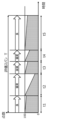
- FIG. 3 is a diagram for explaining information stored in the storage unit according to the embodiment. Figure 3 shows an image of the posture, posture characteristics, and posture features (lower back, neck, hip angle), the evaluation score, and the function are shown.
- the estimated posture of the subject 11 is classified into one of a plurality of reference postures based on the posture feature amount, and the posture is evaluated from the evaluation score or function corresponding to the reference posture.
- the posture is evaluated from the evaluation score or function corresponding to the reference posture.
- Other postures may be set so as to reduce their influence on the evaluation results by assigning 0 points, full points, or any point between them.
- FIG. 4 is a diagram for explaining posture evaluation according to another example of the embodiment.
- the horizontal axis shows the period (elapsed time) during which the posture of a certain subject 11 is being evaluated
- the vertical axis shows the quality of the posture, which is the evaluation result.
- the larger the value the better the posture.
- the posture of the subject 11 is evaluated for each evaluation span T (here, only one span is shown) shown at the top of the graph.
- the posture of the subject 11 is, among the reference postures shown in FIG. It has been shown that the patient takes a hunched posture during the period t5, and takes a good posture during the period t5.
- the evaluation value according to the accumulated fatigue is calculated.
- a is a numerical value determined empirically or experimentally.
- the function is set so that the fatigue accumulated per unit time is minimized (100 in this case) by the intercept of the function according to the standard posture corresponding to the changed posture. set, but not limited to this.
- the function only the slope may be defined, and a numerical value may be added in place of the intercept depending on the previous progress of fatigue (degree of decrease in the number of reference points).
- the number of reference points at the end of t2 has decreased to 25.
- the initial value of the reference score for the subsequent period may be set depending on the degree of decrease in the reference score for the immediately preceding period.
- a linear function was used as an example of the function, but a function other than the linear function may be suitable as a function for reducing the number of reference points. Therefore, an appropriate function may be determined experimentally depending on the characteristics of the subject 11 and the characteristics of each reference posture.
- the estimated posture of the subject 11 is compared with the reference posture based on the posture feature amount, and the estimated posture of the subject 11 is selected from among the plurality of prepared reference postures. Determine if it is equivalent. Then, the posture of the subject 11 can be determined to be in a good state by simply adding a preset score to one reference posture identified as the reference posture to which the estimated posture of the subject 11 corresponds. It is possible to quantify whether this is the case. That is, it becomes possible to appropriately evaluate the posture of the subject 11 through relatively simple processing.
- FIG. 5 is a diagram for explaining posture evaluation according to another example of the embodiment.
- the horizontal axis shows the period (elapsed time) during which the posture of a certain subject 11 is being evaluated
- the vertical axis shows the quality of the posture, which is the evaluation result.
- the larger the value the better the posture.
- the subject 11 has a good posture in the period t1, a hunched back in the period t2, and a good posture in the period t3 among the reference postures shown in FIG. It is shown that during the period t4, the patient takes a backward tilt, and during the period t5, the neck bends.
- This example shows an example in which the number of reference points is simply accumulated according to the cumulative time without reducing the number of reference points.
- the cumulative value is calculated by multiplying the standard score 100 by the cumulative time t1
- the cumulative value is calculated by multiplying the standard score 20 by the cumulative time t2
- the cumulative value is calculated by multiplying the standard score of 100 by the cumulative time t3
- the cumulative value is calculated by multiplying the standard score of 80 by the cumulative time t4
- the cumulative value is calculated by multiplying the standard score of 80 by the cumulative time t4.
- the cumulative value is calculated by multiplying the reference score 50 by the cumulative time t5.
- FIG. 6 is a diagram for explaining posture evaluation according to yet another example of the embodiment.
- the horizontal axis shows the period (elapsed time) during which the posture of a certain subject 11 is being evaluated
- the vertical axis shows the quality of the posture, which is the evaluation result.
- the larger the value the better the posture.
- This example shows an example in which an instantaneous posture evaluation value is output as an evaluation result without considering cumulative time. Therefore, as shown in the figure, the evaluation score of 100 points is output as is during the period of good posture, and the evaluation score of 20 points is output as is during the period of hunched posture. The evaluation score of 80 points is output as is during the period when the user is bending the neck, and the evaluation score of 50 points is output as is during the period when the neck is bent.
- the information that needs to be stored in the storage unit 110 differs depending on how the evaluation results are output. Therefore, if the storage unit 110 stores at least one of the evaluation score, reference score, and function in addition to the reference posture and posture feature amount, the posture evaluation shown in any of the above examples is possible. It becomes possible.
- the imaging device 201 is a device that images the subject 11 and outputs the image, and is realized by a camera.
- an existing camera such as a security camera or a fixed point camera may be used in the space to which the posture evaluation system 200 is applied, or a dedicated camera may be newly provided.
- Such an imaging device 201 is an example of an information output device that outputs an image as information regarding the position of a body part of the subject 11. Therefore, the output information is an image, and is information including the positional relationship of the body parts of the subject 11 on the projected image sensor.
- the clock device 202 is a device that measures time, and is realized by a clock.
- the clock device 202 can transmit the time to the second acquisition unit 102 to which it is connected.
- the time measured by the clock device 202 may be an absolute time, or may be a relative elapsed time from a starting point.
- the timing device 202 may be realized in any form as long as it can measure the time between two points in time (i.e., cumulative time): the point in time when the subject 11 is detected to be still and the point in time when the posture is changed.
- the reception device 204 is a user interface that receives input of personal information of the subject 11, and is realized by an input device such as a touch panel or a keyboard.
- the personal information includes at least one of age, gender, height, weight, muscle mass, stress level, body fat percentage, and exercise proficiency.
- the age of the target person 11 may be a specific numerical value, or may be an age range divided by 10 years, such as 10s, 20s, and 30s, and may be 59 years or younger or 60 years old or younger.
- the age range may be divided into two age ranges with a predetermined age as the boundary, such as 20 years old or older, or it may be other age ranges.
- the gender of the subject 11 is selected from either male or female, which is appropriate for the subject 11. Furthermore, the height and weight of the subject 11 are respectively accepted. Furthermore, as for the muscle mass, the composition ratio of the muscles of the subject 11 measured using a body composition meter or the like is accepted. Further, the stress level of the subject 11 is selected by the subject 11 himself from options such as high, medium, and low as the level of subjective stress that the subject 11 feels.
- the body fat percentage of the subject 11 is the ratio of the weight of body fat to the body weight of the subject 11, and is expressed, for example, as a percentage.
- the exercise proficiency level of the subject 11 may be quantified by the score obtained when the subject 11 executes a predetermined exercise program, or may be the state of the exercise that the subject 11 usually engages in.
- the former is quantified by, for example, the time required to perform back muscles 10 times, the time required to run 50 meters, the flight distance of a long throw, etc.
- the latter is quantified by, for example, how many days a week you exercise or how many hours you exercise.
- personal information is used for the purpose of improving the accuracy of posture evaluation, such as personal optimization of evaluation scores and functions, so it may be necessary to ensure sufficient accuracy or to realize the generalized posture evaluation system 200.
- the posture evaluation system 200 may be implemented without the reception device 204.
- the display device 205 is a device for displaying content based on the posture evaluation results output by the output unit 109.
- the display device 205 displays an image showing content based on the posture evaluation result using a display panel such as a liquid crystal panel or an organic EL (Electro Luminescence) panel.
- a display panel such as a liquid crystal panel or an organic EL (Electro Luminescence) panel.
- the content displayed by the display device 205 will be described later. Further, if the posture evaluation system 200 is configured to only reduce the fatigue level of the subject 11 using the recovery device 206, it is sufficient to include only the recovery device 206, and the display device 205 is Not required.
- the recovery device 206 is, for example, a device that reduces the degree of fatigue of the subject 11 by promoting blood circulation in the subject 11 when the posture evaluation result is unfavorable (when fatigue is likely to accumulate). .
- the recovery device 206 recovers the sitting subject 11 by applying voltage, pressurization, vibration, heating, etc., or by changing the arrangement of each part of the chair 12 by a mechanism provided in the chair 12. Actively change the posture of the person. Thereby, the recovery device 206 changes the load on at least one of the muscles and joints of the subject 11, and also promotes blood circulation. Also in terms of blood flow, by promoting blood circulation in this way, the influence of deterioration of blood flow due to the subject 11 being in a stationary posture is reduced, and the degree of fatigue is recovered.
- the recovery device 206 is pre-attached to or in contact with an appropriate body part of the subject 11, depending on the configuration of the device.
- the posture evaluation system 200 when promoting the blood circulation of the subject 11 by heating, the entire space around the subject 11 is heated, so in such a case, it is not necessary to attach or contact the appropriate body part of the subject 11. do not have. Further, when the posture evaluation system 200 is configured to only display the posture evaluation results for the subject 11, it is sufficient to include only the display device 205, and the recovery device 206 is not essential.
- FIG. 7 is a flowchart showing the posture evaluation method according to the embodiment.
- the posture evaluation system 200 first acquires the personal information of the subject 11 (step S101). Acquisition of the personal information is performed by the subject 11 himself or an administrator who manages the evaluation results of the subject 11's posture by inputting it into the reception device 204. The input personal information of the subject 11 is stored in the storage unit 110 or the like, and read out and used when evaluating the posture.
- the posture evaluation system 200 detects the subject 11 using the imaging device 201 (step S102). Detection of the subject 11 is performed by determining whether the subject 11 has entered the viewing angle of the camera, which is the imaging device 201. Note that at this time, the target person 11 may be a specific target person 11, or the target person 11 may be a person who falls within the viewing angle of the camera from among an unspecified number of people. When the target person 11 is selected from an unspecified number of people, input of personal information may be omitted. Moreover, when detecting a specific target person 11, a step of identifying the target person 11 by image recognition or the like is added.
- the subject 11 inputs personal information, and then presses the "start monitoring” button by operating the operating terminal at hand (which also serves as the display device 205) shown in FIG. 9A, for example.
- the screen changes to display that posture analysis is in progress (posture monitoring in progress), and at any time, the "View analysis results” button is displayed to display the analysis results. ” button is displayed. Further, in the screen display example shown in FIG. 9B, a "reset” button is displayed to discard the posture monitoring results accumulated so far.
- the posture is evaluated by understanding the detection area by the imaging device 201 and entering the detection area.
- the description will be made assuming a private booth 300 equipped with the posture evaluation device 100.
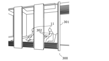
- FIG. 8 is an external view of the private booth according to the embodiment.
- the posture evaluation device 100 in this example is provided in a private booth 300 in which one (in some cases, two or more) subjects 11 enter and work etc. in the space.
- Each space is partitioned by a partition wall 301 to define a space in which the subject 11 can be accommodated. This makes it easier to define the position in space where the subject 11 is present, making it easier to optimize the arrangement of each component of the posture evaluation system 200, such as the imaging device 201.
- fixtures 302 such as chairs and desks are arranged within the space of the private booth 300. These fixtures 302 are configured to be able to be displaced according to the evaluation result of the posture of the subject 11. As an example, if the evaluation result of the posture of the subject 11 is relatively low and falls below the threshold for notification required, the fixture 302 can be displaced to prompt the subject to change the posture. Furthermore, it may be apparent from the estimated posture of the subject 11 that the position of the fixture 302 is not appropriate. For example, if the subject 11 has a hunched posture, it may be inferred that the arrangement of the work computer display is inappropriate. In this case, the chair among the fixtures 302 may be moved to utilize its lifting and lowering functions.
- the arrangement of the interface device of the work computer is not appropriate.
- the desk may be moved to utilize its lifting and lowering functions.
- the private booth 300 is assigned to each individual subject 11, so image recognition, etc. is not necessary, and the degree of fatigue is determined by taking personal information into consideration. is estimated.
- step S102 If it is determined that the subject 11 is not detected (No in step S102), the posture evaluation system 200 repeats step S102 until the subject 11 is detected.
- the image output by the imaging device 201 is acquired by the first acquisition unit 101 (step S103, an example of an acquisition step).
- step S104 when it is detected that the subject 11 is standing still (in a stationary posture) in the acquired image (step S104), the posture of the subject 11 is estimated in the evaluation device 100.
- the posture estimation unit 105 estimates the posture of the subject 11 based on the acquired image, and calculates posture feature amounts (posture estimation step S106).
- step S108 based on the time acquired by the second acquisition unit 102, the cumulative time of the subject 11 in a static posture is measured (step S108). Next, it is determined whether the stationary state has been released or not, depending on whether the posture estimated by the posture estimation unit 105 has changed from a certain stationary posture (step S110).
- step S110 If it is not determined that the stationary state has been released (No in step S110), the process returns to step S108 and continues measuring the cumulative time.
- the evaluation unit 108 corresponds the calculated posture feature amount of the posture of the subject 11 to each of the plurality of stored reference postures.
- the posture of the subject 11 is evaluated by comparing it with the posture feature amount (step S112).
- the evaluation of the posture is as described using FIGS. 4 to 6, so the description thereof will be omitted here.
- the evaluation unit 108 outputs a posture evaluation result. After that, the process returns to step S106 and similar processing is performed for the new posture.
- the evaluation unit 108 stores, for example, the evaluation results (cumulative values) for the cumulative time in the storage unit 110 or the like, and each time the evaluation span T elapses, the evaluation unit 108 adds up the cumulative values output within the evaluation span. Then, it is output to the output unit 109 as an evaluation result.
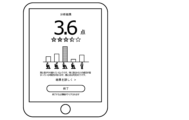
- the subject 11 operates the operating terminal on the screen shown in FIG. 9B and presses the "View Analysis Results” button. Then, as shown in FIG. 9C, numerical results indicating the evaluation results are displayed.
- the evaluation result is 72%, or 3.6 points, compared to 5 points when there is no fatigue at all.
- the screen in FIG. 9C includes a link for displaying a detailed page of the results with the text "Results in detail” for displaying the evaluation results in more detail.
- an "end” button is displayed for ending the analysis. When the "end” button is pressed, various types of information acquired for posture evaluation are deleted (cleared).
- FIG. 9D shows an entire page that is a combination of partial pages that are displayed one part at a time on the screen of the display device 205.
- an arbitrary partial page is displayed by performing an operation (such as a scrolling operation) to display an arbitrary part of the entire page.
- the information displayed in the display example of the screen of FIG. 9C is displayed in a different display format, and the state of fatigue of each body part of the subject 11 is also displayed.
- a play button etc. for playing a video prepared in advance which indicates what action to take, is displayed.
- changes in the degree of fatigue accumulated for each body part of the subject 11 are displayed.
- the evaluation device 100 includes a plurality of reference postures that serve as standards used for posture evaluation, and posture feature amounts corresponding to each of the plurality of reference postures.
- a first acquisition unit 101 acquisition unit
- the posture estimation unit 105 calculates the posture of the subject 11 by comparing the calculated posture feature amount of the posture of the subject 11 with the posture feature amount corresponding to each of a plurality of stored reference postures.
- An evaluation unit 108 that performs evaluation and outputs an evaluation result is provided.
- Such an evaluation device 100 can evaluate the posture of the subject 11 by comparing the posture of the subject 11 with a reference posture stored in advance in the storage unit 110 to determine which of a plurality of reference postures the subject 11 corresponds to. can. Compared to the case where the posture of the subject 11 is directly evaluated using numerical values, it is only necessary to calculate which of the reference postures the posture of the subject 11 corresponds to, so it is possible to evaluate the subject 11 by relatively simple calculations. The posture of the person 11 can be evaluated. Therefore, posture can be evaluated more appropriately from the viewpoint of processing resources required for posture evaluation.
- the evaluation device 100 according to the second aspect of the present disclosure is the evaluation device 100 according to the first aspect, and the storage unit 110 stores a plurality of reference postures and a plurality of reference postures corresponding to each of the plurality of reference postures. Posture feature amounts and evaluation scores corresponding to each of a plurality of reference postures are stored in advance, and the evaluation unit 108 identifies a reference posture corresponding to the calculated posture of the subject 11 and performs evaluation points corresponding to the calculated posture of the subject 11. The evaluation score may be output as the evaluation result.
- the posture of the subject 11 can be evaluated based on the evaluation score associated with each reference posture.
- the evaluation device 100 according to the third aspect of the present disclosure is the evaluation device 100 according to the first or second aspect
- the storage unit 110 stores a plurality of reference postures and each of the plurality of reference postures.
- the posture feature amount corresponding to the posture and the evaluation score corresponding to each of a plurality of reference postures are stored in advance, and the evaluation unit 108 identifies the reference posture corresponding to the calculated posture of the subject 11, and A cumulative value obtained by multiplying the evaluation score corresponding to the posture by a cumulative time indicating the period during which the posture of the subject 11 is maintained may be output as the evaluation result.
- the posture of the subject 11 can be evaluated based on the evaluation score associated with each reference posture. At that time, it is possible to output an evaluation result that takes into account the period (cumulative time) during which the posture of the subject 11 is maintained.
- the evaluation device 100 according to the fourth aspect of the present disclosure is the evaluation device 100 according to any one of the first to third aspects, in which the evaluation unit 108 is configured to perform posture evaluation in a unit period.
- the total cumulative value per certain evaluation span may be output as the evaluation result.
- the evaluation device 100 according to the fifth aspect of the present disclosure is the evaluation device 100 according to any one of the first to fourth aspects, and the storage unit 110 stores a plurality of reference postures and a plurality of reference postures. posture features corresponding to each of the reference postures, the number of reference points corresponding to each of the plurality of reference postures, and the cumulative time that is a function corresponding to each of the plurality of reference postures and indicating the period during which the posture is maintained.
- a function for reducing the number of reference points according to the length of is stored in advance, and the evaluation unit 108 identifies a reference posture corresponding to the calculated posture of the subject 11, and determines a reference posture corresponding to the calculated posture of the subject 11.
- the cumulative value of the reference score for the cumulative time may be output as the evaluation result.
- the posture of the subject 11 can be evaluated based on the reference scores associated with each reference posture. At that time, it is possible to output an evaluation result that takes into account the period (cumulative time) during which the posture of the subject 11 is maintained. Normally, the longer the cumulative time, the more fatigue accumulates even in the same posture (it can be considered as a worse posture than at the beginning of the period), so by reducing the reference score by a function, It becomes possible to reflect in the evaluation results the deterioration of the posture caused by the posture being maintained.
- the evaluation device 100 according to the sixth aspect of the present disclosure is the evaluation device 100 according to the fifth aspect, in which the evaluation unit 108 calculates the cumulative value per evaluation span, which is a unit period for evaluating the posture. The total may be output as the evaluation result.
- the private booth 300 includes the evaluation device 100 described in any one of the above and a partition wall 301 having a space therein in which the subject 11 is accommodated.
- the posture of the subject 11 accommodated in the space can be more appropriately evaluated.
- the private booth 300 in the eighth aspect of the present disclosure is the private booth 300 according to the seventh aspect, in which fixtures 302 for use by the subject 11 are installed in the space, and the fixtures 302 are displaced. By doing so, notifications may be made according to the evaluation results.
- the evaluation result of the posture of the subject 11 accommodated in the space can be notified by the displacement of the fixture 302.
- the posture evaluation method is a posture evaluation method executed by a computer, and includes a plurality of reference postures serving as a reference used for posture evaluation, and a posture evaluation method corresponding to each of the plurality of reference postures.
- Posture features are stored in advance, information regarding the position of the subject's body parts is acquired, the posture features in the subject's posture are calculated based on the information, and the posture features in the calculated subject's posture are calculated.
- the posture of the subject is evaluated by comparing it with posture feature amounts corresponding to each of a plurality of stored reference postures, and the evaluation result is output.
- the processing executed by a specific processing unit may be executed by another processing unit.
- the order of the plurality of processes may be changed, or the plurality of processes may be executed in parallel.
- the posture evaluation system or evaluation device may be realized by a plurality of devices each having some of the plurality of components, or may be realized by a single device having all of the plurality of components. good.
- some of the functions of a component may be realized as functions of another component, and each function may be distributed to each component in any manner. Any form having a configuration that is equipped with all the functions that can substantially realize the posture evaluation system or evaluation device of the present disclosure is included in the present disclosure.
- each component may be realized by executing a software program suitable for each component.
- Each component may be realized by a program execution unit such as a CPU or a processor reading and executing a software program recorded on a recording medium such as a hard disk or a semiconductor memory.
- each component may be realized by hardware.
- each component may be a circuit (or integrated circuit). These circuits may constitute one circuit as a whole, or may be separate circuits. Further, each of these circuits may be a general-purpose circuit or a dedicated circuit.
- the general or specific aspects of the present disclosure may be implemented in a system, apparatus, method, integrated circuit, computer program, or computer-readable recording medium such as a CD-ROM. Further, the present invention may be realized by any combination of a system, an apparatus, a method, an integrated circuit, a computer program, and a recording medium.
- the posture of the subject is estimated from the image using a rigid link model generated by image recognition, but the method for estimating the posture is not limited to this. Any existing method may be used to estimate the posture of the subject from the image.
- a method of combining measurement results from pressure sensors may be applied to the content of the present application.
- the pressure sensor is a sensor that has a detection surface, and measures the pressure applied to each of the unit detection surfaces that divide the detection surface into one or more units. The pressure sensor thus measures the pressure for each unit detection surface and outputs the pressure distribution on the detection surface.
- the pressure sensor is provided so that the subject is positioned on the detection surface. For example, the pressure sensor is provided on the seat and backrest of a chair on which the subject is seated.
- the pressure sensor may have a marker on the detection surface and guide the subject onto the detection surface by displaying a message such as "Please sit on the marker.” Furthermore, by guiding the subject onto the detection surface of the pressure sensor provided on a portion of the floor in this manner, the pressure sensor may output the pressure distribution of the subject on the floor. For example, when biased pressure is applied, the output pressure distribution is used to correct the estimated posture so that the bias is formed in the posture estimated based on the image.
- FIG. 10 is a diagram illustrating posture estimation according to a modification of the embodiment. As shown in FIG. 8, in this modification, the posture of the subject 11 is estimated using a sensor module 207 including a position sensor 207a and a potential sensor 207b.
- a sensor module 207 including a position sensor 207a and a potential sensor 207b.
- a plurality of sensor modules 207 are attached to the subject 11, but the number of sensor modules 207 attached to the subject 11 is not particularly limited. Only one sensor module 207 may be attached to the subject 11.
- the manner in which the sensor module 207 is worn there is no particular limitation on the manner in which the sensor module 207 is worn, and any manner may be used as long as the position of a predetermined body part of the subject 11 can be measured.
- a plurality of sensor modules 207 are attached to the subject 11 by wearing a costume to which a plurality of sensor modules 207 are attached.
- the sensor module 207 is a device that is attached to a predetermined body part of the subject 11 and outputs information indicating the result of detection or measurement in conjunction with the predetermined body part. Specifically, the sensor module 207 outputs a position sensor 207a that outputs position information regarding the spatial position of a predetermined body part of the subject 11, and potential information that indicates the potential at the predetermined body part of the subject 11. It has a potential sensor 207b. In the figure, a sensor module 207 having both a position sensor 207a and a potential sensor 207b is shown, but as long as the sensor module 207 has the position sensor 207a, the potential sensor 207b is not essential.
- the position sensor 207a in the sensor module 207 is an example of an information output device that outputs position information as information regarding the position of the body part of the subject 11. Therefore, the output information is position information, and is information including the relative or absolute position of a predetermined body part of the subject 11. Furthermore, the output information may include, for example, potential information.
- the potential information is information including the value of the potential measured at a predetermined body part of the subject 11. The position information and the potential information will be explained in detail below along with the position sensor 207a and the potential sensor 207b.
- the position sensor 207a detects the spatial relative position or absolute position of a predetermined body part of the subject 11 to whom the sensor module 207 is attached, and outputs information regarding the spatial position of the predetermined body part as a detection result. It is a vessel.
- the information regarding the spatial position includes information that allows the position of a body part in the space to be specified as described above, and information that allows the change in the position of the body part due to body movement to be specified.
- the information regarding the spatial position includes the position of the joint and the skeleton in space, and information indicating a change in the position.
- the position sensor 207a is configured by combining various sensors such as an acceleration sensor, an angular velocity sensor, a geomagnetic sensor, and a distance sensor. Since the position information output by the position sensor 207a can approximate the spatial position of a predetermined body part of the subject 11, the posture of the subject 11 can be estimated from the spatial position of the predetermined body part.
- the potential sensor 207b is a detector that measures the potential at a predetermined body part of the subject 11 to whom the sensor module 207 is attached, and outputs information indicating the potential of the predetermined body part as a measurement result.
- the potential sensor 207b is a measuring instrument that has a plurality of electrodes and measures the potential generated between the plurality of electrodes using an electrometer.
- the potential information output by the potential sensor indicates the potential generated in a predetermined body part of the subject 11, and since the potential corresponds to the action potential of a muscle in the predetermined body part, The accuracy of estimating the posture of the subject 11 estimated from the electric potential etc. can be improved.
- the fatigue estimation system in this modification estimates the degree of fatigue of the subject 11 using the posture of the subject 11 estimated as described above. Note that the processing after estimating the posture of the subject 11 is the same as that in the above embodiment, so a description thereof will be omitted.
- the information output device is attached to a predetermined body part of the subject 11, and outputs position information regarding the spatial position of the predetermined body part as information regarding the position of the body part of the subject 11.
- the evaluation device 100 estimates the posture of the subject 11 based on the position information output by the position sensor 207a.
- the degree of fatigue of the subject 11 can be estimated using the position information output by the position sensor 207a.
- the posture of the subject 11 estimated from the output information is used. Specifically, the accumulation of fatigue caused by maintaining a constant static posture is quantified as the degree of fatigue based on the duration of time that has passed in a static posture in which the subject 11 is stationary.
- the fatigue level of the subject 11 is calculated based on the detection and measurement results at 207 by the sensor module, taking into account the duration of the stationary posture. It is possible to estimate the degree of fatigue of the subject 11 in a stationary posture with less burden and with higher accuracy.
- the present disclosure may be realized as a posture evaluation method executed by a posture evaluation system or an evaluation device.
- the present disclosure may be realized as a program for causing a computer to execute such a fatigue estimation method, or may be realized as a computer-readable non-temporary recording medium in which such a program is recorded. .
Abstract
姿勢評価装置(評価装置(100))は、姿勢の評価に用いられる基準となる複数の基準姿勢と、複数の基準姿勢のそれぞれに対応する姿勢特徴量とが予め記憶されている記憶部(110)と、対象者(11)の身体部位の位置に関する情報を取得する取得部(第1取得部(101))と、情報に基づいて、対象者(11)の姿勢における姿勢特徴量を算出する姿勢推定部(105)と、算出した対象者(11)の姿勢における姿勢特徴量を、記憶されている複数の基準姿勢のそれぞれに対応する姿勢特徴量と比較することにより、対象者(11)の姿勢を評価し、評価結果を出力する評価部(108)と、を備える。
Description
本開示は、対象者の姿勢を評価するための姿勢評価装置及び姿勢評価方法、ならびに、当該姿勢評価装置等が使用される個室ブースに関する。
近年、疲労の蓄積から体調不良をはじめ、怪我及び事故等につながるといった事例が散見される。これに対して、疲労の程度を推定することにより、体調不良、怪我及び事故等を未然に防ぐ技術に注目されるようになった。例えば、疲労度を推定するための疲労推定システムとして、特許文献1には、力計測、及び生体電気インピーダンス計測に基づいて疲労の有無及び疲労の種類を判定する、疲労判定装置が開示されている。
ところで、上記特許文献1に例示される従来の疲労判定装置等では、疲労度の観点での姿勢の評価として適切でない場合がある。そこで、本開示では、より適切に姿勢を評価する姿勢評価装置等を提供する。
本開示の一態様に係る姿勢評価装置は、姿勢の評価に用いられる基準となる複数の基準姿勢と、前記複数の基準姿勢のそれぞれに対応する姿勢特徴量とが予め記憶されている記憶部と、対象者の身体部位の位置に関する情報を取得する取得部と、前記情報に基づいて、前記対象者の姿勢における姿勢特徴量を算出する姿勢推定部と、算出した前記対象者の姿勢における姿勢特徴量を、記憶されている前記複数の基準姿勢のそれぞれに対応する姿勢特徴量と比較することにより、前記対象者の姿勢を評価し、評価結果を出力する評価部と、を備える。
また、本開示の一態様に係る個室ブースは、上記に記載の姿勢評価装置と、前記対象者が収容される空間を内部に有する隔壁と、を備える。
また、本開示の一態様に係る姿勢評価方法は、コンピュータに実行される姿勢評価方法であって、姿勢の評価に用いられる基準となる複数の基準姿勢と、前記複数の基準姿勢のそれぞれに対応する姿勢特徴量とを予め記憶させ、対象者の身体部位の位置に関する情報を取得し、前記情報に基づいて、前記対象者の姿勢における姿勢特徴量を算出し、算出した前記対象者の姿勢における姿勢特徴量を、記憶されている前記複数の基準姿勢のそれぞれに対応する姿勢特徴量と比較することにより、前記対象者の姿勢を評価し、評価結果を出力する。
本開示の一態様に係る姿勢評価装置等は、より適切に姿勢を評価することができる。
以下、実施の形態について、図面を参照しながら具体的に説明する。なお、以下で説明する実施の形態は、いずれも包括的又は具体的な例を示すものである。以下の実施の形態で示される数値、形状、材料、構成要素、構成要素の配置位置及び接続形態、ステップ、ステップの順序などは、一例であり、本開示を限定する主旨ではない。また、以下の実施の形態における構成要素のうち、独立請求項に記載されていない構成要素については、任意の構成要素として説明される。
なお、各図は模式図であり、必ずしも厳密に図示されたものではない。また、各図において、実質的に同一の構成に対しては同一の符号を付し、重複する説明は省略または簡略化される場合がある。
(実施の形態)
[姿勢評価装置を含むシステム構成]
以下、実施の形態に係る姿勢評価装置を含む姿勢評価システムの全体構成について説明する。図1Aは、実施の形態に係る姿勢の評価を説明するための第1図である。図1Bは、実施の形態に係る姿勢の評価を説明するための第2図である。
[姿勢評価装置を含むシステム構成]
以下、実施の形態に係る姿勢評価装置を含む姿勢評価システムの全体構成について説明する。図1Aは、実施の形態に係る姿勢の評価を説明するための第1図である。図1Bは、実施の形態に係る姿勢の評価を説明するための第2図である。
本開示における姿勢評価システム200(後述する図2参照)は、実施の形態では、撮像装置201を用いた対象者11の撮像によって出力された画像を用いて、当該対象者11における姿勢の評価するシステムである。撮像装置201は、対象者11を撮像して画像を出力するカメラであればその形態に限定はなく、図1Aに示すように、建物等の壁面又は天井等に設置される固定式のカメラであってもよく、対象者11が操作するPC、スマートフォン、又はタブレット端末等に搭載されたカメラであってもよい。
ここで対象者は、椅子12に着座した姿勢である。本開示における姿勢評価システム200では、対象者11における疲労のうち、姿勢が固定された静止姿勢をとることによって蓄積する疲労をもとに対象者11の姿勢を評価する。これはつまり、姿勢が固定された状態により、筋肉及び関節の少なくとも一方における負荷ならびに悪化する血流(以下、血流量の低下ともいう)によって蓄積される疲労に基づいて、姿勢の評価を行っている。したがって、対象者11は、少なくとも一定の期間において座位、臥位又は立位で静止した静止姿勢である。一定の期間とは、例えば、数十秒又は数秒等、姿勢評価システム200において姿勢の評価が可能な最小の期間である。このような期間は、姿勢評価システム200を構成する撮像装置201及び評価装置100(後述する図2参照)による処理能力に依存して決定される。
このような静止姿勢をとる対象者11としては、例えば、オフィスにおけるデスクワーカ、移動体を操舵するドライバ、静止姿勢での負荷を利用した筋力トレーニングを行う者、病院等の施設の入所者、飛行機等の乗客及び乗員等が挙げられる。
撮像装置201によって撮像され、出力された画像は、評価装置100によって処理され、図1Bに示すように対象者11の姿勢が推定される。推定された対象者11の姿勢は、一例として剛体リンクモデル11bとして出力される。具体的には、図1Bに示すように、直線で示す骨格が黒点で示す関節によって接続され、一つの関節によって接続される二つの骨格同士の位置関係によって、対象者11の姿勢を再現できる。姿勢の推定は、画像認識によって行われ、関節と骨格との位置関係に基づき、上記の剛体リンクモデル11bとして出力される。
推定された剛体リンクモデル11bでは、関節を介して隣り合う骨格同士のなす角度を算出することができる。以下では、このような角度を、当該姿勢における姿勢特徴量と呼ぶ。姿勢特徴量は、1つの姿勢に対して、複数の組合せの骨格同士のなす角度を含んでいる。例えば、姿勢特徴量は、首の角度、腰の角度、及び、股関節角度等を含む。言い換えると、これらの複数の組合せの骨格同士のなす角度によって、1つの姿勢が規定される。このように、本実施の形態では、姿勢の推定とは、姿勢特徴量を算出することを意味する。推定された姿勢の姿勢特徴量には、推定された姿勢に応じた角度の関係に骨格同士を維持するために、個々の身体部位の筋肉及び関節の少なくとも一方にかかる負荷量に相当する姿勢の評価が可能となる。ここで、各々の身体部位の筋肉及び関節の少なくとも一方における負荷量は、上記静止姿勢が継続された継続時間(言い換えると、同じ姿勢が維持されることで疲労が累積される累積時間)が延びるほど蓄積されるため、累積時間を用いた演算によって対象者11が静止姿勢を維持することによる疲労度が算出される。なお、以降の説明では、「筋肉及び関節の少なくとも一方」を「筋肉及び/又は関節」とも表現する。
また、本実施の形態では、上記の筋肉及び/又は関節にかかる負荷の量を、対象者11の血流の悪化度と読み替えてもよい。
すなわち、姿勢評価システム200は、対象者11の姿勢を推定した後、当該姿勢の累積時間に基づいて、対象者11の筋肉への負荷量、関節への負荷量、及び血流の悪化度の少なくとも一つの観点で蓄積される疲労に応じた姿勢の評価を行う。
なお、血流の悪化度は、上昇するほど対象者11の血流量が低下していることを意味し、血流量の低下によって引き起こされる疲労の程度が高まる。
また、以降の対象者11の姿勢の評価では、当該姿勢から推定される筋肉への負荷量、関節への負荷量、及び血流の悪化度の少なくとも一つに基づいて蓄積される疲労の観点で姿勢の評価を行うが、姿勢と紐づけられる評価値(評価点数)としては、アンケート等のデータを蓄積することで生成された、対象者11の主観に基づく主観評価値が用いられる。なお、評価値としては、他に、筋肉への負荷量、関節への負荷量、及び血流の悪化度の実測データによって算出されてもよい。この実測データは、つまり、姿勢ごとに計測された、筋肉への負荷量、関節への負荷量、及び血流量の実測値を姿勢と対応付けて蓄積することで構築されたデータベースである。この場合の姿勢評価システム200では、推定された対象者11の姿勢の評価を、筋肉への負荷量、関節への負荷量、及び血流量の実測値に基づく評価によって行うことができる。
実測データは、対象者11の個人差を考慮して、個人ごとの実測値を用いて構築されてもよく、不特定多数の被検者から得られたビッグデータについて、統計解析、又は機械学習等の解析処理によって対象者11ごとに適合するよう、適格化して構築されてもよい。
次に、本開示における姿勢評価システム200の機能構成について、図2を用いて説明する。図2は、実施の形態に係る姿勢評価システムの機能構成を示すブロック図である。
図2に示すように、本開示における姿勢評価システム200は、評価装置100、撮像装置201、計時装置202、受付装置204、表示装置205、及び回復装置206を備える。
評価装置100は、姿勢評価装置の一例であり、第1取得部101と、第2取得部102と、第3取得部103と、姿勢推定部105と、評価部108と出力部109と、記憶部110と、を備える。
第1取得部101は、撮像装置201に接続され、撮像装置201から対象者11が撮像された画像を取得する通信モジュールである。つまり、第1取得部101は、取得部の一例である。第1取得部101と撮像装置201との接続は、有線又は無線によって行われ、当該接続を介して行われる通信の方式にも特に限定はない。
第2取得部102は、計時装置202に接続され、計時装置202から時間を取得する通信モジュールである。第2取得部102と計時装置202との接続は、有線又は無線によって行われ、当該接続を介して行われる通信の方式にも特に限定はない。
第3取得部103は、受付装置204に接続され、受付装置204から個人情報を取得する通信モジュールである。第3取得部103と受付装置204との接続は、有線又は無線によって行われ、当該接続を介して行われる通信の方式にも特に限定はない。
姿勢推定部105は、プロセッサ及びメモリを用いて所定のプログラムが実行されることにより実現される処理部である。姿勢推定部105の処理により、第1取得部101において取得された画像に基づいて、対象者11の姿勢が推定される。つまり、姿勢推定部105は、対象者11のその時の姿勢における姿勢特徴量を算出する処理単位時間ごとに算出する。
評価部108は、プロセッサ及びメモリを用いて所定のプログラムが実行されることにより実現される処理部である。評価部108は、姿勢推定部105において推定された姿勢と、第2取得部102において取得された時間とを用いて、推定された姿勢の累積時間に基づいて、対象者11の姿勢を評価する。評価部108は、評価結果を出力部109へと出力する。
出力部109は、表示装置205及び回復装置206に接続され、評価装置100による姿勢の評価結果に基づく内容を表示装置205及び回復装置206に出力する通信モジュールである。出力部109と表示装置205又は回復装置206との接続は、有線又は無線によって行われ、当該接続を介して行われる通信の方式にも特に限定はない。
記憶部110は、姿勢の評価に用いられる基準となる複数の基準姿勢を、複数の基準姿勢のそれぞれに対応する姿勢特徴量とともに記憶する記憶装置である。記憶部110には、予め基準姿勢ごとに推定された疲労度によって、疲労の蓄積し難さが高いほどその姿勢の評価結果が良好となるように点数が、対応する基準姿勢及び、姿勢特徴量とともに記憶されている。上記の点数は、単に数値である場合もあるし、累積時間に応じた数値が算出可能な基準点数及び累積時間の長さに応じて当該基準点数を減少させるための関数の組合せの場合もある。この点数について、記憶部110に記憶されている各種の情報とともに、さらに詳しく説明する。図3は、実施の形態に係る記憶部に記憶される情報について説明するための図である。図3では、6種類の基準姿勢(良姿勢、首曲げ、猫背、前傾、後傾、及び、反り腰)のそれぞれについて、姿勢のイメージ図、姿勢の特徴、姿勢特徴量(腰、首、股関節の角度)、評価点数、及び、関数が示されている。
本実施の形態では、推定した対象者11の姿勢を、姿勢特徴量によって複数の基準姿勢のいずれか1つに分類し、その基準姿勢に対応する評価点数、又は、関数から、姿勢を評価する。また、図3には示されていないが、基準姿勢のいずれにも該当しない場合に、対象者11の姿勢を分類するためのその他の姿勢が存在する。その他の姿勢は、0点、満点、又はその間の任意の点のいずれかが付されるようにすることで、評価結果への影響が少なくなるように設定されていればよい。
例えば、対象者11の姿勢の評価は、以下のようにして行われてもよい。図4は、実施の形態の別例に係る姿勢の評価について説明するための図である。図4では、横軸に、ある対象者11の姿勢の評価を行っている期間(経過時間)を示し、縦軸に、その評価結果である姿勢の良否が示されている。縦軸では、数値が大きいほど姿勢がよい状態であることを示している。
この例では、グラフ上部に示す評価スパンT(ここでは1スパンのみを示している)ごとに、対象者11の姿勢の評価を行っている。図中の評価スパンでは、対象者11の姿勢は、図3に示す基準姿勢のうち、t1の期間において良姿勢をとり、t2の期間において猫背をとり、t3の期間において後傾をとり、t4の期間において猫背をとり、t5の期間において良姿勢をとることが示されている。この結果、t1の期間では、図3に示す関数(y=-ax+100、ただし、a>0)を用いて、当該関数の0~t1分の積分値をとることで、基準点数である100から単位時間ごとに傾き-aで基準点数が減少していく(姿勢の評価が悪化していく、あるいは、蓄積する疲労が増加していく)中で、蓄積されていく疲労に応じた評価値を数値化することができる。逆に言えば、累積される疲労の少なさに応じた累積値を数値化することができる。なお、aは、経験的又は実験的に決定される数値である。
同様に、t2の期間では、図3に示す関数(y=-2ax+100、ただし、a>0)を用いて、当該関数の0~t2分の積分値をとることで、基準点数である100から単位時間ごとに傾き-2aで基準点数が減少していく中で、累積される疲労の少なさに応じた累積値を数値化することができる。以下、t3~t5において同様である。そして、t1~t5までの評価スパンにおいて累積値を合計することで、累積された疲労の合計の少なさに対応する姿勢の総合的な評価値を算出することができる。そして、仮に、基準点数が減少しない(疲労が全くない)状況で、評価スパンを過ごした場合の総合的な評価値を100とした場合に、算出された実際の総合的な評価値が何パーセントであるかを算出して、評価結果として出力することができる。
この例では、姿勢が変更されるごとに、変更後の姿勢に対応する基準姿勢に応じた関数の切片によって、単位時間当たりに蓄積される疲労が最小(ここでは100)となるように関数が設定されているが、これに限られない。例えば、関数は、傾きのみが規定された状態で、その前の疲労の進行具合(基準点数の減少度合い)に応じて切片に代わる数値が加算されるようにしてもよい。例えば、図中のt2の期間において、t2の終了時点での基準点数は25まで減少している。このとき、姿勢の変更がされた場合に50だけ基準点数を加算するとしていれば、t3の期間では、25+50=75の基準点数から減少が始まるようになる。このとき、t3の期間の関数としては、y=-1.3ax+75となる。以上のようにして、直前の期間における基準点数の減少度合いに応じて、続く期間の基準点数の初期値が設定されてもよい。
また、この例では、関数として1次関数を例に挙げて説明したが、基準点数の減少のための関数としては、1次関数以外の関数が適している場合もある。そのため、対象者11の特性や基準姿勢ごとの特性に応じて、適切な関数を実験的に決定するなどしてもよい。
以上のようにして、本実施の形態では、推定された対象者11の姿勢を、基準姿勢と、姿勢特徴量に基づいて比較して、複数用意された基準姿勢のうちのいずれの基準姿勢に相当するか特定する。そして、推定された対象者11の姿勢が相当する基準姿勢として特定された1つの基準姿勢に対して、予め設定された点数を加算などするのみで、対象者11の姿勢が良好な状態であるか否かを数値化することが可能である。すなわち、比較的簡易な処理によって適切に、対象者11の姿勢を評価することが可能となる。
また、例えば、対象者11の姿勢の評価は、以下のようにして行われてもよい。図5は、実施の形態の別例に係る姿勢の評価について説明するための図である。図5では、横軸に、ある対象者11の姿勢の評価を行っている期間(経過時間)を示し、縦軸に、その評価結果である姿勢の良否が示されている。縦軸では、数値が大きいほど姿勢がよい状態であることを示している。
図中の1つ目の評価スパンでは、対象者11の姿勢は、図3に示す基準姿勢のうち、t1の期間において良姿勢をとり、t2の期間において猫背をとり、t3の期間において良姿勢をとり、t4の期間において後傾をとり、t5の期間において首曲げをとることが示されている。この例では、基準点数が減少されることなく、単に累積時間に応じて基準点数が累積される例を示している。したがって、t1の期間では、基準点数100に、累積時間であるt1を乗じて累積値を算出し、t2の期間では、基準点数20に、累積時間であるt2を乗じて累積値を算出し、t3の期間では、基準点数100に、累積時間であるt3を乗じて累積値を算出し、t4の期間では、基準点数80に、累積時間であるt4を乗じて累積値を算出し、t5の期間では、基準点数50に、累積時間であるt5を乗じて累積値を算出する。その後、同様にt1~t5までの評価スパンにおいて累積値を合計することで、累積された疲労の合計の少なさに対応する姿勢の総合的な評価値を算出し、基準点数が減少しない状況で、評価スパンを過ごした場合の総合的な評価値を100とした場合に、算出された実際の総合的な評価値が何パーセントであるかを算出して、評価結果として出力することができる。
また、例えば、対象者11の姿勢の評価は、以下のようにして行われてもよい。図6は、実施の形態のさらに別例に係る姿勢の評価について説明するための図である。図6では、横軸に、ある対象者11の姿勢の評価を行っている期間(経過時間)を示し、縦軸に、その評価結果である姿勢の良否が示されている。縦軸では、数値が大きいほど姿勢がよい状態であることを示している。
この例では、累積時間を考慮することなく、瞬間的な姿勢の評価値を評価結果として出力する例を示している。したがって、図中に示すように、良姿勢をとっている期間は評価点数である100点がそのまま出力され、猫背をとっている期間は評価点数である20点がそのまま出力され、後傾をとっている期間は評価点数である80点がそのまま出力され、首曲げをとっている期間は評価点数である50点がそのまま出力される。
以上のように、評価結果をどのように出力するかに応じて、記憶部110に記憶されている必要がある情報が異なる。したがって、記憶部110には、基準姿勢及び姿勢特徴量の他に、評価点数、基準点数、関数のうち、すくなくともいずれかが記憶されていれば、上記のいずれかの例に示す姿勢の評価が可能となる。
再び図2を参照して、撮像装置201は、上記したように、対象者11を撮像して画像を出力する装置であり、カメラによって実現される。撮像装置201として、防犯カメラ、定点カメラ等の姿勢評価システム200を適用する空間に既存のカメラが用いられてもよく、専用のカメラが新たに設けられてもよい。このような撮像装置201は、画像を対象者11の身体部位の位置に関する情報として出力する情報出力装置の一例である。したがって、出力される情報は、画像であり、対象者11の身体部位の、投影された撮像素子上での位置関係を含む情報である。
計時装置202は、時間を計測する装置であり、時計によって実現される。計時装置202は、接続された第2取得部102へと時間を送信可能である。ここで、計時装置202によって計測される時間とは、絶対的な時刻であってもよく、相対的な起点からの経過時間であってもよい。計時装置202は、対象者11の静止を検出した時点と、姿勢が変更される時点との2時点の間の時間(つまり累積時間)が計測できればどのような形態で実現されてもよい。
受付装置204は、対象者11の個人情報の入力を受け付けるユーザインタフェースであり、タッチパネル又はキーボード等の入力装置によって実現される。個人情報は、年齢、性別、身長、体重、筋肉量、ストレス度、体脂肪率、及び運動に対する習熟度のうち少なくとも一つを含む。対象者11の年齢は、具体的な数値であってもよく、10代、20代、及び30代のように、10歳ごとに区分された年齢帯であってもよく、59歳以下又は60歳以上のように所定の年齢を境とした二区分の年齢帯であってもよく、その他であってもよい。
また、対象者11の性別は、男性又は女性の二者のうちから選択される、対象者11に適切な一方である。また、身長及び体重は、対象者11の身長及び体重の数値がそれぞれ受け付けられる。また、筋肉量は、体組成計等を用いて計測された対象者11の筋肉の組成比率が受け付けられる。また、対象者11のストレス度は、対象者11が感じる主観的なストレスの程度として、高度、中度及び低度等の選択肢の中から対象者11自身によって選択される。
また、対象者11の体脂肪率は、対象者11の体重に占める体脂肪の重量の比率であり、例えば、100分率等で表現される。
また、対象者11の運動に対する習熟度は、所定の運動プログラムを対象者11が実施した際のスコアで定量化されていてもよく、対象者11が普段取り組む運動の状況であってもよい。前者では、例えば、背筋を10回行うのに要した時間、50mを走るのに要した時間、遠投の飛距離等によって定量化される。後者では、例えば、一週間に何日運動を行うか、又は何時間運動を行うか等によって定量化される。なお、個人情報は、評価点数及び関数の個人最適化など、姿勢の評価の精度を向上する目的で使用されるため、十分な精度が確保される場合や一般化された姿勢評価システム200を実現する場合には、受付装置204を備えずに姿勢評価システム200を実現してもよい。
表示装置205は、出力部109によって出力された、姿勢の評価結果に基づく内容を表示するための装置である。表示装置205は、例えば、液晶パネルまたは有機EL(Electro Luminescence)パネルなどの表示パネルによって、姿勢の評価結果に基づく内容を示す画像を表示する。表示装置205によって表示される内容については後述する。また、姿勢評価システム200は、対象者11に対して回復装置206を用いて対象者11の疲労度を低下させるのみの構成である場合、回復装置206のみを備えればよく、表示装置205は必須でない。
回復装置206は、一例として、姿勢の評価結果が芳しくない場合(疲労が蓄積されやすい状態の場合)に、対象者11の血行を促進させることで対象者11の疲労度を低下させる装置である。回復装置206は、具体的には、電圧印加、加圧、加振もしくは加温等、又は、椅子12に備えられた機構により椅子12の各部の配置が変化することで、着座する対象者11の姿勢を能動的に変更する。これにより、回復装置206は、対象者11の筋肉及び関節の少なくとも一方の負荷の態様を変更し、また、血行を促進させる。血流量の観点においても、このようにして血行が促進されることで、対象者11が静止姿勢であることによる血流悪化の影響が低減され、疲労度が回復する。回復装置206は、装置の構成に応じて、対象者11の適切な身体部位にあらかじめ装着又は接触される。
なお、加温により対象者11の血行を促進させる場合、対象者11の周囲の空間ごと加温するため、このような場合は、対象者11の適切な身体部位に装着又は接触される必要はない。また、姿勢評価システム200は、対象者11に対して姿勢の評価結果を表示するのみの構成である場合、表示装置205のみを備えればよく、回復装置206は必須でない。
[動作]
次に、実施の形態における姿勢評価システム200を用いた対象者11の姿勢の評価について、図7~図9Dを用いて説明する。図7は、実施の形態に係る姿勢評価方法を示すフローチャートである。
次に、実施の形態における姿勢評価システム200を用いた対象者11の姿勢の評価について、図7~図9Dを用いて説明する。図7は、実施の形態に係る姿勢評価方法を示すフローチャートである。
姿勢評価システム200は、はじめに対象者11の個人情報を取得する(ステップS101)。個人情報の取得は、受付装置204への入力によって、対象者11本人又は対象者11の姿勢の評価結果を管理する管理者等によって行われる。入力された対象者11の個人情報は、記憶部110等に格納され、姿勢の評価の際に読み出されて使用される。
姿勢評価システム200は、撮像装置201により対象者11の検知を行う(ステップS102)。対象者11の検知は、撮像装置201であるカメラの画角内に対象者11が入り込んだか否かの判定によって行われる。なお、このとき対象者11は、特定の対象者11であってもよく、不特定多数の中から、カメラの画角内に入った人物が対象者11となってもよい。不特定多数の中から対象者11が選択される場合、個人情報の入力が省略されてもよい。また、特定の対象者11を検知する場合には、画像認識等により対象者11を特定するステップが追加される。
本実施の形態では、対象者11本人が個人情報を入力したうえ、例えば、図9Aに示す手元の操作端末(表示装置205を兼ねる)を操作して、「モニター開始」ボタンを押下する。操作端末では、図9Bに示すように、画面が遷移し、姿勢分析中(姿勢モニタリング中)であることが表示されるとともに、任意のタイミングで、分析結果を表示するための「分析結果を見る」ボタンが表示される。また、図9Bに示す画面の表示例では、これまでに蓄積している姿勢のモニター結果を破棄する「リセット」ボタンが表示されている。
この例では、撮像装置201による検知エリアを把握して、当該検知エリア内に入ることで、姿勢の評価が行われる。特に、ここでは、姿勢評価装置100を備える個室ブース300を想定して説明する。
以下、図8を参照して個室ブース300について説明する。図8は、実施の形態に係る個室ブースの外観図である。図8に示すように、この例における姿勢評価装置100は、それぞれ1人(場合により2人以上)の対象者11が入室して、その空間内で作業等を行う個室ブース300に備えられる。各空間は、対象者11を収容することができる空間を規定するため、隔壁301によって仕切られている。これにより、空間内で対象者11が存在する位置を規定しやすくすることができるので、撮像装置201等の姿勢評価システム200の各構成の配置を容易に最適化することが可能となる。
また個室ブース300の空間内には、椅子及び机といった什器302が配置されている。これらの什器302は、対象者11の姿勢の評価結果に応じて変位させることが可能なように構成されている。一例として、対象者11の姿勢の評価結果が、比較的低く、要通知の閾値を下回るような場合に、什器302を変位させて、姿勢の変更を促すことなどができる。また、什器302の位置が適切ではないことが、対象者11の推定された姿勢からうかがえる場合がある。例えば、対象者11の姿勢が猫背をとっている場合などに、作業用のコンピュータディスプレイの配置が適切ではないことが推測できることがある。この場合、什器302のなかでも椅子の昇降機能を利用させるために椅子を変位させてもよい。また、例えば、対象者11の姿勢が反り腰をとっている場合などに、作業用のコンピュータのインタフェース装置の配置が適切ではないことが推測できることがある。この場合、什器302のなかでも机の昇降機能を利用させるために机を変位させてもよい。
再び図8を参照して、本実施の形態では、個室ブース300は、対象者11の個人ごとに割り当てられているので、画像認識等は不要であり、かつ、個人情報を加味して疲労度が推定される。
図7に戻り、まず、姿勢評価システム200では、予め記憶部110に記憶された情報が読み出される。記憶部110への情報の記憶は、すでに完了しているものとして説明する。
姿勢評価システム200は、対象者11が検知されていないと判定された場合(ステップS102でNo)、対象者11が検知されるまでステップS102を繰り返す。一方、対象者11が検知された場合(ステップS102でYes)、撮像装置201によって出力された画像が第1取得部101によって取得される(ステップS103、取得ステップの一例)。ここで、取得された画像において、対象者11が静止している(静止姿勢である)ことが検知されると(ステップS104)、評価装置100において対象者11の姿勢の推定が行われる。具体的には、姿勢推定部105は、取得された画像に基づき対象者11の姿勢を推定し、姿勢特徴量を算出する(姿勢推定ステップS106)。次に、第2取得部102において取得される時間をもとに、対象者11の静止姿勢の累積時間を計測する(ステップS108)。次に、姿勢推定部105において推定される姿勢が、ある静止姿勢から変更されたか否かにより、静止状態の解除の有無を判定する(ステップS110)。
静止状態が解除されたと判定されない場合(ステップS110でNo)、ステップS108に戻り、累積時間の計測を続ける。
一方で、静止状態が解除されたと判定された場合(ステップS110でYes)、評価部108は、算出した対象者11の姿勢における姿勢特徴量を、記憶されている複数の基準姿勢のそれぞれに対応する姿勢特徴量と比較することにより、対象者11の姿勢を評価する(ステップS112)。姿勢の評価については、図4~図6を用いて説明した通りであるので、ここでの説明を省略する。評価部108は、姿勢の評価結果を出力する。その後、ステップS106に戻り、新たな姿勢について、同様の処理を行う。
ここでは、評価部108は、例えば、累積時間分の評価結果(累積値)を記憶部110などに記憶させ、評価スパンTが経過するごとに、当該評価スパン内で出力された累積値を合計して、評価結果として、出力部109に出力する。例えば、対象者11が、図9Bに示す画面で操作端末を操作して、「分析結果を見る」ボタンを押下する。すると、図9Cに示すように、評価結果を示す数値の結果が表示される。ここでは、まったく疲労がない場合の5点に対して、評価結果が72パーセント、すなわち、3.6点であることが示されている。
また、図9Cに示す画面の表示例では、対象者11が評価スパン内でどのような姿勢を比較的多く(回数的又は時間的)とっていたかの情報が、棒グラフによって表示され、その傾向から推測される対象者11の姿勢の特性が表示されている。さらに、そのような姿勢の特性に対して、アドバイス等のレコメンド情報が表示されている。このように、本実施の形態では、単に、姿勢を数値的に評価するのみでなく、対象者11ごとの姿勢の特性などを分析して有益な情報を出力することもできる。
また、図9Cの画面内には、評価結果をより詳しく表示するための「結果を詳しく」というテキストで、結果の詳細ページを表示するためのリンクが含まれている。また、このまま分析を終了させるための「終了」ボタンが表示されている。「終了」ボタンが押下された場合、姿勢の評価のために取得された各種の情報が削除(クリア)される。
対象者11が、「結果を詳しく」のリンクにアクセスした場合、例えば、図9Dに示す画面に遷移する。なお、図9Dでは、表示装置205の画面に一部分ずつ表示される部分ページをつなぎ合わせた全体ページが示されている。表示委装置205では、この全体ページの中から任意の箇所を表示させるための操作(スクロール操作等)をすることで、任意の部分ページが表示される。
図9Dに示す画面の表示例では、図9Cの画面の表示例において表示されていた情報を別の表示形式で表示している他、対象者11の身体部位ごとの疲労の状態を表示したり、アドバイスとして、具体的にどのような動作をするべきかを示す、事前に準備された動画を再生させるための再生ボタン等を表示している。さらに図9Dの画面の表示例では、対象者11の身体部位ごとに蓄積されている疲労の程度の推移が表示されている。
[効果等]
以上説明したように、本開示の第1態様における評価装置100(姿勢評価装置)は、姿勢の評価に用いられる基準となる複数の基準姿勢と、複数の基準姿勢のそれぞれに対応する姿勢特徴量とが予め記憶されている記憶部110と、対象者11の身体部位の位置に関する情報を取得する第1取得部101(取得部)と、情報に基づいて、対象者11の姿勢における姿勢特徴量を算出する姿勢推定部105と、算出した対象者11の姿勢における姿勢特徴量を、記憶されている複数の基準姿勢のそれぞれに対応する姿勢特徴量と比較することにより、対象者11の姿勢を評価し、評価結果を出力する評価部108と、を備える。
以上説明したように、本開示の第1態様における評価装置100(姿勢評価装置)は、姿勢の評価に用いられる基準となる複数の基準姿勢と、複数の基準姿勢のそれぞれに対応する姿勢特徴量とが予め記憶されている記憶部110と、対象者11の身体部位の位置に関する情報を取得する第1取得部101(取得部)と、情報に基づいて、対象者11の姿勢における姿勢特徴量を算出する姿勢推定部105と、算出した対象者11の姿勢における姿勢特徴量を、記憶されている複数の基準姿勢のそれぞれに対応する姿勢特徴量と比較することにより、対象者11の姿勢を評価し、評価結果を出力する評価部108と、を備える。
このような評価装置100は、対象者11の姿勢を、予め記憶部110に記憶された基準姿勢と比較することで、複数の基準姿勢のうちのどの基準姿勢に該当するかによって評価することができる。対象者11の姿勢を直接的に数値などによって評価するような場合に比べて、対象者11の姿勢が基準姿勢のどれに該当するかを計算するだけでよいため、比較的簡易な計算によって対象者11の姿勢を評価することができる。よって、姿勢の評価に要する処理リソースの観点で、より適切に姿勢を評価することができる。
また、例えば、本開示の第2態様における評価装置100は、第1態様に記載の評価装置100であって、記憶部110には、複数の基準姿勢と、複数の基準姿勢のそれぞれに対応する姿勢特徴量と、複数の基準姿勢のそれぞれに対応する評価点数とがあらかじめ記憶されており、評価部108は、算出した対象者11の姿勢と対応する基準姿勢を特定し、当該基準姿勢に対応する評価点数を評価結果として出力してもよい。
これによれば、基準姿勢ごとに対応付けられた評価点数によって対象者11の姿勢を評価することができる。
また、例えば、本開示の第3態様における評価装置100は、第1又は第2態様に記載の評価装置100であって、記憶部110には、複数の基準姿勢と、複数の基準姿勢のそれぞれに対応する姿勢特徴量と、複数の基準姿勢のそれぞれに対応する評価点数とがあらかじめ記憶されており、評価部108は、算出した対象者11の姿勢と対応する基準姿勢を特定し、当該基準姿勢に対応する評価点数に対して、対象者11の姿勢が維持されている期間を示す累積時間を乗じた累積値を評価結果として出力してもよい。
これによれば、基準姿勢ごとに対応付けられた評価点数によって対象者11の姿勢を評価することができる。その際、対象者11の姿勢が維持されている期間(累積時間)を考慮した評価結果を出力することが可能となる。
また、例えば、本開示の第4態様における評価装置100は、第1~第3態様のいずれか1態様に記載の評価装置100であって、評価部108は、姿勢の評価を行う単位期間である評価スパンあたりの累積値の合計を評価結果として出力してもよい。
これによれば、評価スパンの中でとられたいくつかの姿勢を全て考慮した総合的な評価結果を出力することができる。
また、例えば、本開示の第5態様における評価装置100は、第1~第4態様のいずれか1態様に記載の評価装置100であって、記憶部110には、複数の基準姿勢と、複数の基準姿勢のそれぞれに対応する姿勢特徴量と、複数の基準姿勢のそれぞれに対応する基準点数と、複数の基準姿勢のそれぞれに対応する関数であって姿勢が維持されている期間を示す累積時間の長さに応じて基準点数を減少させるための関数とがあらかじめ記憶されており、評価部108は、算出した対象者11の姿勢と対応する基準姿勢を特定し、当該基準姿勢に対応する基準点数及び関数により、当該関数に伴って減少する当該基準点数の累積時間分の累積値を評価結果として出力してもよい。
これによれば、基準姿勢ごとに対応付けられた基準点数によって対象者11の姿勢を評価することができる。その際、対象者11の姿勢が維持されている期間(累積時間)を考慮した評価結果を出力することが可能となる。通常、累積時間が長くなるほど、その姿勢は、同じ姿勢であっても疲労が溜まりやすくなる(期間の始めに比べて悪い姿勢とみなせる)ので、基準点数を関数によって減少させることで、同じ姿勢が維持されていることに伴う姿勢の悪化を評価結果に反映させることが可能となる。
また、例えば、本開示の第6態様における評価装置100は、第5態様に記載の評価装置100であって、評価部108は、姿勢の評価を行う単位期間である評価スパンあたりの累積値の合計を評価結果として出力してもよい。
これによれば、評価スパンの中でとられたいくつかの姿勢を全て考慮した総合的な評価結果を出力することができる。
また、本開示の第7態様における個室ブース300は、上記のいずれかに記載の評価装置100と、対象者11が収容される空間を内部に有する隔壁301と、を備える。
これによれば、空間に収容されている対象者11の姿勢を、より適切に評価することができる。
また、例えば、本開示の第8態様における個室ブース300は、第7態様に記載の個室ブース300であって、空間内には、対象者11が利用する什器302が設置され、什器302を変位させることにより、評価結果に応じた通知を行ってもよい。
これによれば、空間に収容されている対象者11の姿勢の評価結果を什器302の変位によって通知することができる。
また、本開示の第9態様における姿勢評価方法は、コンピュータに実行される姿勢評価方法であって、姿勢の評価に用いられる基準となる複数の基準姿勢と、複数の基準姿勢のそれぞれに対応する姿勢特徴量とを予め記憶させ、対象者の身体部位の位置に関する情報を取得し、情報に基づいて、対象者の姿勢における姿勢特徴量を算出し、算出した対象者の姿勢における姿勢特徴量を、記憶されている複数の基準姿勢のそれぞれに対応する姿勢特徴量と比較することにより、対象者の姿勢を評価し、評価結果を出力する。
これによれば、上記に記載の評価装置100と同様の効果を奏することができる。
(その他の実施の形態)
以上、実施の形態について説明したが、本開示は、上記実施の形態に限定されるものではない。
以上、実施の形態について説明したが、本開示は、上記実施の形態に限定されるものではない。
例えば、上記実施の形態において、特定の処理部が実行する処理を別の処理部が実行してもよい。また、複数の処理の順序が変更されてもよいし、複数の処理が並行して実行されてもよい。
また、本開示における姿勢評価システム又は評価装置は、複数の構成要素の一部ずつを有する複数の装置で実現されてもよく、複数の構成要素のすべてを有する単一の装置で実現されてもよい。また、構成要素の機能の一部が別の構成要素の機能として実現されてもよく、各機能が各構成要素にどのように分配されてもよい。実質的に本開示の姿勢評価システム又は評価装置を実現し得る機能がすべて備えられる構成を有する形態であれば本開示に含まれる。
また、上記実施の形態において、各構成要素は、各構成要素に適したソフトウェアプログラムを実行することによって実現されてもよい。各構成要素は、CPU又はプロセッサなどのプログラム実行部が、ハードディスク又は半導体メモリなどの記録媒体に記録されたソフトウェアプログラムを読み出して実行することによって実現されてもよい。
また、各構成要素は、ハードウェアによって実現されてもよい。例えば、各構成要素は、回路(又は集積回路)でもよい。これらの回路は、全体として1つの回路を構成してもよいし、それぞれ別々の回路でもよい。また、これらの回路は、それぞれ、汎用的な回路でもよいし、専用の回路でもよい。
また、本開示の全般的又は具体的な態様は、システム、装置、方法、集積回路、コンピュータプログラム又はコンピュータ読み取り可能なCD-ROMなどの記録媒体で実現されてもよい。また、システム、装置、方法、集積回路、コンピュータプログラム及び記録媒体の任意な組み合わせで実現されてもよい。
また、上記実施の形態では、画像認識によって生成した剛体リンクモデルを用いて画像から対象者の姿勢を推定したが、姿勢の推定方法はこれに限らない。画像から対象者の姿勢を推定する方法として、既存のいかなる方法が用いられてもよい。
例えば、上記した画像に基づく姿勢の推定において、圧力センサでの計測結果を組み合わせる方法を、本願内容に適用してもよい。圧力センサは、検出面を有するセンサであり、当該検出面を1以上に区切る単位検出面のそれぞれに付与される圧力を計測する。圧力センサは、このように単位検出面ごとの圧力を計測し、検出面上における圧力分布を出力する。圧力センサは、対象者が検出面上に位置するように設けられる。例えば、圧力センサは、対象者が着座する椅子の座面、及びバックレストに設けられる。また、例えば、圧力センサは、検出面上にマーカが付され、「マーカの上に座ってください」等の表示によって、対象者を検出面上に誘導するようにしてもよい。また、このようにして、床上の一部分に設けられた圧力センサの検出面上に対象者を誘導することで、圧力センサは、床上での対象者の圧力分布を出力してもよい。出力された圧力分布は、例えば、偏った圧力が付与されている場合、画像に基づいて推定された姿勢に対して、当該偏りが形成されるように推定姿勢を補正するために使用される。
また、対象者の姿勢の推定方法として、撮像装置を用いる構成の他、位置センサを用いる構成により本開示を実現することも可能である。具体的に図10を用いて説明する。図10は、実施の形態の変形例に係る姿勢の推定について説明する図である。図8に示すように、本変形例では、位置センサ207a及び電位センサ207bを含むセンサモジュール207を用いて対象者11の姿勢が推定される。ここでは、センサモジュール207は、対象者11に複数装着されているが、対象者11に装着されるセンサモジュール207の数に特に限定はない。センサモジュール207が対象者11に一つだけ装着されていてもよい。
また、センサモジュール207の装着様式にも特に限定はなく、対象者11の所定の身体部位の位置を計測できればどのような様式であってもよい。一例として図10では、センサモジュール207が複数取り付けられた衣装を着用することで、これら複数のセンサモジュール207が対象者11に装着されている。
センサモジュール207は、対象者11の所定の身体部位に装着され、当該所定の身体部位に連動するようにして検知又は計測の結果を示す情報を出力する装置である。具体的には、センサモジュール207は、対象者11の所定の身体部位の空間位置に関する位置情報を出力する位置センサ207a、及び、対象者11の所定の身体部位における電位を示す電位情報を出力する電位センサ207bを有する。図中では、位置センサ207a及び電位センサ207bのいずれも有するセンサモジュール207が示されているが、センサモジュール207は、位置センサ207aを有していれば、電位センサ207bは必須ではない。
このようなセンサモジュール207における位置センサ207aは、位置情報を対象者11の身体部位の位置に関する情報として出力する情報出力装置の一例である。したがって、出力される情報は、位置情報であり、対象者11の所定の身体部位の相対的又は絶対的な位置を含む情報である。また、出力される情報には、例えば、電位情報が含まれてもよい。電位情報は、対象者11の所定の身体部位において計測される電位の値を含む情報である。位置情報及び電位情報について、以下、位置センサ207a及び電位センサ207bとともに詳しく説明する。
位置センサ207aは、センサモジュール207が装着される対象者11の所定の身体部位の空間的な相対位置又は絶対位置を検知し、検知結果である所定の身体部位の空間位置に関する情報を出力する検知器である。空間位置に関する情報は、上記のように空間内における身体部位の位置が特定可能な情報と、体動に伴う身体部位の位置の変化を特定可能な情報とを含む。具体的には、空間位置に関する情報は、関節及び骨格の空間内における位置と当該位置の変化を示す情報とを含む。
位置センサ207aは、加速度センサ、角速度センサ、地磁気センサ、及び測距センサ等の各種のセンサを組み合わせて構成される。位置センサ207aによって出力される位置情報は、対象者11の所定の身体部位の空間位置に近似することができるため、所定の身体部位の空間位置から対象者11の姿勢を推定することができる。
電位センサ207bは、センサモジュール207が装着される対象者11の所定の身体部位における電位を計測し、計測結果である所定の身体部位の電位を示す情報を出力する検知器である。電位センサ207bは、複数の電極を有し、当該複数の電極間において生じる電位を電位計によって計測する計測器である。電位センサによって出力される電位情報は、対象者11の所定の身体部位において生じた電位を示し、当該電位が、所定の身体部位における筋肉の活動電位等に相当するため、所定の身体部位の活動電位等から推定される対象者11の姿勢の推定精度を向上することができる。
本変形例における疲労推定システムは、上記のようにして推定された対象者11の姿勢を用いて、対象者11の疲労度を推定する。なお、対象者11の姿勢の推定以降の処理は、上記実施の形態と同様であるため説明を省略する。
以上、本変形例における疲労推定システムでは、情報出力装置は、対象者11の所定の身体部位に装着され、対象者11の身体部位の位置に関する情報として所定の身体部位の空間位置に関する位置情報を出力する位置センサ207aであり、評価装置100は位置センサ207aにおいて出力された位置情報に基づいて、対象者11の姿勢を推定する。
これによれば、位置センサ207aによって出力された位置情報を用いて対象者11の疲労度を推定できる。対象者11の疲労度の推定では、出力された情報から推定される対象者11の姿勢が用いられる。具体的には、対象者11の姿勢が静止している静止姿勢で経過した継続時間から、一定の静止姿勢が維持されることによる疲労の蓄積が疲労度として数値化される。このように、疲労推定システムでは、センサモジュールでの207での検知及び計測の結果に基づき、静止姿勢での継続時間を考慮して対象者11の疲労度が算出されるため、対象者11の負担が少なく、かつ、より高精度に対象者11の静止姿勢での疲労度を推定することができる。
また、本開示は、姿勢評価システム又は評価装置が実行する姿勢評価方法として実現されてもよい。本開示は、このような疲労推定方法をコンピュータに実行させるためのプログラムとして実現されてもよいし、このようなプログラムが記録されたコンピュータ読み取り可能な非一時的な記録媒体として実現されてもよい。
その他、実施の形態に対して当業者が思いつく各種変形を施して得られる形態、又は、本開示の趣旨を逸脱しない範囲で各実施の形態における構成要素及び機能を任意に組み合わせることで実現される形態も本開示に含まれる。
11 対象者
100 評価装置(姿勢評価装置)
101 第1取得部(取得部)
105 姿勢推定部
108 評価部
110 記憶部
300 個室ブース
301 隔壁
302 什器
100 評価装置(姿勢評価装置)
101 第1取得部(取得部)
105 姿勢推定部
108 評価部
110 記憶部
300 個室ブース
301 隔壁
302 什器
Claims (9)
- 姿勢の評価に用いられる基準となる複数の基準姿勢と、前記複数の基準姿勢のそれぞれに対応する姿勢特徴量とが予め記憶されている記憶部と、
対象者の身体部位の位置に関する情報を取得する取得部と、
前記情報に基づいて、前記対象者の姿勢における姿勢特徴量を算出する姿勢推定部と、
算出した前記対象者の姿勢における姿勢特徴量を、記憶されている前記複数の基準姿勢のそれぞれに対応する姿勢特徴量と比較することにより、前記対象者の姿勢を評価し、評価結果を出力する評価部と、を備える
姿勢評価装置。 - 前記記憶部には、前記複数の基準姿勢と、前記複数の基準姿勢のそれぞれに対応する姿勢特徴量と、前記複数の基準姿勢のそれぞれに対応する評価点数とがあらかじめ記憶されており、
前記評価部は、
算出した前記対象者の姿勢と対応する基準姿勢を特定し、
当該基準姿勢に対応する評価点数を前記評価結果として出力する
請求項1に記載の姿勢評価装置。 - 前記記憶部には、前記複数の基準姿勢と、前記複数の基準姿勢のそれぞれに対応する姿勢特徴量と、前記複数の基準姿勢のそれぞれに対応する評価点数とがあらかじめ記憶されており、
前記評価部は、
算出した前記対象者の姿勢と対応する基準姿勢を特定し、
当該基準姿勢に対応する評価点数に対して、前記対象者の姿勢が維持されている期間を示す累積時間を乗じた累積値を前記評価結果として出力する
請求項1に記載の姿勢評価装置。 - 前記評価部は、姿勢の評価を行う単位期間である評価スパンあたりの前記累積値の合計を前記評価結果として出力する
請求項3に記載の姿勢評価装置。 - 前記記憶部には、前記複数の基準姿勢と、前記複数の基準姿勢のそれぞれに対応する姿勢特徴量と、前記複数の基準姿勢のそれぞれに対応する基準点数と、前記複数の基準姿勢のそれぞれに対応する関数であって姿勢が維持されている期間を示す累積時間の長さに応じて前記基準点数を減少させるための関数とがあらかじめ記憶されており、
前記評価部は、
算出した前記対象者の姿勢と対応する基準姿勢を特定し、
当該基準姿勢に対応する基準点数及び関数により、当該関数に伴って減少する当該基準点数の前記累積時間分の累積値を前記評価結果として出力する
請求項1に記載の姿勢評価装置。 - 前記評価部は、姿勢の評価を行う単位期間である評価スパンあたりの前記累積値の合計を前記評価結果として出力する
請求項5に記載の姿勢評価装置。 - 請求項1~6のいずれか1項に記載の姿勢評価装置と、
前記対象者が収容される空間を内部に有する隔壁と、を備える
個室ブース。 - 前記空間内には、前記対象者が利用する什器が設置され、
前記什器を変位させることにより、前記評価結果に応じた通知を行う
請求項7に記載の個室ブース。 - コンピュータに実行される姿勢評価方法であって、
姿勢の評価に用いられる基準となる複数の基準姿勢と、前記複数の基準姿勢のそれぞれに対応する姿勢特徴量とを予め記憶させ、
対象者の身体部位の位置に関する情報を取得し、
前記情報に基づいて、前記対象者の姿勢における姿勢特徴量を算出し、
算出した前記対象者の姿勢における姿勢特徴量を、記憶されている前記複数の基準姿勢のそれぞれに対応する姿勢特徴量と比較することにより、前記対象者の姿勢を評価し、評価結果を出力する
姿勢評価方法。
Applications Claiming Priority (2)
| Application Number | Priority Date | Filing Date | Title |
|---|---|---|---|
| JP2022-082524 | 2022-05-19 | ||
| JP2022082524 | 2022-05-19 |
Publications (1)
| Publication Number | Publication Date |
|---|---|
| WO2023223880A1 true WO2023223880A1 (ja) | 2023-11-23 |
Family
ID=88835221
Family Applications (1)
| Application Number | Title | Priority Date | Filing Date |
|---|---|---|---|
| PCT/JP2023/017375 WO2023223880A1 (ja) | 2022-05-19 | 2023-05-09 | 姿勢評価装置、個室ブース、及び姿勢評価方法 |
Country Status (1)
| Country | Link |
|---|---|
| WO (1) | WO2023223880A1 (ja) |
Citations (5)
| Publication number | Priority date | Publication date | Assignee | Title |
|---|---|---|---|---|
| JP2012066026A (ja) * | 2010-09-27 | 2012-04-05 | Sony Corp | 情報処理装置及び方法、並びにプログラム |
| JP2015107141A (ja) * | 2013-12-03 | 2015-06-11 | 富士ゼロックス株式会社 | 姿勢判定装置、姿勢判定システム及びプログラム |
| JP2018011960A (ja) * | 2016-07-08 | 2018-01-25 | 株式会社ReTech | 姿勢評価システム |
| WO2021112096A1 (ja) * | 2019-12-06 | 2021-06-10 | パナソニックIpマネジメント株式会社 | 疲労推定システム、推定装置、及び疲労推定方法 |
| JP2022019373A (ja) * | 2020-07-17 | 2022-01-27 | トヨタ自動車株式会社 | 情報処理システム、情報処理装置、およびプログラム |
-
2023
- 2023-05-09 WO PCT/JP2023/017375 patent/WO2023223880A1/ja unknown
Patent Citations (5)
| Publication number | Priority date | Publication date | Assignee | Title |
|---|---|---|---|---|
| JP2012066026A (ja) * | 2010-09-27 | 2012-04-05 | Sony Corp | 情報処理装置及び方法、並びにプログラム |
| JP2015107141A (ja) * | 2013-12-03 | 2015-06-11 | 富士ゼロックス株式会社 | 姿勢判定装置、姿勢判定システム及びプログラム |
| JP2018011960A (ja) * | 2016-07-08 | 2018-01-25 | 株式会社ReTech | 姿勢評価システム |
| WO2021112096A1 (ja) * | 2019-12-06 | 2021-06-10 | パナソニックIpマネジメント株式会社 | 疲労推定システム、推定装置、及び疲労推定方法 |
| JP2022019373A (ja) * | 2020-07-17 | 2022-01-27 | トヨタ自動車株式会社 | 情報処理システム、情報処理装置、およびプログラム |
Similar Documents
| Publication | Publication Date | Title |
|---|---|---|
| US20230000409A1 (en) | Fatigue estimation system, estimation device, and fatigue estimation method | |
| EP2729889B1 (en) | Systems, computer medium and computer-implemented methods for providing health information to employees via augmented reality display | |
| Yu et al. | Automatic biomechanical workload estimation for construction workers by computer vision and smart insoles | |
| Holbein-Jenny et al. | Validity of functional stability limits as a measure of balance in adults aged 23–73 years | |
| US7315249B2 (en) | System and method for ergonomic tracking for individual physical exertion | |
| Bonnechere et al. | Determination of the precision and accuracy of morphological measurements using the Kinect™ sensor: comparison with standard stereophotogrammetry | |
| WO2015037089A1 (ja) | 脳機能障害評価方法、脳機能障害評価装置およびそのプログラム | |
| JPWO2009107242A1 (ja) | 運動機器システム | |
| JP7373788B2 (ja) | リハビリ支援装置、リハビリ支援システム及びリハビリ支援方法 | |
| JP6291107B2 (ja) | 脳機能障害評価方法、脳機能障害評価装置およびそのプログラム | |
| TW201909058A (zh) | 活動支援方法、程式及活動支援系統 | |
| Ben Mansour et al. | The Multifeature Gait Score: An accurate way to assess gait quality | |
| Kim et al. | Relationship analysis between body flexion angles and smartphone tilt during smartphone use | |
| US10568547B1 (en) | Multifunctional assessment system for assessing muscle strength, mobility, and frailty | |
| JP2021049319A (ja) | リハビリ動作評価方法及びリハビリ動作評価装置 | |
| WO2023223880A1 (ja) | 姿勢評価装置、個室ブース、及び姿勢評価方法 | |
| US20040059264A1 (en) | Footprint analyzer | |
| JP2019024579A (ja) | リハビリテーション支援システム、リハビリテーション支援方法及びプログラム | |
| Vieira et al. | A gamified application for assessment of balance and fall prevention | |
| JP2005230068A (ja) | 運動支援方法と、その装置 | |
| JP7298561B2 (ja) | 情報処理システム、情報処理装置、およびプログラム | |
| WO2023120064A1 (ja) | 疲労推定装置、疲労推定システム、及び疲労推定方法 | |
| WO2023100718A1 (ja) | 疲労推定システム、推定装置、及び疲労推定方法 | |
| Woldegiorgis et al. | Using Kinect body joint detection system to predict energy expenditures during physical activities | |
| Kusunoki et al. | Evaluating activities of daily living using an infrared depth sensor: KINECTTM |
Legal Events
| Date | Code | Title | Description |
|---|---|---|---|
| 121 | Ep: the epo has been informed by wipo that ep was designated in this application |
Ref document number: 23807484 Country of ref document: EP Kind code of ref document: A1 |