WO2021112096A1 - 疲労推定システム、推定装置、及び疲労推定方法 - Google Patents
疲労推定システム、推定装置、及び疲労推定方法 Download PDFInfo
- Publication number
- WO2021112096A1 WO2021112096A1 PCT/JP2020/044731 JP2020044731W WO2021112096A1 WO 2021112096 A1 WO2021112096 A1 WO 2021112096A1 JP 2020044731 W JP2020044731 W JP 2020044731W WO 2021112096 A1 WO2021112096 A1 WO 2021112096A1
- Authority
- WO
- WIPO (PCT)
- Prior art keywords
- fatigue
- subject
- posture
- estimation
- degree
- Prior art date
Links
Images


Classifications
-
- A—HUMAN NECESSITIES
- A61—MEDICAL OR VETERINARY SCIENCE; HYGIENE
- A61B—DIAGNOSIS; SURGERY; IDENTIFICATION
- A61B5/00—Measuring for diagnostic purposes; Identification of persons
- A61B5/103—Detecting, measuring or recording devices for testing the shape, pattern, colour, size or movement of the body or parts thereof, for diagnostic purposes
- A61B5/11—Measuring movement of the entire body or parts thereof, e.g. head or hand tremor, mobility of a limb
- A61B5/1126—Measuring movement of the entire body or parts thereof, e.g. head or hand tremor, mobility of a limb using a particular sensing technique
- A61B5/1128—Measuring movement of the entire body or parts thereof, e.g. head or hand tremor, mobility of a limb using a particular sensing technique using image analysis
-
- A—HUMAN NECESSITIES
- A61—MEDICAL OR VETERINARY SCIENCE; HYGIENE
- A61B—DIAGNOSIS; SURGERY; IDENTIFICATION
- A61B5/00—Measuring for diagnostic purposes; Identification of persons
- A61B5/16—Devices for psychotechnics; Testing reaction times ; Devices for evaluating the psychological state
-
- A—HUMAN NECESSITIES
- A61—MEDICAL OR VETERINARY SCIENCE; HYGIENE
- A61B—DIAGNOSIS; SURGERY; IDENTIFICATION
- A61B5/00—Measuring for diagnostic purposes; Identification of persons
- A61B5/02—Detecting, measuring or recording pulse, heart rate, blood pressure or blood flow; Combined pulse/heart-rate/blood pressure determination; Evaluating a cardiovascular condition not otherwise provided for, e.g. using combinations of techniques provided for in this group with electrocardiography or electroauscultation; Heart catheters for measuring blood pressure
- A61B5/026—Measuring blood flow
-
- A—HUMAN NECESSITIES
- A61—MEDICAL OR VETERINARY SCIENCE; HYGIENE
- A61B—DIAGNOSIS; SURGERY; IDENTIFICATION
- A61B5/00—Measuring for diagnostic purposes; Identification of persons
- A61B5/103—Detecting, measuring or recording devices for testing the shape, pattern, colour, size or movement of the body or parts thereof, for diagnostic purposes
- A61B5/11—Measuring movement of the entire body or parts thereof, e.g. head or hand tremor, mobility of a limb
- A61B5/1116—Determining posture transitions
-
- A—HUMAN NECESSITIES
- A61—MEDICAL OR VETERINARY SCIENCE; HYGIENE
- A61B—DIAGNOSIS; SURGERY; IDENTIFICATION
- A61B5/00—Measuring for diagnostic purposes; Identification of persons
- A61B5/68—Arrangements of detecting, measuring or recording means, e.g. sensors, in relation to patient
- A61B5/6801—Arrangements of detecting, measuring or recording means, e.g. sensors, in relation to patient specially adapted to be attached to or worn on the body surface
- A61B5/6802—Sensor mounted on worn items
- A61B5/6804—Garments; Clothes
-
- A—HUMAN NECESSITIES
- A61—MEDICAL OR VETERINARY SCIENCE; HYGIENE
- A61B—DIAGNOSIS; SURGERY; IDENTIFICATION
- A61B5/00—Measuring for diagnostic purposes; Identification of persons
- A61B5/74—Details of notification to user or communication with user or patient ; user input means
- A61B5/742—Details of notification to user or communication with user or patient ; user input means using visual displays
-
- G—PHYSICS
- G06—COMPUTING; CALCULATING OR COUNTING
- G06V—IMAGE OR VIDEO RECOGNITION OR UNDERSTANDING
- G06V40/00—Recognition of biometric, human-related or animal-related patterns in image or video data
- G06V40/10—Human or animal bodies, e.g. vehicle occupants or pedestrians; Body parts, e.g. hands
-
- A—HUMAN NECESSITIES
- A61—MEDICAL OR VETERINARY SCIENCE; HYGIENE
- A61B—DIAGNOSIS; SURGERY; IDENTIFICATION
- A61B2503/00—Evaluating a particular growth phase or type of persons or animals
- A61B2503/20—Workers
Definitions
- the present disclosure relates to a fatigue estimation system for estimating the degree of fatigue of a subject, an estimation device used in the estimation system, and a fatigue estimation method.
- Patent Document 1 discloses a fatigue determination device that determines the presence or absence of fatigue and the type of fatigue based on force measurement and bioelectric impedance measurement. ..
- the present disclosure provides a fatigue estimation system or the like that estimates the degree of fatigue with higher accuracy.
- the fatigue estimation system estimates the posture of the subject based on an information output device that outputs information regarding the position of the body part of the subject and the information output by the information output device. It is provided with an estimation device for estimating the degree of fatigue of the subject based on the estimated posture and the duration of the posture.
- the estimation device estimates the posture of the subject based on the acquisition unit that acquires information on the position of the body part of the subject and the information acquired by the acquisition unit. It includes a posture estimation unit and a fatigue estimation unit that estimates the degree of fatigue based on the duration of the posture estimated by the posture estimation unit.
- the fatigue estimation method estimates the posture of the subject based on the acquisition step of acquiring information on the position of the body part of the subject and the information acquired in the acquisition step.
- the posture estimation step is included, and the fatigue estimation step for estimating the degree of fatigue based on the duration of the posture estimated in the posture estimation step is included.
- the fatigue estimation system and the like can estimate fatigue with higher accuracy.
- FIG. 1A is a diagram for explaining the estimation of the degree of fatigue according to the embodiment.
- FIG. 1B is a second diagram for explaining the estimation of the degree of fatigue according to the embodiment.
- FIG. 1C is a third diagram for explaining the estimation of the degree of fatigue according to the embodiment.
- FIG. 2 is a block diagram showing a functional configuration of the fatigue estimation system according to the embodiment.
- FIG. 3 is a flowchart showing a method of estimating the degree of fatigue according to the embodiment.
- FIG. 4A is a diagram showing a subject who is stationary in the posture A.
- FIG. 4B is a diagram showing a subject who is stationary in the posture B.
- FIG. 5A is a diagram illustrating the accumulation of the estimated degree of fatigue of the subject according to the embodiment.
- FIG. 5B is a second diagram illustrating the accumulation of the estimated degree of fatigue of the subject according to the embodiment.
- FIG. 6 is a first diagram showing a display example of the estimation result according to the embodiment.
- FIG. 7 is a second diagram showing a display example of the estimation result according to the embodiment.
- FIG. 8 is a diagram for explaining the estimation of the posture according to the modified example of the embodiment.
- each figure is a schematic diagram and is not necessarily exactly illustrated. Further, in each figure, substantially the same configuration may be designated by the same reference numerals, and duplicate description may be omitted or simplified.
- FIG. 1A is a diagram for explaining the estimation of the degree of fatigue according to the embodiment.
- FIG. 1B is a second diagram for explaining the estimation of the degree of fatigue according to the embodiment.
- FIG. 1C is a third diagram for explaining the estimation of the degree of fatigue according to the embodiment.
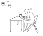
- the fatigue estimation system 200 estimates the degree of fatigue in the subject 11 by using the image output by the imaging of the subject 11 using the imaging device 201. It is a system to do.
- the image pickup device 201 is not limited in its form as long as it is a camera that captures the subject 11 and outputs an image, and is a fixed camera installed on a wall surface or ceiling of a building or the like as shown in FIG. 1A. It may be a camera mounted on a PC, a smartphone, a tablet terminal, or the like operated by the target person 11.
- the subject is in a posture of sitting on a chair 12.
- the degree of fatigue of the subject 11 is estimated based on the fatigue accumulated by taking a stationary posture in which the posture is fixed among the fatigues of the subject 11. This means that the posture is fixed, and the load on at least one of the muscles and joints and the fatigue accumulated by the worsening blood flow (hereinafter, also referred to as the decrease in blood flow) are estimated. Therefore, the subject 11 is in a stationary posture in a sitting, lying or standing position for at least a certain period of time.
- the constant period is, for example, several tens of seconds or several seconds, which is the minimum period during which fatigue can be estimated by the fatigue estimation system 200. Such a period is determined depending on the processing capacity of the image pickup apparatus 201 and the estimation apparatus 100 (see FIG. 2 described later) constituting the fatigue estimation system 200.
- Examples of the target person 11 who takes such a stationary posture include a desk worker in an office, a driver who steers a moving body, a person who performs strength training using a load in the stationary posture, a resident of a facility such as a hospital, an airplane, and the like. Passengers and crew members, etc.
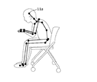
- the image captured and output by the image pickup device 201 is processed by the estimation device 100, and the posture of the subject 11 is estimated as shown in FIG. 1B.
- the estimated posture of the subject 11 is output as a rigid body link model as an example. Specifically, as shown in FIG. 1B, the skeletons shown by straight lines are connected by the joints shown by black dots, and the posture of the subject 11 can be reproduced by the positional relationship between the two skeletons connected by one joint.
- Posture estimation is performed by image recognition, and is output as the above rigid body link model based on the positional relationship between the joint and the skeleton.
- the muscles that pull the skeletons together and the body parts of the joints that connect the skeletons so that the positional relationship can be changed can be changed.
- the load applied to at least one of the muscles and joints of each body part is calculated as an estimated value. Since the estimated value of the load amount in at least one of the muscles and joints of each body part is accumulated as the duration of the resting posture is extended, the calculation using the estimated value of the load amount and the duration is used. The degree of fatigue caused by the subject 11 maintaining a stationary posture is calculated.
- “at least one of muscles and joints” is also referred to as "muscles and / or joints”.
- the degree of fatigue in addition to the above-mentioned estimated value of the load applied to the muscles and / or joints, the degree of fatigue can be estimated based on the estimated value of the blood flow rate of the subject 11.
- the degree of fatigue of the subject 11 using the estimated values of the load on the muscles and the load on the joints will be mainly described, but the estimated values of the blood flow rate are combined here. It is also possible to estimate the degree of fatigue of the subject 11 with higher accuracy. Further, the fatigue degree of the subject 11 can be estimated by using any one of the load amount to the muscle, the load amount to the joint, and the blood flow rate of the subject 11.
- the fatigue estimation system 200 estimates the posture of the subject 11, and then based on the duration of the posture, at least one of the load on the muscles, the load on the joints, and the blood flow of the subject 11. To estimate.
- the fatigue estimation system 200 estimates the degree of fatigue of the subject 11 based on at least one estimated value of the load on the muscles, the load on the joints, and the blood flow of the subject 11.
- the estimated value of the load amount may be simply expressed as the load amount or the estimated value. If the estimated value includes an estimated blood flow rate, the load amount is read as blood flow rate, and a large load amount is replaced with a decrease in blood flow rate, and a low load amount is replaced with an increase in blood flow rate. You may.
- the blood flow rate is information for quantifying the blood flow that deteriorates when the subject 11 maintains the posture, as described above.
- the blood flow rate may be acquired as an absolute numerical value at the time of measurement, or may be acquired as a relative change value of the numerical value between two different time points.
- the degree of deterioration of the blood flow of the subject 11 can be estimated from the absolute numerical values of the blood flow at the posture of the subject 11 and the start time and the end time of the posture.
- the blood flow rate of the subject is simply calculated from the posture of the elephant 11 and the duration of the posture. You may estimate.
- At least one of the load on the muscles, the load on the joints, and the blood flow is estimated from the posture of the subject 11 using the above-mentioned musculoskeletal model.
- a method using actual measurement data can also be applied as a method for estimating the load on muscles, the load on joints, and the blood flow.
- This measured data is, in other words, a database constructed by accumulating the measured values of the load on the muscles, the load on the joints, and the blood flow measured for each posture in association with the posture.
- the fatigue estimation system 200 in this case, by inputting the estimated posture of the subject 11 into the database, the measured values of the load on the muscles, the load on the joints, and the blood flow in the corresponding postures can be obtained. It can be obtained as an output.
- the measured data may be constructed using the measured values for each individual in consideration of the individual differences of the subject 11, and statistical analysis or machine learning is performed on the big data obtained from an unspecified number of subjects. It may be qualified and constructed so as to be adapted to each subject 11 by analysis processing such as.
- FIG. 2 is a block diagram showing a functional configuration of the fatigue estimation system according to the embodiment.
- the fatigue estimation system 200 in the present disclosure includes an estimation device 100, an image pickup device 201, a timekeeping device 202, a pressure sensor 203, a reception device 204, a display device 205, and a recovery device 206.
- the estimation device 100 includes a first acquisition unit 101, a second acquisition unit 102, a third acquisition unit 103, a fourth acquisition unit 104, a posture estimation unit 105, a first calculation unit 106, and a second calculation unit. It includes 107, a fatigue estimation unit 108, and an output unit 109.
- the first acquisition unit 101 is a communication module that is connected to the image pickup device 201 and acquires an image captured by the subject 11 from the image pickup device 201. That is, the first acquisition unit 101 is an example of the acquisition unit.
- the connection between the first acquisition unit 101 and the image pickup apparatus 201 is performed by wire or wirelessly, and the communication method performed via the connection is not particularly limited.
- the second acquisition unit 102 is a communication module that is connected to the timekeeping device 202 and acquires time from the timekeeping device 202.
- the connection between the second acquisition unit 102 and the timekeeping device 202 is performed by wire or wirelessly, and the method of communication performed via the connection is not particularly limited.
- the third acquisition unit 103 is a communication module connected to the pressure sensor 203 and acquires the pressure distribution from the pressure sensor 203.
- the connection between the third acquisition unit 103 and the pressure sensor 203 is performed by wire or wirelessly, and the communication method performed via the connection is not particularly limited.
- the fourth acquisition unit 104 is a communication module that is connected to the reception device 204 and acquires personal information from the reception device 204.
- the connection between the fourth acquisition unit 104 and the reception device 204 is performed by wire or wirelessly, and the communication method performed via the connection is not particularly limited.
- the posture estimation unit 105 is a processing unit realized by executing a predetermined program using a processor and a memory. By the processing of the posture estimation unit 105, the posture of the subject 11 is estimated based on the image acquired by the first acquisition unit 101 and the pressure distribution acquired by the third acquisition unit 103.
- the first calculation unit 106 is a processing unit realized by executing a predetermined program using a processor and a memory. By the processing of the first calculation unit 106, the load amount applied to each muscle and / or joint is calculated based on the estimated posture of the subject 11 and the personal information acquired by the fourth acquisition unit 104.
- the second calculation unit 107 is a processing unit realized by executing a predetermined program using a processor and a memory. By the processing of the second calculation unit 107, the amount of recovery from fatigue in individual muscles and / or joints is calculated based on the estimated amount of change in the posture of the subject.
- the fatigue estimation unit 108 is a processing unit realized by executing a predetermined program using a processor and a memory.
- the fatigue estimation unit 108 uses the posture estimated by the posture estimation unit 105 and the time acquired by the second acquisition unit 102 to determine the degree of fatigue of the subject 11 based on the estimated duration of the posture. presume.
- the output unit 109 is a communication module that is connected to the display device 205 and the recovery device 206 and outputs the contents based on the estimation result of the degree of fatigue by the estimation device 100 to the display device 205 and the recovery device 206.
- the connection between the output unit 109 and the display device 205 or the recovery device 206 is performed by wire or wirelessly, and the communication method performed via the connection is not particularly limited.
- the image pickup device 201 is a device that captures the subject 11 and outputs an image, and is realized by a camera.
- an existing camera may be used in a space to which the fatigue estimation system 200 such as a security camera or a fixed point camera is applied, or a dedicated camera may be newly provided.
- Such an image pickup device 201 is an example of an information output device that outputs an image as information regarding the position of a body part of the subject 11. Therefore, the output information is an image, and is information including the positional relationship of the body part of the subject 11 on the projected image sensor.
- the timekeeping device 202 is a device that measures time and is realized by a clock.
- the timekeeping device 202 can transmit the time to the connected second acquisition unit 102.
- the time measured by the time measuring device 202 may be an absolute time or may be a relative elapsed time from the starting point on the time axis.
- the timekeeping device 202 can be realized in any form as long as it can measure the time between two time points (that is, the duration of the stationary posture) between the time point when the subject 11 is detected to be stationary and the time point when the fatigue degree is estimated. Good.
- the pressure sensor 203 is a sensor having a detection surface, and measures the pressure applied to each of the unit detection surfaces that divide the detection surface into one or more.
- the pressure sensor 203 measures the pressure for each unit detection surface in this way and outputs the pressure distribution on the detection surface.
- the pressure sensor 203 is provided so that the subject 11 is located on the detection surface.
- the pressure sensor 203 is provided on the seat surface of the chair on which the subject 11 sits and on the backrest. Further, for example, the pressure sensor 203 may have a marker attached on the detection surface and guide the target person 11 onto the detection surface by displaying a message such as "Please sit on the marker". Further, by guiding the target person 11 on the detection surface of the pressure sensor 203 provided on a part of the floor in this way, the pressure sensor 203 can output the pressure distribution of the target person 11 on the floor. Good. Since the pressure distribution is used for the purpose of improving the estimation accuracy of the degree of fatigue, the fatigue estimation system 200 may be realized without the pressure sensor 203 if sufficient accuracy is ensured.
- the reception device 204 is a user interface that receives input of personal information of the target person 11, and is realized by an input device such as a touch panel or a keyboard.
- Personal information includes at least one of age, gender, height, weight, muscle mass, stress level, body fat percentage, and exercise proficiency.
- the age of the subject 11 may be a specific numerical value, may be an age range divided by 10 years, such as teens, 20s, and 30s, and may be 59 years or younger or 60 years or less. It may be in two age zones with a predetermined age as a boundary, such as over the age, or it may be in the other.
- the gender of the subject 11 is one that is appropriate for the subject 11, which is selected from two, male or female. Further, as the height and weight, specific values of height and weight of the subject 11 are accepted, respectively. As the muscle mass, the muscle composition ratio of the subject 11 measured using a body composition analyzer or the like is accepted. Further, the stress level of the subject 11 is selected by the subject 11 itself from options such as high, medium, and low as the degree of subjective stress felt by the subject 11.
- the body fat percentage of the subject 11 is the ratio of the weight of the body fat to the body weight of the subject 11, and is expressed by, for example, a percentage.
- the proficiency level of the subject 11 for exercise may be quantified by the score when the subject 11 executes a predetermined exercise program, or may be the situation of the exercise that the subject 11 usually works on. In the former, for example, it is quantified by the time required to perform the back muscle 10 times, the time required to run 50 m, the flight distance of long-distance casting, and the like. In the latter, for example, it is quantified by how many days of exercise or how many hours of exercise are performed in a week. Since personal information is used for the purpose of improving the accuracy of estimating the degree of fatigue, the fatigue estimation system 200 may be realized without the reception device 204 if sufficient accuracy is ensured.
- the display device 205 is a device for displaying the contents based on the estimation result of the degree of fatigue output by the output unit 109.
- the display device 205 displays an image showing the contents based on the estimation result of the degree of fatigue by a display panel such as a liquid crystal panel or an organic EL (Electroluminescence) panel.
- a display panel such as a liquid crystal panel or an organic EL (Electroluminescence) panel.
- the contents displayed by the display device 205 will be described later. Further, when the fatigue estimation system 200 is configured to only reduce the fatigue degree of the subject 11 by using the recovery device 206, it is sufficient to include only the recovery device 206, and the display device 205 is not essential.
- the recovery device 206 is a device that reduces the degree of fatigue of the subject 11 by promoting the blood circulation of the subject 11.
- the recovery device 206 is an object to be seated by applying a voltage, pressurizing, vibrating, heating, or the like, or by changing the arrangement of each part of the chair 12 by a mechanism provided in the chair 12. Actively change the posture of person 11.
- the recovery device 206 changes the mode of loading of at least one of the muscles and joints of the subject 11 and also promotes blood circulation. From the viewpoint of blood flow, by promoting blood circulation in this way, the influence of deterioration of blood flow due to the subject 11 being in a resting posture is reduced, and the degree of fatigue is recovered.
- the recovery device 206 is pre-mounted or contacted with an appropriate body part of the subject 11 depending on the configuration of the device.
- the fatigue estimation system 200 is configured to only display the estimation result of the degree of fatigue to the subject 11, only the display device 205 may be provided, and the recovery device 206 is not essential.
- FIG. 3 is a flowchart showing a method of estimating the degree of fatigue according to the embodiment.
- the fatigue estimation system 200 first acquires the personal information of the target person 11 (step S101).
- the acquisition of personal information is performed by the target person 11 himself or the manager who manages the degree of fatigue of the target person 11 by inputting to the reception device 204.
- the input personal information of the subject 11 is stored in a storage device or the like (not shown), and is read out and used when estimating the degree of fatigue.
- the fatigue estimation system 200 detects the subject 11 by the imaging device 201 (step S102).
- the detection of the target person 11 is performed by determining whether or not the target person 11 has entered the angle of view of the camera which is the imaging device 201.
- the target person 11 may be a specific target person 11, and a person who enters the angle of view of the camera from an unspecified number may be the target person 11.
- the input of personal information may be omitted.
- a step of identifying the target person 11 by image recognition or the like is added.
- the degree of fatigue is estimated by the 11 target persons inputting personal information, grasping the detection area by the imaging device 201, and entering the detection area. Therefore, image recognition or the like is unnecessary, and the degree of fatigue is estimated by taking into account personal information.
- the fatigue estimation system 200 repeats step S102 until the target person 11 is detected.
- the image output by the image pickup apparatus 201 is acquired by the first acquisition unit 101 (step S103, an example of the acquisition step).
- the estimation device 100 estimates the posture of the target person 11. Specifically, first, the third acquisition unit 103 acquires the pressure distribution applied to the detection surface from the pressure sensor 203 (step S105).
- the posture estimation unit 105 estimates the posture of the subject 11 based on the acquired image and the pressure distribution (posture estimation step S106).
- the pressure distribution is used, for example, to correct the estimated posture so that the bias is formed when a biased pressure is applied.
- the first calculation unit 106 calculates the load amount in each muscle and / or joint of the subject 11 from the estimation result of the posture. At this time, the load amount is corrected and calculated using the personal information acquired in advance (step S107). Since the posture of the subject 11 is estimated using FIG. 1B and the load amount is calculated using FIG. 1C, a specific description thereof will be omitted.
- the load amount is reduced as the age of the subject 11 is closer to the peak age of muscle development, and the load amount is increased as the distance from the peak age is increased.
- a peak value may be based on the gender of the subject 11. Further, if the gender of the subject 11 is male, the load amount may be small, and if the gender is female, the load amount may be large. Further, the smaller the height and weight of the subject 11, the smaller the load amount, and the larger the height and weight, the larger the load amount.
- the load amount may be smaller as the muscle mass of the subject 11 is larger, and the load amount may be larger as the muscle mass is smaller.
- the higher the proficiency level for exercise of the subject 11, the smaller the load amount, and the lower the proficiency level for exercise, the larger the load amount may be.
- the duration of the stationary posture of the subject 11 is measured based on the time acquired by the second acquisition unit 102 (step S108).
- the fatigue estimation unit 108 adds the load amount calculated above every time the duration elapses for a unit time, and estimates the fatigue degree of the subject 11 at this time point (fatigue estimation step S109).
- the processing of step S108 and fatigue estimation step S109 is continued until the stationary state of the subject 11 is released. Specifically, it is determined whether or not the stationary state is released depending on whether or not the posture estimated by the posture estimating unit 105 has been changed from a certain stationary posture (step S110).
- step S110 If it is not determined that the stationary state has been released (No in step S110), the process returns to step S108, the duration is measured, the process proceeds to the fatigue estimation step S109, and the load amount is added, so that the stationary posture is continued.
- the degree of fatigue of the subject 11 is integrated. That is, by repeating step S108 and fatigue estimation step S109, the fatigue estimation unit 108 fatigues the subject 11 by using an increase function of the fatigue degree having a slope corresponding to the calculated load amount with respect to the duration. Estimate the degree. Therefore, the larger the calculated load amount, the greater the degree of fatigue of the subject 11, which increases per unit time. In such integration of fatigue, the fatigue of the subject 11 is initialized (set to 0) at the start timing of the stationary posture, which is the starting point.
- the posture estimation unit 105 calculates the amount of change in the posture from the original posture in the stationary state to the changed current posture.
- the amount of change in posture is calculated for each individual muscle and / or joint in the same manner as the amount of load described above.
- the second calculation unit 107 calculates the amount of recovery, which is the degree of recovery of the degree of fatigue, based on the amount of change in posture (step S111).
- the change time which is the time during which the posture change of the subject 11 continues, is measured (step S112).
- the relationship between the recovery amount and the change time is the same as the relationship between the load amount and the duration, and the recovery amount of the subject 11 is integrated as long as the change in posture is continued. That is, the fatigue estimation unit 108 estimates the degree of fatigue of the subject 11 by subtracting the recovery amount each time a unit time elapses at the timing when the posture of the subject 11 changes in this way (step S113).
- steps S111, S112 and S113 are continued until the posture of the subject 11 is stopped. Specifically, it is determined whether or not the posture estimated by the posture estimation unit 105 is a certain stationary posture (step S114). If the stationary subject 11 is not detected (No in step S114), the process returns to step S111, the recovery amount is calculated, the process proceeds to step S112, the change time is measured, the process proceeds to step S113, and the recovery amount is subtracted. Then, as long as the posture change is continued, the degree of fatigue of the subject 11 is accumulated so as to recover.
- the fatigue estimation unit 108 uses a fatigue degree reduction function having a slope corresponding to the calculated recovery amount with respect to the change time, and the subject 11 Estimate the degree of fatigue. Since the amount of recovery of the degree of fatigue depends on the amount of change in posture, the larger the amount of change in posture, the greater the degree of fatigue of the subject 11 who decreases per unit time.
- step S114 when the subject 11 is detected to be stationary (Yes in step S114), the process returns to step S105, and the posture and the degree of fatigue are estimated again for the new stationary posture.
- the degree of fatigue of the subject 11 is calculated based on the image in consideration of the duration in the stationary posture, so that the burden on the subject 11 is small and the accuracy is higher. The degree of fatigue of the subject 11 can be estimated.
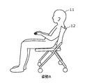
- FIG. 4A is a diagram showing a subject who is stationary in the posture A.
- FIG. 4B is a diagram showing a subject who is stationary in the posture B.
- the subject 11 shown in FIGS. 4A and 4B is in a stationary posture while sitting on the chair 12, similar to that shown in FIG. 1A.
- FIG. 4A and FIG. 4B although a table, a PC, etc. (not shown) actually exist, only the subject 11 and the chair 12 are shown here.
- the stationary posture of the subject 11 shown in FIG. 4A is a posture A in which the load on the shoulder is relatively large.
- the stationary posture of the subject 11 shown in FIG. 4B is the posture B in which the load on the shoulder is relatively small.
- FIG. 5A is a diagram illustrating the accumulation of the estimated degree of fatigue of the subject according to the embodiment.
- FIG. 5B is a second diagram illustrating the accumulation of the estimated degree of fatigue of the subject according to the embodiment.
- the fatigue degree of the subject 11 is the load amount calculated from the posture. It is represented by a linear function that is the slope.
- the posture A is a posture in which the load is larger than that of the posture B. Therefore, for example, in a certain muscle of the subject 11 (here, the muscle related to the movement of the shoulder), the load amount of the posture A (the slope of the straight line of the posture A) is larger than the load amount of the posture B (the slope of the straight line of the posture B). Is also big. Therefore, in the posture A, the subject 11 accumulates (accumulates) a larger degree of fatigue in a shorter time than when the subject 11 is stationary in the posture B.
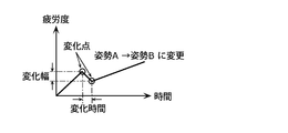
- the degree of fatigue of the subject 11 is the load amount calculated from the posture. It is expressed by a function in which a linear function whose inclination is and a linear function whose inclination is the amount of change in posture are concatenated.
- the degree of fatigue of the subject 11 is an increasing function of a positive inclination corresponding to the load amount of the posture A, as in FIG. 5A. It is estimated as the accumulation (addition) of the degree of fatigue, and the accumulation (addition) turns to recovery (decrease) at the change point where the subject 11 begins to change his / her posture.
- the fatigue level of the subject 11 is the fatigue level of the subject 11 during the period in which the posture change indicated as the change time in the figure is continued by the decrease function of the negative slope corresponding to the change amount of the posture. It recovers (decreases) by the amount shown as the range of change.
- the fatigue degree of the subject 11 is estimated as the accumulation (addition) of the fatigue degree by the increasing function of the positive slope corresponding to the load amount of the posture B. Will be done.
- the degree of fatigue of the subject 11 in which the accumulation and recovery are reflected according to the stationary and the change of the posture of the subject 11 is estimated.
- FIG. 6 is a first diagram showing a display example of the estimation result according to the embodiment.
- FIG. 7 is a second diagram showing a display example of the estimation result according to the embodiment.
- the estimation result of the fatigue degree of the subject 11 can be displayed and fed back by using the display device 205.
- the display device 205 by visualizing the degree of fatigue of the subject 11, it is possible to visually grasp how tired the subject 11 is.
- the doll imitating the subject 11 and the degree of fatigue of the shoulder, back, and main part of the subject 11 are integrally displayed by the display device 205.
- the degree of fatigue of the shoulder is shown as "stiff shoulder”
- the degree of fatigue of the back is shown as "back pain”
- the degree of fatigue of the lower back is shown as "back pain”. Has been done.
- the estimation device 100 has muscles and / or joints in each of a plurality of body parts including the first part (for example, shoulder part) and second part (for example, back part), and the third part (for example, lumbar part) of the subject 11.
- the degree of fatigue is estimated from one posture of the subject 11. Therefore, even if the posture of the subject 11 is constant, the degree of fatigue accumulated in the muscles and / or joints differs depending on the body part, but in the fatigue estimation system 200, such different degrees of fatigue are simultaneously and individually. Can be estimated.
- the load amount is calculated for each muscle and / or joint of the subject 11, so that each muscle and / or joint is not limited unless the processing resource is limited. Fatigue can be estimated. Therefore, the number of body parts whose degree of fatigue is estimated from the images captured at one time is not limited, and may be one place, two places, or four or more places.
- the estimation device 100 calculates the load amount for each of the plurality of body parts, and in one posture of the subject 11, the degree of fatigue of the first part (the above-mentioned stiff shoulder degree) due to the load amount calculated for the first part. , The fatigue degree of the second part (the above-mentioned back pain degree) due to the load amount calculated in the second part, and the fatigue degree of the third part (the above-mentioned back pain degree) due to the load amount calculated in the third part. Can be estimated.
- the stiff shoulder is estimated from the load of the trapezius muscle
- the back pain is estimated from the fatigue of the latissimus dorsi muscle
- the back pain is estimated from the load of the lumbar paraspinal muscle.
- one fatigue level may be estimated from the load amount of one muscle and / or joint, but one fatigue level may be estimated from the combined load amount of a plurality of muscles and / or joints.
- the degree of stiff shoulder (that is, the degree of fatigue of one shoulder) may be estimated from the average value of the load amounts of the trapezius muscle, the levator scapula muscle, the rhomboid muscle, and the deltoid muscle.
- the degree of fatigue estimated in this way may be shown as a relative position on a reference meter with a minimum value of 0 and a maximum value of 100, respectively, as shown in the figure.
- a reference value is provided at a predetermined position on the reference meter.
- Such a reference value is set at a relative position (or before or after) of the degree of fatigue at which subjective symptoms such as pain can occur in a general subject 11 quantified in advance by an epidemiological survey or the like. Therefore, the reference value may be set to a different value according to the degree of fatigue of each body part.
- the display device 205 may display a warning to the subject 11 as an estimation result when the estimated fatigue level of the subject 11 reaches the reference value.
- the reference value here is an example of the first threshold value.
- "the degree of stiff shoulder exceeds the reference value” is shown as displayed at the bottom of the display device 205.
- the display device 205 may display a specific coping method such as "Recommend a break" as shown in the figure.
- the display device 205 refers to the currently estimated subject 11 with respect to the subject 11 when the estimated fatigue level of the subject 11 reaches the reference value.
- a recommended posture may be displayed in which the amount of load on the body part that has reached the reference value is smaller than that of the posture.
- the reference value here is an example of the second threshold value, and may be the same as or different from the first threshold value.
- specific precautions such as "put your weight on the backrest of the chair” and "sit deeply on the seat surface” may be written together with the doll taking the posture.
- the fatigue estimation system 200 actively activates the subject 11. It is also possible to consider a configuration that recovers the degree of fatigue. Specifically, the fatigue level of the subject 11 is recovered by operating the recovery device 206 shown in FIG. The specific configuration of the recovery device 206 will be omitted because it is as described above, but when the estimated fatigue level of the subject 11 reaches the reference value, the recovery device 206 operates. By changing the load on at least one of the muscles and joints of the subject 11 and promoting blood circulation, the degree of fatigue of the subject is reduced.
- the reference value here is an example of the third threshold value, and may be the same as or different from either the first threshold value or the second threshold value.
- the fatigue estimation system 200 has an information output device (for example, an image pickup device 201) that outputs information regarding the position of a body part of the subject 11, and information output by the information output device. It is provided with an estimation device 100 that estimates the posture of the subject 11 based on (for example, an image) and estimates the degree of fatigue of the subject 11 based on the estimated posture and the duration of the posture.
- an information output device for example, an image pickup device 201 that outputs information regarding the position of a body part of the subject 11, and information output by the information output device.
- an estimation device 100 that estimates the posture of the subject 11 based on (for example, an image) and estimates the degree of fatigue of the subject 11 based on the estimated posture and the duration of the posture.
- the information output device is an image pickup device 201 that captures an image of the subject 11 and outputs an image as information regarding the position of a body part
- the estimation device 100 is based on the image output by the image pickup device 201.
- the posture of the subject 11 may be estimated.
- Such a fatigue estimation system 200 can estimate the degree of fatigue of the subject 11 using the image output by the image pickup apparatus 201.
- the posture of the subject 11 estimated from the output image is used. Specifically, the amount of load on the muscles, the amount of load on the joints, and the deterioration of blood flow due to the maintenance of a constant stationary posture from the duration elapsed in the stationary posture of the subject 11 The accumulation of fatigue associated with such factors is quantified as the degree of fatigue.
- the fatigue degree of the subject 11 is calculated based on the image in consideration of the duration in the stationary posture, so that the burden on the subject 11 is small and the accuracy is higher.
- the degree of fatigue of the subject 11 in a stationary posture can be estimated.
- the estimation device 100 calculates the load amount on at least one of the muscles and joints of the subject 11 used for maintaining the estimated posture by using a musculoskeletal model, and is a function of increasing the degree of fatigue with respect to the duration.
- the increasing function used to estimate the degree of fatigue the greater the calculated load, the greater the degree of fatigue that increases per unit time.
- the load amount for at least one of individual muscles and joints is calculated using the musculoskeletal model.
- the degree of fatigue of the subject 11 can be easily estimated by the increasing function with the load amount calculated in this way as the slope. Therefore, it is possible to easily estimate the degree of fatigue of the subject 11 with higher accuracy.
- the estimation device 100 calculates the load amount on at least one of the muscles and joints in each of two or more body parts including the first part and the second part of the body parts of the subject 11, and the subject. In one posture of 11, at least the first fatigue degree of the first part based on the load amount calculated in the first part and the second fatigue degree of the second part based on the load amount calculated in the second part. You may estimate.
- the estimation device 100 estimates the fatigue degree by using the fatigue degree decrease function with respect to time, and the decrease function used for estimating the fatigue degree has a large amount of change in the posture.
- the degree of fatigue that decreases per unit time may be increased.
- the recovery of the fatigue level by changing the load on at least one of the muscles and joints and improving the blood flow with the change in the posture of the subject 11 is reflected in the estimated fatigue level. Will be done. Therefore, the degree of fatigue of the subject 11 can be estimated with higher accuracy.
- the fatigue estimation system 200 is a display device that displays a warning to the subject 11 as an estimation result when the fatigue degree of the subject 11 estimated by the estimation device 100 reaches the first threshold value. 205 may be provided.
- the subject 11 and the like can know from the warning displayed on the display device 205 that the fatigue level of the subject 11 has reached the first threshold value.
- the subject 11 can suppress the possibility of causing poor physical condition, injury, accident, or the like due to fatigue. Therefore, the fatigue caused by the fatigue of the subject 11 is suppressed by using the fatigue degree estimated with higher accuracy.
- the fatigue estimation system 200 when the fatigue degree of the subject 11 estimated by the estimation device 100 reaches the second threshold value, the load amount on the subject 11 is more than the posture.
- a display device 205 that displays a small number of recommended postures may be provided.
- the subject 11 and the like can deal with the degree of fatigue of the subject 11 who has reached the second threshold value by the recommended posture displayed on the display device 205.
- the fatigue level of the subject 11 is expected to recover, so that the subject 11 can suppress the accumulation of fatigue without being particularly conscious of it. Therefore, the fatigue caused by the fatigue of the subject 11 is suppressed by using the fatigue degree estimated with higher accuracy.
- the fatigue estimation system 200 further promotes the blood circulation of the subject 11 when the fatigue degree of the subject 11 estimated by the estimation device 100 reaches the third threshold value.
- the recovery device 206 may be provided to reduce the degree of fatigue.
- the recovery device 206 since the recovery device 206 is expected to recover the fatigue level of the subject 11, the subject 11 can suppress the accumulation of fatigue without being particularly conscious of it. Therefore, the fatigue caused by the fatigue of the subject 11 is suppressed by using the fatigue degree estimated with higher accuracy.
- the fatigue estimation system 200 further includes a pressure sensor 203 that outputs a pressure distribution indicating the distribution of pressure applied on the detection surface, and the estimation device 100 sets the pressure distribution output by the pressure sensor 203. Based on this, the estimated posture of the subject 11 may be corrected, and the load amount for maintaining the corrected posture may be calculated.
- the pressure distribution output by the pressure sensor 203 can be used to estimate the posture of the subject 11. Therefore, the posture of the subject 11 is estimated with high accuracy by the correction in the pressure distribution. Therefore, the degree of fatigue of the subject 11 can be estimated with higher accuracy.
- the fatigue estimation system 200 further includes personal information including at least one of the age, sex, height, weight, muscle mass, stress level, body fat percentage, and exercise proficiency level of the subject 11.
- the reception device 204 is provided with an input receiving device 204, and the estimation device 100 may correct the load amount based on the personal information received by the reception device 204 when calculating the load amount for maintaining the estimated posture. Good.
- the personal information received by the reception device 204 can be used for calculating the load amount. Therefore, the load amount in the stationary posture is calculated with high accuracy by the correction with the personal information. Therefore, the degree of fatigue of the subject 11 can be estimated with higher accuracy.
- the estimation device 100 in the present embodiment is based on the first acquisition unit 101 that acquires information on the position of the body part of the subject 11 and the information acquired by the first acquisition unit 101. It includes a posture estimation unit 105 that estimates a posture, and a fatigue estimation unit 108 that estimates a degree of fatigue based on the duration of the posture estimated by the posture estimation unit 105.
- Such an estimation device 100 can estimate the degree of fatigue of the subject 11 by using the acquired information such as an image.
- the posture of the subject 11 estimated from the acquired image or the like is used. Specifically, the load on at least one of the muscles and joints and the deterioration of blood flow due to the maintenance of a constant stationary posture from the duration elapsed in the stationary posture of the subject 11 The accumulation of fatigue associated with this is quantified as the degree of fatigue.
- the fatigue degree of the subject 11 is calculated in consideration of the duration in the stationary posture, so that the fatigue degree of the subject 11 in the stationary posture can be estimated with higher accuracy. it can.
- the posture of the subject 11 is based on the acquisition step (step S103 and the like) for acquiring the information regarding the position of the body part of the subject 11 and the information acquired in the acquisition step.
- the posture estimation step S106 for estimating the fatigue degree and the fatigue estimation step S109 for estimating the degree of fatigue based on the duration of the posture estimated in the posture estimation step S106 are included.
- another processing unit may execute the processing executed by the specific processing unit.
- the order of the plurality of processes may be changed, or the plurality of processes may be executed in parallel.
- the fatigue estimation system or the estimation device in the present disclosure may be realized by a plurality of devices having a part of each of the plurality of components, or may be realized by a single device having all of the plurality of components. Good.
- a part of the function of the component may be realized as a function of another component, and each function may be distributed to each component in any way. It is included in the present disclosure if it has a configuration having substantially all the functions that can realize the fatigue estimation system or the estimation device of the present disclosure.
- each component may be realized by executing a software program suitable for each component.
- Each component may be realized by a program execution unit such as a CPU or a processor reading and executing a software program recorded on a recording medium such as a hard disk or a semiconductor memory.
- each component may be realized by hardware.
- each component may be a circuit (or an integrated circuit). These circuits may form one circuit as a whole, or may be separate circuits from each other. Further, each of these circuits may be a general-purpose circuit or a dedicated circuit.
- the general or specific aspects of the present disclosure may be realized by a recording medium such as a system, an apparatus, a method, an integrated circuit, a computer program, or a computer-readable CD-ROM. Further, it may be realized by any combination of a system, an apparatus, a method, an integrated circuit, a computer program and a recording medium.
- the posture of the target person is estimated from the image using the rigid body link model generated by image recognition, the load amount is calculated from the estimated posture of the target person, and the load amount is based on the load amount and the duration.
- the method of estimating the degree of fatigue is not limited to this. Any existing method may be used as a method of estimating the posture of the subject from the image, and any existing method may be used as a method of estimating the load amount from the posture of the subject.
- FIG. 8 is a diagram for explaining the estimation of the posture according to the modified example of the embodiment.
- the posture of the subject 11 is estimated using the sensor module 207 including the position sensor 207a and the potential sensor 207b.
- a plurality of sensor modules 207 are mounted on the target person 11, but the number of sensor modules 207 mounted on the target person 11 is not particularly limited. Only one sensor module 207 may be attached to the subject 11.
- the mounting style of the sensor module 207 is not particularly limited, and any style may be used as long as the position of a predetermined body part of the subject 11 can be measured.
- the plurality of sensor modules 207 are attached to the subject 11 by wearing a costume to which a plurality of sensor modules 207 are attached.
- the sensor module 207 is a device that is attached to a predetermined body part of the subject 11 and outputs information indicating the result of detection or measurement in conjunction with the predetermined body part. Specifically, the sensor module 207 outputs the position sensor 207a that outputs the position information regarding the spatial position of the predetermined body part of the subject 11, and the potential information indicating the potential of the target person 11 in the predetermined body part. It has a potential sensor 207b. In the figure, the sensor module 207 having both the position sensor 207a and the potential sensor 207b is shown, but if the sensor module 207 has the position sensor 207a, the potential sensor 207b is not essential.
- the position sensor 207a in such a sensor module 207 is an example of an information output device that outputs position information as information regarding the position of a body part of the subject 11. Therefore, the output information is position information, and is information including the relative or absolute position of a predetermined body part of the subject 11. Further, the output information may include, for example, potential information.
- the electric potential information is information including the electric potential value measured in a predetermined body part of the subject 11. The position information and the potential information will be described in detail below together with the position sensor 207a and the potential sensor 207b.
- the position sensor 207a detects the spatial relative position or the absolute position of the predetermined body part of the subject 11 to which the sensor module 207 is mounted, and outputs the information regarding the spatial position of the predetermined body part which is the detection result. It is a vessel.
- the information regarding the spatial position includes the information that can specify the position of the body part in the space as described above and the information that can specify the change in the position of the body part due to the body movement.
- the information regarding the spatial position includes the position of the joint and the skeleton in the space and the information indicating the change of the position.
- the position sensor 207a is configured by combining various sensors such as an acceleration sensor, an angular velocity sensor, a geomagnetic sensor, and a distance measuring sensor. Since the position information output by the position sensor 207a can be approximated to the spatial position of the predetermined body part of the subject 11, the posture of the subject 11 can be estimated from the spatial position of the predetermined body part.
- the potential sensor 207b is a detector that measures the potential of the subject 11 to which the sensor module 207 is mounted and outputs information indicating the potential of the predetermined body part, which is the measurement result.
- the potential sensor 207b is a measuring instrument having a plurality of electrodes and measuring the potential generated between the plurality of electrodes with an electrometer.
- the potential information output by the potential sensor 207b indicates the potential generated in the predetermined body part of the subject 11, and since the potential corresponds to the action potential of the muscle in the predetermined body part, the potential of the predetermined body part It is possible to improve the estimation accuracy of the posture of the subject 11 estimated from the action potential and the like.
- the fatigue estimation system in this modified example estimates the degree of fatigue of the subject 11 using the posture of the subject 11 estimated as described above. Since the processing after the estimation of the posture of the target person 11 is the same as that of the above embodiment, the description thereof will be omitted.
- the information output device is attached to a predetermined body part of the subject 11, and position information regarding the spatial position of the predetermined body part is provided as information regarding the position of the body part of the subject 11.
- the position sensor 207a outputs, and the estimation device 100 estimates the posture of the target person 11 based on the position information output by the position sensor 207a.
- the degree of fatigue of the subject 11 can be estimated using the position information output by the position sensor 207a.
- the posture of the subject 11 estimated from the output information is used. Specifically, the accumulation of fatigue due to the maintenance of a constant stationary posture is quantified as the degree of fatigue from the duration elapsed in the stationary posture of the subject 11.
- the degree of fatigue of the subject 11 is calculated based on the results of detection and measurement by the sensor module 207 in consideration of the duration in the stationary posture, so that the burden on the subject 11 is increased. It is possible to estimate the degree of fatigue of the subject 11 in a stationary posture with less and more accuracy.
- the increasing function and the decreasing function have been described as being linear linear functions, but the present invention is not limited to this.
- the increasing function may be a curvilinear function as long as the fatigue level increases with the passage of time.
- the decreasing function may be a curvilinear function as long as the fatigue degree decreases with the passage of time.
- the estimation device described above estimates the degree of fatigue of the subject using the estimated values of the load on the muscles, the load on the joints, and the blood flow rate estimated from the posture of the subject. As described above, it is also possible to correct the estimated value based on the value measured using the measuring device to realize a more accurate estimation of the degree of fatigue.
- the estimation device is a measurement value based on the measurement result of measuring the target person by the measurement device, and acquires the measurement value corresponding to the estimated value.
- the detection device is, for example, an electromyogram, a muscle hardness meter, a pressure gauge, a near-infrared spectrometer, etc., and obtains measured values relating to the amount of load on muscles, the amount of load on joints, and the amount of blood flow by measurement. Can be done.
- an electromyogram can estimate the movement of a muscle corresponding to the electric potential based on the electric potential measured by the electric potential measurement. That is, a value that estimates the movement of the muscle can be obtained as a measured value. Since the estimated value of muscle movement can be converted into the amount of load on the muscle, that is, the estimated value of the amount of load on the muscle can be corrected by the measured value.
- the correction here is, for example, to take the average value of the estimated value and the measured value, to select one of the estimated value and the measured value, and to set the estimated value to the correlation function between the estimated value and the measured value. Substitution, etc.
- the muscle hardness tester can estimate the hardness of the muscle from the stress when pressure is applied to the muscle. Since the value estimated for muscle hardness can be converted into the amount of load on the muscle, it can be used for correcting the estimated value in the same manner as described above.
- the pressure gauge can obtain as a measured value what kind of pressure is applied to the body part of the subject.
- Such pressure parameters can be input to the musculoskeletal model.
- the estimation accuracy of the musculoskeletal model is improved, and the estimated value estimated using the musculoskeletal model can be corrected with higher accuracy.
- the near-infrared spectrometer can obtain a measured value obtained by spectroscopically measuring the blood flow rate of the subject.
- the estimated value may be corrected by combining the blood flow rate measured by the infrared spectrometer. Further, even when the estimated value includes the blood flow rate, the measured blood flow rate may be used when the reliability of the estimated value of the blood flow rate is low.
- the fatigue factor identification system for identifying the cause of fatigue of the subject may be configured by using the fatigue estimation system described in the above embodiment.
- a body part in which fatigue is likely to accumulate (a body part having a large estimated amount that promotes various types of fatigue) is specified as a fatigue factor part in the stationary posture taken by the subject.
- the fatigue factor identification system may simply specify the fatigue factor part in one stationary posture taken by the subject, and the estimated amount at the most fatigue factor part from the plurality of stationary postures taken by the subject. Fatigue factors with many postures may be specified. Further, a recommended posture instead of the fatigue factor posture specified in this way may be presented, or a fatigue factor recovery operation using a recovery device may be performed on the fatigue factor portion in the fatigue factor posture.
- the fatigue factor identification system includes the fatigue estimation system described in the above embodiment and a storage device for storing information on the estimated fatigue level.
- a storage device is realized by using, for example, a semiconductor memory or the like, and each main storage unit or the like constituting the fatigue estimation system may be used, and a storage device that is communicatively connected to the estimation device is newly provided. May be good.
- the present disclosure may be realized as a fatigue estimation method executed by a fatigue estimation system or an estimation device.
- the present disclosure may be realized as a program for causing a computer to execute such a fatigue estimation method, or may be realized as a computer-readable non-temporary recording medium in which such a program is recorded. ..
- Target person 100 Estimator 101 First acquisition unit (acquisition unit) 105 Posture estimation unit 108 Fatigue estimation unit 200 Fatigue estimation system 201 Imaging device 203 Pressure sensor 204 Reception device 205 Display device 206 Recovery device 207a Position sensor
Landscapes
- Health & Medical Sciences (AREA)
- Life Sciences & Earth Sciences (AREA)
- Engineering & Computer Science (AREA)
- Physics & Mathematics (AREA)
- Pathology (AREA)
- Heart & Thoracic Surgery (AREA)
- Public Health (AREA)
- General Health & Medical Sciences (AREA)
- Surgery (AREA)
- Molecular Biology (AREA)
- Medical Informatics (AREA)
- Biophysics (AREA)
- Animal Behavior & Ethology (AREA)
- Biomedical Technology (AREA)
- Veterinary Medicine (AREA)
- Physiology (AREA)
- Oral & Maxillofacial Surgery (AREA)
- Dentistry (AREA)
- Social Psychology (AREA)
- Psychology (AREA)
- Psychiatry (AREA)
- Hospice & Palliative Care (AREA)
- Human Computer Interaction (AREA)
- General Physics & Mathematics (AREA)
- Multimedia (AREA)
- Theoretical Computer Science (AREA)
- Educational Technology (AREA)
- Developmental Disabilities (AREA)
- Child & Adolescent Psychology (AREA)
- Hematology (AREA)
- Cardiology (AREA)
- Computer Vision & Pattern Recognition (AREA)
- Nuclear Medicine, Radiotherapy & Molecular Imaging (AREA)
- Radiology & Medical Imaging (AREA)
- Measurement Of The Respiration, Hearing Ability, Form, And Blood Characteristics Of Living Organisms (AREA)
Abstract
疲労推定システム(200)は、対象者(11)の身体部位の位置に関する情報(画像)を出力する情報出力装置(撮像装置(201))と、情報出力装置において出力された情報に基づいて、対象者(11)の姿勢を推定し、推定した姿勢及び姿勢の継続時間に基づいて、対象者(11)の疲労度を推定する推定装置(100)と、を備える。
Description
本開示は、対象者の疲労度を推定するための疲労推定システム、当該推定システムに使用される推定装置、及び疲労推定方法に関する。
近年、疲労の蓄積から体調不良をはじめ、怪我及び事故等につながるといった事例が散見される。これに対して、疲労の程度を推定することにより、体調不良、怪我及び事故等を未然に防ぐ技術に注目されるようになった。例えば、疲労度を推定するための疲労推定システムとして、特許文献1には、力計測、及び生体電気インピーダンス計測に基づいて疲労の有無及び疲労の種類を判定する、疲労判定装置が開示されている。
ところで、上記特許文献1に例示される従来の疲労判定装置等では、推定される疲労度の精度が十分でない場合がある。そこで、本開示では、より高精度に疲労度を推定する疲労推定システム等を提供する。
本開示の一態様に係る疲労推定システムは、対象者の身体部位の位置に関する情報を出力する情報出力装置と、前記情報出力装置において出力された前記情報に基づいて、前記対象者の姿勢を推定し、推定した前記姿勢及び前記姿勢の継続時間に基づいて、前記対象者の疲労度を推定する推定装置と、を備える。
また、本開示の一態様に係る推定装置は、対象者の身体部位の位置に関する情報を取得する取得部と、前記取得部において取得された前記情報に基づいて、前記対象者の姿勢を推定する姿勢推定部と、前記姿勢推定部において推定された前記姿勢の継続時間に基づいて、前記疲労度を推定する疲労推定部と、を備える。
また、本開示の一態様に係る疲労推定方法は、対象者の身体部位の位置に関する情報を取得する取得ステップと、前記取得ステップにおいて取得された前記情報に基づいて、前記対象者の姿勢を推定する姿勢推定ステップと、前記姿勢推定ステップにおいて推定された前記姿勢の継続時間に基づいて、前記疲労度を推定する疲労推定ステップと、を含む。
本開示の一態様に係る疲労推定システム等は、より高精度に疲労を推定することができる。
以下、実施の形態について、図面を参照しながら具体的に説明する。なお、以下で説明する実施の形態は、いずれも包括的又は具体的な例を示すものである。以下の実施の形態で示される数値、形状、材料、構成要素、構成要素の配置位置及び接続形態、ステップ、ステップの順序などは、一例であり、本開示を限定する主旨ではない。また、以下の実施の形態における構成要素のうち、独立請求項に記載されていない構成要素については、任意の構成要素として説明される。
なお、各図は模式図であり、必ずしも厳密に図示されたものではない。また、各図において、実質的に同一の構成に対しては同一の符号を付し、重複する説明は省略または簡略化される場合がある。
(実施の形態)
[疲労推定システム]
以下、実施の形態に係る疲労推定システムの全体構成について説明する。図1Aは、実施の形態に係る疲労度の推定を説明するための第1図である。図1Bは、実施の形態に係る疲労度の推定を説明するための第2図である。図1Cは、実施の形態に係る疲労度の推定を説明するための第3図である。
[疲労推定システム]
以下、実施の形態に係る疲労推定システムの全体構成について説明する。図1Aは、実施の形態に係る疲労度の推定を説明するための第1図である。図1Bは、実施の形態に係る疲労度の推定を説明するための第2図である。図1Cは、実施の形態に係る疲労度の推定を説明するための第3図である。
本開示における疲労推定システム200(後述する図2参照)は、実施の形態では、撮像装置201を用いた対象者11の撮像によって出力された画像を用いて、当該対象者11における疲労度を推定するシステムである。撮像装置201は、対象者11を撮像して画像を出力するカメラであればその形態に限定はなく、図1Aに示すように、建物等の壁面又は天井等に設置される固定式のカメラであってもよく、対象者11が操作するPC、スマートフォン、又はタブレット端末等に搭載されたカメラであってもよい。
ここで対象者は、椅子12に着座した姿勢である。本開示における疲労推定システム200では、対象者11における疲労のうち、姿勢が固定された静止姿勢をとることによって蓄積する疲労をもとに対象者11の疲労度を推定する。これはつまり、姿勢が固定された状態により、筋肉及び関節の少なくとも一方における負荷ならびに悪化する血流(以下、血流量の低下ともいう)によって蓄積される疲労を推定している。したがって、対象者11は、少なくとも一定の期間において座位、臥位又は立位で静止した静止姿勢である。一定の期間とは、例えば、数十秒又は数秒等、疲労推定システム200において疲労が推定可能な最小の期間である。このような期間は、疲労推定システム200を構成する撮像装置201及び推定装置100(後述する図2参照)による処理能力に依存して決定される。
このような静止姿勢をとる対象者11としては、例えば、オフィスにおけるデスクワーカ、移動体を操舵するドライバ、静止姿勢での負荷を利用した筋力トレーニングを行う者、病院等の施設の入所者、飛行機等の乗客及び乗員等が挙げられる。
撮像装置201によって撮像され、出力された画像は、推定装置100によって処理され、図1Bに示すように対象者11の姿勢が推定される。推定された対象者11の姿勢は、一例として剛体リンクモデルとして出力される。具体的には、図1Bに示すように、直線で示す骨格が黒点で示す関節によって接続され、一つの関節によって接続される二つの骨格同士の位置関係によって、対象者11の姿勢を再現できる。姿勢の推定は、画像認識によって行われ、関節と骨格との位置関係に基づき、上記の剛体リンクモデルとして出力される。
推定された剛体リンクモデルを、図1Cに示すような筋骨格モデルに当てはめることで、骨格同士を引っ張り合う筋肉、及び、当該骨格同士の位置関係を変更可能に接続する関節の各々の身体部位について、推定された姿勢に応じた位置関係に維持するために、個々の身体部位の筋肉及び関節の少なくとも一方にかかる負荷量を推定値として算出する。この各々の身体部位の筋肉及び関節の少なくとも一方における負荷量の推定値が、上記静止姿勢が継続された継続時間が延びるほど蓄積されるため、負荷量の推定値と継続時間とを用いた演算によって対象者11が静止姿勢を維持することによる疲労度が算出される。なお、以降の説明では、「筋肉及び関節の少なくとも一方」を「筋肉及び/又は関節」とも表現する。
また、本実施の形態では、上記の筋肉及び/又は関節にかかる負荷量の推定値に加え、対象者11の血流量の推定値に基づく疲労度の推定を行うことができる。以下の説明では、筋肉への負荷量及び関節への負荷量の推定値を用いて対象者11の疲労度の推定を行う例を中心に説明するが、ここに血流量の推定値を組み合わせて対象者11の疲労度の推定をより高精度に行うことも可能である。さらに、対象者11の疲労度の推定は、対象者11の筋肉への負荷量、関節への負荷量、及び血流量のいずれか一つの推定値を用いて行うことも可能である。
すなわち、疲労推定システム200は、対象者11の姿勢を推定した後、当該姿勢の継続時間に基づいて、対象者11の筋肉への負荷量、関節への負荷量、及び血流量の少なくとも一つを推定する。疲労推定システム200は、推定した対象者11の筋肉への負荷量、関節への負荷量、及び血流量の少なくとも一つの推定値に基づいて対象者11の疲労度の推定を行う。以下、簡略化のため、負荷量の推定値を、単に負荷量又は推定値と表現する場合がある。また、推定値に血流量の推定値が含まれる場合には、負荷量を血流量と読み替え、負荷量が多いことを血流量の低下に、負荷量が少ないことを血流量の上昇にそれぞれ置き換えてもよい。
また、血流量とは、上記したように、対象者11が姿勢を維持することで悪化する血流を数値化するための情報である。血流量は、低下するほど、対象者11の血流が悪化していることを意味し、血流の悪化によって引き起こされる疲労の指標として利用できる。血流量は、測定時点における絶対的な数値として取得されてもよく、異なる2時点間での数値の相対的な変化値として取得されてもよい。例えば、対象者11の姿勢と、当該姿勢の開始時点と終了時点との2時点における血流量の絶対的数値によって、対象者11の血流の悪化の程度を推定できる。また、対象者11の姿勢及び当該姿勢の継続時間と、血流の悪化との間に相関関係が存在するため、単に、象者11の姿勢及び当該姿勢の継続時間から対象者の血流量を推定してもよい。
また、以降の説明では、上記した筋骨格モデルを用いて、対象者11の姿勢からの、筋肉への負荷量、関節への負荷量、及び血流量の少なくとも一つの推定を行うが、姿勢から、筋肉への負荷量、関節への負荷量、及び血流量を推定する方法として、上記の筋骨格モデルの他に、実測データを用いる方法を適用することも可能である。この実測データは、つまり、姿勢ごとに計測された、筋肉への負荷量、関節への負荷量、及び血流量の実測値を姿勢と対応付けて蓄積することで構築されたデータベースである。この場合の疲労推定システム200では、推定された対象者11の姿勢をデータベースに入力することで、対応する姿勢での、筋肉への負荷量、関節への負荷量、及び血流量の実測値を出力として得ることができる。
実測データは、対象者11の個人差を考慮して、個人ごとの実測値を用いて構築されてもよく、不特定多数の被検者から得られたビッグデータについて、統計解析、又は機械学習等の解析処理によって対象者11ごとに適合するよう、適格化して構築されてもよい。
次に、本開示における疲労推定システム200の機能構成について、図2を用いて説明する。図2は、実施の形態に係る疲労推定システムの機能構成を示すブロック図である。
図2に示すように、本開示における疲労推定システム200は、推定装置100、撮像装置201、計時装置202、圧力センサ203、受付装置204、表示装置205、及び回復装置206を備える。
推定装置100は、第1取得部101と、第2取得部102と、第3取得部103と、第4取得部104と、姿勢推定部105と、第1算出部106と、第2算出部107と、疲労推定部108と出力部109と、を備える。
第1取得部101は、撮像装置201に接続され、撮像装置201から対象者11が撮像された画像を取得する通信モジュールである。つまり、第1取得部101は、取得部の一例である。第1取得部101と撮像装置201との接続は、有線又は無線によって行われ、当該接続を介して行われる通信の方式にも特に限定はない。
第2取得部102は、計時装置202に接続され、計時装置202から時間を取得する通信モジュールである。第2取得部102と計時装置202との接続は、有線又は無線によって行われ、当該接続を介して行われる通信の方式にも特に限定はない。
第3取得部103は、圧力センサ203に接続され、圧力センサ203から圧力分布を取得する通信モジュールである。第3取得部103と圧力センサ203との接続は、有線又は無線によって行われ、当該接続を介して行われる通信の方式にも特に限定はない。
第4取得部104は、受付装置204に接続され、受付装置204から個人情報を取得する通信モジュールである。第4取得部104と受付装置204との接続は、有線又は無線によって行われ、当該接続を介して行われる通信の方式にも特に限定はない。
姿勢推定部105は、プロセッサ及びメモリを用いて所定のプログラムが実行されることにより実現される処理部である。姿勢推定部105の処理により、第1取得部101において取得された画像、及び第3取得部103において取得された圧力分布に基づいて、対象者11の姿勢が推定される。
第1算出部106は、プロセッサ及びメモリを用いて所定のプログラムが実行されることにより実現される処理部である。第1算出部106の処理により、推定された対象者11の姿勢、及び第4取得部104において取得された個人情報に基づいて、個々の筋肉及び/又は関節にかかる負荷量が算出される。
第2算出部107は、プロセッサ及びメモリを用いて所定のプログラムが実行されることにより実現される処理部である。第2算出部107の処理により、推定された対象者の姿勢の変化における変化量に基づいて、個々の筋肉及び/又は関節における疲労の回復量が算出される。
疲労推定部108は、プロセッサ及びメモリを用いて所定のプログラムが実行されることにより実現される処理部である。疲労推定部108は、姿勢推定部105において推定された姿勢と、第2取得部102において取得された時間とを用いて、推定された姿勢の継続時間に基づいて、対象者11の疲労度を推定する。
出力部109は、表示装置205及び回復装置206に接続され、推定装置100による疲労度の推定結果に基づく内容を表示装置205及び回復装置206に出力する通信モジュールである。出力部109と表示装置205又は回復装置206との接続は、有線又は無線によって行われ、当該接続を介して行われる通信の方式にも特に限定はない。
撮像装置201は、上記したように、対象者11を撮像して画像を出力する装置であり、カメラによって実現される。撮像装置201として、防犯カメラ、定点カメラ等の疲労推定システム200を適用する空間に既存のカメラが用いられてもよく、専用のカメラが新たに設けられてもよい。このような撮像装置201は、画像を対象者11の身体部位の位置に関する情報として出力する情報出力装置の一例である。したがって、出力される情報は、画像であり、対象者11の身体部位の、投影された撮像素子上での位置関係を含む情報である。
計時装置202は、時間を計測する装置であり、時計によって実現される。計時装置202は、接続された第2取得部102へと時間を送信可能である。ここで、計時装置202によって計測される時間とは、絶対的な時刻であってもよく、時間軸上の起点からの相対的な経過時間であってもよい。計時装置202は、対象者11の静止を検出した時点と、疲労度を推定する時点との2時点の間の時間(つまり静止姿勢の継続時間)が計測できればどのような形態で実現されてもよい。
圧力センサ203は、検出面を有するセンサであり、当該検出面を1以上に区切る単位検出面のそれぞれに付与される圧力を計測する。圧力センサ203は、このように単位検出面ごとの圧力を計測し、検出面上における圧力分布を出力する。圧力センサ203は、対象者11が検出面上に位置するように設けられる。
例えば、圧力センサ203は、対象者11が着座する椅子の座面、及びバックレストに設けられる。また、例えば、圧力センサ203は、検出面上にマーカが付され、「マーカの上に座ってください」等の表示によって、対象者11を検出面上に誘導するようにしてもよい。また、このようにして、床上の一部分に設けられた圧力センサ203の検出面上に対象者11を誘導することで、圧力センサ203は、床上での対象者11の圧力分布を出力してもよい。なお、圧力分布は、疲労度の推定精度を向上する目的で使用されるため、十分な精度が確保される場合には、圧力センサ203を備えずに疲労推定システム200を実現してもよい。
受付装置204は、対象者11の個人情報の入力を受け付けるユーザインタフェースであり、タッチパネル又はキーボード等の入力装置によって実現される。個人情報は、年齢、性別、身長、体重、筋肉量、ストレス度、体脂肪率、及び運動に対する習熟度のうち少なくとも一つを含む。対象者11の年齢は、具体的な数値であってもよく、10代、20代、及び30代のように、10歳ごとに区分された年齢帯であってもよく、59歳以下又は60歳以上のように所定の年齢を境とした二区分の年齢帯であってもよく、その他であってもよい。
また、対象者11の性別は、男性又は女性の二者のうちから選択される、対象者11に適切な一方である。また、身長及び体重としては、対象者11の具体的な身長及び体重の数値がそれぞれ受け付けられる。また、筋肉量としては、体組成計等を用いて計測された対象者11の筋肉の組成比率が受け付けられる。また、対象者11のストレス度は、対象者11が感じる主観的なストレスの程度として、高度、中度及び低度等の選択肢の中から対象者11自身によって選択される。
また、対象者11の体脂肪率は、対象者11の体重に占める体脂肪の重量の比率であり、例えば、100分率等で表現される。
また、対象者11の運動に対する習熟度は、所定の運動プログラムを対象者11が実施した際のスコアで定量化されていてもよく、対象者11が普段取り組む運動の状況であってもよい。前者では、例えば、背筋を10回行うのに要した時間、50mを走るのに要した時間、遠投の飛距離等によって定量化される。後者では、例えば、一週間に何日運動を行うか、又は何時間運動を行うか等によって定量化される。なお、個人情報は、疲労度の推定精度を向上する目的で使用されるため、十分な精度が確保される場合には、受付装置204を備えずに疲労推定システム200を実現してもよい。
表示装置205は、出力部109によって出力された、疲労度の推定結果に基づく内容を表示するための装置である。表示装置205は、例えば、液晶パネルまたは有機EL(Electro Luminescence)パネルなどの表示パネルによって、疲労度の推定結果に基づく内容を示す画像を表示する。表示装置205によって表示される内容については後述する。また、疲労推定システム200は、回復装置206を用いて対象者11の疲労度を低下させるのみの構成である場合、回復装置206のみを備えればよく、表示装置205は必須でない。
回復装置206は、対象者11の血行を促進させることで対象者11の疲労度を低下させる装置である。回復装置206は、具体的には、電圧印加、加圧、加振もしくは加温等を行う、又は、椅子12に備えられた機構により椅子12の各部の配置を変化させることで、着座する対象者11の姿勢を能動的に変更する。これにより、回復装置206は、対象者11の筋肉及び関節の少なくとも一方の負荷の態様を変更し、また、血行を促進させる。血流量の観点においても、このようにして血行が促進されることで、対象者11が静止姿勢であることによる血流悪化の影響が低減され、疲労度が回復する。回復装置206は、装置の構成に応じて、対象者11の適切な身体部位にあらかじめ装着又は接触される。
なお、加温により対象者11の血行を促進させる場合、対象者11の周囲の空間ごと加温するため、このような場合は、対象者11の適切な身体部位に装着又は接触される必要はない。また、疲労推定システム200は、対象者11に対して疲労度の推定結果を表示するのみの構成である場合、表示装置205のみを備えればよく、回復装置206は必須でない。
[動作]
次に、実施の形態における疲労推定システム200を用いた対象者11の疲労度の推定について、図3~図5Bを用いて説明する。図3は、実施の形態に係る疲労度の推定方法を示すフローチャートである。
次に、実施の形態における疲労推定システム200を用いた対象者11の疲労度の推定について、図3~図5Bを用いて説明する。図3は、実施の形態に係る疲労度の推定方法を示すフローチャートである。
疲労推定システム200は、はじめに対象者11の個人情報を取得する(ステップS101)。個人情報の取得は、受付装置204への入力によって、対象者11本人又は対象者11の疲労度を管理する管理者等によって行われる。入力された対象者11の個人情報は、図示しない記憶装置等に格納され、疲労度の推定の際に読み出されて使用される。
疲労推定システム200は、撮像装置201により対象者11の検知を行う(ステップS102)。対象者11の検知は、撮像装置201であるカメラの画角内に対象者11が入り込んだか否かの判定によって行われる。なお、このとき対象者11は、特定の対象者11であってもよく、不特定多数の中から、カメラの画角内に入った人物が対象者11となってもよい。不特定多数の中から対象者11が選択される場合、個人情報の入力が省略されてもよい。また、特定の対象者11を検知する場合には、画像認識等により対象者11を特定するステップが追加される。
本実施の形態では、対象者11本人が個人情報を入力したうえ、撮像装置201による検知エリアを把握して、当該検知エリア内に入ることで、疲労度の推定が行われる例を説明する。したがって、画像認識等は不要であり、かつ、個人情報を加味して疲労度が推定される。
疲労推定システム200は、対象者11が検知されていないと判定された場合(ステップS102でNo)、対象者11が検知されるまでステップS102を繰り返す。一方、対象者11が検知された場合(ステップS102でYes)、撮像装置201によって出力された画像が第1取得部101によって取得される(ステップS103、取得ステップの一例)。ここで、取得された画像において、対象者11が静止している(静止姿勢である)ことが検知されると(ステップS104)、推定装置100において対象者11の姿勢の推定が行われる。具体的には、まず、第3取得部103は、圧力センサ203から検出面に付与される圧力分布を取得する(ステップS105)。
姿勢推定部105は、取得された画像及び圧力分布に基づき対象者11の姿勢を推定する(姿勢推定ステップS106)。圧力分布は、例えば、偏った圧力が付与されている場合、推定される姿勢を当該偏りが形成されるように補正するために使用される。次に、第1算出部106は、姿勢の推定結果から、対象者11の個々の筋肉及び/又は関節における負荷量を算出する。このとき、あらかじめ取得した個人情報を用いて、負荷量を補正して算出する(ステップS107)。なお、対象者11の姿勢の推定は図1Bを用いて、負荷量の算出は図1Cを用いてそれぞれ説明した通りであるため、具体的な説明を省略する。
個人情報を用いた負荷量の補正では、例えば、対象者11の年齢が筋肉の発達のピーク年齢に近いほど負荷量を少なくし、当該ピーク年齢から離れるほど負荷量を多くする。このようなピーク値は対象者11の性別に基づいてもよい。また、対象者11の性別が男性であれば負荷量を少なく、女性であれば負荷量を多くしてもよい。また、対象者11の身長及び体重が小さい値であるほど負荷量を少なく、身長及び体重が大きい値であるほど負荷量を多くしてもよい。
また、対象者11の筋肉量が大きい組成比率であるほど負荷量を少なく、筋肉量が小さい組成比率であるほど負荷量を多くしてもよい。また、対象者11のストレス度が低いほど負荷量を少なく、ストレス度が高いほど負荷量を多くしてもよい。また、対象者11の体脂肪率が高いほど負荷量を多く、体脂肪率が低いほど負荷量を少なくしてもよい。さらに、対象者11の運動に対する習熟度が高いほど負荷量を少なく、運動に対する習熟度が低いほど負荷量を多くしてもよい。
ここで、第2取得部102において取得される時間をもとに、対象者11の静止姿勢の継続時間を計測する(ステップS108)。疲労推定部108は、継続時間が単位時間を経過するごとに上記で算出した負荷量を加算し、この時点における対象者11の疲労度を推定する(疲労推定ステップS109)。ステップS108及び疲労推定ステップS109の処理を、対象者11の静止状態が解除されるまで継続する。具体的に、姿勢推定部105において推定される姿勢が、ある静止姿勢から変更されたか否かにより、静止状態の解除の有無を判定する(ステップS110)。
静止状態が解除されたと判定されない場合(ステップS110でNo)、ステップS108に戻り、継続時間を計測し、疲労推定ステップS109に進み、負荷量の加算を行うことで、静止姿勢が継続される限り対象者11の疲労度を積算していく。つまり、疲労推定部108は、ステップS108及び疲労推定ステップS109を繰り返すことで、継続時間に対して、算出された負荷量に相当する傾きを有する疲労度の増加関数を用いて対象者11の疲労度を推定する。したがって、算出した負荷量が多いほど、単位時間当たりに増加する対象者11の疲労度が大きくなる。なお、このような疲労度の積算においては、起点である静止姿勢の開始タイミングで対象者11の疲労度が初期化(疲労度0に設定)される。
一方で、静止状態が解除されたと判定された場合(ステップS110でYes)、姿勢推定部105は、元の静止状態の姿勢から、変化した現時点の姿勢までの姿勢の変化量を算出する。姿勢の変化量は、上記の負荷量と同様に個々の筋肉及び/又は関節ごとに算出される。このように姿勢が変化した際、筋肉及び関節の少なくとも一方に対する負荷が変化し、また、血流量の観点では、悪化していた血流が一時的に緩和され、対象者11の疲労度は回復に転じる。回復によって低減される疲労度は、姿勢の変化量に関連する。したがって、第2算出部107は、姿勢の変化量に基づき、疲労度の回復の程度である回復量を算出する(ステップS111)。
第2取得部102において取得される時間をもとに、対象者11の姿勢の変更が継続する時間である変化時間を計測する(ステップS112)。回復量と変化時間との関係は、負荷量と継続時間との関係と同様であり、姿勢の変化が継続される限り対象者11の回復量を積算していく。つまり、疲労推定部108は、このように対象者11の姿勢が変化するタイミングでは、単位時間が経過するごとに回復量を減算することで対象者11の疲労度を推定する(ステップS113)。
ステップS111、ステップS112及びステップS113の処理を、対象者11の姿勢が静止されるまで継続する。具体的に、姿勢推定部105において推定される姿勢が、ある静止姿勢であるか否かを判定する(ステップS114)。対象者11の静止が検出されない場合(ステップS114でNo)、ステップS111に戻り、回復量を算出し、ステップS112に進み、変化時間を計測し、ステップS113に進み、回復量の減算を行うことで、姿勢の変更が継続される限り対象者11の疲労度が回復するように積算していく。
つまり、疲労推定部108は、ステップS111、ステップS112及びステップS113を繰り返すことで、変化時間に対して、算出された回復量に相当する傾きを有する疲労度の減少関数を用いて対象者11の疲労度を推定する。疲労度の回復量は、姿勢の変化量に依存しているため、姿勢の変化量が大きいほど、単位時間当たりに減少する対象者11の疲労度が大きくなる。
一方で、対象者11の静止が検出された場合(ステップS114でYes)、ステップS105に戻り、再度新たな静止姿勢について、姿勢及び疲労度の推定を行う。このようにして、疲労推定システム200では、画像に基づき静止姿勢での継続時間を考慮して対象者11の疲労度が算出されるため、対象者11の負担が少なく、かつ、より高精度に対象者11の疲労度を推定することができる。
以上に関して、さらに図4A~図5Bを用いて具体的に説明する。図4Aは、姿勢Aで静止する対象者を示す図である。また、図4Bは、姿勢Bで静止する対象者を示す図である。
図4A及び図4Bに示す対象者11は、図1Aに示したものと同様に、椅子12に着座した座位にて静止姿勢をとっている。なお、図4A及び図4Bでは、図示しないテーブルやPC等が実際には存在するが、ここでは対象者11及び椅子12のみを図示している。図4Aに示す対象者11の静止姿勢は、肩への負荷が比較的に多い姿勢Aである。一方で、図4Bに示す対象者11の静止姿勢は、肩への負荷が比較的に少ない姿勢Bである。
このような姿勢A又は姿勢Bで静止する対象者11において推定される疲労度は、図5A及び図5Bのように蓄積される。図5Aは、実施の形態に係る推定される対象者の疲労度の蓄積を説明する第1図である。また、図5Bは、実施の形態に係る推定される対象者の疲労度の蓄積を説明する第2図である。
図5Aに示すように、対象者11の姿勢が図4Aに示す姿勢A又は図4Bに示す姿勢Bのまま静止している場合、対象者11の疲労度は、姿勢から算出される負荷量を傾きとする一次関数によって表現される。
上記したように、姿勢Aは、姿勢Bに比べて負荷が大きい姿勢である。したがって、例えば、対象者11のある筋肉(ここでは肩の可動に関する筋肉)において、姿勢Aの負荷量(姿勢Aの直線の傾き)は、姿勢Bの負荷量(姿勢Bの直線の傾き)よりも大きい。このため、対象者11は、姿勢Aでは、姿勢Bで静止している場合に比べ、より短時間により多くの疲労度が蓄積(積算)されてしまう。
一方で、図5Bに示すように、対象者11の姿勢が図4Aに示す姿勢Aから図4Bに示す姿勢Bへと変化する場合、対象者11の疲労度は、姿勢から算出される負荷量を傾きとする一次関数と、姿勢の変化量を傾きとする一次関数とが連結された関数によって表現される。
したがって、例えば、対象者11のある筋肉において、姿勢Aで静止している間は、対象者11の疲労度は、図5Aと同様に、姿勢Aの負荷量に相当する正の傾きの増加関数によって疲労度の蓄積(加算)として推定され、対象者11が姿勢を変更し始めた変化点において蓄積(加算)が回復(減少)に転じる。対象者11の疲労度は、姿勢の変更量に相当する負の傾きの減少関数によって、図中に変化時間として示す姿勢の変更が継続している期間に、対象者11の疲労度が、図中に変化幅として示す量だけ回復(減少)する。対象者11の姿勢が姿勢Bで再び静止した変化点以降では、対象者11の疲労度は、姿勢Bの負荷量に相当する正の傾きの増加関数で、疲労度の蓄積(加算)として推定される。
このように、本実施の形態における疲労推定システム200では、対象者11の姿勢の静止と変更とに応じて蓄積及び回復が反映された対象者11の疲労度が推定される。
次に、推定された疲労度に基づく出力部109の出力の一例を説明する。図6は、実施の形態に係る推定結果の表示例を示す第1図である。また、図7は、実施の形態に係る推定結果の表示例を示す第2図である。
図6及び図7に示すように、疲労推定システム200では、対象者11の疲労度の推定結果を、表示装置205を用いて表示してフィードバックすることができる。具体的には、図6に示すように、対象者11の疲労度を可視化することで、視覚的に対象者11がどの程度疲労しているかを把握することができる。図中では、対象者11を模した人形と、対象者11の肩部、背部、及び要部の疲労度のそれぞれとを、表示装置205によって一体的に表示している。対象者11が直感的に疲労度を把握しやすくするため、肩部の疲労度が「肩こり度」、背部の疲労度が「背部痛度」、腰部の疲労度が「腰痛度」としてそれぞれ示されている。
ここで、図中の表示では、対象者11の3か所の疲労度が一挙に表示されているが、これら3か所の疲労度の推定は、一度に撮像された画像から行われる。つまり、推定装置100は、対象者11の第1部位(例えば肩部)及び第2部位(例えば背部)、及び第3部位(例えば腰部)を含む複数の身体部位の各々における筋肉及び/又は関節について、対象者11の一つの姿勢から疲労度を推定する。したがって、対象者11の姿勢が一定であっても、身体部位ごとに筋肉及び/又は関節に蓄積される疲労度は異なるが、疲労推定システム200では、このように異なる疲労度を同時かつ個別に推定できる。
図1Cを用いて説明したように、本実施の形態では、対象者11の筋肉及び/又は関節一つひとつについて負荷量が算出されるため、処理リソースの制限がなければ、筋肉及び/又は関節の一つひとつの疲労度を推定することができる。したがって、一度に撮像された画像から疲労度が推定される身体部位の数に限定はなく、1か所でもよく、2か所でもよく、4か所以上でもよい。
推定装置100では、複数の身体部位の各々で負荷量を算出し、対象者11の一つの姿勢において、第1部位で算出された負荷量による第1部位の疲労度(上記の肩こり度)と、第2部位で算出された負荷量による第2部位の疲労度(上記の背部痛度)と、第3部位で算出された負荷量による第3部位の疲労度(上記の腰痛度)と、を推定できる。
また、図中の例では、僧帽筋の負荷量から肩こり度が推定され、広背筋の疲労度から背部痛度が推定され、腰部傍脊柱筋の負荷量から腰痛度が推定される。このように、一つの筋肉及び/又は関節の負荷量から、一つの疲労度を推定してもよいが、複数の筋肉及び/又は関節の複合的な負荷量から、一つの疲労度を推定してもよい。例えば、僧帽筋と、肩甲挙筋と、菱形筋と、三角筋との負荷量の平均値から肩こり度(つまり肩部の一つの疲労度)が推定されてもよい。また、疲労度の推定では、単純な平均値ではなく、当該身体部位の疲労度に特に大きく影響する筋肉及び/又は関節の負荷量に重みづけすることで、より現実に即した疲労度の推定を行ってもよい。
このようにして推定された疲労度は、それぞれ図示するように最小値を0、最大値を100とする基準メータ上の相対位置として示されてもよい。ここで、基準メータ上の所定の位置に基準値が設けられる。このような基準値は、疫学的調査等によって事前に数値化された一般的な対象者11において痛みなどの自覚症状が発現し得る疲労度の相対位置(又はその前後等)に設定される。したがって、基準値は、各身体部位の疲労度に応じて異なる値が設定されてもよい。
さらに、表示装置205は、推定された対象者11の疲労度が基準値に達したことを契機に、対象者11に対する警告を推定結果として表示してもよい。ここでの基準値は、第1閾値の一例である。図中では、このような警告の一例として、表示装置205の下部に表示されているように「肩こり度が基準値を超えています。」を示している。また、このような警告に関連して、表示装置205は、図中に併記されているように「休憩をおすすめします。」等の具体的な対処方法を表示してもよい。
また、図7に示すように、表示装置205は、推定された対象者11の疲労度が基準値に達したことを契機に、対象者11に対して、現在推定されている対象者11の姿勢よりも、基準値に達した身体部位における負荷量が少ない推奨姿勢を表示してもよい。ここでの基準値は、第2閾値の一例であり、第1閾値と同一であってもよく、異なっていてもよい。表示される推奨姿勢には、当該姿勢をとる人形とともに「椅子の背もたれに体重を預ける」及び「座面に深く腰掛ける」のように、具体的な注意点が併記されてもよい。
また、以上のように、対象者11に対して推定結果を表示することで対象者11自身が蓄積される疲労度に対処することを促す構成の他、疲労推定システム200がアクティブに対象者11の疲労度を回復させる構成も考えられ得る。具体的には、図2に示した回復装置206が動作することで、対象者11の疲労度が回復される。回復装置206の具体的な構成については、上記したとおりであるので説明を省略するが、推定された対象者11の疲労度が基準値に達したことを契機に、回復装置206が動作し、対象者11の筋肉及び関節の少なくとも一方に対する負荷を変化させ、また、血行を促進させることで対象者の疲労度を低下させる。ここでの基準値は、第3閾値の一例であり、第1閾値及び第2閾値のいずれかと同一であってもよく、異なっていてもよい。
[効果等]
以上説明したように、本実施の形態における疲労推定システム200は、対象者11の身体部位の位置に関する情報を出力する情報出力装置(例えば、撮像装置201)と、情報出力装置において出力された情報(例えば、画像)に基づいて、対象者11の姿勢を推定し、推定した姿勢及び姿勢の継続時間に基づいて、対象者11の疲労度を推定する推定装置100と、を備える。
以上説明したように、本実施の形態における疲労推定システム200は、対象者11の身体部位の位置に関する情報を出力する情報出力装置(例えば、撮像装置201)と、情報出力装置において出力された情報(例えば、画像)に基づいて、対象者11の姿勢を推定し、推定した姿勢及び姿勢の継続時間に基づいて、対象者11の疲労度を推定する推定装置100と、を備える。
また、例えば、情報出力装置は、対象者11を撮像して、身体部位の位置に関する情報として画像を出力する撮像装置201であり、推定装置100は、撮像装置201において出力された画像に基づいて、対象者11の姿勢を推定してもよい。
このような疲労推定システム200は、撮像装置201によって出力された画像を用いて対象者11の疲労度を推定できる。対象者11の疲労度の推定では、出力された画像から推定される対象者11の姿勢が用いられる。具体的には、対象者11の姿勢が静止している静止姿勢で経過した継続時間から、一定の静止姿勢が維持されることによる筋肉への負荷量、関節への負荷量、血流の悪化等に伴う疲労の蓄積が疲労度として数値化される。このように、疲労推定システム200では、画像に基づき、静止姿勢での継続時間を考慮して対象者11の疲労度が算出されるため、対象者11の負担が少なく、かつ、より高精度に対象者11の静止姿勢での疲労度を推定することができる。
また、例えば、推定装置100は、推定した姿勢の維持に用いられる対象者11の筋肉及び関節の少なくとも一方への負荷量を、筋骨格モデルを用いて算出し、継続時間に対する疲労度の増加関数を用いて疲労度を推定し、疲労度の推定に用いられる増加関数では、算出した負荷量が多いほど、単位時間当たりに増加する疲労度を大きくしてもよい。
これによれば、筋骨格モデルを用いて個々の筋肉及び関節の少なくとも一方についての負荷量が算出される。このようにして算出された負荷量を傾きとする増加関数により、容易に、対象者11の疲労度を推定することができる。よって、容易に、より高精度な対象者11の疲労度の推定が実施できる。
また、例えば、推定装置100は、対象者11の身体部位のうちの第1部位及び第2部位を含む2以上の身体部位の各々における筋肉及び関節の少なくとも一方で負荷量を算出し、対象者11の一の姿勢において、少なくとも、第1部位で算出された負荷量による第1部位の第1疲労度と、第2部位で算出された負荷量による第2部位の第2疲労度と、を推定してもよい。
これによれば、一度の撮像で、対象者11の2以上の身体部位についての疲労度の算出を行うことができる。身体部位ごとに疲労度の推定のための測定等を行う必要がなく、複数の身体部位における疲労度の推定を迅速かつ略同時に行うことができる。また、略同時に推定された疲労度により、対象者11の疲労しやすい身体部位を容易に特定できるため、疲労度を回復させるための対処方法を講じる際に有効である。よって、迅速に有効な対象者11の疲労度の推定が実施できる。
また、例えば、推定装置100は、姿勢が変更された場合に、時間に対する疲労度の減少関数を用いて疲労度を推定し、疲労度の推定に用いられる減少関数では、姿勢の変更量が大きいほど、単位時間当たりに減少する疲労度を大きくしてもよい。
これによれば、対象者11の姿勢の変更に伴い、筋肉及び関節の少なくとも一方に対する負荷を変化させること、ならびに、血流を改善させることによる疲労度の回復が、推定される疲労度に反映される。よって、より高精度に対象者11の疲労度を推定することができる。
また、例えば、疲労推定システム200は、さらに、推定装置100において推定された対象者11の疲労度が第1閾値に達したことを契機に、対象者11に対する警告を推定結果として表示する表示装置205を備えてもよい。
これによれば、対象者11等は、表示装置205に表示される警告により、対象者11の疲労度が第1閾値に達したことを知ることができる。対象者11は、表示された警告に従って、蓄積された疲労度に対処することで、疲労による体調不良、怪我及び事故等の不調が生じる可能性を抑制することができる。よって、より高精度に推定された疲労度を用いて、対象者11の疲労によってきたされる不調が抑制される。
また、例えば、疲労推定システム200は、さらに、推定装置100において推定された対象者11の疲労度が第2閾値に達したことを契機に、対象者11に対して、姿勢よりも負荷量が少ない推奨姿勢を表示する表示装置205を備えてもよい。
これによれば、対象者11等は、表示装置205に表示される推奨姿勢により、第2閾値に達した対象者11の疲労度に対処することができる。推奨姿勢に変更することにより、対象者11の疲労度の回復が見込まれるため、対象者11は、特に意識することなく疲労の蓄積を抑制できる。よって、より高精度に推定された疲労度を用いて、対象者11の疲労によってきたされる不調が抑制される。
また、例えば、疲労推定システム200は、さらに、推定装置100において推定された対象者11の疲労度が第3閾値に達したことを契機に、対象者11の血行を促進させることで対象者11の疲労度を低下させる回復装置206を備えてもよい。
これによれば、回復装置206によって対象者11の疲労度の回復が見込まれるため、対象者11は、特に意識することなく疲労の蓄積を抑制できる。よって、より高精度に推定された疲労度を用いて、対象者11の疲労によってきたされる不調が抑制される。
また、例えば、疲労推定システム200は、さらに、検知面上に付与される圧力の分布を示す圧力分布を出力する圧力センサ203を備え、推定装置100は、圧力センサ203によって出力された圧力分布に基づいて、推定された対象者11の姿勢を補正し、補正した姿勢を維持するための負荷量を算出してもよい。
これによれば、圧力センサ203によって出力された圧力分布を対象者11の姿勢の推定に用いることができる。したがって、圧力分布での補正により高精度に対象者11の姿勢が推定される。よって、より高精度に対象者11の疲労度を推定することができる。
また、例えば、疲労推定システム200は、さらに、対象者11の年齢、性別、身長、体重、筋肉量、ストレス度、体脂肪率、及び運動に対する習熟度のうちの少なくとも一つを含む個人情報の入力を受け付ける受付装置204を備え、推定装置100は、推定した姿勢を維持するための負荷量を算出する際に、受付装置204において入力を受け付けた個人情報に基づいて負荷量を補正してもよい。
これによれば、受付装置204によって受け付けられた個人情報を負荷量の算出に用いることができる。したがって、個人情報での補正により高精度に静止姿勢における負荷量が算出される。よって、より高精度に対象者11の疲労度を推定することができる。
また、本実施の形態における推定装置100は、対象者11の身体部位の位置に関する情報を取得する第1取得部101と、第1取得部101において取得された情報に基づいて、対象者11の姿勢を推定する姿勢推定部105と、姿勢推定部105において推定された姿勢の継続時間に基づいて、疲労度を推定する疲労推定部108と、を備える。
このような推定装置100は、取得された画像等の情報を用いて対象者11の疲労度を推定できる。対象者11の疲労度の推定では、取得された画像等から推定される対象者11の姿勢が用いられる。具体的には、対象者11の姿勢が静止している静止姿勢で経過した継続時間から、一定の静止姿勢が維持されることによる、筋肉及び関節の少なくとも一方に対する負荷、ならびに、血流の悪化に伴う疲労の蓄積が疲労度として数値化される。このように、推定装置100では、静止姿勢での継続時間を考慮して対象者11の疲労度が算出されるため、より高精度に対象者11の静止姿勢での疲労度を推定することができる。
また、本実施の形態における疲労推定方法は、対象者11の身体部位の位置に関する情報を取得する取得ステップ(ステップS103等)と、取得ステップにおいて取得された情報に基づいて、対象者11の姿勢を推定する姿勢推定ステップS106と、姿勢推定ステップS106において推定された姿勢の継続時間に基づいて、疲労度を推定する疲労推定ステップS109と、を含む。
このような疲労推定方法では、上記の推定装置100と同様の効果を奏する。
(その他の実施の形態)
以上、実施の形態について説明したが、本開示は、上記実施の形態に限定されるものではない。
以上、実施の形態について説明したが、本開示は、上記実施の形態に限定されるものではない。
例えば、上記実施の形態において、特定の処理部が実行する処理を別の処理部が実行してもよい。また、複数の処理の順序が変更されてもよいし、複数の処理が並行して実行されてもよい。
また、本開示における疲労推定システム又は推定装置は、複数の構成要素の一部ずつを有する複数の装置で実現されてもよく、複数の構成要素のすべてを有する単一の装置で実現されてもよい。また、構成要素の機能の一部が別の構成要素の機能として実現されてもよく、各機能が各構成要素にどのように分配されてもよい。実質的に本開示の疲労推定システム又は推定装置を実現し得る機能がすべて備えられる構成を有する形態であれば本開示に含まれる。
また、上記実施の形態において、各構成要素は、各構成要素に適したソフトウェアプログラムを実行することによって実現されてもよい。各構成要素は、CPU又はプロセッサなどのプログラム実行部が、ハードディスク又は半導体メモリなどの記録媒体に記録されたソフトウェアプログラムを読み出して実行することによって実現されてもよい。
また、各構成要素は、ハードウェアによって実現されてもよい。例えば、各構成要素は、回路(又は集積回路)でもよい。これらの回路は、全体として1つの回路を構成してもよいし、それぞれ別々の回路でもよい。また、これらの回路は、それぞれ、汎用的な回路でもよいし、専用の回路でもよい。
また、本開示の全般的又は具体的な態様は、システム、装置、方法、集積回路、コンピュータプログラム又はコンピュータ読み取り可能なCD-ROMなどの記録媒体で実現されてもよい。また、システム、装置、方法、集積回路、コンピュータプログラム及び記録媒体の任意な組み合わせで実現されてもよい。
また、上記実施の形態では、画像認識によって生成した剛体リンクモデルを用いて画像から対象者の姿勢を推定し、推定した対象者の姿勢から負荷量を算出し、負荷量と継続時間とに基づいて対象者の疲労度を推定したが、疲労度の推定方法はこれに限らない。画像から対象者の姿勢を推定する方法として、既存のいかなる方法が用いられてもよいし、対象者の姿勢から負荷量を推定する方法として、既存のいかなる方法が用いられてもよい。
また、対象者の姿勢の推定方法として、撮像装置を用いる構成の他、位置センサを用いる構成により本開示を実現することも可能である。具体的に図8を用いて説明する。図8は、実施の形態の変形例に係る姿勢の推定について説明する図である。図8に示すように、本変形例では、位置センサ207a及び電位センサ207bを含むセンサモジュール207を用いて対象者11の姿勢が推定される。ここでは、センサモジュール207は、対象者11に複数装着されているが、対象者11に装着されるセンサモジュール207の数に特に限定はない。センサモジュール207が対象者11に一つだけ装着されていてもよい。
また、センサモジュール207の装着様式にも特に限定はなく、対象者11の所定の身体部位の位置を計測できればどのような様式であってもよい。一例として図8では、センサモジュール207が複数取り付けられた衣装を着用することで、これら複数のセンサモジュール207が対象者11に装着されている。
センサモジュール207は、対象者11の所定の身体部位に装着され、当該所定の身体部位に連動するようにして検知又は計測の結果を示す情報を出力する装置である。具体的には、センサモジュール207は、対象者11の所定の身体部位の空間位置に関する位置情報を出力する位置センサ207a、及び、対象者11の所定の身体部位における電位を示す電位情報を出力する電位センサ207bを有する。図中では、位置センサ207a及び電位センサ207bのいずれも有するセンサモジュール207が示されているが、センサモジュール207は、位置センサ207aを有していれば、電位センサ207bは必須ではない。
このようなセンサモジュール207における位置センサ207aは、位置情報を対象者11の身体部位の位置に関する情報として出力する情報出力装置の一例である。したがって、出力される情報は、位置情報であり、対象者11の所定の身体部位の相対的又は絶対的な位置を含む情報である。また、出力される情報には、例えば、電位情報が含まれてもよい。電位情報は、対象者11の所定の身体部位において計測される電位の値を含む情報である。位置情報及び電位情報について、以下、位置センサ207a及び電位センサ207bとともに詳しく説明する。
位置センサ207aは、センサモジュール207が装着される対象者11の所定の身体部位の空間的な相対位置又は絶対位置を検知し、検知結果である所定の身体部位の空間位置に関する情報を出力する検知器である。空間位置に関する情報は、上記のように空間内における身体部位の位置が特定可能な情報と、体動に伴う身体部位の位置の変化を特定可能な情報とを含む。具体的には、空間位置に関する情報は、関節及び骨格の空間内における位置と当該位置の変化を示す情報とを含む。
位置センサ207aは、加速度センサ、角速度センサ、地磁気センサ、及び測距センサ等の各種のセンサを組み合わせて構成される。位置センサ207aによって出力される位置情報は、対象者11の所定の身体部位の空間位置に近似することができるため、所定の身体部位の空間位置から対象者11の姿勢を推定することができる。
電位センサ207bは、センサモジュール207が装着される対象者11の所定の身体部位における電位を計測し、計測結果である所定の身体部位の電位を示す情報を出力する検知器である。電位センサ207bは、複数の電極を有し、当該複数の電極間において生じる電位を電位計によって計測する計測器である。電位センサ207bによって出力される電位情報は、対象者11の所定の身体部位において生じた電位を示し、当該電位が、所定の身体部位における筋肉の活動電位等に相当するため、所定の身体部位の活動電位等から推定される対象者11の姿勢の推定精度を向上することができる。
本変形例における疲労推定システムは、上記のようにして推定された対象者11の姿勢を用いて、対象者11の疲労度を推定する。なお、対象者11の姿勢の推定以降の処理は、上記実施の形態と同様であるため説明を省略する。
以上、本変形例における疲労推定システムでは、情報出力装置は、対象者11の所定の身体部位に装着され、対象者11の身体部位の位置に関する情報として所定の身体部位の空間位置に関する位置情報を出力する位置センサ207aであり、推定装置100は位置センサ207aにおいて出力された位置情報に基づいて、対象者11の姿勢を推定する。
これによれば、位置センサ207aによって出力された位置情報を用いて対象者11の疲労度を推定できる。対象者11の疲労度の推定では、出力された情報から推定される対象者11の姿勢が用いられる。具体的には、対象者11の姿勢が静止している静止姿勢で経過した継続時間から、一定の静止姿勢が維持されることによる疲労の蓄積が疲労度として数値化される。このように、疲労推定システムでは、センサモジュール207での検知及び計測の結果に基づき、静止姿勢での継続時間を考慮して対象者11の疲労度が算出されるため、対象者11の負担が少なく、かつ、より高精度に対象者11の静止姿勢での疲労度を推定することができる。
また、上記実施の形態では、増加関数及び減少関数を直線的な一次関数であるものとして説明したが、これに限らない。増加関数は、時間の経過に応じて疲労度が増加する関数であれば曲線的な関数であってもよい。また、減少関数は、時間の経過に応じて疲労度が減少する関数であれば曲線的な関数であってもよい。
また、上記に説明した推定装置は、対象者の姿勢から推定した筋肉への負荷量、関節への負荷量、及び、血流量の推定値を用いて、対象者の疲労度を推定する態様を説明したが、計測装置を用いて計測した値によって推定値を補正してより高精度な疲労度の推定を実現することもできる。具体的には、推定装置は、計測装置によって対象者を計測した計測結果に基づく計測値であって、推定値に対応する計測値を取得する。
検知装置は、例えば、筋電計、筋硬度計、圧力計、及び、近赤外線分光計等であり、筋肉への負荷量、関節への負荷量、及び血流量に関する計測値を計測によって得ることができる。例えば、筋電計は、電位計測によって計測された電位をもとに、当該電位に対応する筋肉の動きを推定することができる。つまり、筋肉の動きを推定した値を計測値として得ることができる。筋肉の動きを推定した値は、すなわち、筋肉への負荷量に換算することができるため、筋肉への負荷量の推定値を計測値によって補正することができる。ここでの補正は、例えば、推定値と計測値との平均値をとること、推定値と計測値とのいずれかを選択すること、及び、推定値と計測値との相関関数に推定値を代入すること等である。
筋硬度計は、筋肉に圧力を付与した際の応力によって筋肉の硬さを推定することができる。筋肉の硬さを推定した値は、筋肉への負荷量に換算することができるため、上記と同様にして推定値の補正に利用できる。
圧力計は、対象者の身体部位にどのような圧力がかかっているかを計測値として得ることができる。このような圧力のパラメータは、筋骨格モデルに入力することが可能である。圧力などの付加パラメータを入力することで筋骨格モデルの推定精度が向上され、筋骨格モデルを用いて推定される推定値をより高精度に補正できる。
近赤外線分光計は、対象者の血流量を分光学的に計測した計測値を得ることができる。上記の実施の形態のように、推定値に血流量が含まれない場合に、赤外線分光計によって計測された血流量を組み合わせることで、推定値の補正を行ってもよい。また、推定値に血流量が含まれる場合であっても、当該血流量の推定値の信頼性が低い場合などに計測された血流量が用いられてもよい。
このように別の側面から得られた推定値に対応する計測値を用いて、推定値をより高精度にするための補正を行うことで、より正確な対象者の疲労度の推定を行うことが可能となる。
また、上記実施の形態において説明した疲労推定システムを用いて、対象者の疲労の要因を特定する疲労要因特定システムを構成してもよい。従来における、「肩こり度」及び「腰痛度」等として疲労の程度を推定する装置又はシステム等では、このような「肩こり度」及び「腰痛度」の要因となる筋肉及び関節の使い方(つまり要因となる姿勢)を特定することは困難であった。そこで、本開示における疲労要因特定システムを用いることで、上記の課題に対応することができる。
すなわち、本開示における疲労要因特定システムでは、対象者がとる静止姿勢において、疲労が蓄積しやすい身体部位(各種疲労を促進する推定量の多い身体部位)を疲労要因部位として特定する。さらに、疲労要因特定システムは、単に、対象者がとる一つの静止姿勢のうちの疲労要因部位を特定してもよく、対象者がとる複数の静止姿勢のうちから、最も疲労要因部位における推定量の多い疲労要因姿勢を特定してもよい。また、このように特定した疲労要因姿勢に代わる推奨姿勢を提示してもよく、疲労要因姿勢における疲労要因部位に対して回復装置を用いた疲労度の回復動作を行ってもよい。
疲労要因特定システムは、上記実施の形態において説明した疲労推定システムと、推定された疲労度に関する情報を格納するための記憶装置とを備える。このような記憶装置は、例えば半導体メモリ等を用いて実現され、疲労推定システムを構成する各主記憶部等が用いられてもよく、推定装置に通信接続される記憶装置が新たに設けられてもよい。
また、本開示は、疲労推定システム又は推定装置が実行する疲労推定方法として実現されてもよい。本開示は、このような疲労推定方法をコンピュータに実行させるためのプログラムとして実現されてもよいし、このようなプログラムが記録されたコンピュータ読み取り可能な非一時的な記録媒体として実現されてもよい。
その他、実施の形態に対して当業者が思いつく各種変形を施して得られる形態、又は、本開示の趣旨を逸脱しない範囲で各実施の形態における構成要素及び機能を任意に組み合わせることで実現される形態も本開示に含まれる。
11 対象者
100 推定装置
101 第1取得部(取得部)
105 姿勢推定部
108 疲労推定部
200 疲労推定システム
201 撮像装置
203 圧力センサ
204 受付装置
205 表示装置
206 回復装置
207a 位置センサ
100 推定装置
101 第1取得部(取得部)
105 姿勢推定部
108 疲労推定部
200 疲労推定システム
201 撮像装置
203 圧力センサ
204 受付装置
205 表示装置
206 回復装置
207a 位置センサ
Claims (14)
- 対象者の身体部位の位置に関する情報を出力する情報出力装置と、
前記情報出力装置において出力された前記情報に基づいて、前記対象者の姿勢を推定し、推定した前記姿勢及び前記姿勢の継続時間に基づいて、前記対象者の疲労度を推定する推定装置と、を備える
疲労推定システム。 - 前記情報出力装置は、前記対象者を撮像して、前記情報として画像を出力する撮像装置であり、
前記推定装置は、前記撮像装置において出力された前記画像に基づいて、前記対象者の姿勢を推定する
請求項1に記載の疲労推定システム。 - 前記情報出力装置は、前記対象者の所定の身体部位に装着され、前記情報として前記所定の身体部位の空間位置に関する位置情報を出力する位置センサであり、
前記推定装置は、前記位置センサにおいて出力された前記位置情報に基づいて、前記対象者の姿勢を推定する
請求項1に記載の疲労推定システム。 - 前記推定装置は、推定した前記姿勢の維持に伴う前記対象者の筋肉への負荷量、関節への負荷量、及び、血流量の少なくとも一つの推定値を、筋骨格モデル又は実測データを用いて算出し、前記継続時間に対する前記疲労度の増加関数を用いて前記疲労度を推定し、
前記疲労度の推定に用いられる前記増加関数では、算出した前記推定値が大きいほど、単位時間当たりに増加する前記疲労度が大きい
請求項1~3のいずれか一項に記載の疲労推定システム。 - 前記推定装置は、
計測装置によって前記対象者を計測した計測結果に基づく計測値であって、前記推定値に対応する計測値を取得し、
取得した前記計測値を用いて前記推定値を補正し、
前記疲労度の推定に用いられる前記増加関数では補正後の前記推定値が大きいほど、単位時間当たりに増加する前記疲労度が大きい
請求項4に記載の疲労推定システム。 - さらに、前記対象者の年齢、性別、身長、体重、筋肉量、ストレス度、体脂肪率、及び運動に対する習熟度のうちの少なくとも一つを含む個人情報の入力を受け付ける受付装置を備え、
前記推定装置は、推定した前記姿勢を維持するための前記推定値を算出する際に、前記受付装置において入力を受け付けた前記個人情報に基づいて前記推定値を補正する
請求項5に記載の疲労推定システム。 - 前記推定装置は、前記対象者の前記身体部位のうちの第1部位及び第2部位を含む2以上の身体部位の各々で前記推定値を算出し、前記対象者の一の姿勢において、少なくとも、前記第1部位で算出された前記推定値による前記第1部位の第1疲労度と、前記第2部位で算出された前記推定値による前記第2部位の第2疲労度と、を推定する
請求項4~6のいずれか一項に記載の疲労推定システム。 - さらに、検知面上に付与される圧力の分布を示す圧力分布を出力する圧力センサを備え、 前記推定装置は、前記圧力センサによって出力された前記圧力分布に基づいて、推定された前記対象者の前記姿勢を補正し、補正した前記姿勢を維持するための前記推定値を算出する
請求項4~7のいずれか一項に記載の疲労推定システム。 - 前記推定装置は、前記姿勢が変更された場合に、前記時間に対する前記疲労度の減少関数を用いて前記疲労度を推定し、
前記疲労度の推定に用いられる前記減少関数では、前記姿勢の変更量が大きいほど、単位時間当たりに減少する前記疲労度が大きい
請求項1~6のいずれか一項に記載の疲労推定システム。 - さらに、前記推定装置において推定された前記対象者の前記疲労度が第1閾値に達したことを契機に、前記対象者に対する警告を前記推定結果として表示する表示装置を備える
請求項1~7のいずれか一項に記載の疲労推定システム。 - さらに、前記推定装置において推定された前記対象者の前記疲労度が第2閾値に達したことを契機に、前記対象者に対して、前記姿勢よりも、維持に伴う前記対象者の筋肉への負荷量、関節への負荷量、及び、血流量の少なくとも一つが少ない推奨姿勢を表示する表示装置を備える
請求項1~7のいずれか一項に記載の疲労推定システム。 - さらに、前記推定装置において推定された前記対象者の前記疲労度が第3閾値に達したことを契機に、前記対象者の血行を促進させることで前記対象者の前記疲労度を低下させる回復装置を備える
請求項1~9のいずれか一項に記載の疲労推定システム。 - 対象者の身体部位の位置に関する情報を取得する取得部と、
前記取得部において取得された前記情報に基づいて、前記対象者の姿勢を推定する姿勢推定部と、
前記姿勢推定部において推定された前記姿勢の継続時間に基づいて、前記疲労度を推定する疲労推定部と、を備える
推定装置。 - 対象者の身体部位の位置に関する情報を取得する取得ステップと、
前記取得ステップにおいて取得された前記情報に基づいて、前記対象者の姿勢を推定する姿勢推定ステップと、
前記姿勢推定ステップにおいて推定された前記姿勢の継続時間に基づいて、前記疲労度を推定する疲労推定ステップと、を含む
疲労推定方法。
Priority Applications (3)
| Application Number | Priority Date | Filing Date | Title |
|---|---|---|---|
| CN202080080187.4A CN114760921A (zh) | 2019-12-06 | 2020-12-01 | 疲劳推测系统、推测装置及疲劳推测方法 |
| JP2021562668A JP7133779B2 (ja) | 2019-12-06 | 2020-12-01 | 疲労推定システム、推定装置、及び疲労推定方法 |
| US17/781,689 US20230000409A1 (en) | 2019-12-06 | 2020-12-01 | Fatigue estimation system, estimation device, and fatigue estimation method |
Applications Claiming Priority (4)
| Application Number | Priority Date | Filing Date | Title |
|---|---|---|---|
| JP2019221235 | 2019-12-06 | ||
| JP2019-221235 | 2019-12-06 | ||
| JP2020092894 | 2020-05-28 | ||
| JP2020-092894 | 2020-05-28 |
Publications (1)
| Publication Number | Publication Date |
|---|---|
| WO2021112096A1 true WO2021112096A1 (ja) | 2021-06-10 |
Family
ID=76221682
Family Applications (1)
| Application Number | Title | Priority Date | Filing Date |
|---|---|---|---|
| PCT/JP2020/044731 WO2021112096A1 (ja) | 2019-12-06 | 2020-12-01 | 疲労推定システム、推定装置、及び疲労推定方法 |
Country Status (4)
| Country | Link |
|---|---|
| US (1) | US20230000409A1 (ja) |
| JP (1) | JP7133779B2 (ja) |
| CN (1) | CN114760921A (ja) |
| WO (1) | WO2021112096A1 (ja) |
Cited By (5)
| Publication number | Priority date | Publication date | Assignee | Title |
|---|---|---|---|---|
| WO2022264463A1 (ja) * | 2021-06-15 | 2022-12-22 | 株式会社日立製作所 | 作業支援システム及びフィードバック提示方法 |
| WO2023013562A1 (ja) * | 2021-08-04 | 2023-02-09 | パナソニックIpマネジメント株式会社 | 疲労推定システム、疲労推定方法、姿勢推定装置及びプログラム |
| WO2023100718A1 (ja) * | 2021-11-30 | 2023-06-08 | パナソニックIpマネジメント株式会社 | 疲労推定システム、推定装置、及び疲労推定方法 |
| WO2023120064A1 (ja) * | 2021-12-24 | 2023-06-29 | パナソニックIpマネジメント株式会社 | 疲労推定装置、疲労推定システム、及び疲労推定方法 |
| WO2023223880A1 (ja) * | 2022-05-19 | 2023-11-23 | パナソニックIpマネジメント株式会社 | 姿勢評価装置、個室ブース、及び姿勢評価方法 |
Citations (5)
| Publication number | Priority date | Publication date | Assignee | Title |
|---|---|---|---|---|
| JP2003325489A (ja) * | 2002-05-13 | 2003-11-18 | Toyota Central Res & Dev Lab Inc | 腰筋肉疲労判定装置 |
| JP2014136543A (ja) * | 2013-01-18 | 2014-07-28 | Nhk Spring Co Ltd | 車両用シート |
| JP2015150150A (ja) * | 2014-02-13 | 2015-08-24 | 富士ゼロックス株式会社 | 情報提供装置及びプログラム |
| JP2016150098A (ja) * | 2015-02-17 | 2016-08-22 | 株式会社タニタ | 身体情報処理装置、方法、及びプログラム |
| CN109528205A (zh) * | 2018-11-15 | 2019-03-29 | 歌尔科技有限公司 | 一种提示方法、装置、头戴设备及计算机可读存储介质 |
Family Cites Families (1)
| Publication number | Priority date | Publication date | Assignee | Title |
|---|---|---|---|---|
| JP4709496B2 (ja) * | 2004-04-02 | 2011-06-22 | 株式会社デルタツーリング | シート構造 |
-
2020
- 2020-12-01 WO PCT/JP2020/044731 patent/WO2021112096A1/ja active Application Filing
- 2020-12-01 CN CN202080080187.4A patent/CN114760921A/zh active Pending
- 2020-12-01 JP JP2021562668A patent/JP7133779B2/ja active Active
- 2020-12-01 US US17/781,689 patent/US20230000409A1/en active Pending
Patent Citations (5)
| Publication number | Priority date | Publication date | Assignee | Title |
|---|---|---|---|---|
| JP2003325489A (ja) * | 2002-05-13 | 2003-11-18 | Toyota Central Res & Dev Lab Inc | 腰筋肉疲労判定装置 |
| JP2014136543A (ja) * | 2013-01-18 | 2014-07-28 | Nhk Spring Co Ltd | 車両用シート |
| JP2015150150A (ja) * | 2014-02-13 | 2015-08-24 | 富士ゼロックス株式会社 | 情報提供装置及びプログラム |
| JP2016150098A (ja) * | 2015-02-17 | 2016-08-22 | 株式会社タニタ | 身体情報処理装置、方法、及びプログラム |
| CN109528205A (zh) * | 2018-11-15 | 2019-03-29 | 歌尔科技有限公司 | 一种提示方法、装置、头戴设备及计算机可读存储介质 |
Cited By (5)
| Publication number | Priority date | Publication date | Assignee | Title |
|---|---|---|---|---|
| WO2022264463A1 (ja) * | 2021-06-15 | 2022-12-22 | 株式会社日立製作所 | 作業支援システム及びフィードバック提示方法 |
| WO2023013562A1 (ja) * | 2021-08-04 | 2023-02-09 | パナソニックIpマネジメント株式会社 | 疲労推定システム、疲労推定方法、姿勢推定装置及びプログラム |
| WO2023100718A1 (ja) * | 2021-11-30 | 2023-06-08 | パナソニックIpマネジメント株式会社 | 疲労推定システム、推定装置、及び疲労推定方法 |
| WO2023120064A1 (ja) * | 2021-12-24 | 2023-06-29 | パナソニックIpマネジメント株式会社 | 疲労推定装置、疲労推定システム、及び疲労推定方法 |
| WO2023223880A1 (ja) * | 2022-05-19 | 2023-11-23 | パナソニックIpマネジメント株式会社 | 姿勢評価装置、個室ブース、及び姿勢評価方法 |
Also Published As
| Publication number | Publication date |
|---|---|
| US20230000409A1 (en) | 2023-01-05 |
| CN114760921A (zh) | 2022-07-15 |
| JPWO2021112096A1 (ja) | 2021-06-10 |
| JP7133779B2 (ja) | 2022-09-09 |
Similar Documents
| Publication | Publication Date | Title |
|---|---|---|
| WO2021112096A1 (ja) | 疲労推定システム、推定装置、及び疲労推定方法 | |
| WO2018094011A1 (en) | System and method for personalized exercise training and coaching | |
| JP6433805B2 (ja) | 運動機能診断装置及び方法、並びにプログラム | |
| AU2017202152B2 (en) | Method and system for determining postural balance of a person | |
| US9659150B2 (en) | Method for assessing cognitive function and predicting cognitive decline through quantitative assessment of the TUG test | |
| US20150305656A1 (en) | Motor Function Measurement Apparatus, Method and Recording Medium Storing Program | |
| US20100312148A1 (en) | Posture evaluating apparatus | |
| US11779259B2 (en) | Cognitive function evaluation device, cognitive function evaluation system, cognitive function evaluation method, and recording medium | |
| US9766115B2 (en) | Balance ability measurement apparatus, balance ability measurement method and non-transitory computer readable recording medium for recording balance ability measurement program | |
| JP5303712B2 (ja) | 下肢協調性評価システム | |
| CN116194042A (zh) | 用于量化运动控制障碍的系统和装置 | |
| JP2019042209A (ja) | 歩行姿勢解析方法及び歩行姿勢解析装置 | |
| US20210401361A1 (en) | Method and device for correcting posture | |
| US20040059264A1 (en) | Footprint analyzer | |
| WO2023100718A1 (ja) | 疲労推定システム、推定装置、及び疲労推定方法 | |
| WO2023120064A1 (ja) | 疲労推定装置、疲労推定システム、及び疲労推定方法 | |
| WO2023013562A1 (ja) | 疲労推定システム、疲労推定方法、姿勢推定装置及びプログラム | |
| US20160282215A1 (en) | Standing position evaluation apparatus, standing position evaluation method, and non-transitory computer readable medium | |
| WO2023223880A1 (ja) | 姿勢評価装置、個室ブース、及び姿勢評価方法 | |
| JP7298561B2 (ja) | 情報処理システム、情報処理装置、およびプログラム | |
| JP7432839B2 (ja) | シートシステムおよびプログラム | |
| KR102411882B1 (ko) | 이미지를 이용한 비대면 체력측정 시스템 | |
| JP2018038753A (ja) | 歩行分析方法及び歩行分析装置 | |
| US20230172506A1 (en) | Fatigue estimation system, fatigue estimation method, and recording medium | |
| JPWO2019176229A1 (ja) | 運動機能評価装置、運動機能評価システム、運動機能評価プログラムおよび運動機能評価方法 |
Legal Events
| Date | Code | Title | Description |
|---|---|---|---|
| 121 | Ep: the epo has been informed by wipo that ep was designated in this application |
Ref document number: 20894926 Country of ref document: EP Kind code of ref document: A1 |
|
| ENP | Entry into the national phase |
Ref document number: 2021562668 Country of ref document: JP Kind code of ref document: A |
|
| NENP | Non-entry into the national phase |
Ref country code: DE |
|
| 122 | Ep: pct application non-entry in european phase |
Ref document number: 20894926 Country of ref document: EP Kind code of ref document: A1 |