WO2023223397A1 - スライダー - Google Patents
スライダー Download PDFInfo
- Publication number
- WO2023223397A1 WO2023223397A1 PCT/JP2022/020431 JP2022020431W WO2023223397A1 WO 2023223397 A1 WO2023223397 A1 WO 2023223397A1 JP 2022020431 W JP2022020431 W JP 2022020431W WO 2023223397 A1 WO2023223397 A1 WO 2023223397A1
- Authority
- WO
- WIPO (PCT)
- Prior art keywords
- slider
- wing plate
- handle
- upper wing
- mounting post
- Prior art date
- Legal status (The legal status is an assumption and is not a legal conclusion. Google has not performed a legal analysis and makes no representation as to the accuracy of the status listed.)
- Ceased
Links
Images


Classifications
-
- A—HUMAN NECESSITIES
- A44—HABERDASHERY; JEWELLERY
- A44B—BUTTONS, PINS, BUCKLES, SLIDE FASTENERS, OR THE LIKE
- A44B19/00—Slide fasteners
- A44B19/24—Details
- A44B19/26—Sliders
Definitions
- the present invention relates to a slider used in a slide fastener.
- a slider for a slide fastener is disclosed in International Publication No. 2021/250748 (Patent Document 1) and the like.
- a conventional slider 70 is formed using a slider body 71, a handle 72, a stop claw body 73, a leaf spring member (elastic member) 74, and a cover body 75.
- a handle 72, a stop claw body 73, and a leaf spring member 74 are placed in order on a slider body 71, and then a cover body 75 is attached to front and rear mounting posts 71a provided on the slider body 71. It is assembled by this.
- This slider 70 is equipped with an automatic stop mechanism using a stop claw body 73. Specifically, when the handle 72 of the slider 70 is not operated, the stop claw body 73 is biased by the plate spring member 74, so that the claw portion 73a of the stop claw body 73 moves toward the element guide of the slider body 71. Automatically advance to road 71b. As a result, the claw portion 73a of the stop claw body 73 that has advanced into the element guide path 71b engages with the element row inserted into the element guide path 71b. As a result, it becomes possible to maintain the stopped state of the slider 70 so that the slider 70 does not move freely along the element row.
- the assembled slider 70 is often subjected to surface treatment such as painting. Further, as a method for painting a slider, for example, spraying paint onto an assembled slider is known.
- the present invention has been made in view of the above-mentioned conventional problems, and an object of the present invention is to provide a slider that can prevent the handle from sticking to the slider body due to paint even if it is painted. It's about doing.
- a slider provided by the present invention includes at least a slider body, a handle including a mounting shaft portion, and a cover body, and the slider body includes an upper wing plate and the upper wing plate. a lower wing plate disposed apart from the plate; a connecting column connecting the front end of the upper wing plate and the front end of the lower wing plate; a first mounting column on the front side rising from the upper wing plate; the cover body is attached to the first attachment column and the second attachment column of the slider body, and the attachment shaft portion of the handle is attached to the first attachment column of the slider body.
- a slider for a slide fastener disposed between a first mounting post and a second mounting post and held between the upper wing plate and the cover body, the upper wing plate being exposed upward.
- a reference surface an escape recess having a shape recessed with respect to the reference surface, and a protrusion projecting from the reference surface and supporting a part of the handle when the handle falls down;
- the surface and the relief recess are arranged in the left and right side regions outside the first mounting post and the second mounting post in the slider width direction, and the relief recess is arranged in the slider length direction in the left and right side areas of the slider.
- the slider is arranged to include at least a part of an intermediate region provided between a column and the second mounting column, and the protrusion is arranged rearward of the intermediate region in the length direction of the slider. be.
- the upper wing plate has a shaft support portion that supports the attachment shaft portion of the handle, and the shaft support portion extends in at least a portion of the intermediate region in the length direction of the slider. It is preferable that the
- the front end of the escape recess is arranged forward of the intermediate region, and the rear end of the escape recess is arranged between the intermediate region and the protrusion. It is preferable that the
- the relief recess has a bottom surface that curves concavely in the length direction of the slider, and that the bottom surface of the relief recess is formed smoothly and continuously from the reference surface.
- the bottom surface of the relief recess is formed by a curved surface parallel to the width direction of the slider.
- the shaft support portion is arranged inside the left and right relief recesses in the slider width direction, and is arranged at the same height position as the reference plane in the slider height direction. It is preferable.
- a non-contact area between the upper wing plate and the handle where the handle does not come into contact with the upper wing plate when the handle falls down. is preferably provided.
- the dimension in the direction is defined as the reference dimension
- the dimension in the length direction of the slider from the front end to the rear end of the relief recess is 50% or more of the reference dimension.
- the maximum depth in the slider height direction from the reference surface in the relief recess is 2% or more of the dimension in the slider height direction from the reference surface to the lower surface of the upper wing plate in the upper wing plate. It is preferably 10% or less.
- the slider according to the present invention even if painted, it is possible to prevent the pull from sticking to the slider body due to paint, thereby improving productivity and increasing yield. can be increased.
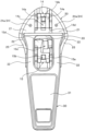
- FIG. 1 is a perspective view schematically showing a slider body and a handle of a slider according to an embodiment of the present invention.
- FIG. 2 is a plan view of the slider body and the handle shown in FIG. 1;
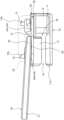
- FIG. 2 is a side view of the slider body and handle shown in FIG. 1;
- FIG. 2 is a schematic diagram showing an enlarged view of the main parts of the slider body and the handle.
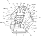
- FIG. 3 is a perspective view of the slider body.
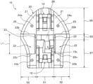
- FIG. 3 is a plan view of the slider body.
- FIG. 3 is a side view of the slider body.
- FIG. 2 is an exploded perspective view showing a conventional slider in an exploded state.
- FIG. 1 is a perspective view schematically showing a slider body and a handle in the slider of this embodiment.
- 2 and 3 are a plan view and a side view of the slider body and the handle, respectively.
- the cover body is shown by a broken line.
- FIG. 4 is a schematic diagram showing the relationship between the upper wing plate of the slider body and the handle.
- the front-rear direction refers to the length direction or sliding direction of the slider.
- the direction in which the slider moves so as to engage the left and right element rows is defined as the front (shoulder side direction), and the direction in which the slider moves so as to separate the element rows (posterior side direction). is the rear.
- the vertical direction refers to the height direction of the slider, and is, for example, a direction perpendicular to the later-described reference plane of the upper wing plate in the slider fuselage.
- the side where the handle is attached to the slider body of the slider is defined as the upper side, and the direction opposite to that side is defined as the lower side.
- the left-right direction refers to the width direction of the slider, and is a direction perpendicular to the length direction and height direction of the slider.
- the slider of this embodiment is used by being slidably attached to the left and right element rows of the slide fastener.
- the left and right element rows provided on the slide fastener are formed by a plurality of continuous coiled fastener elements.
- the slider is attached to the element row by inserting the coiled element row into an element guide path 18 (described later) of the slider. Furthermore, by sliding the slider along the element rows, the left and right element rows can be engaged and separated.
- the slider of this embodiment is provided with an automatic stop mechanism using a stop claw body (not shown) that can automatically maintain the stopped state of the slider when the slider is stopped with respect to the element row.
- the slider of the present invention may be formed without providing an automatic stop mechanism.
- the slider of this embodiment is formed of five parts: a slider body 10, a puller 30, a stop claw body (not shown), an elastic member (not shown), and a cover body 40.
- the elastic member is formed of a leaf spring member.
- the slider of this embodiment has main features in the slider body 10 (in particular, the upper wing plate 20 of the slider body 10), and in the present invention, a stop claw body, an elastic member (plate spring member), and a cover
- a stop claw body for example, the slider body 10 and the handle 30
- an elastic member plate spring member
- a cover body 40 is formed substantially in the same manner as those commonly used in the past.
- the pull handle 30 connects a pull body part 31 that is pinched with fingers or the like, left and right arm parts 32 extending from one end of the pull body part 31, and the tips of the left and right arm parts 32. It has a mounting shaft portion 33. A cross section of the mounting shaft portion 33 perpendicular to the axial direction (slider width direction) is circular.
- the handle 30 has a rectangular opening window surrounded by a handle main body 31, left and right arm parts 32, and a mounting shaft part 33.
- the shape, size, material, etc. of the handle are not particularly limited.
- the slider fuselage 10 of the present embodiment includes an upper wing plate 20, a lower wing plate 11 arranged apart from the upper wing plate 20, a front end portion (shoulder side end portion) of the upper wing plate 20, and a lower wing plate 11.
- a connecting column 12 that connects the front ends (ends on the shoulder side) of the upper wing plate 20, left and right upper flanges 13 provided on the left and right sides of the upper wing plate 20, and a front first It has a mounting post (front mounting post) 14 and a second rear mounting post (rear mounting post) 15 provided at the rear end of the upper wing plate 20 .
- Left and right protrusions that bulge toward the upper wing plate 20 are provided on the left and right side edges of the rear half of the lower wing plate 11 .
- left and right shoulders 16 are formed with a connecting column 12 in between.
- a rear opening 17 is formed at the rear end of the slider body 10.
- a substantially Y-shaped element guide path 18 is formed between the upper wing plate 20 and the lower wing plate 11 of the slider body 10 and communicates between the left and right shoulder openings 16 and the rear opening 17.
- Tape insertion gaps 19 are provided at the left and right edges of the slider body 10, respectively, through which left and right fastener tapes (not shown) of the slide fastener are inserted.
- the left and right tape insertion gaps 19 in the slider body 10 are formed between the left and right upper flange portions 13 and the raised portions 11a of the lower wing plate 11.
- the upper wing plate 20 of this embodiment includes a reference surface 21 exposed upward, left and right relief recesses 22 having a recessed shape with respect to the reference surface 21, and a handle 30. It has left and right shaft support parts 23 that support the mounting shaft part 33, four protrusions 24 protruding from the reference surface 21, and left and right side edges 25 having smooth curved outer surfaces.
- the portions disposed on both left and right sides of the central region 51 are defined as side regions 52.
- a portion between the first mounting post 14 and the second mounting post 15 is defined as an intermediate region 55, and The portions formed at the rear are defined as a front region 56 and a rear region 57, respectively.
- the intermediate region 55 of the upper wing plate 20 extends from the rear end edge of the first mounting post 14 (specifically, from the rear end edge of the first inclined surface 14d of the first mounting post 14 described later) to the second This is an area in the front-rear direction up to the front edge of the mounting post 15 (specifically, the front edge of a second inclined surface 15d of the second mounting post 15, which will be described later).
- the reference surface 21 of the upper wing plate 20 is an upper surface of the upper wing plate 20 that is perpendicular to the vertical direction, and is formed of a flat surface.
- This reference plane 21 is arranged in each of the left and right side regions 52 of the upper wing plate 20 in the left-right direction. Further, this reference plane 21 is provided in at least a portion of the front region 56 and at least a portion of the rear region 57 of the upper wing plate 20 in the front-rear direction.
- the flat reference surface (upper surface) 21 is connected to the left and right side regions 52 at the front end where the width dimension (horizontal dimension) of the upper wing plate 20 gradually decreases forward, and the left and right side regions 52 of the upper wing plate 20.
- the insertion process of inserting the left and right element rows into the slider can be smoothly performed. It can be carried out.
- an insertion step is performed in which the left and right element rows of the fastener chain are mechanically inserted into the element guide path 18 of the slider.
- this insertion step in order to insert the element row into the slider, first, using a slider holder, the front and rear ends of the upper wing plate 20 and the front and rear ends of the lower wing plate 11 in the slider body 10 are inserted. The slider is held in the slider holder by pinching and pressing the end portions from above and below.
- the slider holder Since the slider can be stably held in a constant posture, the machine can smoothly and stably insert the left and right element rows into the element guide path 18 of the slider.
- the four protrusions 24 provided on the upper wing plate 20 are formed to have the same shape and size.
- Each protrusion 24 has a circular tip surface (upper end surface) parallel to the reference surface 21 of the upper wing plate 20 and an outer circumferential surface extending from the outer peripheral edge of the tip surface to the reference surface 21. Further, the outer circumferential surface of the protrusion 24 is formed into a substantially spherical shape. Note that in the present invention, the shape of the protrusion 24 is not particularly limited.
- the protrusions 24 of this embodiment include a pair of left and right first protrusions 24a disposed forward of the intermediate region 55 of the upper wing plate 20 and on both left and right sides of the first mounting post 14; 20 and a pair of left and right second protrusions 24b arranged on both left and right sides of the second mounting post 15.
- the first protrusions 24a on the front side are arranged in the left and right side regions 52 of the front region 56 of the upper wing plate 20, respectively.
- the second protrusions 24b on the rear side are arranged in the left and right side regions 52 of the rear region 57 of the upper wing plate 20, respectively.
- the height dimension of the protrusion 24 from the reference plane 21 is the thickness dimension of the upper wing plate 20 ( That is, it is 3% or more and 20% or less, preferably 5% or more and 15% or less of the dimension in the vertical direction from the element guide surface facing the element guide path 18 of the upper wing plate 20 to the reference surface 21.
- the handle 30 By setting the height of the projection 24 to 3% or more of the thickness of the upper wing plate 20, when the handle 30 is tilted toward the shoulder 16 side or the rear opening 17 side with respect to the slider body 10, The handle 30 can be brought into contact with the left and right protrusions 24 and supported by the protrusions 24, thereby making it possible to separate the handle 30 from the reference plane 21 of the upper wing plate 20 at least in the vicinity of the protrusions 24 in the front-rear direction. can.
- the protrusion 24 By setting the height of the protrusion 24 to 20% or less of the thickness of the upper wing plate 20, the protrusion 24 can be made less noticeable in the slider's appearance. Further, for example, when the slider body 10 is touched with a finger, it is possible to make it difficult for the finger to get caught on the protrusion 24. Specifically, for example, in the case of this embodiment, the height of the protrusion 24 from the reference surface 21 is set to 0.05 mm or more and 0.30 mm or less.
- the first protrusion 24a on the front side is arranged closer to the intermediate region 55 than the second protrusion 24b on the rear side in the front-rear direction.
- the relief recesses 22 are provided in the left and right side regions 52 of the upper wing plate 20, respectively, in order to reduce the area in which the pull handle 30 contacts the upper wing plate 20 when the pull handle 30 is tilted toward the rear port 17 side. , and is formed to be recessed downward with respect to the reference plane 21 of the upper wing plate 20.
- the left and right relief recesses 22 are formed symmetrically with respect to the center line of the upper wing plate 20 in the left and right direction.
- Each of the left and right relief recesses 22 has a bottom surface 22a that curves concavely downward in the front-rear direction, and this bottom surface 22a is formed into a smooth concave curved surface. That is, the depth of the relief recess 22 is the deepest at the center portion in the length direction of the relief recess 22, and the depth of the relief recess 22 becomes deeper as it moves away from the center portion of the relief recess 22 toward the front and rear. It is formed so that the depth gradually becomes shallower.
- the depth of the relief recess 22 refers to the dimension from the bottom surface 22a of the relief recess 22 to the reference surface 21 in the vertical direction.
- the maximum depth D of the relief recess 22 (that is, the depth at the central portion of the relief recess 22) is 2% or more and 10% or less, preferably 3% or more and 8% or less of the thickness dimension of the upper wing plate 20. % or less (see Figure 4). Further, the maximum depth D of the escape recess 22 is set to 25% or more and 50% or less of the height of the protrusion 24 from the reference surface 21.
- the maximum depth D of the relief recess 22 is 2% or more of the thickness dimension of the upper wing plate 20, as shown in FIG. , it is possible to easily provide a gap (for example, a gap of 0.03 mm or more) between the handle 30 and the bottom surface 22a of the relief recess 22. Further, since the maximum depth D of the relief recess 22 is 10% or less of the thickness dimension of the upper wing plate 20, it is possible to suppress the strength of the upper blade 20 from decreasing due to the installation of the relief recess 22. For example, in the case of this embodiment, the maximum depth D of the relief recess 22 is set to 0.02 mm or more and 0.5 mm or less.
- the relief recess 22 is configured such that the bottom surface 22a of the relief recess 22 includes a plane parallel to the front-rear direction or a plane inclined with respect to the front-rear direction, instead of a curved surface as in the present embodiment. may be formed.
- the bottom surface 22a of the relief recess 22 and the reference surfaces provided before and after the relief recess 22 are shown. 21, but in the actual slider body 10, as shown in FIG. It is formed smoothly and continuously from the front and rear reference planes 21 so that it cannot be clearly seen.
- the area (contact area) where the pull tab 30 directly contacts the upper wing plate 20 can be made smaller than, for example, when the relief recess 22 is not provided in the upper wing plate 20.
- each of the left and right relief recesses 22 may be formed to extend inward in the left-right direction to the boundary position between the central region 51 and the side regions 52.
- the bottom surface 22a of the relief recess 22 extends parallel to the left-right direction, and thus has a constant surface shape along the left-right direction.
- the bottom surfaces 22a of the left and right relief recesses 22 are formed smoothly so as to be continuous with the front and rear reference surfaces 21, and are also formed parallel to the left and right direction, thereby creating a concave shape relief. Even if the recess 22 is provided on the upper surface of the upper wing plate 20, the relief recess 22 can be made less noticeable in the appearance of the slider. Therefore, the influence of the escape recess 22 on the appearance quality of the slider can be reduced or eliminated.
- each of the left and right relief recesses 22 is formed to include at least a portion of the intermediate region 55, preferably the entire intermediate region 55, in the front-rear direction (see FIG. 6).
- the front end (front end edge) 22b of the relief recess 22 is arranged forward of the intermediate region 55 in the front-rear direction, and specifically, 24a.
- the rear end (rear end edge) 22c of the escape recess 22 is arranged rearward of the intermediate region 55 in the front-rear direction, and specifically, between the intermediate region 55 and the second protrusion 24b on the rear side. It is arranged in Thereby, when the handle 30 falls toward the rear port 17 side, the area in which the handle 30 contacts the upper wing plate 20 can be stably reduced.
- the relief recess 22 has a dimension in the front-rear direction from the intermediate region 55 to the rear end 22c of the relief recess 22 that is larger than a dimension in the front-rear direction from the intermediate region 55 to the front end 22b of the relief recess 22. It is provided.
- the upper wing plate The relief recess 22 can be made smaller in the front-rear direction while ensuring the effect of reducing the contact area of the pull handle 30 with respect to the handle 20.
- the length L1 of the relief recess 22 is equal to the length L1 of the relief recess 22. It is set larger than the dimension in the front-rear direction at , and smaller than the dimension in the front-rear direction from the first protrusion 24a on the front side to the second protrusion 24b on the rear side.
- the tip of the protrusion 24 on the rear side of the upper wing plate 20 is defined as the standard dimension L2
- the length dimension L1 of the relief recess 22 is 50% of the standard dimension L2. % or more (see Figure 4).
- the length L1 of the relief recess 22 is set to 100% or less of the reference dimension L2. Therefore, it is possible to suppress a decrease in the strength of the upper wing plate 20 due to the installation of the relief recess 22, and it is also possible to provide the relief recess 22 in the upper wing plate 20 so that it is not easily noticeable in the appearance of the slider.
- the left and right relief recesses 22 may be provided with a size that includes at least a portion of the intermediate region 55 in the front-rear direction.
- the relief recess 22 may be formed such that the front end 22b of the relief recess 22 is disposed within the intermediate region 55, or the second projection 22 may be formed from a position in front of the first projection 24a. It may be formed continuously in the front-rear direction up to a position on the rear side of 24b.
- the left and right shaft support parts 23 provided on the upper wing plate 20 are provided in an intermediate region 55 between the first mounting post 14 and the second mounting post 15 so as to support the mounting shaft part 33 of the handle 30.
- the support surfaces (upper surfaces) of the left and right shaft support portions 23 are arranged at the same height position as the reference surface 21 of the upper wing plate 20 in the vertical direction. That is, the reference surface 21 of the upper wing plate 20 and the support surface of the shaft support portion 23 are provided so as to form one flat same plane (single flat surface). Therefore, the support surfaces of the left and right shaft support parts 23 are arranged above the bottom surface 22a of the escape recess 22 in the vertical direction. Thereby, when the handle 30 falls toward the rear opening 17, a gap can be easily formed between the handle 30 and the bottom surface 22a of the escape recess 22.
- the left and right shaft support parts 23 are each formed to be elongated in the front-rear direction over the entire intermediate region 55, for example, in a plan view of the slider body 10 (see FIG. 6). Furthermore, the left and right shaft support parts 23 are disposed so as to be sandwiched between the left and right relief recesses 22 in the left and right direction (that is, in the range inside the left and right relief recesses 22), and are also disposed between the central region 51 and the left and right relief recesses 22. It is provided so as to include the boundary of the side region 52.
- a central recess 26 is provided between the left and right shaft support parts 23 so that the central part in the width direction is the lowest, so the left and right shaft support parts 23 are spaced apart from each other. has been done.
- the present embodiment can be used for, for example, a rotating type handle in which the left and right arm portions and the mounting shaft portion of the pull are formed in an arc shape.
- the shaft support portion 23 of the upper wing plate 20 is provided such that at least a portion of the shaft support portion 23 is disposed within the vertical intermediate region 55 when the slider body 10 is viewed from above.
- one shaft support part may be provided in the center region in the left and right direction, or, for example, a pair of left and right shaft support parts may be provided closer to the outside in the width direction in the left and right side regions. may be provided in each part.
- the shaft support portion may be provided not in the entire intermediate region but only in a part of the intermediate region in the front-rear direction.
- the support surface of the shaft support part 23 is disposed at the same height position in the vertical direction as the reference surface 21 of the upper wing plate 20, as described above. may be formed by changing the height position of the support surface within the range from the reference surface of the upper wing plate to the tip surface of the protrusion in the vertical direction.
- the first mounting post 14 and the second mounting post 15 are formed to extend upward from the upper wing plate 20. Further, the first mounting post 14 and the second mounting post 15 are spaced apart from each other in the front-rear direction. Therefore, a space is provided between the first mounting post 14 and the second mounting post 15 in which the mounting shaft portion 33 of the handle 30 can be accommodated.
- the cover body 40 is attached to the slider body 10 by covering and fixing the cover body 40 over the first attachment column 14 and the second attachment column 15 of the slider body 10 (see FIG. 3).
- the cover body 40 is placed on the first mounting column 14 and the second mounting column 15, and then partially pressed and plastically deformed to form the first mounting column. 14 and the second mounting column 15.
- the method and means for fixing the cover body 40 to the first mounting post 14 and the second mounting post 15 of the slider body 10 are not particularly limited.
- first mounting post 14 In order to attach a plate spring member (elastic member) (not shown) to the front first mounting column 14, left and right first spring support parts 14a that support the plate spring member, and a first protrusion that engages with the plate spring member are provided. A portion 14b is provided. Further, the first mounting post 14 is provided with a pawl accommodating recess 14c that accommodates a portion of a stop pawl (not shown), and a first inclined surface 14d that slopes downward toward the rear. The first inclined surface 14d of the first mounting post 14 is provided at the rear end of the first mounting post 14 facing the second mounting post 15.
- a second spring support part 15a that supports the plate spring member, and a plate that protrudes above the second spring support part 15a are provided.
- a second protrusion 15b that engages with the spring member is provided.
- the second mounting post 15 is provided with a claw hole 15c that communicates with the element guide path 18, and a second inclined surface 15d that slopes downwardly toward the front.
- first mounting post 14 and the second mounting post 15 of the slider body 10 are formed so that at least the cover body 40 can be attached, the first mounting post 14 and the second mounting post 15 are The shape, structure, size, etc. are not particularly limited.
- the upper wing of the slider body 10 is assembled.
- the handle 30 is placed on the plate 20.
- the mounting shaft 33 of the handle 30 is inserted between the first mounting post 14 and the second mounting post 15 of the slider body 10, and the inside of the opening window of the handle 30 is inserted. Insert the first mounting post 14 or the second mounting post 15 into.
- the attachment shaft portion 33 of the handle 30 is placed on the left and right shaft support portions 23 of the upper wing plate 20, the attachment shaft portion 33 is supported by the shaft support portion 23.
- the stop claw body and the elastic member are placed in order on the slider body 10 on which the handle 30 is placed.
- a part of the stop pawl body is inserted into the pawl accommodating recess 14c provided in the first mounting post 14 of the slider body 10, and the pawl part of the stop pawl is mounted on the second mounting column 14. It is inserted into the claw hole 15c provided in the pillar 15.
- the cover body 40 is attached to the slider body 10 on which the handle 30, the stop claw body, and the elastic member are mounted. At this time, the cover body 40 is placed over the first attachment column 14 and the second attachment column 15 of the slider body 10 so that the first attachment column 14 and the second attachment column 15 are accommodated in the cover body 40 . Furthermore, the cover body 40 is fixed to the first mounting post 14 and the second mounting post 15 by pressing a part of the cover body 40 to plastically deform it. As a result, the attachment shaft portion 33 of the handle 30 is arranged between the first attachment column 14 and the second attachment column 15 of the slider body 10, and the attachment shaft portion 33 is located between the upper wing plate 20 and the cover body 40.
- the slider of this embodiment held in is manufactured.
- the mounting shaft portion 33 of the handle 30 is attached to the left and right sides of the slider body 10. It is supported by the shaft support part 23, and the left and right arm parts 32 of the handle 30 are supported by the left and right second protrusions 24b of the slider body 10 (see FIG. 4).
- the pull handle 30 is supported by the slider body 10 by contacting only the left and right shaft support portions 23 and the left and right second protrusions 24b as a portion of the slider body 10 that supports the pull handle 30.
- left and right relief recesses 22 are provided in left and right side regions 52 of the upper wing plate 20. Thereby, a gap can be provided between the bottom surface 22a of the escape recess 22 and the pull tab 30.
- the handle 30 is located between the upper wing plate 20 and the puller 30 that has fallen backward.
- a non-contact area 59 is provided that does not contact the plate 20.
- the non-contact area 59 is provided at least in the range from the front edge of the second mounting post 15 to the rear end 22c of the relief recess 22 in the front-rear direction. Note that the range from the position of the front edge of the second mounting post 15 to the position of the rear end 22c of the relief recess 22 can also be referred to as the range within the rear region 57 where the relief recess 22 is provided.
- the non-contact area 59 extends from the center position of the attachment shaft 33 of the handle 30 to the contact position between the handle 30 and the second protrusion 24b in the front-rear direction (i.e., the range of the reference dimension L2). range).
- the pull handle 30 may be moved between the left and right shaft supports 23 and the left and right shaft supports. may be in contact with the slider body 10 at a portion other than the second protrusion 24b.
- the mounting shaft portion 33 of the handle 30 is supported by the left and right shaft support portions 23 of the slider body 10, and the left and right of the handle 30 is The arm portions 32 are supported by the left and right first projections 24a of the slider body 10.
- the first protrusion 24a on the front side is located closer to the attachment shaft 33 of the handle 30 than the second protrusion 24b on the rear side in a side view of the slider (for example, see FIG. 3). .
- the handle 30 when the handle 30 is tilted forward, the handle 30 can be held at a larger inclination angle relative to the reference plane 21 of the upper wing plate 20 than when the handle 30 is tilted backward, for example. , the area in which the handle 30 contacts the upper wing plate 20 can be kept small.
- the handle 30 and the upper wing plate 20 of the slider body 10 can The contact area of the slider can be made much smaller than, for example, a conventional general slider. Therefore, when the slider of this embodiment is subjected to a painting process such as spray painting, and then the painted slider is dried, there is a problem that the pull tab 30 becomes stuck to the upper wing plate 20 due to drying of the paint. Also, it is possible to prevent the problem of the handle 30 remaining on the slider body 10 due to the pull handle 30 being stuck. This makes it possible to reduce coating defects on the slider, thereby increasing the productivity of the slider and the yield of the slider.
- the left and right relief recesses 22 in the upper wing plate 20 are formed parallel to the left and right direction, and are formed continuously up to the left and right side edges 25 of the upper wing plate 20. . Therefore, when painting the slider by spraying, the paint flowing into the relief recess 22 of the upper wing plate 20 can be easily discharged outward in the left and right direction, making it difficult for paint to accumulate in the relief recess 22 and removing the slider. Can be painted beautifully.
- left and right relief recesses 22 are continuously formed up to the left and right side edges 25 of the upper wing plate 20, for example, a puller on the slider body 10 whose mounting shaft portion has a different horizontal dimension from this embodiment. Even if a handle (for example, a handle whose attachment shaft portion is long in the left-right direction) is attached, it is possible to prevent or suppress the handle from sticking to the upper wing plate 20 after painting, as in the case of this embodiment.
- the bottom surface 22a of the relief recess 22 is formed into a smooth concave shape, and is smoothly continuous with the front and rear reference surfaces 21. Furthermore, the relief recess 22 is formed to have a shallow depth relative to the reference surface 21, and its dimension in the front and back direction is reduced to the extent that the contact area between the pull tab 30 and the upper wing plate 20 can be reduced. It is formed as follows. Furthermore, in the slider of this embodiment, when the pull tab 30 is tilted toward the rear opening 17, as shown in FIGS. It can be covered to make it less visible.
- the slider of this embodiment can provide the same texture as a conventional slider.
- the slider of this embodiment is attached to the element row of a fastener chain, for example, instead of a conventional slider, it is possible to prevent the user from feeling uncomfortable. Further, it is possible to suppress changes in the influence of slide fasteners on the appearance, design, etc. of zippered products such as clothes and bags.
- the slider of the embodiment described above is mainly used for a slide fastener in which the element row is formed by a plurality of continuous fastener elements in a coil shape, as described above.
- the slider of the present invention can be applied to, for example, a slide fastener in which an element row is formed by a plurality of metal fastener elements, or a slide fastener in which a plurality of independent fastener elements are formed on a fastener tape by injection molding of synthetic resin. It may be formed to be used.
- the upper wing plate 20 is provided with four protrusions 24, including two first protrusions 24a on the front side and two second protrusions 24b on the rear side.
- the slider body may be formed without providing a protrusion on the front side of the intermediate region, for example.
Landscapes
- Slide Fasteners (AREA)
- Knives (AREA)
Priority Applications (5)
| Application Number | Priority Date | Filing Date | Title |
|---|---|---|---|
| CN202280092339.1A CN118785830A (zh) | 2022-05-16 | 2022-05-16 | 拉头 |
| JP2024521405A JP7710103B2 (ja) | 2022-05-16 | 2022-05-16 | スライダー |
| PCT/JP2022/020431 WO2023223397A1 (ja) | 2022-05-16 | 2022-05-16 | スライダー |
| US18/837,368 US20250169579A1 (en) | 2022-05-16 | 2022-05-16 | Slider |
| DE112022007225.3T DE112022007225T5 (de) | 2022-05-16 | 2022-05-16 | Schieber |
Applications Claiming Priority (1)
| Application Number | Priority Date | Filing Date | Title |
|---|---|---|---|
| PCT/JP2022/020431 WO2023223397A1 (ja) | 2022-05-16 | 2022-05-16 | スライダー |
Publications (1)
| Publication Number | Publication Date |
|---|---|
| WO2023223397A1 true WO2023223397A1 (ja) | 2023-11-23 |
Family
ID=88834825
Family Applications (1)
| Application Number | Title | Priority Date | Filing Date |
|---|---|---|---|
| PCT/JP2022/020431 Ceased WO2023223397A1 (ja) | 2022-05-16 | 2022-05-16 | スライダー |
Country Status (5)
| Country | Link |
|---|---|
| US (1) | US20250169579A1 (https=) |
| JP (1) | JP7710103B2 (https=) |
| CN (1) | CN118785830A (https=) |
| DE (1) | DE112022007225T5 (https=) |
| WO (1) | WO2023223397A1 (https=) |
Citations (4)
| Publication number | Priority date | Publication date | Assignee | Title |
|---|---|---|---|---|
| JPH07213311A (ja) * | 1994-01-19 | 1995-08-15 | Friedrich Mayerhofer | ジッパーファスナーすべり具の製造方法および機械とジッパーファスナーすべり具 |
| JPH09168412A (ja) * | 1995-12-21 | 1997-06-30 | Ykk Corp | スライドファスナー用スライダー |
| WO2016189616A1 (ja) * | 2015-05-25 | 2016-12-01 | Ykk株式会社 | スライドファスナーのスライダー |
| WO2021250748A1 (ja) * | 2020-06-08 | 2021-12-16 | Ykk株式会社 | スライダー |
Family Cites Families (4)
| Publication number | Priority date | Publication date | Assignee | Title |
|---|---|---|---|---|
| EP2517594B1 (en) * | 2009-12-25 | 2016-07-20 | YKK Corporation | Slider for slide fastener |
| WO2012042657A1 (ja) * | 2010-09-30 | 2012-04-05 | Ykk株式会社 | スライドファスナー用スライダー |
| TWI480008B (zh) * | 2013-05-20 | 2015-04-11 | Chung Chwan Entpr Co Ltd | 具有內表面凹陷特徵的帽蓋結構及拉鍊頭組合結構 |
| TWI592106B (zh) * | 2015-03-13 | 2017-07-21 | 中傳企業股份有限公司 | 用於提升抗扭強度的拉鍊頭組合結構及其滑動件 |
-
2022
- 2022-05-16 JP JP2024521405A patent/JP7710103B2/ja active Active
- 2022-05-16 US US18/837,368 patent/US20250169579A1/en active Pending
- 2022-05-16 DE DE112022007225.3T patent/DE112022007225T5/de active Pending
- 2022-05-16 CN CN202280092339.1A patent/CN118785830A/zh active Pending
- 2022-05-16 WO PCT/JP2022/020431 patent/WO2023223397A1/ja not_active Ceased
Patent Citations (4)
| Publication number | Priority date | Publication date | Assignee | Title |
|---|---|---|---|---|
| JPH07213311A (ja) * | 1994-01-19 | 1995-08-15 | Friedrich Mayerhofer | ジッパーファスナーすべり具の製造方法および機械とジッパーファスナーすべり具 |
| JPH09168412A (ja) * | 1995-12-21 | 1997-06-30 | Ykk Corp | スライドファスナー用スライダー |
| WO2016189616A1 (ja) * | 2015-05-25 | 2016-12-01 | Ykk株式会社 | スライドファスナーのスライダー |
| WO2021250748A1 (ja) * | 2020-06-08 | 2021-12-16 | Ykk株式会社 | スライダー |
Also Published As
| Publication number | Publication date |
|---|---|
| US20250169579A1 (en) | 2025-05-29 |
| JPWO2023223397A1 (https=) | 2023-11-23 |
| DE112022007225T5 (de) | 2025-03-13 |
| CN118785830A (zh) | 2024-10-15 |
| JP7710103B2 (ja) | 2025-07-17 |
Similar Documents
| Publication | Publication Date | Title |
|---|---|---|
| JPH0727849Y2 (ja) | スライドファスナー用スライダーの引手 | |
| CN100592880C (zh) | 拉链 | |
| JP6220080B2 (ja) | ファスナーエレメント、ファスナーストリンガー及びスライドファスナー | |
| US9788615B2 (en) | Fastener stringer | |
| US8806725B2 (en) | Slide fastener | |
| JP3379005B2 (ja) | 停止装置付スライドファスナー用スライダー | |
| JP7023242B2 (ja) | スライドファスナー用スライダー | |
| EP3900570A1 (en) | Slider for slide fastener | |
| JP5989103B2 (ja) | スライドファスナー用スライダー | |
| WO2023223397A1 (ja) | スライダー | |
| TWI620522B (zh) | Zipper chain and zipper chain | |
| CN113795173B (zh) | 拉链 | |
| JPH0628602B2 (ja) | スライドフアスナ用スライダ | |
| JPS5925219Y2 (ja) | スライドフアスナ_の下止 | |
| US20240115014A1 (en) | Decoration Receiving Element, Slider and Decoration Receiving Element, and Hidden Slide Fastener | |
| US10869525B2 (en) | Slider for slide fastener | |
| CN209965409U (zh) | 拉链用拉头 | |
| WO2013091712A1 (en) | Fastener element for a slide fastener, and methods for the manufacture thereof | |
| JP3247906U (ja) | スライダー及びスライドファスナー | |
| JP5844386B2 (ja) | 停止機構付きスライダー | |
| US3153831A (en) | Lock slider | |
| CN223667402U (zh) | 拉链用的拉头 | |
| WO2025191802A1 (ja) | スライドファスナー用スライダー | |
| CN109770484B (zh) | 用于拉链的止挡件以及拉链的制造方法 | |
| CN2312605Y (zh) | 一种供拉动件钩扣的拉链头 |
Legal Events
| Date | Code | Title | Description |
|---|---|---|---|
| 121 | Ep: the epo has been informed by wipo that ep was designated in this application |
Ref document number: 22942602 Country of ref document: EP Kind code of ref document: A1 |
|
| ENP | Entry into the national phase |
Ref document number: 2024521405 Country of ref document: JP Kind code of ref document: A |
|
| WWE | Wipo information: entry into national phase |
Ref document number: 18837368 Country of ref document: US |
|
| WWE | Wipo information: entry into national phase |
Ref document number: 202280092339.1 Country of ref document: CN |
|
| WWE | Wipo information: entry into national phase |
Ref document number: 112022007225 Country of ref document: DE |
|
| WWP | Wipo information: published in national office |
Ref document number: 112022007225 Country of ref document: DE |
|
| 122 | Ep: pct application non-entry in european phase |
Ref document number: 22942602 Country of ref document: EP Kind code of ref document: A1 |
|
| WWP | Wipo information: published in national office |
Ref document number: 18837368 Country of ref document: US |