WO2023223370A1 - 冠動脈運動シミュレータ及び血管モデル - Google Patents
冠動脈運動シミュレータ及び血管モデル Download PDFInfo
- Publication number
- WO2023223370A1 WO2023223370A1 PCT/JP2022/020300 JP2022020300W WO2023223370A1 WO 2023223370 A1 WO2023223370 A1 WO 2023223370A1 JP 2022020300 W JP2022020300 W JP 2022020300W WO 2023223370 A1 WO2023223370 A1 WO 2023223370A1
- Authority
- WO
- WIPO (PCT)
- Prior art keywords
- coronary artery
- blood vessel
- model
- motion simulator
- vessel model
- Prior art date
- Legal status (The legal status is an assumption and is not a legal conclusion. Google has not performed a legal analysis and makes no representation as to the accuracy of the status listed.)
- Ceased
Links
Images




Classifications
-
- G—PHYSICS
- G09—EDUCATION; CRYPTOGRAPHY; DISPLAY; ADVERTISING; SEALS
- G09B—EDUCATIONAL OR DEMONSTRATION APPLIANCES; APPLIANCES FOR TEACHING, OR COMMUNICATING WITH, THE BLIND, DEAF OR MUTE; MODELS; PLANETARIA; GLOBES; MAPS; DIAGRAMS
- G09B23/00—Models for scientific, medical, or mathematical purposes, e.g. full-sized devices for demonstration purposes
- G09B23/28—Models for scientific, medical, or mathematical purposes, e.g. full-sized devices for demonstration purposes for medicine
-
- G—PHYSICS
- G09—EDUCATION; CRYPTOGRAPHY; DISPLAY; ADVERTISING; SEALS
- G09B—EDUCATIONAL OR DEMONSTRATION APPLIANCES; APPLIANCES FOR TEACHING, OR COMMUNICATING WITH, THE BLIND, DEAF OR MUTE; MODELS; PLANETARIA; GLOBES; MAPS; DIAGRAMS
- G09B9/00—Simulators for teaching or training purposes
Definitions
- the present invention relates to a coronary artery motion simulator that simulates the movement of coronary arteries associated with heart beats, and a blood vessel model used therein.
- Coronary arteries are blood vessels that send blood to the surface of the heart in order to move the myocardium, and are made up of two branches, the left and right coronary arteries, which branch from the root of the aorta to the left and right.
- the left coronary artery is a very important blood vessel that supplies blood containing oxygen and nutrients to move the left ventricular myocardium, which plays a role in pumping blood throughout the body.
- This left coronary artery along the way from the main trunk (LMT: Left main truck) that connects to the aorta, has an anterior descending artery (LAD: Left anterior descending coronary artery) and a circumflex artery (LCx: Left circumflex artery). flex coronary artery).
- the anterior descending artery is primarily responsible for supplying blood to the anterior wall of the left ventricle and the myocardial septum, and the circumflex artery (LCx) is responsible for supplying blood from the lateral wall to the posterior wall of the left ventricle.
- LAD anterior descending artery
- LCx circumflex artery
- the main treatments for ischemic heart disease include drug therapy, coronary artery bypass surgery, which involves creating a detour blood vessel before and after the narrowing, and percutaneous coronary angioplasty using a catheter.
- coronary artery bypass surgery which involves creating a detour blood vessel before and after the narrowing
- percutaneous coronary angioplasty using a catheter are known.
- Coronary artery intervention using a stent is one type of percutaneous coronary angioplasty.
- a metal mesh stent crimped onto a thin polymer film balloon is inserted through a blood vessel at the base of the thigh or wrist using a catheter.
- the stenotic lesion is expanded by the stent and compressed into the blood vessel, ensuring blood flow.
- left main branch branch lesion is a condition in which stenosis or occlusion occurs in the blood vessels at the base of the anterior descending artery (LAD) and circumflex artery (LCx), which branch from the main trunk (LMT).
- LAD anterior descending artery
- LCx circumflex artery
- LMT main trunk
- stent treatment for lesions at the main bifurcation of the left coronary artery has poor long-term results, and many clinical techniques are being considered to improve treatment results.
- advances in drug-eluting stents have improved treatment outcomes, and coronary artery intervention has become acceptable for the treatment of relatively simple left main coronary artery bifurcation lesions that can be treated with a single stent. became.
- Clinical treatment of the main branch of the left coronary artery is performed while the heart is beating, so it is difficult to identify the structure of the stent within the coronary artery on an X-ray fluoroscopic screen.
- the anterior descending artery (LAD) and circumflex artery (LCx) may appear to overlap due to the limited movement of the X-ray angiography equipment used in conjunction with the X-ray angiography system. Treatment is performed while observing from a substitute perspective that reduces the length of the .
- the present inventors have previously conducted research and development on stent treatment methods using an elastic blood vessel model that imitates the diameter and angle of the main branch branch vessel of the left coronary artery, and research on stent selection using the blood vessel model. (Refer to Non-Patent Document 1).
- the present invention was devised based on the above-mentioned problems and the knowledge of the inventor, and its purpose is to create a system with a relatively simple structure that simulates a coronary artery that moves with the heartbeat.
- the object of the present invention is to provide a coronary artery motion simulator and a blood vessel model that can test and evaluate medical devices such as stents and treatment methods.
- the present invention mainly provides a coronary artery movement simulator that simulates the movement of a coronary artery associated with heart beats, which includes a blood vessel model that simulates a predetermined portion of the coronary artery, and a blood vessel model that supports the blood vessel model.
- a model support unit holds the blood vessel model arranged at an angle with respect to its installation surface so as to be rotatable along a predetermined plane, and repeatedly performs the rotation motion in forward and reverse directions. Thereby, the displacement state of the blood vessel model accompanying the pulsation can be simulated.
- the present invention it is possible to simulate the movement of coronary arteries associated with contraction and expansion of a patient's heart using a simple mechanism and a simple drive system, and it is possible to more effectively treat coronary arteries in an environment that matches actual clinical conditions than before. This makes it possible to evaluate safety and safety.
- FIG. 2 is a conceptual diagram of the coronary artery motion simulator according to the present embodiment in a side view.
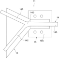
- FIG. 3 is a schematic front view of a simulated blood vessel unit.
- FIG. 2 is a schematic side view of a simulated blood vessel unit.
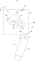
- FIG. 3 is a schematic plan view of the movable device. It is a schematic perspective view of a support body.
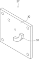
- FIG. 3 is a schematic perspective view of the fixing portion viewed from the top side.
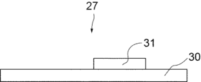
- FIG. 3 is a schematic front view of the fixing part.
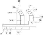
- FIG. 3 is a schematic perspective view of the operating section viewed from the back side.
- FIG. 3 is a schematic front view of the operating section.
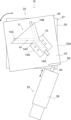
- FIG. 5 is a schematic plan view of the movable device for explaining a state in which the operating section rotates from the state shown in FIG. 4;
- FIG. 1 shows a conceptual diagram of the coronary artery motion simulator according to the present embodiment in a side view.
- the coronary artery motion simulator 10 supports a simulated blood vessel unit 11 including a part simulating the left main trunk branch of the coronary artery, which is a predetermined part of the coronary artery, and supports the simulated blood vessel unit 11.
- the model support unit 12 is configured to be able to simulate the operation of the left coronary artery main trunk branch.
- the simulated blood vessel unit 11 includes a Y-shaped blood vessel model 14 in a plan view that simulates a blood vessel near the main branch of the left coronary artery, and a blood vessel model 14 that is integrally fixed. It consists of a block-shaped base 15.
- the blood vessel model 14 is formed into an elastic tube shape from a material such as silicone, and has an elliptical cross section (lumen cross section) perpendicular to the direction in which the blood vessel extends in its inner lumen.
- This blood vessel model 14 has a main part 14A corresponding to the main trunk (LMT) of the left coronary artery, and branches from the main part 14A to correspond to the anterior descending artery (LAD) and circumflex artery (LCx) of the left coronary artery. It consists of branch parts 14B and 14C. Note that the intersection of the blood vessel axes of the main portion 14A and the branch portions 14B and 14C is referred to as a branch center 14D.
- the branch portions 14B and 14C branch into two branches from the main portion 14A in a plan view of FIG. 2, and are arranged so as to be bent from a branch center 14D with respect to the main portion 14A in a side view of FIG. Therefore, the blood vessel model 14 has a three-dimensional shape in which the blood vessel portion extends three-dimensionally.
- the ends of the main part 14A and the branch parts 14B and 14C are connected to another tube, and a part of the test circuit filled with liquid etc. will be placed in
- the base 15 has a bent shape corresponding to the bent state of the blood vessel model 14, and a part of the surface of the blood vessel model 14 is embedded therein.
- the part where the main part 14A is buried becomes a mounting part 15A that is attached to the model support unit 12.
- the model support unit 12 has a structure capable of simulating the displacement and rotational conditions of the coronary arteries associated with heart beats. As shown in FIG. 1, this model support unit 12 includes a tilting table 17 installed on a predetermined installation surface B, and a tilting arrangement placed on the top surface of the tilting table 17, and holding the simulated blood vessel unit 11.
- the movable device 18 has a mechanism for performing rotational operation in the state.
- the inclined table 17 is arranged at a predetermined inclination angle (for example, 35 degrees) from the distal end side of the installed part 20, which is the left side in FIG. It consists of a flat plate-shaped inclined surface part 21 that is arranged to be inclined upward in the figure toward the right side in the figure, and a side part 22 that stands up from the right end of the installation part 20 in the figure and supports the inclined surface part 21 from below. .
- a predetermined inclination angle for example, 35 degrees
- the movable device 18 has a structure capable of simulating the displacement of the blood vessel model 14 due to heart beats by rotating the simulated blood vessel unit 11 while being fixed to the inclined surface portion 21 of the inclined table 17. There is.
- this movable device 18 includes a support body 24 that is configured to be able to perform a predetermined rotational movement while supporting the simulated blood vessel unit 11, and a drive device 25 that operates the support body 24. It is equipped with
- the support body 24 includes a fixing portion 27 located at the lower side in the figure and fixed to the inclined table 17 (see FIG. 1), and a surface (predetermined surface) of the fixing portion 27.
- the operating part 28 is connected to the fixed part 27 so as to be relatively rotatable along the movement axis.
- the fixing section 27 includes a substantially rectangular plate-shaped main body 30 whose back surface is fixed to the inclined surface section 21 (see FIG. 1) with screws (not shown), and an inclined surface section.
- the rail 31 protrudes near the center of the upper surface of the main body 30 opposite to the rail 31 and extends in an arc shape.
- the operating section 28 includes a pedestal 33 having a substantially rectangular plate shape, and is arranged upright on the upper surface of the pedestal 33, and also includes a pedestal 33 having a substantially rectangular plate shape. ), a guide 35 protruding from the lower surface of the pedestal 33, and a drive device 25 (see FIG. 1, etc.) standing up from the outer edge of one corner on the upper surface of the pedestal 33. It is provided with a connecting part 36 to be connected.
- the model holding parts 34 have the same trapezoidal shape when viewed from the side and are arranged in parallel in the same direction.
- Each model holding section 34 is arranged such that the upper mounting surface 34A is inclined vertically at a predetermined inclination angle with respect to the upper surface of the pedestal 33.
- a base 15 (see FIG. 1, etc.) is detachably attached using screws (not shown) or the like.
- the blood vessel model 14 is arranged facing the pedestal 33, as shown in FIGS. 1 and 4.
- the model holding section 34 is fixed to the pedestal 33 in an oblique direction so that the back surface 34B, which is the short side thereof, faces the direction of the connecting section 36.
- the arrangement angle in plan view between the axis of the main part 14A of the attached blood vessel model 14 and the reference edge 33A (reference line) of the pedestal 33 is set at a predetermined angle. value (for example, 33 degrees).
- the pedestal 33 is arranged such that the reference edge 33A runs along the inclination direction of the inclined surface portion 21 (see FIG. 1).
- the guide 35 is made up of two large and small arc-shaped members arranged apart from each other with different diameters from the same center, and a fixed part is provided in the space S between these arc-shaped members. 27 rails 31 (see FIG. 6) are fitted together. Further, the guide 35 is capable of sliding along the rail 31, and due to the sliding, the surface of the main body 30 of the fixed part 27 is rotated about the center of the guide 35, as shown in FIG. The operating section 28 can be rotated along. As a result, the model holding section 34 and the simulated blood vessel unit 11 rotate with respect to the fixed section 27 together with the pedestal 33 .
- the shape and position of the rail 31 and the guide 35 are set to enable rotational oscillation that reciprocates the branch center 14D of the blood vessel model 14 attached to the model holder 34 within a predetermined angular range and movement amount range.
- Ru a range of a predetermined rotation angle (for example, 7.4 degrees) and a range of a predetermined movement amount (for example, 3.7 mm) from the initial position.
- the blood vessel model 14 is set to rotate and swing along the surface of the fixed part 27.
- the drive device 25 includes an actuator 38 that applies an external force to the support 24, and a control section 39 that includes a computer that controls the operation of the actuator 38.
- the actuator 38 is a linear actuator capable of linear reciprocating motion using a motor, and as shown in FIGS. It is connected to a connecting portion 36 near an end remote from the center of rotation of 28. Therefore, by driving the actuator 38, an external force is applied to the base 33 of the operating portion 28 while repeatedly pushing and pulling, thereby causing the operating portion 28 to move relative to the fixed portion 27 while the universal joint 40 is bent. That is, as shown in FIGS. 4 and 10, the actuator 38 reciprocates in one direction, and the operating section 28 rotates in forward and reverse directions along the surface of the main body 30 of the fixing section 27, and the simulated blood vessel unit 11 will swing within a predetermined range.
- the control unit 39 sets a drive time corresponding to the time from the diastole to the systole of the heart and a predetermined stop so that the blood vessel model 14 is displaced in accordance with the pulsation state of the heart, based on conditions specified by the user.
- the actuator 38 is driven in the forward direction at the same time, and the actuator 38 is repeatedly driven in a cycle that also includes driving in the opposite direction.
- the drive time is set in accordance with the assumed heart rate.
- the inclination angle of the tilting table 17, the inclination angle of the mounting surface 34A of the model holding part 34, and the arrangement angle of the model holding part 34 with respect to the reference edge 33A of the pedestal 33 are determined at the time of actual surgery.
- the angles are set to match the position and condition of the patient's left main trunk bifurcation.
- the displacement status of the left main trunk branch of the left coronary artery due to pulsation that is, the movement vector in the displacement direction in the predetermined reference coordinates, and the displacement amount.
- the rotation amount and the arrangement state at the initial position at the reference time are simulated.
- reciprocating motion in only one direction is performed without using a device such as a simulated heart that reproduces the motion of the heart in the six-axis directions, which requires a complicated mechanism or drive system.
- a device such as a simulated heart that reproduces the motion of the heart in the six-axis directions, which requires a complicated mechanism or drive system.
- the coronary artery motion simulator 10 of the present embodiment makes it possible to evaluate the effectiveness and safety of left coronary artery main branch bifurcation treatment in an environment that matches actual clinical practice.
- the displacement situation of the left coronary artery main branch is simulated, but the design values of each part of the model support unit 12 can be adjusted as appropriate by using a blood vessel model simulating other coronary artery parts. This allows evaluation at other sites as well.
- model support unit 12 in the present invention performs various movements of the coronary artery associated with heart beats, that is, displacement movements that imitate the movement vector and displacement amount of the coronary artery, and/or, depending on the region of the target coronary artery.
- Various structures can be adopted as long as they can simulate a rotational motion that mimics the amount and range of rotation of a coronary artery.
- each part of the device according to the present invention is not limited to the illustrated configuration example, and various changes can be made as long as substantially the same effect is achieved.
- Coronary artery motion simulator 11 Simulated blood vessel unit 12 Model support unit 14 Blood vessel model 17 Inclined table 18 Movable device 21 Inclined surface portion 24 Support body 25 Drive device 27 Fixed portion 28 Operating portion 33 Pedestal 34 Model holding portion 38 Actuator 39 Control portion 40 Universal joint
Landscapes
- Engineering & Computer Science (AREA)
- General Physics & Mathematics (AREA)
- Theoretical Computer Science (AREA)
- Physics & Mathematics (AREA)
- Educational Technology (AREA)
- Educational Administration (AREA)
- Business, Economics & Management (AREA)
- Computational Mathematics (AREA)
- Health & Medical Sciences (AREA)
- Algebra (AREA)
- Mathematical Analysis (AREA)
- Mathematical Optimization (AREA)
- Mathematical Physics (AREA)
- Pure & Applied Mathematics (AREA)
- Medicinal Chemistry (AREA)
- Medical Informatics (AREA)
- General Health & Medical Sciences (AREA)
- Chemical & Material Sciences (AREA)
- Instructional Devices (AREA)
Abstract
本発明は、心臓の拍動に伴う冠動脈の動作を模擬する冠動脈運動シミュレータであり、 冠動脈の所定部位を模擬した血管モデル14を含む模擬血管ユニット11と、模擬血管ユニット11を支持するモデル支持ユニット12とを備えている。モデル支持ユニット12は、その設置面Bに対して傾斜配置された血管モデル14を所定面に沿って回転動作可能に保持するとともに、当該回転動作を正逆方向に繰り返し行うことにより、心臓の拍動に伴う血管モデル14の変位状況を模擬可能に構成されている。このモデル支持ユニット12は、設置面Bに設置される傾斜台17と、血管モデル14を保持した状態で回転動作を行う機構を有する可動装置18とを備えている。傾斜台17は、設置面Bに対して所定の傾斜角度に配置された傾斜面部21を有し、この傾斜面部21に沿って可動装置18が傾斜配置される。
Description
本発明は、心臓の拍動に伴う冠動脈の動作を模擬する冠動脈運動シミュレータ及びこれに用いる血管モデルに関する。
冠動脈は、心筋を動かすために心臓表面に血液を送る血管であり、大動脈の根本から左右に2本分かれた左冠動脈、右冠動脈からなる。ここで、左冠動脈は、全身に血液を送り出す役割を果たす左心室心筋を動かすために酸素と栄養を含んだ血液を供給する血管であり、非常に重要な血管である。この左冠動脈は、大動脈に繋がる主幹部(LMT:Left main truck)から途中で、前下行枝(LAD:Left anterior descending coronary artery)と、回旋枝(LCx:Left circumflex coronary artery)とに分岐する。前下行枝(LAD)は、主に左心室の前壁と心筋中隔への血液供給を担い、回旋枝(LCx)は、左心室の側壁から後壁への血液供給を担っている。
冠動脈の狭窄や閉塞によって心臓に十分な血液が行き渡らなくなる虚血性心疾患の治療法として、薬物治療、狭窄前後に迂回血管を設ける冠動脈バイパス術、及びカテーテルを使った経皮的冠動脈形成術が主として知られている。経皮的冠動脈形成術の一つとして、ステントによる冠動脈インターベーション治療がある。この治療では、高分子薄膜製のバルーンにかしめた金属網目状のステントを、カテーテルを用いて太ももの付け根の血管や手首の血管から挿入し、血管内で狭窄血管部位までステントを運び、バルーンを拡張することで狭窄病変部がステントにより拡張されて血管内に圧着され、血流が確保される。
虚血性心疾患のうち、左冠動脈主幹部分岐部病変は、主幹部(LMT)から分岐する前下行枝(LAD)と回旋枝(LCx)の根元部分の血管に狭窄や閉塞が発生した状態であり、死に直結する恐れがある。左冠動脈主幹部分岐部病変のステント治療は、冠動脈バイパス術と比較して長期成績が課題であり、治療成績の向上を目指して多くの臨床上の手技の工夫が検討されている。近時において、薬剤溶出型ステントの進歩により治療成績が改善し、1本のステントで治療可能な比較的単純な左冠動脈主幹部分岐部病変の治療については、冠動脈インターベーションも許容されるようになった。一方、複雑な左冠動脈主幹部分岐部病変の治療については、2本のステントを使用して治療する2-ステント法が必要となるが、血栓症や再狭窄の頻度が高いことから、冠動脈バイパス術が推奨されている。
臨床における左冠動脈主幹部分岐部の治療は、心臓が拍動した状態で行われるため、冠動脈内のステントの構造をX線の透視画面上で同定することが難しい。また、臨床治療においては、併用されるX線血管造影装置の可動制限があるため、前下行枝(LAD)と回旋枝(LCx)が重なって見える場合があり、また、透視像であるため血管の長さが短縮するような代用視点で観察しながら治療が行われる。従って、どのような手技が2本のステントで病変を適切に拡張し、且つ、血栓症等の原因となるステントの血管内腔への突出を抑制できるのかを検証・評価するためには、実臨床に即した実験システムが必要になる。
本発明者らは、これまで、左冠動脈主幹部分岐部血管の径や角度を模した弾性血管モデルを静置した状態で、当該血管モデルを用いたステント治療法の研究開発、ステント選択に関する研究を行ってきた(非特許文献1参照)。
Yutaka Hikichi, Kiyotaka Iwasaki et al., Reduction in incomplete stent apposition area caused by jailed struts after single stenting at left main bifurcation lesions: micro-CT analysis using a three-dimensional elastic bifurcated coronary artery model, Cardiovasc Interv and Ther, 2017 January, 32, P.12-17
しかしながら、前述した本発明者らの先行研究では、静置血管モデルでの試験、評価であって、患者の心臓の収縮・拡張に伴う血管モデルの動きを模したものでなく、心臓の拍動を伴う血管モデルの運動を考慮した試験システムはこれまで存在していない。また、本発明者の更なる研究により、心臓の拡張期と収縮期の間での左冠動脈主幹部分岐部の変位状態(変位量、角度)を特定することができ、心臓の拍動に伴う左冠動脈主幹部分岐部の運動状態を定量的に知見することができた。
本発明は、以上の課題及び本発明者の知見に基づいて案出されたものであり、その目的は、比較的簡単な構造で、心臓の拍動に伴って運動する冠動脈を模擬した状態で、ステント等の医療機器や治療法の試験や評価を行うことができる冠動脈運動シミュレータ及び血管モデルを提供することにある。
前記目的を達成するため、本発明は、主として、心臓の拍動に伴う冠動脈の動作を模擬する冠動脈運動シミュレータであって、前記冠動脈の所定部位を模擬した血管モデルと、当該血管モデルを支持するモデル支持ユニットとを備え、前記モデル支持ユニットは、その設置面に対して傾斜配置された前記血管モデルを所定面に沿って回転動作可能に保持するとともに、当該回転動作を正逆方向に繰り返し行うことにより、前記拍動に伴う前記血管モデルの変位状況を模擬可能に構成される。
本発明によれば、簡単な機構や単純な駆動系により、患者の心臓の収縮及び拡張に伴う冠動脈の動きを模擬することができ、従来よりも実臨床に即した環境で冠動脈の治療の有効性と安全性の評価が可能となる。
以下、本発明の実施形態について図面を参照しながら説明する。
図1には、本実施形態に係る冠動脈運動シミュレータの側面視における概念図が示されている。この図において、前記冠動脈運動シミュレータ10は、冠動脈の所定部位となる左冠動脈主幹部分岐部を模擬した部位を含む模擬血管ユニット11と、模擬血管ユニット11を支持するとともに、心臓の拍動に伴う左冠動脈主幹部分岐部の動作を模擬可能に構成されたモデル支持ユニット12とを備えている。
前記模擬血管ユニット11は、図2及び図3に示されるように、左冠動脈主幹部分岐部付近の血管を模擬した平面視Y字状の血管モデル14と、血管モデル14が一体的に固定されたブロック状の土台15とからなる。
前記血管モデル14は、シリコーン等の材料により弾性チューブ状に形成されており、その内部空間となる内腔における血管の延出方向に直交する断面(内腔断面)が楕円状となっている。この血管モデル14は、左冠動脈の主幹部(LMT)に相当する主部14Aと、左冠動脈の前下行枝(LAD)と回旋枝(LCx)にそれぞれ相当するように、主部14Aから分岐する分岐部14B、14Cとからなる。なお、主部14Aと分岐部14B、14Cの血管軸線の交点を分岐中心14Dと称する。
前記分岐部14B、14Cは、図2の平面視において主部14Aから二股状に分岐するとともに、図3の側面視において主部14Aに対し分岐中心14Dから屈曲するように配置されている。従って、前記血管モデル14は、3次元的に血管部分が延出する立体形状をなす。なお、図示省略しているが、冠動脈運動シミュレータ10を使用した試験時には、主部14A及び分岐部14B、14Cの端部が別のチューブに接続され、液体等で満たされた試験回路の一部に配置される。
前記土台15は、血管モデル14の屈曲状態に対応した屈曲形状をなし、血管モデル14の表面の一部が埋設されている。そのうち、主部14Aが埋設される部分は、モデル支持ユニット12に取り付けられる取付部15Aとなる。
前記モデル支持ユニット12は、心臓の拍動に伴う冠動脈の変位状況や回転状況を模擬可能な構造が採用されている。このモデル支持ユニット12は、図1に示されるように、所定の設置面Bに設置される傾斜台17と、傾斜台17の上面に載って傾斜配置されるとともに、模擬血管ユニット11を保持した状態で回転動作を行う機構を有する可動装置18とを備えている。
前記傾斜台17は、手術台の面を想定した設置面Bに設置される設置部20と、設置部20の図1中左側となる先端側から所定の傾斜角度(例えば、35度)で同図中右側に向かって同図中上方に傾斜配置される平板状の傾斜面部21と、設置部20の同図中右端寄りから起立して、傾斜面部21を下方から支える側部22とからなる。
前記可動装置18は、傾斜台17の傾斜面部21に固定された状態で、模擬血管ユニット11を回転運動させることにより、心臓の拍動に伴う血管モデル14の変位を模擬可能な構造となっている。
この可動装置18は、図1及び図4に示されるように、模擬血管ユニット11を支持しながら所定の回転動作を可能に構成された支持体24と、支持体24を動作させる駆動装置25とを備えている。
前記支持体24は、図5に示されるように、同図中下側に位置して傾斜台17(図1参照)に固定される固定部27と、固定部27の表面(所定面)に沿って相対回転可能に固定部27に連結される動作部28とからなる。
前記固定部27は、図6及び図7に示されるように、傾斜面部21(図1参照)に対して、図示しないねじ等で裏面が固定されるほぼ方形板状の本体30と、傾斜面部21の反対側となる本体30の上面の中央寄りで突出するとともに、円弧状に延びるように設けられたレール31とを備えている。
前記動作部28は、図5、図8及び図9に示されるように、ほぼ方形板状をなす台座33と、台座33の上面に起立配置されるとともに、模擬血管ユニット11(図1等参照)を保持する一対のモデル保持部34と、台座33の下面から突出するガイド35と、台座33の上面における角部一箇所の外縁側から起立するとともに、駆動装置25(図1等参照)が接続される接続部36とを備えている。
前記モデル保持部34は、側面視台形状をなす同一形状のものが同じ向きで並行に配置されている。各モデル保持部34は、上面の取付面34Aが、台座33の上面に対して所定の傾斜角度で上下方向に傾斜する向きで配置されており、この取付面34Aには、模擬血管ユニット11の土台15(図1等参照)が、図示しないねじ止め等により着脱自在に取り付けられる。なお、当該取り付け状態では、図1及び図4に示されるように、血管モデル14が台座33に相対する向きで配置される。また、図5に示されるように、モデル保持部34は、その短辺側となる背面34Bが、接続部36の方向に向くように、斜め向きに台座33に固定される。この際、動作前における図4の初期状態において、取り付けられた血管モデル14の主部14Aの軸線と台座33の基準縁33A(基準線)との間でなす平面視での配置角度は、所定値(例えば、33度)に設定される。ここで、台座33は、前記初期状態において、傾斜面部21(図1参照)の傾斜方向に基準縁33Aが沿うように配置されている。
前記ガイド35は、図8等に示されるように、同一中心から相互に異なる径で離れて配置された大小2つの円弧状部材からなり、これら円弧状部材の間の空間Sには、固定部27のレール31(図6参照)が嵌め合わされるようになっている。また、ガイド35は、レール31に沿って摺動可能になっており、当該摺動により、ガイド35の前記中心を回転中心として、図10に示されるように、固定部27の本体30の表面に沿って動作部28が回転動作可能となる。これにより、台座33と一体的にモデル保持部34及び模擬血管ユニット11が固定部27に対して回転する。ここで、レール31及びガイド35の形状及び位置は、モデル保持部34取り付けられた血管モデル14の分岐中心14Dを所定の角度範囲及び移動量の範囲で往復運動させる回転揺動を可能に設定される。なお、特に限定されるものではないが、本実施形態において、前記初期位置から所定の回転角度(例えば、7.4度)の範囲、且つ、所定の移動量(例えば、3.7mm)の範囲で、固定部27の表面に沿って血管モデル14が回転揺動するように設定されている。
前記駆動装置25は、図1に示されるように、支持体24に外力を付与するアクチュエータ38と、アクチュエータ38の動作を制御するコンピュータからなる制御部39とを備えている。
前記アクチュエータ38は、モータを利用して直線往復運動が可能となるリニアアクチュエータからなり、図1及び図4に示されるように、直線往復運動する動作部分は、ユニバーサルジョイント40を介して、動作部28の回転中心から離れた端部寄りの接続部36に接続される。従って、アクチュエータ38の駆動により、動作部28の台座33に対して押し引きを繰り返しながら外力が加えられることで、ユニバーサルジョイント40の屈曲を伴いながら動作部28が固定部27に対して動作する。つまり、アクチュエータ38の1方向の往復運動により、図4及び図10に示されるように、固定部27の本体30の表面に沿って動作部28が正逆方向に回転動作し、模擬血管ユニット11が所定範囲内で揺動することになる。
前記制御部39では、心臓の拍動状態に合わせて血管モデル14が変位するように、使用者からの条件指定に基づき、心臓の拡張期から収縮期の時間に相当する駆動時間と所定の停止時間を合わせた時間でアクチュエータ38を正方向に駆動させ、その逆方向への駆動も合わせたサイクルでアクチュエータ38を繰り返し駆動させるようになっている。ここで、前記駆動時間は、想定する心拍数に対応して設定される。
以上のモデル支持ユニット12において、前述した傾斜台17の傾斜角度、モデル保持部34の取付面34Aの傾斜角度、及び台座33における基準縁33Aに対するモデル保持部34の配置角度は、実際の手術時の患者の左冠動脈主幹部分岐部の位置状態に合う角度にそれぞれ設定される。つまり、当該位置設定と動作部28の面方向の血管モデル14の回転変位により、拍動に伴う左冠動脈主幹部分岐部の変位状況、すなわち、所定の基準座標における変位方向の移動ベクトル、変位量、回転量及び基準とする時点(拡張時若しくは収縮時)における初期位置での配置状態が模擬される。
従って、このような実施形態によれば、複雑な機構や駆動系が必要となる心臓の6軸方向の動作を再現した模擬心臓等の装置を利用することなく、1方向のみの往復運動を行う駆動装置25の駆動による血管モデル14の単純な回転揺動により、心臓の拍動に伴う左冠動脈主幹部分岐部の変位状況を模擬することができる。従って、本実施形態の冠動脈運動シミュレータ10により、実臨床に即した環境で左冠動脈主幹部分岐部治療の有効性と安全性の評価が可能となる。
なお、前記実施形態では、左冠動脈主幹部分岐部の変位状況を模擬したが、他の冠動脈の部位を模擬した血管モデルを利用し、モデル支持ユニット12の各部の設計値等を適宜調整することにより、他の部位における評価も可能になる。
また、本発明におけるモデル支持ユニット12は、対象となる冠動脈の部位に応じ、心臓の拍動に伴う冠動脈の各種動作、すなわち、冠動脈の移動ベクトルや変位量を模した変位動作、及び/又は、冠動脈の回転量や回転範囲を模した回転動作を模擬可能である限り、種々の構造を採用することができる。
その他、本発明における装置各部の構成は図示構成例に限定されるものではなく、実質的に同様の作用を奏する限りにおいて、種々の変更が可能である。
10 冠動脈運動シミュレータ
11 模擬血管ユニット
12 モデル支持ユニット
14 血管モデル
17 傾斜台
18 可動装置
21 傾斜面部
24 支持体
25 駆動装置
27 固定部
28 動作部
33 台座
34 モデル保持部
38 アクチュエータ
39 制御部
40 ユニバーサルジョイント
11 模擬血管ユニット
12 モデル支持ユニット
14 血管モデル
17 傾斜台
18 可動装置
21 傾斜面部
24 支持体
25 駆動装置
27 固定部
28 動作部
33 台座
34 モデル保持部
38 アクチュエータ
39 制御部
40 ユニバーサルジョイント
Claims (14)
- 心臓の拍動に伴う冠動脈の動作を模擬する冠動脈運動シミュレータであって、
心臓の拍動に伴う冠動脈の移動ベクトルと変位量を模擬可能な構造をなすモデル支持ユニットを備えたことを特徴とする冠動脈運動シミュレータ。 - 心臓の拍動に伴う冠動脈の動作を模擬する冠動脈運動シミュレータであって、
心臓の拍動に伴う冠動脈の回転動作を模擬可能な構造をなすモデル支持ユニットを備えたことを特徴とする冠動脈運動シミュレータ。 - 前記モデル支持ユニットは、心臓の拍動に伴う冠動脈の回転動作をも模擬可能な構造をなすことを特徴とする請求項1記載の冠動脈運動シミュレータ。
- 心臓の拍動に伴う冠動脈の動作を模擬する冠動脈運動シミュレータであって、
前記冠動脈の所定部位を模擬した血管モデルと、当該血管モデルを支持するモデル支持ユニットとを備え、
前記モデル支持ユニットは、その設置面に対して傾斜配置された前記血管モデルを所定面に沿って回転動作可能に保持するとともに、当該回転動作を正逆方向に繰り返し行うことにより、前記拍動に伴う前記血管モデルの変位状況を模擬可能に構成されることを特徴とする冠動脈運動シミュレータ。 - 前記モデル支持ユニットは、前記設置面に設置される傾斜台と、前記血管モデルを保持した状態で前記回転動作を行う機構を有する可動装置とを備え、
前記傾斜台は、前記設置面に対して所定の傾斜角度に配置された傾斜面部を有し、
前記可動装置は、前記傾斜面部に沿って傾斜配置されることを特徴とする請求項4記載の冠動脈運動シミュレータ。 - 前記可動装置は、前記回転動作を可能に構成された支持体と、当該支持体を動作させる駆動装置とを備え、
前記駆動装置は、前記支持体に外力を付与するアクチュエータを含み、当該外力の付与により、前記拍動に伴う前記血管モデルの変位状況を模擬することを特徴とする請求項5記載の冠動脈運動シミュレータ。 - 前記支持体は、前記傾斜面部に固定される固定部と、当該固定部の表面に沿って相対回転可能に前記固定部に連結される動作部とを備え、
前記動作部は、前記駆動装置の駆動により前記固定部の表面に沿って回転可能な構造をなす台座と、当該台座に対して起立配置されるとともに、前記血管モデルを着脱自在に保持可能なモデル保持部とを備えたことを特徴とする請求項6記載の冠動脈運動シミュレータ。 - 前記モデル保持部は、前記傾斜面部の傾斜方向に沿う前記台座内の基準線に対し平面視で前記血管モデルを所定の配置角度分傾いた状態で保持可能に配置され、
前記動作部は、前記固定部に対して所定の回転角度と変位量の範囲内で前記固定部に対して回転動作する構造をなすことを特徴とする請求項7記載の冠動脈運動シミュレータ。 - 前記アクチュエータは、1方向の直線往復運動を繰り返し行いながら前記台座に外力を付与し、
前記動作部は、前記アクチュエータの前記直線往復運動により、前記固定部に対して所定の回転角度と変位量の範囲内で正逆方向に回転動作可能に構成され、前記固定部に対して前記血管モデルを揺動させることを特徴とする請求項7記載の冠動脈運動シミュレータ。 - 前記血管モデルは、左冠動脈主幹部分岐部を模擬した3次元形状をなし、
前記モデル保持部は、前記台座に対して上下方向に傾斜する所定の傾斜角度で前記血管モデルを保持可能に設けられ、
前記傾斜台及び前記モデル保持部の前記各傾斜角度と、前記台座における前記基準線に対する前記モデル保持部の配置角度は、実際の手術時の患者の左冠動脈主幹部分岐部の状態に合う角度にそれぞれ設定されることを特徴とする請求項8記載の冠動脈運動シミュレータ。 - 前記駆動装置は、前記アクチュエータの駆動を制御する制御部を更に備え、
前記制御部では、心臓の拡張期から収縮期の時間に相当する駆動時間と所定の停止時間を合わせた時間で前記アクチュエータを正方向に駆動させ、その逆方向への駆動も合わせたサイクルで前記アクチュエータを繰り返し駆動させることを特徴とする請求項9記載の冠動脈運動シミュレータ。 - 前記アクチュエータの動作部分は、前記動作部の回転中心から離れた端部寄りにユニバーサルジョイントを介して接続されることを特徴とする請求項9記載の冠動脈運動シミュレータ。
- 請求項4記載の冠動脈運動シミュレータに用いられ、左冠動脈主幹部分岐部を模擬した血管モデルであって、
左冠動脈の主幹部に相当する主部と、前記左冠動脈の前下行枝と回旋枝にそれぞれ相当する分岐部とからなり、当該分岐部は、前記主部に対して平面視で二股に分岐するとともに、前記主部に対して側面視で所定角度屈曲するように3次元状に形成されることを特徴とする血管モデル。 - 前記血管モデルは、内腔断面が楕円状に形成されることを特徴とする請求項13記載の血管モデル。
Priority Applications (2)
| Application Number | Priority Date | Filing Date | Title |
|---|---|---|---|
| JP2024521387A JP7854741B2 (ja) | 2022-05-15 | 冠動脈運動シミュレータ及び血管モデル | |
| PCT/JP2022/020300 WO2023223370A1 (ja) | 2022-05-15 | 2022-05-15 | 冠動脈運動シミュレータ及び血管モデル |
Applications Claiming Priority (1)
| Application Number | Priority Date | Filing Date | Title |
|---|---|---|---|
| PCT/JP2022/020300 WO2023223370A1 (ja) | 2022-05-15 | 2022-05-15 | 冠動脈運動シミュレータ及び血管モデル |
Publications (1)
| Publication Number | Publication Date |
|---|---|
| WO2023223370A1 true WO2023223370A1 (ja) | 2023-11-23 |
Family
ID=88834765
Family Applications (1)
| Application Number | Title | Priority Date | Filing Date |
|---|---|---|---|
| PCT/JP2022/020300 Ceased WO2023223370A1 (ja) | 2022-05-15 | 2022-05-15 | 冠動脈運動シミュレータ及び血管モデル |
Country Status (1)
| Country | Link |
|---|---|
| WO (1) | WO2023223370A1 (ja) |
Citations (5)
| Publication number | Priority date | Publication date | Assignee | Title |
|---|---|---|---|---|
| JP2009122130A (ja) * | 2006-03-03 | 2009-06-04 | Univ Waseda | 冠動脈バイパス手術用の訓練評価システム |
| JP2009133878A (ja) * | 2006-03-03 | 2009-06-18 | Univ Waseda | 外科手術訓練装置 |
| JP2013083786A (ja) * | 2011-10-10 | 2013-05-09 | Nagoya Univ | 血管吻合トレーニング装置 |
| JP2019086759A (ja) * | 2017-11-07 | 2019-06-06 | 豊田合成株式会社 | 手術訓練装置 |
| JP2020091307A (ja) * | 2018-12-03 | 2020-06-11 | 朝日インテック株式会社 | 血管モデル及び臓器シミュレータ |
-
2022
- 2022-05-15 WO PCT/JP2022/020300 patent/WO2023223370A1/ja not_active Ceased
Patent Citations (5)
| Publication number | Priority date | Publication date | Assignee | Title |
|---|---|---|---|---|
| JP2009122130A (ja) * | 2006-03-03 | 2009-06-04 | Univ Waseda | 冠動脈バイパス手術用の訓練評価システム |
| JP2009133878A (ja) * | 2006-03-03 | 2009-06-18 | Univ Waseda | 外科手術訓練装置 |
| JP2013083786A (ja) * | 2011-10-10 | 2013-05-09 | Nagoya Univ | 血管吻合トレーニング装置 |
| JP2019086759A (ja) * | 2017-11-07 | 2019-06-06 | 豊田合成株式会社 | 手術訓練装置 |
| JP2020091307A (ja) * | 2018-12-03 | 2020-06-11 | 朝日インテック株式会社 | 血管モデル及び臓器シミュレータ |
Also Published As
| Publication number | Publication date |
|---|---|
| JPWO2023223370A1 (ja) | 2023-11-23 |
Similar Documents
| Publication | Publication Date | Title |
|---|---|---|
| US7065395B2 (en) | Method and apparatus for cardiac radiological examination in coronary angiography | |
| CN103281962B (zh) | 门控图像获取和患者模型重建 | |
| US5947744A (en) | Training apparatus and method for coronary artery anastomoses featuring simulated pulsating heart | |
| JP5749909B2 (ja) | 模擬人体 | |
| US20190216590A1 (en) | Devices and methods for assisting valve function, replacing venous valves, and predicting valve treatment success | |
| US8252049B2 (en) | Method for therapy of heart valves with a robot-based X-ray device | |
| EP2756494B1 (en) | Endovascular surgery simulator with hemodynamic function and corresponding simulation method | |
| US20090234444A1 (en) | Method and apparatus for conducting an interventional procedure involving heart valves using a robot-based x-ray device | |
| Cotin et al. | ICTS, an interventional cardiology training system | |
| CN106570313B (zh) | 获取四维血管变形行为与管壁在体应力的方法及系统 | |
| ES2866163T3 (es) | Sistema de ayuda al guiado de una herramienta endovascular en estructuras vasculares | |
| WO2007100090A1 (ja) | 心臓外科手術の訓練評価システム | |
| JPWO2016075732A1 (ja) | カテーテル・シミュレーター、及びカテーテル・シミュレーター用造影方法 | |
| CN1596185A (zh) | 制造血管变形模型系统的方法 | |
| US20210272482A1 (en) | Beating heart controller and simulator | |
| JP2012203016A (ja) | 模擬人体 | |
| WO2020250338A1 (ja) | 血管モデル | |
| JP6629002B2 (ja) | 手技シミュレータ | |
| JP2005202267A (ja) | 手術訓練用シミュレーター | |
| WO2023223370A1 (ja) | 冠動脈運動シミュレータ及び血管モデル | |
| JP7854741B2 (ja) | 冠動脈運動シミュレータ及び血管モデル | |
| JP2006276258A (ja) | 心臓シミュレータ | |
| JP2009133878A (ja) | 外科手術訓練装置 | |
| US20140087344A1 (en) | Apparatus and Method for Demonstrating Surgical Procedures Using Dead Body Organs | |
| KR20160128477A (ko) | 심혈관에 대한 스텐트 삽입술 훈련기구 |
Legal Events
| Date | Code | Title | Description |
|---|---|---|---|
| 121 | Ep: the epo has been informed by wipo that ep was designated in this application |
Ref document number: 22942575 Country of ref document: EP Kind code of ref document: A1 |
|
| WWE | Wipo information: entry into national phase |
Ref document number: 2024521387 Country of ref document: JP |
|
| NENP | Non-entry into the national phase |
Ref country code: DE |
|
| 122 | Ep: pct application non-entry in european phase |
Ref document number: 22942575 Country of ref document: EP Kind code of ref document: A1 |